EP2623821A1 - Carter d'engrenages, unité d'engrenages avec un tel carter et moteur d'engrenages avec une telle unité - Google Patents
Carter d'engrenages, unité d'engrenages avec un tel carter et moteur d'engrenages avec une telle unité Download PDFInfo
- Publication number
- EP2623821A1 EP2623821A1 EP12154054.6A EP12154054A EP2623821A1 EP 2623821 A1 EP2623821 A1 EP 2623821A1 EP 12154054 A EP12154054 A EP 12154054A EP 2623821 A1 EP2623821 A1 EP 2623821A1
- Authority
- EP
- European Patent Office
- Prior art keywords
- housing
- group
- bores
- bore
- transmission
- Prior art date
- Legal status (The legal status is an assumption and is not a legal conclusion. Google has not performed a legal analysis and makes no representation as to the accuracy of the status listed.)
- Withdrawn
Links
- 230000005540 biological transmission Effects 0.000 title claims abstract description 66
- 238000013022 venting Methods 0.000 claims description 2
- 239000000945 filler Substances 0.000 abstract description 3
- 238000003754 machining Methods 0.000 abstract description 2
- 238000004519 manufacturing process Methods 0.000 abstract description 2
- 230000000740 bleeding effect Effects 0.000 description 5
- 238000005259 measurement Methods 0.000 description 3
- 238000009434 installation Methods 0.000 description 2
- 230000001419 dependent effect Effects 0.000 description 1
- 230000009977 dual effect Effects 0.000 description 1
Images


Classifications
-
- F—MECHANICAL ENGINEERING; LIGHTING; HEATING; WEAPONS; BLASTING
- F16—ENGINEERING ELEMENTS AND UNITS; GENERAL MEASURES FOR PRODUCING AND MAINTAINING EFFECTIVE FUNCTIONING OF MACHINES OR INSTALLATIONS; THERMAL INSULATION IN GENERAL
- F16H—GEARING
- F16H57/00—General details of gearing
- F16H57/02—Gearboxes; Mounting gearing therein
-
- F—MECHANICAL ENGINEERING; LIGHTING; HEATING; WEAPONS; BLASTING
- F16—ENGINEERING ELEMENTS AND UNITS; GENERAL MEASURES FOR PRODUCING AND MAINTAINING EFFECTIVE FUNCTIONING OF MACHINES OR INSTALLATIONS; THERMAL INSULATION IN GENERAL
- F16H—GEARING
- F16H57/00—General details of gearing
- F16H57/02—Gearboxes; Mounting gearing therein
- F16H57/027—Gearboxes; Mounting gearing therein characterised by means for venting gearboxes, e.g. air breathers
-
- F—MECHANICAL ENGINEERING; LIGHTING; HEATING; WEAPONS; BLASTING
- F16—ENGINEERING ELEMENTS AND UNITS; GENERAL MEASURES FOR PRODUCING AND MAINTAINING EFFECTIVE FUNCTIONING OF MACHINES OR INSTALLATIONS; THERMAL INSULATION IN GENERAL
- F16H—GEARING
- F16H57/00—General details of gearing
- F16H57/04—Features relating to lubrication or cooling or heating
- F16H57/0408—Exchange, draining or filling of transmission lubricant
-
- F—MECHANICAL ENGINEERING; LIGHTING; HEATING; WEAPONS; BLASTING
- F16—ENGINEERING ELEMENTS AND UNITS; GENERAL MEASURES FOR PRODUCING AND MAINTAINING EFFECTIVE FUNCTIONING OF MACHINES OR INSTALLATIONS; THERMAL INSULATION IN GENERAL
- F16H—GEARING
- F16H57/00—General details of gearing
- F16H57/04—Features relating to lubrication or cooling or heating
- F16H57/0447—Control of lubricant levels, e.g. lubricant level control dependent on temperature
-
- F—MECHANICAL ENGINEERING; LIGHTING; HEATING; WEAPONS; BLASTING
- F16—ENGINEERING ELEMENTS AND UNITS; GENERAL MEASURES FOR PRODUCING AND MAINTAINING EFFECTIVE FUNCTIONING OF MACHINES OR INSTALLATIONS; THERMAL INSULATION IN GENERAL
- F16H—GEARING
- F16H57/00—General details of gearing
- F16H57/04—Features relating to lubrication or cooling or heating
- F16H57/0447—Control of lubricant levels, e.g. lubricant level control dependent on temperature
- F16H57/0449—Sensors or indicators for controlling the fluid level
-
- F—MECHANICAL ENGINEERING; LIGHTING; HEATING; WEAPONS; BLASTING
- F16—ENGINEERING ELEMENTS AND UNITS; GENERAL MEASURES FOR PRODUCING AND MAINTAINING EFFECTIVE FUNCTIONING OF MACHINES OR INSTALLATIONS; THERMAL INSULATION IN GENERAL
- F16H—GEARING
- F16H57/00—General details of gearing
- F16H57/02—Gearboxes; Mounting gearing therein
- F16H57/031—Gearboxes; Mounting gearing therein characterised by covers or lids for gearboxes
-
- Y—GENERAL TAGGING OF NEW TECHNOLOGICAL DEVELOPMENTS; GENERAL TAGGING OF CROSS-SECTIONAL TECHNOLOGIES SPANNING OVER SEVERAL SECTIONS OF THE IPC; TECHNICAL SUBJECTS COVERED BY FORMER USPC CROSS-REFERENCE ART COLLECTIONS [XRACs] AND DIGESTS
- Y10—TECHNICAL SUBJECTS COVERED BY FORMER USPC
- Y10T—TECHNICAL SUBJECTS COVERED BY FORMER US CLASSIFICATION
- Y10T74/00—Machine element or mechanism
- Y10T74/21—Elements
- Y10T74/2186—Gear casings
Definitions
- the invention relates to a transmission housing having a housing body, which encloses a housing interior and having a passage opening for a shaft which is surrounded by a connection surface, wherein in the housing body a plurality of GeHouse stresses passing through holes are formed, which serve to fill oil in the housing interior or to drain from this, to detect the oil level in the housing interior and to vent the housing interior. Furthermore, the invention relates to a transmission unit and a geared motor, which are provided with such a transmission housing.
- Geared motors are known in various forms and form a combination of a motor, typically an electric motor, and a reduction gear that causes the output shaft of the gearbox to rotate at a slower speed but at a much higher torque than that of the motor. From the applicant, for example, so-called MOTOX standard geared motors are available, which are available for the power range up to 200kW and a gear torque up to 20,000Nm with helical, bevel and helical bevel gearboxes. Likewise, geared motors with planetary gear are available.
- Geared motors are used in engineering, for example, as actuators for motors, feed drives on machines and drives for robots, windscreen wipers, etc.
- the gear housing is provided with a connection surface, usually a standard flange, via which it can be connected to the driven shaft.
- the gear units of the geared motors must be lubricated during operation.
- the interior of the gear housing is filled to a predetermined extent with oil.
- bores are provided in the housing wall of the transmission housing, which in operation function as an oil filler opening, oil drain opening, vent opening and as an opening for measuring the fill level in the transmission housing.
- the holes are provided in such a number and positioned so that the above functions are fulfilled even in different mounting positions. However, this sometimes requires an elaborate processing, since for introducing the holes, the gear housing must be re-clamped several times and positioned.
- Object of the present invention is therefore to provide a gear housing and a gear unit and a geared motor, which can be produced in a simple manner.
- the holes are introduced from two processing sides forth in the housing body, wherein a first group of at least two holes from a housing side around the terminal surface distributed in the housing body is introduced and a second group with the remaining holes of a second housing side adjacent to the first housing side is inserted into the housing body.
- the invention is based on the consideration, the holes which are provided during operation as oil filler, oil drain, vent and opening for measuring the level to position such that they can be introduced from two adjacent sides of the housing in the housing body.
- the holes which are provided during operation as oil filler, oil drain, vent and opening for measuring the level to position such that they can be introduced from two adjacent sides of the housing in the housing body.
- the bores of the second group can run parallel to one another, wherein they are then expediently aligned parallel to the plane of the connection surface and thus perpendicular to the bores of the first group, so that the processing planes for the two groups of bores perpendicular to one another, and also the Pad is parallel to the one and perpendicular to the other working plane, whereby the processing is further simplified.
- the first group of holes comprises a total of two holes and the second group of holes a total of three holes, wherein the two holes of the first group are positioned such that the first hole for draining oil and the second bore is for measuring the oil level when the transmission housing is oriented such that the pad faces to the side and the bores of the second group are upwardly directed.
- oil can be drained from the housing interior via the holes of the first group and the oil level can be measured.
- the upwardly facing holes of the second group can be partially used to fill oil in the housing interior or to vent this.
- the holes of the first group are positioned such that the first bore of the vent and the filling and the second bore of the measurement of the oil level is used when the transmission housing is oriented such that the connection surface is to the side and the holes of the second group are directed downwards.
- the first hole in the first group has the dual function of filling and bleeding the gearbox with oil, while the second hole is used to measure the oil level.
- the downwardly directed holes of the second group may optionally be used to drain oil from the transmission housing.
- the two holes of the first group may be positioned such that the first bore is for draining oil and the second bore for bleeding and filling when the transmission housing is oriented such that the pad faces to the side and the bores of the second group to the side.
- the oil level can be recorded via the respective upper hole of the second group.
- the holes of the first group are preferably positioned on the outer edge of the housing interior, wherein the first bore with respect to the center of the passage opening for the transmission output shaft about a 7 o'clock position and the second bore about one 4 o'clock position when the pad faces to the side and the holes in the second group are facing up.
- the bores of the second group are positioned according to an embodiment of the present invention such that, with the connection surface facing upwards, a first bore serves for draining oil and a second bore for measuring the oil level and, when the connection surface is downwards, the first and / or the second Bore venting and filling and the third bore located between the first and second bores to measure the oil level.
- the holes of the first group are used for filling and bleeding or draining oil.
- the three bores of the second group are arranged in the form of a triangle, wherein the first bore of the second group lies on the lying remote from the terminal surface end portion of the housing side, in which it is incorporated, the second bore at the facing to the pad End side of the housing side is arranged and the third bore in Gereteachscardi between the first and the second bore, but laterally spaced from them is positioned.
- a transmission unit 1 which is part of a geared motor not shown.
- the transmission unit 1 comprises a transmission housing 2 with a housing body 3, which encloses an interior, in which a transmission is housed.
- a transmission is housed.
- the axis X of the output shaft 4 also represents the transmission axis X.
- the gear housing 2 also carries a connecting flange 5, via which a unit to be driven can be attached to the gear unit 1.
- the output shaft 4 and the connecting flange 5 opposite a through hole 6 is provided in the transmission housing 2, which is penetrated by an output or output shaft of a motor unit, not shown.
- the passage opening 6 is surrounded by a connection surface 7, via which the motor unit can be connected to the transmission unit 1.
- the transmission of the transmission unit 1 must be lubricated during operation.
- the interior of the gear housing 2 and the housing body 3 is filled with oil.
- a plurality of the Genosuse stresses passing through holes 8, 9, 10, 11, 12 are formed in the housing body 3, which function in operation as ⁇ llein spallötechnisch, oil drain port, vent and as an opening for measuring the oil level in the transmission housing 2.
- the holes 8 to 12 are provided in such a number and positioned so that the above functions are fulfilled in different mounting positions.
- the bores 8 to 12 of two processing sides are introduced into the housing body 3, wherein a first group consisting of two holes 8, 9 on that side of the housing, on which the connection surface 7 is provided in the housing body 3 and a second group with the remaining three holes 10, 11, 12 at an adjacent, in the Figures 1 and 2 overhead housing side are provided in the housing body 3.
- the two holes 8, 9 of the first group are aligned perpendicular to a plane spanned by the terminal surface 7.
- the housing side, in which the bores 10, 11, 12 of the second group are provided, is perpendicular to the connection surface 7, and the bores 10, 11, 12 of the second group are introduced into the housing body 3 perpendicular to this side of the housing and extend through a mounting lid 3a mounted on the case body 3.
- the FIG. 2 indicates that the first group of holes 8, 9 arranged distributed around the terminal surface 7 and positioned at the outer edge region of the housing body 3, so that the holes 8, 9 open into the housing interior at its outer edge.
- the first hole 8 in the FIG. 2 Positioned at the bottom left so that it assumes about a 7 o'clock position relative to the transmission axis X, and the second bore is positioned approximately at the 4 o'clock position relative to the transmission axis X.
- the bores 10, 11, 12 of the second group are positioned in the manner of a triangle, wherein the first bore 10 is located at the lying remote from the terminal surface 7 end portion of the housing side, in which it is incorporated, the second bore 11 at the to the connection surface 7 facing end portion of the housing side is arranged and the third bore 12 in the transmission axis between the first and second holes 10, 11, but laterally spaced therefrom is positioned.
- the first bore 8 of the first group serves as an oil drain opening and the second bore 9 to the level in the To measure transmission housing 2.
- the bores 10, 11, 12 of the second group can optionally be used to fill in the transmission housing 2 oil or to vent the transmission housing 2.
- the first bore 8 of the first group is used to fill and bleed the gear housing 2 and the second bore 9 for measuring the oil level.
- the holes 10, 11, 12 of the second group can optionally be used to drain the oil from the transmission housing 2.
- FIGS. 5 and 6 an installation position is shown in which the transmission unit 1 with respect to in the Figures 1 and 2 shown position about the transmission axis X is rotated in the counterclockwise direction by 90 °, so that the holes 10, 11, 12 of the second group to the side.
- the overhead second hole 9 is the first Group the bleeding and filling of the gear housing 2, the first hole 8 of the first group, the drainage of oil and the overhead first hole 10 of the second group of the measurement of the oil level.
- the second and third holes 11, 12 of the second group have no function here.
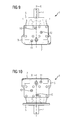
- the transmission unit 1 is used in an installed position, compared to the in the Figures 1 and 2 shown installation position is pivoted about the housing axis in a clockwise direction by 90 °, as shown in the FIGS. 7 and 8 1, the uppermost first bore 8 of the first group is for filling and bleeding the transmission case 2 and the second bore 9 of the first oil drain group, while the upper third third bore 12 of the second oil level gauge is used.
- the transmission unit 1 is shown in an installed position, which faces down the connection surface 7.
- the uppermost first bore 10 of the second group serves to fill and bleed the transmission housing 2 and the underlying third bore 12 of the second group of the measurement of the oil level.
- the downwardly directed two holes 8, 9 of the first group may optionally be used to drain oil from the transmission housing 2.
- the transmission unit 1 is shown in an installed position in which the connection surface 7 faces upward.
- the holes 8, 9 of the first group can optionally be used to fill the transmission housing 2 with oil or to vent.
- the second hole 11 of the third group which is then at the top, serves to measure the oil level, and the lower first hole 10 of the second group serves to drain oil.
- All holes 8 to 12 are closed during operation and can be designed for this purpose, for example, as threaded holes.
Landscapes
- Engineering & Computer Science (AREA)
- General Engineering & Computer Science (AREA)
- Mechanical Engineering (AREA)
- General Details Of Gearings (AREA)
Priority Applications (6)
| Application Number | Priority Date | Filing Date | Title |
|---|---|---|---|
| EP12154054.6A EP2623821A1 (fr) | 2012-02-06 | 2012-02-06 | Carter d'engrenages, unité d'engrenages avec un tel carter et moteur d'engrenages avec une telle unité |
| PCT/EP2013/050809 WO2013117397A1 (fr) | 2012-02-06 | 2013-01-17 | Carter de transmission, unité de transmission pourvue d'un tel carter de transmission et motoréducteur pourvu d'une telle unité de transmission |
| US14/376,705 US10495207B2 (en) | 2012-02-06 | 2013-01-17 | Gearbox housing, gearbox unit with such a gearbox housing and gear motor with such a gearbox unit |
| CN201380008042.3A CN104105906B (zh) | 2012-02-06 | 2013-01-17 | 变速器壳、具有这种变速器壳的变速单元及具有这种变速单元的变速发动机 |
| BR112014019304A BR112014019304A8 (pt) | 2012-02-06 | 2013-01-17 | Alojamento de caixa de câmbio, unidade de caixa de câmbio com tal alojamento de caixa de câmbio e motor de engrenagens com tal unidade de caixa de câmbio |
| EP13702363.6A EP2798242B1 (fr) | 2012-02-06 | 2013-01-17 | Carter d'engrenages, unité d'engrenages avec un tel carter et moteur d'engrenages avec une telle unité |
Applications Claiming Priority (1)
| Application Number | Priority Date | Filing Date | Title |
|---|---|---|---|
| EP12154054.6A EP2623821A1 (fr) | 2012-02-06 | 2012-02-06 | Carter d'engrenages, unité d'engrenages avec un tel carter et moteur d'engrenages avec une telle unité |
Publications (1)
| Publication Number | Publication Date |
|---|---|
| EP2623821A1 true EP2623821A1 (fr) | 2013-08-07 |
Family
ID=47632991
Family Applications (2)
| Application Number | Title | Priority Date | Filing Date |
|---|---|---|---|
| EP12154054.6A Withdrawn EP2623821A1 (fr) | 2012-02-06 | 2012-02-06 | Carter d'engrenages, unité d'engrenages avec un tel carter et moteur d'engrenages avec une telle unité |
| EP13702363.6A Revoked EP2798242B1 (fr) | 2012-02-06 | 2013-01-17 | Carter d'engrenages, unité d'engrenages avec un tel carter et moteur d'engrenages avec une telle unité |
Family Applications After (1)
| Application Number | Title | Priority Date | Filing Date |
|---|---|---|---|
| EP13702363.6A Revoked EP2798242B1 (fr) | 2012-02-06 | 2013-01-17 | Carter d'engrenages, unité d'engrenages avec un tel carter et moteur d'engrenages avec une telle unité |
Country Status (5)
| Country | Link |
|---|---|
| US (1) | US10495207B2 (fr) |
| EP (2) | EP2623821A1 (fr) |
| CN (1) | CN104105906B (fr) |
| BR (1) | BR112014019304A8 (fr) |
| WO (1) | WO2013117397A1 (fr) |
Cited By (2)
| Publication number | Priority date | Publication date | Assignee | Title |
|---|---|---|---|---|
| CN106224521A (zh) * | 2016-08-24 | 2016-12-14 | 常州市鑫尔减速机有限公司 | 便于加注润滑油的减速机 |
| CN106224523A (zh) * | 2016-08-24 | 2016-12-14 | 常州市鑫尔减速机有限公司 | 快速加注润滑油的减速机 |
Families Citing this family (5)
| Publication number | Priority date | Publication date | Assignee | Title |
|---|---|---|---|---|
| EP3023673B1 (fr) * | 2014-11-24 | 2018-01-31 | Siemens Aktiengesellschaft | Chaîne cinématique et dispositif adaptateur |
| JP6169636B2 (ja) * | 2015-03-13 | 2017-07-26 | ファナック株式会社 | 機器の可動部材に潤滑剤を供給する装置、および方法 |
| CN105697603A (zh) * | 2016-03-01 | 2016-06-22 | 宁波华盛联合制动科技有限公司 | 具有油量定位功能的液力缓速器 |
| JP7281686B2 (ja) * | 2019-03-22 | 2023-05-26 | ニデック株式会社 | 駆動装置、およびオイル交換方法 |
| JP7660495B2 (ja) * | 2021-12-24 | 2025-04-11 | 株式会社クボタ | 作業車 |
Citations (5)
| Publication number | Priority date | Publication date | Assignee | Title |
|---|---|---|---|---|
| US2536385A (en) * | 1945-08-09 | 1951-01-02 | Jeffrey Mfg Co | Speed reducer lubricating means |
| US3521504A (en) * | 1967-06-15 | 1970-07-21 | Helmut Jorg | Gear housing |
| JPS5213272U (fr) * | 1975-07-15 | 1977-01-29 | ||
| DE3321854A1 (de) * | 1983-06-16 | 1984-12-20 | Pfaff-Silberblau Hebezeugfabrik Gmbh, 8904 Friedberg | Spindelhub- bzw. -schubgetriebe |
| US5911793A (en) * | 1997-05-22 | 1999-06-15 | Kaye; Kenneth B. | Transmission with semi-floating shafts |
Family Cites Families (15)
| Publication number | Priority date | Publication date | Assignee | Title |
|---|---|---|---|---|
| US2750806A (en) * | 1956-06-19 | hobbs | ||
| US3486207A (en) * | 1965-02-12 | 1969-12-30 | Falk Corp | Method of manufacturing a speed reducer |
| AT271123B (de) * | 1967-06-15 | 1969-05-27 | Helmut Joerg | Getriebegehäuse |
| US4536335A (en) | 1982-06-18 | 1985-08-20 | Bristol-Myers Company | Carbapenem antibiotics |
| DE19715016A1 (de) | 1997-04-11 | 1998-10-15 | Flender Himmelwerk Gmbh | Zweiteiliges Gehäuse und Verfahren zu seiner Fertigung |
| BRPI0600700B1 (pt) * | 2006-03-03 | 2018-06-12 | Petroleo Brasileiro S.A. - Petrobras | Sistema tropicalizado de caixas de engrenagens para válvulas de bloqueio do setor petrolífero e método de descontaminação de caixas de engrenagens |
| ES2342688T3 (es) | 2006-05-24 | 2010-07-12 | Flender Tubingen Gmbh | Disposicion de accionamiento con dos ejes. |
| EP2063200A1 (fr) | 2007-11-22 | 2009-05-27 | Siemens Geared Motors GmbH | Agencement d'entraînement à deux axes |
| DE102009005346A1 (de) * | 2009-01-16 | 2010-07-22 | Sew-Eurodrive Gmbh & Co. Kg | Schneckengetriebe |
| DE102009005349A1 (de) | 2009-01-16 | 2010-07-22 | Sew-Eurodrive Gmbh & Co. Kg | Stirnradgetriebe |
| DE102009052352A1 (de) | 2009-11-07 | 2011-05-12 | Siemens Geared Motors Gmbh | Wellenlageranordnung |
| CN201599394U (zh) * | 2009-11-26 | 2010-10-06 | 杭州杰牌传动科技有限公司 | 多置式减速器箱体 |
| CN102312996A (zh) * | 2011-08-24 | 2012-01-11 | 无锡明珠增压器制造有限公司 | 一种改进的变速器油标装置 |
| CN102305284A (zh) * | 2011-08-24 | 2012-01-04 | 无锡明珠增压器制造有限公司 | 一种改进的变速器的放油装置 |
| EP2574824B1 (fr) | 2011-09-29 | 2014-06-25 | Siemens Aktiengesellschaft | Engrenage industriel |
-
2012
- 2012-02-06 EP EP12154054.6A patent/EP2623821A1/fr not_active Withdrawn
-
2013
- 2013-01-17 US US14/376,705 patent/US10495207B2/en not_active Expired - Fee Related
- 2013-01-17 EP EP13702363.6A patent/EP2798242B1/fr not_active Revoked
- 2013-01-17 CN CN201380008042.3A patent/CN104105906B/zh not_active Expired - Fee Related
- 2013-01-17 BR BR112014019304A patent/BR112014019304A8/pt not_active Application Discontinuation
- 2013-01-17 WO PCT/EP2013/050809 patent/WO2013117397A1/fr not_active Ceased
Patent Citations (5)
| Publication number | Priority date | Publication date | Assignee | Title |
|---|---|---|---|---|
| US2536385A (en) * | 1945-08-09 | 1951-01-02 | Jeffrey Mfg Co | Speed reducer lubricating means |
| US3521504A (en) * | 1967-06-15 | 1970-07-21 | Helmut Jorg | Gear housing |
| JPS5213272U (fr) * | 1975-07-15 | 1977-01-29 | ||
| DE3321854A1 (de) * | 1983-06-16 | 1984-12-20 | Pfaff-Silberblau Hebezeugfabrik Gmbh, 8904 Friedberg | Spindelhub- bzw. -schubgetriebe |
| US5911793A (en) * | 1997-05-22 | 1999-06-15 | Kaye; Kenneth B. | Transmission with semi-floating shafts |
Cited By (2)
| Publication number | Priority date | Publication date | Assignee | Title |
|---|---|---|---|---|
| CN106224521A (zh) * | 2016-08-24 | 2016-12-14 | 常州市鑫尔减速机有限公司 | 便于加注润滑油的减速机 |
| CN106224523A (zh) * | 2016-08-24 | 2016-12-14 | 常州市鑫尔减速机有限公司 | 快速加注润滑油的减速机 |
Also Published As
| Publication number | Publication date |
|---|---|
| EP2798242A1 (fr) | 2014-11-05 |
| BR112014019304A8 (pt) | 2017-07-11 |
| BR112014019304A2 (fr) | 2017-06-20 |
| CN104105906B (zh) | 2017-06-09 |
| CN104105906A (zh) | 2014-10-15 |
| WO2013117397A1 (fr) | 2013-08-15 |
| EP2798242B1 (fr) | 2016-06-15 |
| US10495207B2 (en) | 2019-12-03 |
| US20150007691A1 (en) | 2015-01-08 |
Similar Documents
| Publication | Publication Date | Title |
|---|---|---|
| EP2798242B1 (fr) | Carter d'engrenages, unité d'engrenages avec un tel carter et moteur d'engrenages avec une telle unité | |
| EP2147234B1 (fr) | Chapeau de palier, transmission, procédé et gamme de fabrication | |
| EP3384191B1 (fr) | Dispositif formant vanne | |
| DE102010050973A1 (de) | Rheometer oder Viskosimeter | |
| DE102015216693A1 (de) | Elektrische Verbinderanordnung, diese verwendende elektronische Steuereinheit und elektrisches Lenkkraftunterstützungssystem damit | |
| DE2901120A1 (de) | Getriebeeinheit fuer ein kraftfahrzeug | |
| DE1750886A1 (de) | Getriebegehaeuse | |
| DE1954682A1 (de) | Hydrostatische Maschine | |
| EP2933533A1 (fr) | Étage d'entrée d'une roue conique d'un engrenage planétaire | |
| DE102008022603B4 (de) | Schmiervorrichtung für einen Spindeltrieb einer Spritzgießmaschine | |
| DE112022006734T5 (de) | Elektronisches Expansionsventil | |
| DE3544238C2 (fr) | ||
| DE112018005739T5 (de) | Schneckengetriebeeinheit, Getriebe, Getriebemotor und elektrische Vorrichtung, die einen Getriebemotor aufweist | |
| DE2946293A1 (de) | Schmiermittelabzugssystem fuer ein getriebegehaeuse | |
| DE10054938C2 (de) | Modul einer elektromechanisch betätigbaren Scheibenbremse und Scheibenbremse mit einem solchen Modul | |
| DE112016000903T5 (de) | Motorvorrichtung | |
| DE2249952B2 (de) | Hydraulische Zahnradmaschine | |
| DE102014225446A1 (de) | Getriebeprüfstand für Luftfahrzeuggetriebe | |
| DE2709998C2 (de) | Flüssigkeitsdichte Gleitlagerung von Wellen in Kleinbauteilen | |
| DE3212667C2 (fr) | ||
| AT211511B (de) | Einrichtung zur elektrischen Schachtfördermaschinen zum Retardieren auf einen beliebigen Schachtpunkt | |
| DE520101C (de) | Feineinstellung fuer Aufzuege | |
| DE4394249B4 (de) | Verfahren für die Entrindung von Nutzholz | |
| DE202017006020U1 (de) | Elektrowerkzeug und Antriebswelle hierfür | |
| DE102006054402A1 (de) | Getriebe- und Kupplungssteuerung |
Legal Events
| Date | Code | Title | Description |
|---|---|---|---|
| PUAI | Public reference made under article 153(3) epc to a published international application that has entered the european phase |
Free format text: ORIGINAL CODE: 0009012 |
|
| AK | Designated contracting states |
Kind code of ref document: A1 Designated state(s): AL AT BE BG CH CY CZ DE DK EE ES FI FR GB GR HR HU IE IS IT LI LT LU LV MC MK MT NL NO PL PT RO RS SE SI SK SM TR |
|
| AX | Request for extension of the european patent |
Extension state: BA ME |
|
| STAA | Information on the status of an ep patent application or granted ep patent |
Free format text: STATUS: THE APPLICATION IS DEEMED TO BE WITHDRAWN |
|
| 18D | Application deemed to be withdrawn |
Effective date: 20140208 |