EP2623896A1 - Dispositif de stockage de chaleur et climatiseur comportant le dispositif de stockage de chaleur - Google Patents
Dispositif de stockage de chaleur et climatiseur comportant le dispositif de stockage de chaleur Download PDFInfo
- Publication number
- EP2623896A1 EP2623896A1 EP11828257.3A EP11828257A EP2623896A1 EP 2623896 A1 EP2623896 A1 EP 2623896A1 EP 11828257 A EP11828257 A EP 11828257A EP 2623896 A1 EP2623896 A1 EP 2623896A1
- Authority
- EP
- European Patent Office
- Prior art keywords
- heat storage
- heat
- heat exchanger
- compressor
- storage material
- Prior art date
- Legal status (The legal status is an assumption and is not a legal conclusion. Google has not performed a legal analysis and makes no representation as to the accuracy of the status listed.)
- Granted
Links
Images




Classifications
-
- F—MECHANICAL ENGINEERING; LIGHTING; HEATING; WEAPONS; BLASTING
- F28—HEAT EXCHANGE IN GENERAL
- F28D—HEAT-EXCHANGE APPARATUS, NOT PROVIDED FOR IN ANOTHER SUBCLASS, IN WHICH THE HEAT-EXCHANGE MEDIA DO NOT COME INTO DIRECT CONTACT
- F28D1/00—Heat-exchange apparatus having stationary conduit assemblies for one heat-exchange medium only, the media being in contact with different sides of the conduit wall, in which the other heat-exchange medium is a large body of fluid, e.g. domestic or motor car radiators
- F28D1/02—Heat-exchange apparatus having stationary conduit assemblies for one heat-exchange medium only, the media being in contact with different sides of the conduit wall, in which the other heat-exchange medium is a large body of fluid, e.g. domestic or motor car radiators with heat-exchange conduits immersed in the body of fluid
- F28D1/0206—Heat exchangers immersed in a large body of liquid
- F28D1/0213—Heat exchangers immersed in a large body of liquid for heating or cooling a liquid in a tank
-
- F—MECHANICAL ENGINEERING; LIGHTING; HEATING; WEAPONS; BLASTING
- F25—REFRIGERATION OR COOLING; COMBINED HEATING AND REFRIGERATION SYSTEMS; HEAT PUMP SYSTEMS; MANUFACTURE OR STORAGE OF ICE; LIQUEFACTION SOLIDIFICATION OF GASES
- F25B—REFRIGERATION MACHINES, PLANTS OR SYSTEMS; COMBINED HEATING AND REFRIGERATION SYSTEMS; HEAT PUMP SYSTEMS
- F25B47/00—Arrangements for preventing or removing deposits or corrosion, not provided for in another subclass
- F25B47/02—Defrosting cycles
-
- F—MECHANICAL ENGINEERING; LIGHTING; HEATING; WEAPONS; BLASTING
- F25—REFRIGERATION OR COOLING; COMBINED HEATING AND REFRIGERATION SYSTEMS; HEAT PUMP SYSTEMS; MANUFACTURE OR STORAGE OF ICE; LIQUEFACTION SOLIDIFICATION OF GASES
- F25B—REFRIGERATION MACHINES, PLANTS OR SYSTEMS; COMBINED HEATING AND REFRIGERATION SYSTEMS; HEAT PUMP SYSTEMS
- F25B31/00—Compressor arrangements
- F25B31/006—Cooling of compressor or motor
-
- F—MECHANICAL ENGINEERING; LIGHTING; HEATING; WEAPONS; BLASTING
- F28—HEAT EXCHANGE IN GENERAL
- F28D—HEAT-EXCHANGE APPARATUS, NOT PROVIDED FOR IN ANOTHER SUBCLASS, IN WHICH THE HEAT-EXCHANGE MEDIA DO NOT COME INTO DIRECT CONTACT
- F28D1/00—Heat-exchange apparatus having stationary conduit assemblies for one heat-exchange medium only, the media being in contact with different sides of the conduit wall, in which the other heat-exchange medium is a large body of fluid, e.g. domestic or motor car radiators
- F28D1/02—Heat-exchange apparatus having stationary conduit assemblies for one heat-exchange medium only, the media being in contact with different sides of the conduit wall, in which the other heat-exchange medium is a large body of fluid, e.g. domestic or motor car radiators with heat-exchange conduits immersed in the body of fluid
- F28D1/04—Heat-exchange apparatus having stationary conduit assemblies for one heat-exchange medium only, the media being in contact with different sides of the conduit wall, in which the other heat-exchange medium is a large body of fluid, e.g. domestic or motor car radiators with heat-exchange conduits immersed in the body of fluid with tubular conduits
- F28D1/047—Heat-exchange apparatus having stationary conduit assemblies for one heat-exchange medium only, the media being in contact with different sides of the conduit wall, in which the other heat-exchange medium is a large body of fluid, e.g. domestic or motor car radiators with heat-exchange conduits immersed in the body of fluid with tubular conduits the conduits being bent, e.g. in a serpentine or zig-zag
- F28D1/0477—Heat-exchange apparatus having stationary conduit assemblies for one heat-exchange medium only, the media being in contact with different sides of the conduit wall, in which the other heat-exchange medium is a large body of fluid, e.g. domestic or motor car radiators with heat-exchange conduits immersed in the body of fluid with tubular conduits the conduits being bent, e.g. in a serpentine or zig-zag the conduits being bent in a serpentine or zig-zag
-
- F—MECHANICAL ENGINEERING; LIGHTING; HEATING; WEAPONS; BLASTING
- F28—HEAT EXCHANGE IN GENERAL
- F28D—HEAT-EXCHANGE APPARATUS, NOT PROVIDED FOR IN ANOTHER SUBCLASS, IN WHICH THE HEAT-EXCHANGE MEDIA DO NOT COME INTO DIRECT CONTACT
- F28D20/00—Heat storage plants or apparatus in general; Regenerative heat-exchange apparatus not covered by groups F28D17/00 or F28D19/00
-
- F—MECHANICAL ENGINEERING; LIGHTING; HEATING; WEAPONS; BLASTING
- F28—HEAT EXCHANGE IN GENERAL
- F28D—HEAT-EXCHANGE APPARATUS, NOT PROVIDED FOR IN ANOTHER SUBCLASS, IN WHICH THE HEAT-EXCHANGE MEDIA DO NOT COME INTO DIRECT CONTACT
- F28D20/00—Heat storage plants or apparatus in general; Regenerative heat-exchange apparatus not covered by groups F28D17/00 or F28D19/00
- F28D20/0034—Heat storage plants or apparatus in general; Regenerative heat-exchange apparatus not covered by groups F28D17/00 or F28D19/00 using liquid heat storage material
-
- F—MECHANICAL ENGINEERING; LIGHTING; HEATING; WEAPONS; BLASTING
- F28—HEAT EXCHANGE IN GENERAL
- F28F—DETAILS OF HEAT-EXCHANGE AND HEAT-TRANSFER APPARATUS, OF GENERAL APPLICATION
- F28F19/00—Preventing the formation of deposits or corrosion, e.g. by using filters or scrapers
-
- F—MECHANICAL ENGINEERING; LIGHTING; HEATING; WEAPONS; BLASTING
- F25—REFRIGERATION OR COOLING; COMBINED HEATING AND REFRIGERATION SYSTEMS; HEAT PUMP SYSTEMS; MANUFACTURE OR STORAGE OF ICE; LIQUEFACTION SOLIDIFICATION OF GASES
- F25B—REFRIGERATION MACHINES, PLANTS OR SYSTEMS; COMBINED HEATING AND REFRIGERATION SYSTEMS; HEAT PUMP SYSTEMS
- F25B2400/00—Component parts or details not otherwise provided for in this subclass
- F25B2400/05—Compression system with heat exchange between particular parts of the system
- F25B2400/053—Compression system with heat exchange between particular parts of the system between the storage receiver and another part of the system
-
- F—MECHANICAL ENGINEERING; LIGHTING; HEATING; WEAPONS; BLASTING
- F25—REFRIGERATION OR COOLING; COMBINED HEATING AND REFRIGERATION SYSTEMS; HEAT PUMP SYSTEMS; MANUFACTURE OR STORAGE OF ICE; LIQUEFACTION SOLIDIFICATION OF GASES
- F25B—REFRIGERATION MACHINES, PLANTS OR SYSTEMS; COMBINED HEATING AND REFRIGERATION SYSTEMS; HEAT PUMP SYSTEMS
- F25B2400/00—Component parts or details not otherwise provided for in this subclass
- F25B2400/24—Thermal storage element
-
- F—MECHANICAL ENGINEERING; LIGHTING; HEATING; WEAPONS; BLASTING
- F25—REFRIGERATION OR COOLING; COMBINED HEATING AND REFRIGERATION SYSTEMS; HEAT PUMP SYSTEMS; MANUFACTURE OR STORAGE OF ICE; LIQUEFACTION SOLIDIFICATION OF GASES
- F25B—REFRIGERATION MACHINES, PLANTS OR SYSTEMS; COMBINED HEATING AND REFRIGERATION SYSTEMS; HEAT PUMP SYSTEMS
- F25B47/00—Arrangements for preventing or removing deposits or corrosion, not provided for in another subclass
- F25B47/02—Defrosting cycles
- F25B47/022—Defrosting cycles hot gas defrosting
-
- F—MECHANICAL ENGINEERING; LIGHTING; HEATING; WEAPONS; BLASTING
- F28—HEAT EXCHANGE IN GENERAL
- F28D—HEAT-EXCHANGE APPARATUS, NOT PROVIDED FOR IN ANOTHER SUBCLASS, IN WHICH THE HEAT-EXCHANGE MEDIA DO NOT COME INTO DIRECT CONTACT
- F28D1/00—Heat-exchange apparatus having stationary conduit assemblies for one heat-exchange medium only, the media being in contact with different sides of the conduit wall, in which the other heat-exchange medium is a large body of fluid, e.g. domestic or motor car radiators
- F28D1/02—Heat-exchange apparatus having stationary conduit assemblies for one heat-exchange medium only, the media being in contact with different sides of the conduit wall, in which the other heat-exchange medium is a large body of fluid, e.g. domestic or motor car radiators with heat-exchange conduits immersed in the body of fluid
- F28D2001/0253—Particular components
- F28D2001/026—Cores
- F28D2001/0273—Cores having special shape, e.g. curved, annular
-
- F—MECHANICAL ENGINEERING; LIGHTING; HEATING; WEAPONS; BLASTING
- F28—HEAT EXCHANGE IN GENERAL
- F28F—DETAILS OF HEAT-EXCHANGE AND HEAT-TRANSFER APPARATUS, OF GENERAL APPLICATION
- F28F2275/00—Fastening; Joining
- F28F2275/04—Fastening; Joining by brazing
-
- Y—GENERAL TAGGING OF NEW TECHNOLOGICAL DEVELOPMENTS; GENERAL TAGGING OF CROSS-SECTIONAL TECHNOLOGIES SPANNING OVER SEVERAL SECTIONS OF THE IPC; TECHNICAL SUBJECTS COVERED BY FORMER USPC CROSS-REFERENCE ART COLLECTIONS [XRACs] AND DIGESTS
- Y02—TECHNOLOGIES OR APPLICATIONS FOR MITIGATION OR ADAPTATION AGAINST CLIMATE CHANGE
- Y02E—REDUCTION OF GREENHOUSE GAS [GHG] EMISSIONS, RELATED TO ENERGY GENERATION, TRANSMISSION OR DISTRIBUTION
- Y02E60/00—Enabling technologies; Technologies with a potential or indirect contribution to GHG emissions mitigation
- Y02E60/14—Thermal energy storage
Definitions
- the present invention relates to a heat storage device accommodating a heat storage material that stores heat generated by a compressor, as well as to an air conditioner having the heat storage device.
- a conventional heat pump air conditioner performs defrosting by switching from a heating cycle to a cooling cycle with use of a four-way valve when frost has been formed on an outdoor heat exchanger during heating operation.
- this defrosting method although an indoor fan is stopped, cold air gradually flows out of an indoor unit, thus posing a defect of warmth being lost.
- Figs. 10 and 11 are sectional views exemplifying a conventional heat storage device.
- a heat storage device 100 includes a hermetic heat storage box 106 having a generally hollow cylindrical shape, disposed around a compressor 102, which serves as a heat generator, and filled with a heat storage material 104, a heat exchanger 108 for heat storage and heat radiation accommodated in the hermetic heat storage box 106, and the like.
- the hermetic heat storage box 106 is formed into the generally hollow cylindrical shape by sealing an upper end of a casing 110 made of, for example, an aluminum thin plate, and the heat storage material 104 is filled in the casing 110.
- the heat exchanger 108 is formed by securing a fin 114 made of aluminum or the like to a pipe 112 as a passage of a refrigerant, for example.
- heat generated by the compressor 102 is transferred to the hermetic heat storage box 106 via silicon oil 116 and stored in the heat storage material 104 in the hermetic heat storage box 106.
- Patent Document 1 JP 02-128065 U
- the refrigerant passage pipe 112 is disposed in the heat storage device 100 over a wide range from a position adjacent to an upper end to a position adjacent to a lower end of the heat storage device 100.
- piping configuring a refrigeration cycle such as the refrigerant passage pipe, is formed by connecting a plurality of pipes by means of brazing, welding, a flare groove joint, or the like.
- the conventional technique mentioned above does not include any particular consideration of the position of such a joint portion.
- the heat exchanger 108 of a fin tube type as in the conventional technique mentioned above is generally produced by inserting a copper pipe of a hair pin shape through a hole in an aluminum fin material, attaching a return bend to each end, and integrally brazing a joint portion between the hair pin copper pipe and the return bend.
- the joint portion immersed in the heat storage material is more likely to corrode rather than the other portions, leading to problematic reliability of the refrigeration cycle.
- the present invention has been made in view of such a problem of the conventional technique. It is an object of the present invention to provide a heat storage device that can efficiently store heat in a heat storage material or efficiently obtain stored heat, with reliability secured for a long period of time.
- the present invention provides a heat storage device, disposed to surround a compressor, for storing heat generated by the compressor.
- the heat storage device includes a heat storage tank accommodating a heat storage material storing heat generated by the compressor, and a heat storage heat exchanger accommodated in the heat storage tank. Pipes configuring a refrigeration cycle have a joint portion that is disposed so as not to be immersed in the heat storage material.
- the joint portion between the pipes which is more likely to corrode in comparison to the pipes and largely influences maintenance of the function, is not immersed in the heat storage material. Even if the pipes configuring the refrigeration cycle are immersed in the heat storage material and the heat storage material or a material for the pipes along with the heat storage material affects the pipes, it is possible to keep reliability for a long period of time.
- the present invention provides a heat storage device, disposed to surround a compressor, for storing heat generated by the compressor.
- the heat storage device includes a heat storage tank accommodating a heat storage material storing heat generated by the compressor, and a heat storage heat exchanger accommodated in the heat storage tank. Pipes configuring a refrigeration cycle have a joint portion that is disposed so as not to be immersed in the heat storage material.
- the joint portion between the pipes which is more likely to corrode in comparison to the pipes and largely influences maintenance of the function, is not immersed in the heat storage material. Even if a substance contained in the heat storage material affects the joint portion, it is possible to keep reliability for a long period of time.
- the heat storage material preferably includes glycol.
- Glycol has relatively high specific heat and is less corrosive, and aqueous solution thereof increases the boiling point and decreases the freezing point, which is excellent as the heat storage material.
- the joint portion is positioned outside the container filled with the heat storage material.
- the joint portion When the joint portion is located outside the container filled with the heat storage material, the joint portion will not be brought into contact with the heat storage material even if the heat storage material moves due to vibration or an outdoor unit is installed obliquely. The joint portion will not corrode accordingly.
- Fig. 1 depicts a configuration of an air conditioner including a heat storage device according to the present invention.
- the air conditioner includes an outdoor unit 2 and an indoor unit 4 connected to each other via refrigerant piping.
- the outdoor unit 2 accommodates therein a compressor 6, a four-way valve 8, a strainer 10, an expansion valve 12, and an outdoor heat exchanger 14, while the indoor unit 4 accommodates an indoor heat exchanger 16 therein.
- These components are connected to each other via refrigerant piping so as to configure a refrigeration cycle.
- the compressor 6 and the indoor heat exchanger 16 are connected to each other via a first pipe 18 on which the four-way valve 8 is provided, and the indoor heat exchanger 16 and the expansion valve 12 are connected to each other via a second pipe 20 on which the strainer 10 is provided. Furthermore, the expansion valve 12 and the outdoor heat exchanger 14 are connected to each other via a third pipe 22, and the outdoor heat exchanger 14 and the compressor 6 are connected to each other via a fourth pipe 24.
- the four-way valve 8 is located midway on the fourth pipe 24, and an accumulator 26 for separating a liquid refrigerant and a gaseous refrigerant is provided on the fourth pipe 24 on a refrigerant suction side of the compressor 6.
- the compressor 6 and the third pipe 22 are connected to each other via a fifth pipe 28, on which a first solenoid valve 30 is provided.
- a heat storage tank 32 accommodating a heat storage heat exchanger 34 therein is provided around the compressor 6 and filled with a heat storage material (for example, ethylene glycol aqueous solution) 36 used for exchanging heat with the heat storage heat exchanger 34.
- a heat storage material for example, ethylene glycol aqueous solution
- the heat storage tank 32, the heat storage heat exchanger 34, and the heat storage material 36 constitute the heat storage device.
- the second pipe 20 and the heat storage heat exchanger 34 are connected to each other via a sixth pipe 38, and the heat storage heat exchanger 34 and the fourth pipe 24 are connected to each other via a seventh pipe 40.
- a second solenoid valve 42 is provided on the sixth pipe 38.
- the indoor unit 4 accommodates therein, in addition to the indoor heat exchanger 16, a ventilation fan (not shown), vertical wind direction changing blades (not shown), and horizontal wind direction changing blades (not shown).
- the indoor heat exchanger 16 exchanges heat between indoor air sucked into the indoor unit 4 by the ventilation fan and a refrigerant flowing through the indoor heat exchanger 16 so that air heated or cooled by heat exchange may be blown into a room during heating or cooling, respectively.
- the vertical wind direction changing blades vertically change the direction of air blown out of the indoor unit 4 and the horizontal wind direction changing blades horizontally change the direction of air brown out of the indoor unit 4.
- the compressor 6, the ventilation fan, the vertical wind direction changing blades, the horizontal wind direction changing blades, the four-way valve 8, the expansion valve 12, the solenoid valves 30 and 42, and the like are electrically connected to and controlled by a controller (for example, a microcomputer not shown).
- a controller for example, a microcomputer not shown.
- connection relationship between and functions of the components in refrigeration cycle equipment thus configured according to the present invention are described below with reference to a flow of the refrigerant, exemplifying the case of heating operation.
- the refrigerant discharged from a discharge port of the compressor 6 passes through the four-way valve 8 and reaches the indoor heat exchanger 16 via the first pipe 18.
- the refrigerant condenses in the indoor heat exchanger 16 by exchanging heat with indoor air, leaves the indoor heat exchanger 16, and passes through the second pipe 20 as well as through the strainer 10, which prevents invasion of foreign substances into the expansion valve 12, before the refrigerant reaches the expansion valve 12.
- the refrigerant is reduced in pressure by the expansion valve 12 and reaches the outdoor heat exchanger 14 via the third pipe 22.
- the refrigerant then evaporates in the outdoor heat exchanger 14 by exchanging heat with outdoor air and passes through the fourth pipe 24, the four-way valve 8, and the accumulator 26, before the refrigerant returns to a suction port of the compressor 6.
- the heat storage tank 32 accommodating therein the heat storage material 36 and the heat storage heat exchanger 34 is disposed to surround and contact the compressor 6, so as to store heat generated by the compressor 6 in the heat storage material 36.
- the sixth pipe 38 branched from the second pipe 20 between the indoor heat exchanger 16 and the strainer 10 reaches an inlet of the heat storage heat exchanger 34 via the second solenoid valve 42, and the seventh pipe 40 extending from an outlet of the heat storage heat exchanger 34 joins the fourth pipe 24 between the four-way valve 8 and the accumulator 26.
- FIG. 2 schematically depicts the operation of the air conditioner of Fig. 1 and a flow of the refrigerant during normal heating.
- the first solenoid valve 30 and the second solenoid valve 42 are controlled to be closed.
- the refrigerant discharged from the discharge port of the compressor 6 passes through the four-way valve 8 and reaches the indoor heat exchanger 16 via the first pipe 18.
- the refrigerant leaves the indoor heat exchanger 16 passes through the second pipe 20, and reaches the expansion valve 12.
- the refrigerant is then reduced in pressure by the expansion valve 12 and reaches the outdoor heat exchanger 14 via the third pipe 22.
- the refrigerant passes through the fourth pipe 24 as well as through the four-way valve 8 and returns to the suction port of the compressor 6.
- Heat generated by the compressor 6 is transferred from an outer wall of the compressor 6 to an outer wall of the heat storage tank 32 and is stored in the heat storage material 36 that is accommodated in the heat storage tank 32.
- FIG. 3 schematically depicts the operation of the air conditioner of Fig. 1 and a flow of the refrigerant during defrosting/heating.
- solid arrows indicate a flow of the refrigerant used for heating
- dotted arrows indicate a flow of the refrigerant used for defrosting.
- the air conditioner according to the present invention is provided with a temperature sensor 44 for detecting piping temperature of the outdoor heat exchanger 14, and if this temperature sensor 44 detects reduction in evaporating temperature as compared with the case where no frost is formed, the controller outputs a command to shift from normal heating operation to defrosting/heating operation.
- the first solenoid valve 30 and the second solenoid valve 42 are controlled to be opened.
- part of a gaseous refrigerant discharged from the discharge port of the compressor 6 passes through the fifth pipe 28 and the first solenoid valve 30 and joins the refrigerant passing through the third pipe 22 to heat the outdoor heat exchanger 14.
- the refrigerant passes through the fourth pipe 24 and returns to the suction port of the compressor 6 via the four-way valve 8 and the accumulator 26.
- part of the liquid refrigerant diverged from the second pipe 20 between the indoor heat exchanger 16 and the strainer 10 passes through the sixth pipe 38 and the second solenoid valve 42 and absorbs heat from the heat storage material 36 in the heat storage heat exchanger 34.
- the liquid refrigerant then evaporates and turns into a gas phase.
- the resultant gaseous refrigerant passes through the seventh pipe 40, joins the refrigerant passing through the fourth pipe 24, and returns to the suction port of the compressor 6 via the accumulator 26.
- the joining position may be between the accumulator 26 and the compressor 6. In such a case, it is possible to avoid absorption of heat due to heat capacity of the accumulator 26 itself.
- the refrigerant returning to the accumulator 26 contains the liquid refrigerant returning from the outdoor heat exchanger 14, the latter is admixed with the hot gaseous refrigerant returning from the heat storage heat exchanger 34 to thereby promote evaporation of the liquid refrigerant. Accordingly, the liquid refrigerant may not pass through the accumulator 26 and return to the compressor 6, thus making it possible to enhance the reliability of the compressor 6.
- the temperature of the outdoor heat exchanger 14 is below the freezing point due to adhesion of frost, but when the outdoor heat exchanger 14 is heated by the gaseous refrigerant discharged from the discharge port of the compressor 6, frost melts at around zero degree and the temperature of the outdoor heat exchanger 14 starts to increase again upon termination of melting of the frost.
- the temperature sensor 44 detects such temperature rise of the outdoor heat exchanger 14, it is determined that defrosting has been completed and the controller outputs a command to shift from defrosting/heating operation to normal heating operation.
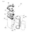
- Figs. 4 and 5 each depict the heat storage device.
- the heat storage device includes the heat storage tank 32, the heat storage heat exchanger 34, and the heat storage material 36.
- Fig. 4 depicts a state where the compressor 6 and the accumulator 26 attached to the compressor 6 are installed in the heat storage device.
- Fig. 5 is an exploded perspective view of the heat storage device.
- the heat storage tank 32 includes a heat storage tank body 46 made of resin and having an upper opening, as well as a side wall 46a and a bottom wall (not shown), a lid 48 made of resin and closing the upper opening of the heat storage tank body 46, and a packing member 50 made of, for example, silicon rubber and interposed between the heat storage tank body 46 and the lid 48.
- the lid 48 is screwed to the heat storage tank body 46.
- the side wall 46a of the heat storage tank body 46 is partially opened (specifically, the portion of the side wall 46a facing the compressor 6), and a contact member 52 is joined to a peripheral edge of this opening 46b so as to be brought into close contact with the outer peripheral surface of the compressor 6.
- the contact member 52 includes a frame 54 and a sheet member 56, and has a generally cylindrical shape of a predetermined diameter and is partially cut off.
- the compressor 6 is accommodated in the contact member 52, so that the inner diameter of the contact member 52 is set to be slightly larger than the outer diameter of the compressor 6 in consideration of mounting tolerance and the like.
- the frame 54 has an opening 54a from an intermediate portion to a lower portion thereof in the vertical direction.
- the sheet member 56 is joined to the frame 54 so as to close the opening 54a.
- the heat storage tank 32 is closely fixed to the compressor 6 by means of a band 33.
- Fig. 5 exemplifies the case where the opening 46b is provided in the side wall 46a.
- the present invention is not limited to this configuration.
- the opening 46b may not be provided.
- there may be interposed, between the heat storage tank 32 and the compressor 6, a resin (such as silicon) sheet member, which is elastic and excellent in heat transfer property.
- the heat storage heat exchanger 34 is configured by, for example, a copper pipe bent into a serpiginous shape and is accommodated in the heat storage tank body 46.
- the heat storage heat exchanger 34 has opposite ends extending upward from the lid 48. One of the ends is connected to the sixth pipe 38 (see Fig. 1 ), while the other one of the ends is connected to the seventh pipe 40 (see Fig. 1 ).
- the heat storage tank body 46 which is surrounded with the side wall 46a, the bottom wall, and the contact member 52, has an internal space accommodating the heat storage heat exchanger 34 and filled with the heat storage material 36.
- the heat storage device is provided with agitating means for agitating the heat storage material 36 filled therein. If not, temperature distribution of the heat storage material 36 is not uniform. Therefore, in the present invention, in view of efficient heat exchange, the heat storage heat exchanger 34 bent into the serpiginous shape is preferably disposed at an upper portion of the heat storage tank 32.
- the amount of heat exchanged between the refrigerant passing through the heat storage heat exchanger 34 and the heat storage material 36 for exchanging heat with the refrigerant increases along with increase in temperature difference, followed by reduction in time period for defrosting.
- the high-temperature heat storage material 36 gathers in an upper portion in the heat storage tank 32 and the low-temperature heat storage material 36 gathers in a lower portion in the heat storage tank 32. As shown in Figs.
- the heat storage heat exchanger 34 has a bent portion 34a and straight portions 34b extending linearly upward from opposite ends of the bent portion 34a, and the bent portion 34a is entirely disposed so as to snake along an inner wall surface of the heat storage tank body 46 within a predetermined range of the upper portion of the heat storage tank 32.
- H1 The height of the heat storage tank 32 from a bottom surface thereof is indicated by H1
- H2 H1/2
- H4 the distance from an upper surface of the heat storage tank 32 to an upper end of the bent portion 34a of the heat storage heat exchanger 34 is indicated by H4.
- H3 and H4 are set to a predetermined height and a predetermined distance, respectively.
- a vertical position CoB of the center of gravity of the heat storage heat exchanger 34 is set to be higher than the vertical position H2 of the center of the heat storage tank 32. It is to be noted that the vertical position CoB of the center of gravity of the heat storage heat exchanger 34 corresponds to a position of the center of gravity of a combination of the bent portion 34a and the straight portions 34b of the heat storage heat exchanger 34.
- heat generated by the compressor 6 is stored in the heat storage material 36, in which the temperature of the heat storage material 36 located at an upper portion of the heat storage tank 32 is higher than that of the heat storage material 36 located at a lower portion of the heat storage tank 32.
- the heat storage heat exchanger 34 because the center of gravity of the heat storage heat exchanger 34 is set to be higher than the vertical position of the center of the heat storage tank 32, the heat storage heat exchanger 34 exchanges heat mainly with the relatively high-temperature portion of the heat storage material 36. In other words, the heat storage heat exchanger 34 according to the present invention can efficiently exchange heat with the heat storage material 36.
- the height H3 of the lower end of the heat storage heat exchanger 34 is lower than the height H2 of the center of the heat storage tank 32 and is positioned in the vicinity of the height H2 of the center.
- the entire heat storage heat exchanger 34 is made in contact with the higher-temperature heat storage material 36.
- the heat storage heat exchanger 34 can thus exchange heat more efficiently with the heat storage material 36.
- the distance H4 from the upper surface of the heat storage tank 32 to the upper end of the bent portion 34a of the heat storage heat exchanger 34 is determined in consideration of inclination of the heat storage tank 32. More specifically, the compressor 6 and the heat storage tank 32 are generally accommodated in the outdoor unit 2, which is sometimes installed outside at an angle. In consideration of such inclination, the heat storage heat exchanger 34 is installed in the heat storage tank 32 such that the upper end of the bent portion 34a of the heat storage heat exchanger 34 is positioned below the upper surface of the heat storage tank 32 by the predetermined distance H4.
- the bent portion 34a of the heat storage heat exchanger 34 is always immersed in the heat storage material 36.
- the heat storage material 36 occupies about 80% of the maximum capacity of the heat storage tank 32 at ordinary temperature.
- an additive such as a pH adjuster or an antioxidant may be added to the heat storage material 36.
- the additive such as the pH adjuster or the antioxidant is limited in added amount to the heat storage material 36. The effect thereof deteriorates gradually with time, and generated organic acids gradually increase in amount. As a result, the organic acids thus generated gradually decrease pH of the heat storage material 36.
- the pH is decreased more significantly as the organic acids generated in the heat storage material 36 increase in amount, and the degree of corrosion with respect to metal increases along with such decrease in pH.
- pipes are connected with each other at a joint portion 34j generally by means of brazing, welding, or a flare groove joint. In any case, there is formed a slight gap 34g at the joint portion 34j.
- glycolic acid has strong affinity with copper, which is a metal material for a pipe member, and forms coordinate bond to copper, so that glycolic acid having invaded in the slight gap 34g is less likely to flow outside.
- glycolic acid tends to gradually increase in concentration as compared to the heat storage material 36 outside the slight gap 34g.
- the additive such as the pH adjuster or the antioxidant is less likely to additionally flow into the slight gap 34g.
- the additive will not be sufficiently effective in the slight gap 34g.
- the acid concentration increases locally in the slight gap 34g, so that pH of the heat storage material 36 decreases locally.
- the joint portion 34j is thus more likely to be corroded in comparison to the copper pipe portion having no joint portion (in other words, seamless) as in the present embodiment.
- metal of the pipes of the heat storage heat exchanger 34 is increased in grain size by being heated at high temperature during brazing or welding, so that the metallographic structure is uneven in and around the heated portion.
- the heat storage heat exchanger 34 is immersed in the heat storage material 36 that is an electrolyte including generated organic acids, and thus a local cell is more likely to be formed. Such a portion is more likely to corrode in comparison to the portions not heated during brazing or welding.
- the heat storage material 36 may corrode, due to the influence of generated organic acids, to some extent, a member (copper, for example) configuring the refrigeration cycle such as the pipe or the heat exchanger. If the joint portion 34j and the heat storage material 36 are configured to be in contact with each other, the joint portion is in particular more likely to corrode due to corrosion in the gap in comparison to a pipe body 34p, thereby defectively deteriorating in reliability.
- the heat storage heat exchanger tends to be broken by internal pressure of the refrigerant.
- the heat storage heat exchanger 34 includes the portion immersed in the heat storage material 36, which is not brazed but is formed by bending a seamless copper pipe.
- the brazed portion is located at a position never in contact with the heat storage material 36. More specifically, the brazed portion is preferably located outside the heat storage tank 32 that serves as a container filled with the heat storage material 36. If there is a portion in the heat storage tank 32 not immersed in the heat storage material 36 by adjustment of the amount of the heat storage material 36 filled in the heat storage tank 32, the joint portion such as the brazed portion may be located in such a portion in the heat storage tank 32.
- the liquid level of the heat storage material 36 may shift vertically or the heat storage material 36 may splash to be brought into contact with the brazed portion.
- the joint portion is desirably coated with epoxy resin or the like, or provided with a cover so as to prevent such contact between the joint portion and the heat storage material 36.
- the heat storage device is detachably mounted on the compressor 6, an outer shell of the compressor 6 and the heat storage tank body 46 may be each made of metal and these may be firmly fixed to each other by, for example, welding.
- heat generated by the compressor 6 is transferred from the outer wall of the compressor 6 to the outer wall of the heat storage tank 32 and is stored in the heat storage material 36 that is accommodated in the heat storage tank 32.
- the compressor 6 has an operation frequency that is controlled in accordance with the operation state of the air conditioner so as to achieve most appropriate air conditioning performance.
- the compressor 6, which is used as the heat source may possibly have a calorific value or a temperature value that are not kept most appropriately for storing heat.
- the compressor 6 Under a condition with a high air conditioning load requiring high heating performance, the compressor 6 keeps operating at a high frequency and is accordingly kept at high temperature.
- the heat storage material 36 may be possibly left in such a hot environment for a long period of time. If waste heat of the compressor 6 is collected in the heat storage material 36, the joint portion is particularly desirably made not to be immersed in the heat storage material 36.
- the center of gravity of the heat storage heat exchanger 34 is located above H2, the present invention is not limited to this case. Alternatively, a center in the entire length of the pipe of the heat storage heat exchanger 34 may be positioned above H2. Still alternatively, the center of gravity or the center of the heat storage heat exchanger 34 may be positioned at H2 or below H2.
- the heat storage tank 32 is extended to be higher than the compressor 6 and the heat storage heat exchanger 34 is provided also in the extended portion. In this case, it is possible to secure heat capacity.
- glycol is included in the heat storage material 36.
- metal in contact with electrolyte solution forms a local cell and is corroded by an electrochemical action.
- the present invention is useful in a case where the heat storage material 36 includes any electrolyte or any material generating an electrolyte with time.
- the present invention is also useful, in addition to against an electrolyte, in a case where the heat storage material 36 is corrosive to metal of any type.
- the joint portion of the heat storage heat exchanger is appropriately positioned in consideration of improvement in reliability.
- the present invention is thus useful in an air conditioner, a refrigerator, a water heater, a heat pump washing machine, or the like.
Landscapes
- Engineering & Computer Science (AREA)
- Physics & Mathematics (AREA)
- Mechanical Engineering (AREA)
- Thermal Sciences (AREA)
- General Engineering & Computer Science (AREA)
- Compression-Type Refrigeration Machines With Reversible Cycles (AREA)
- Other Air-Conditioning Systems (AREA)
Applications Claiming Priority (2)
| Application Number | Priority Date | Filing Date | Title |
|---|---|---|---|
| JP2010221138A JP2012077939A (ja) | 2010-09-30 | 2010-09-30 | 蓄熱装置及び該蓄熱装置を備えた空気調和機 |
| PCT/JP2011/001088 WO2012042687A1 (fr) | 2010-09-30 | 2011-02-25 | Dispositif de stockage de chaleur et climatiseur comportant le dispositif de stockage de chaleur |
Publications (3)
| Publication Number | Publication Date |
|---|---|
| EP2623896A1 true EP2623896A1 (fr) | 2013-08-07 |
| EP2623896A4 EP2623896A4 (fr) | 2016-03-09 |
| EP2623896B1 EP2623896B1 (fr) | 2021-04-14 |
Family
ID=45892190
Family Applications (1)
| Application Number | Title | Priority Date | Filing Date |
|---|---|---|---|
| EP11828257.3A Active EP2623896B1 (fr) | 2010-09-30 | 2011-02-25 | Climatiseur comportant un dispositif de stockage de chaleur |
Country Status (6)
| Country | Link |
|---|---|
| EP (1) | EP2623896B1 (fr) |
| JP (1) | JP2012077939A (fr) |
| KR (1) | KR20130099983A (fr) |
| CN (1) | CN103154643B (fr) |
| BR (1) | BR112013007273A2 (fr) |
| WO (1) | WO2012042687A1 (fr) |
Cited By (3)
| Publication number | Priority date | Publication date | Assignee | Title |
|---|---|---|---|---|
| ITUA20162463A1 (it) * | 2016-04-11 | 2017-10-11 | Begafrost S R L | Sistema di sbrinamento dell'evaporatore esterno per impianti a pompa di calore. |
| EP3244141A1 (fr) * | 2016-05-09 | 2017-11-15 | Vaillant GmbH | Dégivrage avec de la chaleur générée par moteur de compresseur |
| EP3169950A4 (fr) * | 2014-07-17 | 2018-07-11 | Electrolux (Hangzhou) Home Appliances CO., LTD. | Système de pompe à chaleur |
Family Cites Families (19)
| Publication number | Priority date | Publication date | Assignee | Title |
|---|---|---|---|---|
| FR1416502A (fr) * | 1964-09-16 | 1965-11-05 | Hotchkiss Brandt | Méthode pour activer l'évaporation de l'eau de dégivrage d'un réfrigérateur |
| JPH01118080A (ja) * | 1987-10-30 | 1989-05-10 | Matsushita Electric Ind Co Ltd | ヒートポンプ式空気調和機 |
| JPH0730940B2 (ja) * | 1988-06-10 | 1995-04-10 | ダイキン工業株式会社 | 空気調和機 |
| JP2503637B2 (ja) * | 1989-03-22 | 1996-06-05 | ダイキン工業株式会社 | 冷凍装置用圧縮機 |
| JP2717106B2 (ja) * | 1989-11-17 | 1998-02-18 | 京セラ株式会社 | 蓄熱装置 |
| JPH04340057A (ja) * | 1991-05-16 | 1992-11-26 | Sharp Corp | 空気調和機 |
| JPH0510605A (ja) * | 1991-07-04 | 1993-01-19 | Daikin Ind Ltd | 圧縮機用蓄熱装置 |
| JPH0576925A (ja) * | 1991-09-21 | 1993-03-30 | Furukawa Electric Co Ltd:The | 多穴管の製造方法 |
| JPH05302771A (ja) * | 1992-04-27 | 1993-11-16 | Daikin Ind Ltd | 空気調和機 |
| JP3010934B2 (ja) * | 1992-08-28 | 2000-02-21 | ダイキン工業株式会社 | 空気調和機 |
| JPH08247627A (ja) * | 1995-03-14 | 1996-09-27 | Matsushita Refrig Co Ltd | 蒸発装置 |
| JPH09144991A (ja) * | 1995-11-24 | 1997-06-03 | Furukawa Electric Co Ltd:The | アルミニウム樹脂複合管及びその製造方法 |
| JP3360637B2 (ja) * | 1998-03-02 | 2002-12-24 | 三菱電機株式会社 | 冷凍空調装置 |
| JP2000088297A (ja) * | 1998-09-17 | 2000-03-31 | Hitachi Ltd | 氷蓄熱式空気調和装置及び氷蓄熱槽 |
| JP3837613B2 (ja) * | 2000-05-22 | 2006-10-25 | 株式会社日立製作所 | 製氷用熱交換器 |
| DE10323851A1 (de) * | 2003-05-26 | 2004-12-16 | BSH Bosch und Siemens Hausgeräte GmbH | Kältegerät mit Tauwsserverdampfer |
| JP4367237B2 (ja) * | 2004-05-31 | 2009-11-18 | ダイキン工業株式会社 | 空気調和装置 |
| US7693402B2 (en) * | 2004-11-19 | 2010-04-06 | Active Power, Inc. | Thermal storage unit and methods for using the same to heat a fluid |
| DE202007014887U1 (de) * | 2007-10-05 | 2009-02-19 | Liebherr-Hausgeräte Ochsenhausen GmbH | Kühl- und/oder Gefriergerät |
-
2010
- 2010-09-30 JP JP2010221138A patent/JP2012077939A/ja active Pending
-
2011
- 2011-02-25 WO PCT/JP2011/001088 patent/WO2012042687A1/fr not_active Ceased
- 2011-02-25 KR KR1020137011037A patent/KR20130099983A/ko not_active Withdrawn
- 2011-02-25 BR BR112013007273A patent/BR112013007273A2/pt not_active Application Discontinuation
- 2011-02-25 CN CN201180047357.XA patent/CN103154643B/zh not_active Expired - Fee Related
- 2011-02-25 EP EP11828257.3A patent/EP2623896B1/fr active Active
Cited By (6)
| Publication number | Priority date | Publication date | Assignee | Title |
|---|---|---|---|---|
| EP3169950A4 (fr) * | 2014-07-17 | 2018-07-11 | Electrolux (Hangzhou) Home Appliances CO., LTD. | Système de pompe à chaleur |
| ITUA20162463A1 (it) * | 2016-04-11 | 2017-10-11 | Begafrost S R L | Sistema di sbrinamento dell'evaporatore esterno per impianti a pompa di calore. |
| WO2017178275A1 (fr) * | 2016-04-11 | 2017-10-19 | Begafrost S.R.L. | Système de dégivrage d'un évaporateur externe pour systèmes de pompe à chaleur |
| CN108885036A (zh) * | 2016-04-11 | 2018-11-23 | 贝加弗特有限责任公司 | 用于对用于热泵系统的外部蒸发器除冰的系统 |
| US11262114B2 (en) | 2016-04-11 | 2022-03-01 | Begafrost S.R.L. | System for deicing an external evaporator for heat pump systems |
| EP3244141A1 (fr) * | 2016-05-09 | 2017-11-15 | Vaillant GmbH | Dégivrage avec de la chaleur générée par moteur de compresseur |
Also Published As
| Publication number | Publication date |
|---|---|
| CN103154643B (zh) | 2016-08-03 |
| EP2623896B1 (fr) | 2021-04-14 |
| CN103154643A (zh) | 2013-06-12 |
| BR112013007273A2 (pt) | 2016-06-14 |
| JP2012077939A (ja) | 2012-04-19 |
| EP2623896A4 (fr) | 2016-03-09 |
| WO2012042687A1 (fr) | 2012-04-05 |
| KR20130099983A (ko) | 2013-09-06 |
Similar Documents
| Publication | Publication Date | Title |
|---|---|---|
| EP2623889B1 (fr) | Dispositif d'accumulation thermique et climatiseur comportant le dispositif d'accumulation thermique | |
| EP2535665B1 (fr) | Climatiseur équipé d'un dispositif de stockage de chaleur | |
| EP2623893A1 (fr) | Dispositif de stockage de chaleur et conditionneur d'air comprenant le dispositif de stockage de chaleur | |
| EP2775235B1 (fr) | Climatiseur avec un compressuer et un dispositif de stockage de chaleur | |
| EP2623896B1 (fr) | Climatiseur comportant un dispositif de stockage de chaleur | |
| JP4634530B1 (ja) | 蓄熱装置及び該蓄熱装置を備えた空気調和機 | |
| JP2012078012A (ja) | 蓄熱装置及び該蓄熱装置を備えた空気調和機 | |
| EP2623912B1 (fr) | Dispositif de stockage de chaleur et climatiseur l'utilisant | |
| JP5083394B2 (ja) | 蓄熱装置及び該蓄熱装置を備えた空気調和機 | |
| JP5585348B2 (ja) | 蓄熱装置及び該蓄熱装置を備えた空気調和機 | |
| JP2011163662A (ja) | 蓄熱装置及び該蓄熱装置を備えた空気調和機 | |
| WO2011099060A1 (fr) | Dispositif de stockage de chaleur et climatiseur équipé de ce dernier | |
| CN102753909B (zh) | 蓄热装置和具有该蓄热装置的空气调节机 | |
| JP2012072963A (ja) | 蓄熱装置及び該蓄熱装置を備えた空気調和機 | |
| JP2012077935A (ja) | 蓄熱装置およびこれを用いた空気調和機 | |
| JP5067460B2 (ja) | 蓄熱装置及び該蓄熱装置を備えた空気調和機 | |
| JP2012072958A (ja) | 蓄熱装置及び該蓄熱装置を備えた空気調和機 | |
| JP2012063076A (ja) | 蓄熱装置および空気調和機 | |
| JP2012077937A (ja) | 蓄熱装置及び該蓄熱装置を備えた空気調和機 |
Legal Events
| Date | Code | Title | Description |
|---|---|---|---|
| PUAI | Public reference made under article 153(3) epc to a published international application that has entered the european phase |
Free format text: ORIGINAL CODE: 0009012 |
|
| 17P | Request for examination filed |
Effective date: 20130502 |
|
| AK | Designated contracting states |
Kind code of ref document: A1 Designated state(s): AL AT BE BG CH CY CZ DE DK EE ES FI FR GB GR HR HU IE IS IT LI LT LU LV MC MK MT NL NO PL PT RO RS SE SI SK SM TR |
|
| DAX | Request for extension of the european patent (deleted) | ||
| RA4 | Supplementary search report drawn up and despatched (corrected) |
Effective date: 20160208 |
|
| RIC1 | Information provided on ipc code assigned before grant |
Ipc: F24F 1/18 20110101ALI20160202BHEP Ipc: F28D 20/00 20060101ALI20160202BHEP Ipc: F25B 47/02 20060101AFI20160202BHEP |
|
| STAA | Information on the status of an ep patent application or granted ep patent |
Free format text: STATUS: EXAMINATION IS IN PROGRESS |
|
| 17Q | First examination report despatched |
Effective date: 20190730 |
|
| GRAP | Despatch of communication of intention to grant a patent |
Free format text: ORIGINAL CODE: EPIDOSNIGR1 |
|
| STAA | Information on the status of an ep patent application or granted ep patent |
Free format text: STATUS: GRANT OF PATENT IS INTENDED |
|
| INTG | Intention to grant announced |
Effective date: 20200616 |
|
| GRAJ | Information related to disapproval of communication of intention to grant by the applicant or resumption of examination proceedings by the epo deleted |
Free format text: ORIGINAL CODE: EPIDOSDIGR1 |
|
| STAA | Information on the status of an ep patent application or granted ep patent |
Free format text: STATUS: EXAMINATION IS IN PROGRESS |
|
| GRAP | Despatch of communication of intention to grant a patent |
Free format text: ORIGINAL CODE: EPIDOSNIGR1 |
|
| STAA | Information on the status of an ep patent application or granted ep patent |
Free format text: STATUS: GRANT OF PATENT IS INTENDED |
|
| INTC | Intention to grant announced (deleted) | ||
| RIN1 | Information on inventor provided before grant (corrected) |
Inventor name: KAWAZOE, DAISUKE Inventor name: KURISUTANI, HIROHARU Inventor name: AKAMINE, IKUO Inventor name: SHIMIZU, AKIHIKO Inventor name: IMASAKA, TOSHIYUKI |
|
| INTG | Intention to grant announced |
Effective date: 20201117 |
|
| GRAS | Grant fee paid |
Free format text: ORIGINAL CODE: EPIDOSNIGR3 |
|
| GRAA | (expected) grant |
Free format text: ORIGINAL CODE: 0009210 |
|
| STAA | Information on the status of an ep patent application or granted ep patent |
Free format text: STATUS: THE PATENT HAS BEEN GRANTED |
|
| AK | Designated contracting states |
Kind code of ref document: B1 Designated state(s): AL AT BE BG CH CY CZ DE DK EE ES FI FR GB GR HR HU IE IS IT LI LT LU LV MC MK MT NL NO PL PT RO RS SE SI SK SM TR |
|
| REG | Reference to a national code |
Ref country code: GB Ref legal event code: FG4D |
|
| REG | Reference to a national code |
Ref country code: CH Ref legal event code: EP |
|
| REG | Reference to a national code |
Ref country code: DE Ref legal event code: R096 Ref document number: 602011070705 Country of ref document: DE |
|
| REG | Reference to a national code |
Ref country code: IE Ref legal event code: FG4D |
|
| REG | Reference to a national code |
Ref country code: AT Ref legal event code: REF Ref document number: 1382763 Country of ref document: AT Kind code of ref document: T Effective date: 20210515 |
|
| REG | Reference to a national code |
Ref country code: LT Ref legal event code: MG9D |
|
| REG | Reference to a national code |
Ref country code: AT Ref legal event code: MK05 Ref document number: 1382763 Country of ref document: AT Kind code of ref document: T Effective date: 20210414 |
|
| REG | Reference to a national code |
Ref country code: NL Ref legal event code: MP Effective date: 20210414 |
|
| PG25 | Lapsed in a contracting state [announced via postgrant information from national office to epo] |
Ref country code: AT Free format text: LAPSE BECAUSE OF FAILURE TO SUBMIT A TRANSLATION OF THE DESCRIPTION OR TO PAY THE FEE WITHIN THE PRESCRIBED TIME-LIMIT Effective date: 20210414 Ref country code: BG Free format text: LAPSE BECAUSE OF FAILURE TO SUBMIT A TRANSLATION OF THE DESCRIPTION OR TO PAY THE FEE WITHIN THE PRESCRIBED TIME-LIMIT Effective date: 20210714 Ref country code: HR Free format text: LAPSE BECAUSE OF FAILURE TO SUBMIT A TRANSLATION OF THE DESCRIPTION OR TO PAY THE FEE WITHIN THE PRESCRIBED TIME-LIMIT Effective date: 20210414 Ref country code: FI Free format text: LAPSE BECAUSE OF FAILURE TO SUBMIT A TRANSLATION OF THE DESCRIPTION OR TO PAY THE FEE WITHIN THE PRESCRIBED TIME-LIMIT Effective date: 20210414 Ref country code: LT Free format text: LAPSE BECAUSE OF FAILURE TO SUBMIT A TRANSLATION OF THE DESCRIPTION OR TO PAY THE FEE WITHIN THE PRESCRIBED TIME-LIMIT Effective date: 20210414 Ref country code: NL Free format text: LAPSE BECAUSE OF FAILURE TO SUBMIT A TRANSLATION OF THE DESCRIPTION OR TO PAY THE FEE WITHIN THE PRESCRIBED TIME-LIMIT Effective date: 20210414 |
|
| PG25 | Lapsed in a contracting state [announced via postgrant information from national office to epo] |
Ref country code: ES Free format text: LAPSE BECAUSE OF FAILURE TO SUBMIT A TRANSLATION OF THE DESCRIPTION OR TO PAY THE FEE WITHIN THE PRESCRIBED TIME-LIMIT Effective date: 20210414 Ref country code: PL Free format text: LAPSE BECAUSE OF FAILURE TO SUBMIT A TRANSLATION OF THE DESCRIPTION OR TO PAY THE FEE WITHIN THE PRESCRIBED TIME-LIMIT Effective date: 20210414 Ref country code: NO Free format text: LAPSE BECAUSE OF FAILURE TO SUBMIT A TRANSLATION OF THE DESCRIPTION OR TO PAY THE FEE WITHIN THE PRESCRIBED TIME-LIMIT Effective date: 20210714 Ref country code: PT Free format text: LAPSE BECAUSE OF FAILURE TO SUBMIT A TRANSLATION OF THE DESCRIPTION OR TO PAY THE FEE WITHIN THE PRESCRIBED TIME-LIMIT Effective date: 20210816 Ref country code: GR Free format text: LAPSE BECAUSE OF FAILURE TO SUBMIT A TRANSLATION OF THE DESCRIPTION OR TO PAY THE FEE WITHIN THE PRESCRIBED TIME-LIMIT Effective date: 20210715 Ref country code: IS Free format text: LAPSE BECAUSE OF FAILURE TO SUBMIT A TRANSLATION OF THE DESCRIPTION OR TO PAY THE FEE WITHIN THE PRESCRIBED TIME-LIMIT Effective date: 20210814 Ref country code: LV Free format text: LAPSE BECAUSE OF FAILURE TO SUBMIT A TRANSLATION OF THE DESCRIPTION OR TO PAY THE FEE WITHIN THE PRESCRIBED TIME-LIMIT Effective date: 20210414 Ref country code: RS Free format text: LAPSE BECAUSE OF FAILURE TO SUBMIT A TRANSLATION OF THE DESCRIPTION OR TO PAY THE FEE WITHIN THE PRESCRIBED TIME-LIMIT Effective date: 20210414 Ref country code: SE Free format text: LAPSE BECAUSE OF FAILURE TO SUBMIT A TRANSLATION OF THE DESCRIPTION OR TO PAY THE FEE WITHIN THE PRESCRIBED TIME-LIMIT Effective date: 20210414 |
|
| REG | Reference to a national code |
Ref country code: DE Ref legal event code: R097 Ref document number: 602011070705 Country of ref document: DE |
|
| PG25 | Lapsed in a contracting state [announced via postgrant information from national office to epo] |
Ref country code: DK Free format text: LAPSE BECAUSE OF FAILURE TO SUBMIT A TRANSLATION OF THE DESCRIPTION OR TO PAY THE FEE WITHIN THE PRESCRIBED TIME-LIMIT Effective date: 20210414 Ref country code: CZ Free format text: LAPSE BECAUSE OF FAILURE TO SUBMIT A TRANSLATION OF THE DESCRIPTION OR TO PAY THE FEE WITHIN THE PRESCRIBED TIME-LIMIT Effective date: 20210414 Ref country code: EE Free format text: LAPSE BECAUSE OF FAILURE TO SUBMIT A TRANSLATION OF THE DESCRIPTION OR TO PAY THE FEE WITHIN THE PRESCRIBED TIME-LIMIT Effective date: 20210414 Ref country code: SM Free format text: LAPSE BECAUSE OF FAILURE TO SUBMIT A TRANSLATION OF THE DESCRIPTION OR TO PAY THE FEE WITHIN THE PRESCRIBED TIME-LIMIT Effective date: 20210414 Ref country code: SK Free format text: LAPSE BECAUSE OF FAILURE TO SUBMIT A TRANSLATION OF THE DESCRIPTION OR TO PAY THE FEE WITHIN THE PRESCRIBED TIME-LIMIT Effective date: 20210414 Ref country code: RO Free format text: LAPSE BECAUSE OF FAILURE TO SUBMIT A TRANSLATION OF THE DESCRIPTION OR TO PAY THE FEE WITHIN THE PRESCRIBED TIME-LIMIT Effective date: 20210414 |
|
| PLBE | No opposition filed within time limit |
Free format text: ORIGINAL CODE: 0009261 |
|
| STAA | Information on the status of an ep patent application or granted ep patent |
Free format text: STATUS: NO OPPOSITION FILED WITHIN TIME LIMIT |
|
| 26N | No opposition filed |
Effective date: 20220117 |
|
| PG25 | Lapsed in a contracting state [announced via postgrant information from national office to epo] |
Ref country code: IS Free format text: LAPSE BECAUSE OF FAILURE TO SUBMIT A TRANSLATION OF THE DESCRIPTION OR TO PAY THE FEE WITHIN THE PRESCRIBED TIME-LIMIT Effective date: 20210814 Ref country code: AL Free format text: LAPSE BECAUSE OF FAILURE TO SUBMIT A TRANSLATION OF THE DESCRIPTION OR TO PAY THE FEE WITHIN THE PRESCRIBED TIME-LIMIT Effective date: 20210414 |
|
| PG25 | Lapsed in a contracting state [announced via postgrant information from national office to epo] |
Ref country code: IT Free format text: LAPSE BECAUSE OF FAILURE TO SUBMIT A TRANSLATION OF THE DESCRIPTION OR TO PAY THE FEE WITHIN THE PRESCRIBED TIME-LIMIT Effective date: 20210414 |
|
| PG25 | Lapsed in a contracting state [announced via postgrant information from national office to epo] |
Ref country code: MC Free format text: LAPSE BECAUSE OF FAILURE TO SUBMIT A TRANSLATION OF THE DESCRIPTION OR TO PAY THE FEE WITHIN THE PRESCRIBED TIME-LIMIT Effective date: 20210414 |
|
| REG | Reference to a national code |
Ref country code: CH Ref legal event code: PL |
|
| REG | Reference to a national code |
Ref country code: BE Ref legal event code: MM Effective date: 20220228 |
|
| GBPC | Gb: european patent ceased through non-payment of renewal fee |
Effective date: 20220225 |
|
| PG25 | Lapsed in a contracting state [announced via postgrant information from national office to epo] |
Ref country code: LU Free format text: LAPSE BECAUSE OF NON-PAYMENT OF DUE FEES Effective date: 20220225 |
|
| PG25 | Lapsed in a contracting state [announced via postgrant information from national office to epo] |
Ref country code: FR Free format text: LAPSE BECAUSE OF NON-PAYMENT OF DUE FEES Effective date: 20220228 |
|
| PG25 | Lapsed in a contracting state [announced via postgrant information from national office to epo] |
Ref country code: LI Free format text: LAPSE BECAUSE OF NON-PAYMENT OF DUE FEES Effective date: 20220228 Ref country code: IE Free format text: LAPSE BECAUSE OF NON-PAYMENT OF DUE FEES Effective date: 20220225 Ref country code: GB Free format text: LAPSE BECAUSE OF NON-PAYMENT OF DUE FEES Effective date: 20220225 Ref country code: CH Free format text: LAPSE BECAUSE OF NON-PAYMENT OF DUE FEES Effective date: 20220228 |
|
| PG25 | Lapsed in a contracting state [announced via postgrant information from national office to epo] |
Ref country code: BE Free format text: LAPSE BECAUSE OF NON-PAYMENT OF DUE FEES Effective date: 20220228 |
|
| PG25 | Lapsed in a contracting state [announced via postgrant information from national office to epo] |
Ref country code: HU Free format text: LAPSE BECAUSE OF FAILURE TO SUBMIT A TRANSLATION OF THE DESCRIPTION OR TO PAY THE FEE WITHIN THE PRESCRIBED TIME-LIMIT; INVALID AB INITIO Effective date: 20110225 |
|
| PG25 | Lapsed in a contracting state [announced via postgrant information from national office to epo] |
Ref country code: MK Free format text: LAPSE BECAUSE OF FAILURE TO SUBMIT A TRANSLATION OF THE DESCRIPTION OR TO PAY THE FEE WITHIN THE PRESCRIBED TIME-LIMIT Effective date: 20210414 Ref country code: CY Free format text: LAPSE BECAUSE OF FAILURE TO SUBMIT A TRANSLATION OF THE DESCRIPTION OR TO PAY THE FEE WITHIN THE PRESCRIBED TIME-LIMIT Effective date: 20210414 |
|
| PGFP | Annual fee paid to national office [announced via postgrant information from national office to epo] |
Ref country code: DE Payment date: 20240219 Year of fee payment: 14 |
|
| PG25 | Lapsed in a contracting state [announced via postgrant information from national office to epo] |
Ref country code: TR Free format text: LAPSE BECAUSE OF FAILURE TO SUBMIT A TRANSLATION OF THE DESCRIPTION OR TO PAY THE FEE WITHIN THE PRESCRIBED TIME-LIMIT Effective date: 20210414 |
|
| PG25 | Lapsed in a contracting state [announced via postgrant information from national office to epo] |
Ref country code: MT Free format text: LAPSE BECAUSE OF FAILURE TO SUBMIT A TRANSLATION OF THE DESCRIPTION OR TO PAY THE FEE WITHIN THE PRESCRIBED TIME-LIMIT Effective date: 20210414 |
|
| REG | Reference to a national code |
Ref country code: DE Ref legal event code: R119 Ref document number: 602011070705 Country of ref document: DE |
|
| PG25 | Lapsed in a contracting state [announced via postgrant information from national office to epo] |
Ref country code: DE Free format text: LAPSE BECAUSE OF NON-PAYMENT OF DUE FEES Effective date: 20250902 |