EP2623919A2 - Laser-Licht-Modul mit elektronisch einstellbaren Laserklassen - Google Patents
Laser-Licht-Modul mit elektronisch einstellbaren Laserklassen Download PDFInfo
- Publication number
- EP2623919A2 EP2623919A2 EP13153535.3A EP13153535A EP2623919A2 EP 2623919 A2 EP2623919 A2 EP 2623919A2 EP 13153535 A EP13153535 A EP 13153535A EP 2623919 A2 EP2623919 A2 EP 2623919A2
- Authority
- EP
- European Patent Office
- Prior art keywords
- laser
- light module
- laser light
- module
- class
- Prior art date
- Legal status (The legal status is an assumption and is not a legal conclusion. Google has not performed a legal analysis and makes no representation as to the accuracy of the status listed.)
- Granted
Links
Images
Classifications
-
- F—MECHANICAL ENGINEERING; LIGHTING; HEATING; WEAPONS; BLASTING
- F41—WEAPONS
- F41G—WEAPON SIGHTS; AIMING
- F41G1/00—Sighting devices
- F41G1/32—Night sights, e.g. luminescent
- F41G1/34—Night sights, e.g. luminescent combined with light source, e.g. spot light
- F41G1/35—Night sights, e.g. luminescent combined with light source, e.g. spot light for illuminating the target, e.g. flash lights
-
- F—MECHANICAL ENGINEERING; LIGHTING; HEATING; WEAPONS; BLASTING
- F41—WEAPONS
- F41G—WEAPON SIGHTS; AIMING
- F41G1/00—Sighting devices
- F41G1/46—Sighting devices for particular applications
- F41G1/473—Sighting devices for particular applications for lead-indicating or range-finding, e.g. for use with rifles or shotguns
-
- F—MECHANICAL ENGINEERING; LIGHTING; HEATING; WEAPONS; BLASTING
- F41—WEAPONS
- F41H—ARMOUR; ARMOURED TURRETS; ARMOURED OR ARMED VEHICLES; MEANS OF ATTACK OR DEFENCE, e.g. CAMOUFLAGE, IN GENERAL
- F41H13/00—Means of attack or defence not otherwise provided for
- F41H13/0043—Directed energy weapons, i.e. devices that direct a beam of high energy content toward a target for incapacitating or destroying the target
- F41H13/005—Directed energy weapons, i.e. devices that direct a beam of high energy content toward a target for incapacitating or destroying the target the high-energy beam being a laser beam
Definitions
- the invention relates to a laser light module (LLM) with adjustable, so variable, laser classes. It is proposed that the light output of the actuators of laser light modules be adjusted purely electronically as a function of a deployment scenario, so that switching to the respective deployment scenario without hardware retrofitting is now done electronically.
- the laser light module comprises at least one controllable laser driver, a microcontroller and a possibility to set the laser class. These laser classes of the module can be adjusted by various methods, e.g. from another device via an interface, via buttons by the operator or a mufti-function trigger cable.
- Laser light modules serve as optical aiming aids for handguns. They allow the sighting of targets with a red light and / or infrared laser marker. At the same time, it is possible to illuminate targets and target areas in the visible and infrared (IR) range with a white-light lamp and / or IR laser illuminator.
- IR visible and infrared
- the invention has the object to show a way with which more than previously only two laser classes are adjustable.
- the invention is based on the idea to make an adjustment of the laser classes electronically.
- a defensive hand-held glare laser comprising a laser light source and an adjustable focus beam expander, a power source, a trigger, and a magnifying aiming device.
- the device also has a rangefinder, a camera and a arming switch.
- the system can temporarily affect the eyesight of the eyesight-harmless way, so that the attackers are blinded or disoriented.
- the laser light source may be a laser, eg class 4, which generates very strong coherent light of 1 watt up to 10,000 watt in the visible spectrum of about 400-800 nm wavelength and is adjustable within this.
- the GB 1 269 892 A describes a weapon system for locating and controlling objects, including a CO 2 -IR laser, a detector, an optical system and a computer.
- a locating unit serves for the detection, recognition and path determination of the objects.
- the output power of the laser is adjustable.
- the WO 2010/141488 A relates to a laser glare device.
- the device has a plurality of control circuits for controlling the laser power.
- the individual actuators are configured and operated within the set laser class with different output powers.
- the devices can be more flexible the respective application scenario are adapted. There are no hardware modifications to the device necessary.
- interchangeable multifunction trigger cables are used to set the laser class, in which the laser class is coded electronically and which are marked in color and / or by printing, etc., according to the laser class.
- the multifunction trigger cable in the preferred embodiment has a multi-input port expander device.
- the laser class is set by permanently connected inputs of the module. Other inputs of the module are placed on buttons of the multifunction trigger cable, so that they can be assigned with different functions. The adjustment of the laser power within the given laser class is done by the operator via one of these buttons.
- the IR illuminator should be set to minimum power and the IR marker set to maximum light output within the selected laser class.
- the laser light module operates in four laser classes "1", “2", “3R” and “3B", such as indoor / outdoor training, normal range combat or long range combat.
- four color-coded multifunction trigger cables are supplied for the four laser classes.
- the Porfi expander component is connected differently in the respective multifunction trigger cable.
- the microcontroller reads this circuit and adjusts the power of all lasers to the corresponding laser class.
- the laser light module can thus be switched to the individual application scenarios by using the corresponding multifunction trigger cable.
- the electronic adjustment of the laser power in different laser classes includes in continuation of the invention, the monitoring and control for compliance with the maximum allowable laser power of the respective laser class. Likewise, the variable setting of the laser power of the individual actuators is monitored and / or controlled within the permissible emission values of the respective laser class.
- the laser light module 1 has at least two target markers for sighting of targets and a target illuminator for illuminating targets and target areas.
- two target markers one works, for example, in the visible and the other in the IR range.
- a target marker in the visible wavelength range both red light and green light laser modules can be used. Green light in laser modules is recommended since green light from the eye is perceived to be about 10 times brighter than red light with the same light output.
- a target illuminator of the laser light module 1 for example, an IR laser is used in addition to a white light lamp whose beam divergence can be adjusted electronically.
- the aiming marker and the target illuminator make it possible to aim and illuminate targets and target areas in the visible and in the IR range.
- the laser light module 1 preferably has a query laser for friend identification.
- the laser light module 1 can thus itself be used as a laser interrogator in a "Dismounted Soldier Identification Device (DSID)". This laser is also electronically adjusted to the power of the selected laser class.
- DSID Dismounted Soldier Identification Device
- All laser modules are integrated in a common laser block and (parallel to each other) aligned parallel to each other. These are then preferably adjusted by means of block adjustment together to weapon parallel, which can be done in clicks both manually with tools and without tools with thumbscrew.
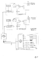
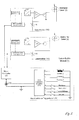
- the Fig. 1 and Fig. 2 1 shows a block diagram of the laser light module 1.
- the laser light module 1 comprises a microcontroller 3, a multifunction trigger cable 20 with plug 21 and for each actuator (marker or illuminator) a laser driver 10 which drives the laser 2.
- the laser driver 10 consists of a highly integrated chip comprising the blocks microcontroller interface 12, an adjustable D / A converter 13, an adjustable logarithmic resistor 14, a temperature sensor 15 and a light power control block 11.
- the microcontroller 3 is on the one hand connected to the microcontroller interface 12 of the laser driver 10 and on the other hand contacted with the plug (21) of the multifunction trigger cable 20.
- the laser light module 1 is operated in the present embodiment in four different laser classes, which are displayed by color different multifunction trigger cable 20 to the user.
- the indoor multi-function trigger cable is white
- the outdoor training trigger cable is blue
- the standard-range combat trigger cable is black
- the multifunction trigger cable is long-range combat
- the built-in port expander module 22 is connected differently. According to this wiring, the microcontroller 3 adjusts the maximum output power of the laser diode 2 of the laser light module 1.
- the port expander module 22 in the multifunction trigger cable has, for example, eight inputs. In the exemplary embodiment, four inputs are used for the discrimination or adjustment of the four laser classes. The other inputs are placed on four buttons of the multi-function trigger cable 20, so that these four buttons of the multi-function trigger cable 20 can be assigned with different functions.
- the inputs of the port expander module 22 are hard-wired or encoded with appropriate resistors and the multifunction trigger cable is marked in the color of the selected laser class for the user. Depending on the color, the first four inputs of the port expander module 22 are connected differently and thereby define the laser class. As a result, the laser light module 1 can be operated by using the corresponding multifunction trigger cable 20 in the associated laser class.
- Fig. 1 Shown in Fig. 1 is a multi-function trigger cable 20, in which the port for expander module 22, the input for "Training 1" is equipped.
- the cable 250 would be marked with blue, for example.
- Fig. 2 shows the laser light module 1 with the trigger cable 20 for setting the laser class "Combat 2". For example, this cable would be marked in gray.
- the microcontroller 3 After switching on the laser light module 1, the microcontroller 3 actively takes the connection with the port expander module 22 in the multifunction trigger cable 20 and reads the desired laser class after successful communication.
- the corresponding calibration values of the laser driver 10 (maximum values for the logarithmic resistor 14 and the D / A converter 13) are stored in the microcontroller 3 and are transmitted to the laser driver 10, so that the maximum laser power is fixed.
- the user or operator can also adjust the power between the maximum allowable power and about 1% by pressing a special trigger button, which is realized by appropriate adjustment of the D / A converter 13.
- the microcontroller 3 monitors that the maximum value is not exceeded and thus the laser class is maintained.
- the microcontroller 3 In the event of a communication error, cable break or other cable defect, the microcontroller 3 always sets the eye-safe laser class "2" (blue) and switches off all active lasers. This ensures safety for the user.
Landscapes
- Engineering & Computer Science (AREA)
- Physics & Mathematics (AREA)
- Optics & Photonics (AREA)
- General Engineering & Computer Science (AREA)
- Radar, Positioning & Navigation (AREA)
- Remote Sensing (AREA)
- Aiming, Guidance, Guns With A Light Source, Armor, Camouflage, And Targets (AREA)
- Laser Surgery Devices (AREA)
- Optical Radar Systems And Details Thereof (AREA)
Abstract
Description
- Die Erfindung beschäftigt sich mit einem Laser-Licht-Modul (LLM) mit einstellbaren, also variablen, Laserklassen. Es wird vorgeschlagen, die Lichtleistung der Aktuatoren von Laser-Licht-Modulen in Abhängigkeit von einem Einsatzszenario rein elektronisch einzustellen, so dass die Umschaltung auf das jeweilige Einsatzszenario ohne Hardware-Umrüstung nunmehr auf elektronischem Wege geschieht. Dazu umfasst das Laser-Licht-Modul zumindest einen steuerbaren Lasertreiber, einen Mikrocontroller und eine Möglichkeit, die Laserklasse einzustellen. Diese Laserklassen des Moduls können dabei über verschiedene Methoden eingestellt werden, z.B. von einem anderen Gerät über eine Schnittstelle, über Tasten durch den Bediener oder ein Muftifunktions-Triggerkabel.
- Laser-Licht-Module dienen als optische Zielhilfen für Handfeuerwaffen. Sie ermöglichen das Anvisieren von Zielen mit einem Rotlicht- und / oder Infrarot-Laserzielmarkierer. Gleichzeitig ist das Beleuchten von Zielen und Zielbereichen im sichtbaren und Infrarot (IR)-Bereich mit Weißlichtlampe und / oder IR-Laser-Beleuchter machbar.
- Aus der
DE 10 2007 022 452 A1 der Anmelderin ist ein Laser-Licht-Modul bekannt, welches wenigstens einen Laser-Zielmarkierer und / oder einen Laser-Zielbeleuchter etc. umfasst. Vorgeschlagen wird, vor wenigstens einer dieser Baugruppen eine optische Linse mit verstellbarer Brennweite einzubinden. Dadurch wird eine variable Fokussierung des Laser-Licht-Moduls erreicht. - Bisherige Lösungen zur Einstellung der Laserleistung sind hardwaremäßig und beschränken sich ausschließlich auf zwei Laserklassen. So werden bei anderen Lasergeräten Filterscheiben mit unterschiedlicher Durchlässigkeit eingesetzt. So kann z.B. ein 5 mW Rotlicht-Laser, der sonst der Laserklasse "3R" entspricht, durch Vorsatz einer Filterscheibe mit 20 % Durchlässigkeit für ein Training mit Laserklasse "2" kleiner 1 mW betrieben werden.
- Bei anderen bekannten Lasergeräten kann zwischen "High-Power" und "Low-Power" umgeschaltet werden. Für den Trainingsbetrieb wird eine mechanische Sperre am Betriebsartenschalter installiert, so dass dieser nicht mehr in die Stellung "High-Power" gedreht werden kann.
- Hier stellt sich die Erfindung die Aufgabe, eine Möglichkeit aufzuzeigen, mit der auch mehr als bisher nur zwei Laserklassen einstellbar sind.
- Gelöst wird die Aufgabe durch die Merkmale des Patentanspruchs 1. Vorteilhafte Ausgestaltungen sind in den Unteransprüchen definiert.
- Der Erfindung liegt die Idee zugrunde, eine Einstellung der Laserklassen elektronisch vorzunehmen.
- Aus der
WO 2011/116 067 A2 ist ein tragbarer Blendungslaser zur Verteidigung bekannt, der eine Laserlichtquelle sowie einen Strahlaufweiter mit verstellbarem Fokus, eine Leistungsquelle, einen Abzug und eine vergrößernde Zielvorrichtung umfasst. Die Vorrichtung weist zudem einen Entfernungsmesser, eine Kamera sowie einen Scharfschalter auf. Das System kann in einer für die Augen unschädliche Weise Angreifer zeitweise das Sehvermögen beeinflussen, so dass die Angreifer geblendet bzw. desorientiert werden. Die Laserlichtquelle kann, je nach Ausführung, ein Laser sein, z.B. Klasse 4, der sehr starkes kohärentes Licht von 1 Watt bis zu 10.000 Watt im sichtbaren Spektrum von etwa 400-800 nm Wellenlänge erzeugt und innerhalb dieser verstellbar ist. - Die
GB 1 269 892 A - Die
WO 2010/141488 A betrifft eine Laser-Blendvorrichtung. Die Vorrichtung besitzt eine Mehrzahl von Steuerschaltkreisen zum Steuern der Laserleistung. - Erfindungsgemäß werden jedoch je nach Einsatzzweck die einzelnen Aktuatoren innerhalb der eingestellten Laserklasse mit unterschiedlichen Ausgangsleistungen konfiguriert und betrieben. Mit den elektronisch einstellbaren Laserklassen können die Geräte flexibler an das jeweilige Einsatzszenario angepasst werden. Es sind dazu keine Hardware-Modifikationen am Gerät notwendig.
- Zur Einstellung der Laserklasse gibt es diverse Möglichkeiten, z.B.:
- ● DIP-Schalter am Gerät
- ● über ein Schnittstelle von einem anderen Gerät
- ● durch Tasten oder Tastenkombinationen
- In der bevorzugten Lösung werden zur Einstellung der Laserklasse austauschbare Multifunktions-Triggerkabel verwendet, in denen die Laserklasse elektronisch kodiert ist und die gemäß der Laserklasse farblich und / oder durch Aufdruck etc. gekennzeichnet sind.
- Das Multifunktions-Triggerkabel besitzt in der bevorzugten Ausführung einen Port-Expander-Baustein mit mehreren Eingängen. Die Einstellung der Laserklasse erfolgt durch fest beschaltete Eingänge des Bausteins. Andere Eingänge des Bausteins sind auf Tasten des Multifunktions-Triggerkabels gelegt, so dass diese mit unterschiedlichen Funktionen belegt werden können. Die Einstellung der Laserleistung innerhalb der vorgegebenen Laserklasse erfolgt durch den Bediener über eine dieser Tasten. So kann z.B. der IR-Beleuchter auf minimale Leistung und der IR-Markierer auf maximale Lichtleistung innerhalb der gewählten Laserklasse eingestellt werden.
- Das Laser-Licht-Modul wird beispielsweise in vier Laserklassen "1", "2", "3R" und "3B" betrieben, wie Indoor-/ Outdoor-Training, Combat für normale Reichweite oder Combat für große Reichweite. In einer bevorzugten Variante werden für die vier Laserklassen vier farblich markierte Multifunktions-Triggerkabel ausgeliefert. Je nach Farbe ist der Porfi-Expander-Baustein im jeweiligen Multifunktions-Triggerkabel unterschiedlich beschaltet. Der Mikrocontroller liest diese Beschaltung ein und stellt die Leistung aller Laser auf die entsprechende Laserklasse ein. Das Laser-Licht-Modul kann so durch Verwendung des entsprechenden Multifunktions-Triggerkabels in die einzelnen Einsatzszenarien geschaltet werden.
- Die elektronische Einstellung der Laserleistung in verschiedenen Laserklassen umfasst in Weiterführung der Erfindung auch die Überwachung und Kontrolle auf Einhaltung der maximal zulässigen Laserleistung der jeweiligen Laserklasse. Ebenfalls wird die variable Einstellung der Laserleistung der einzelnen Aktuatoren im Rahmen der zulässigen Emissionswerte der jeweiligen Laserklasse überwacht und / oder kontrolliert.
- Anhand eines Ausführungsbeispiels mit Zeichnung soll die Erfindung näher erläutert werden.
- Es zeigt:
- Fig. 1
- ein Licht-Laser-Modul mit eingestellter Laserklasse "Training 1"
- Fig. 2
- das Licht-Laser-Modul mit eingestellter Laserklasse "Combat 2"
- Prinzipiell verfügt das Laser-Licht-Modul 1 im bevorzugten Ausführungsbeispiel wenigstens über zwei Zielmarkierer zum Anvisieren von Zielen und einem Zielbeleuchter für das Beleuchten von Zielen und Zielbereichen. Bei zwei Zielmarkierern arbeitet der eine beispielsweise im sichtbaren und der andere im IR-Bereich. Als Zielmarkierer im sichtbaren Wellenlängenbereich können sowohl Rotlicht- als auch Grünlicht-Laser-Module eingesetzt werden. Grünlicht in Laser-Modulen bietet sich an, da grünes Licht vom Auge ca. 10x heller als rotes Licht bei gleicher Lichtleistung empfunden wird. Als Zielbeleuchter des Laser-Licht-Moduls 1 wird neben einer Weißlichtlampe beispielsweise ein IR-Laser eingesetzt, dessen Strahl-Divergenz elektronisch verstellt werden kann. Mit dem Zielmarkierer und dem Zielbeleuchter ist gleichzeitig das Anvisieren und Beleuchten von Zielen und Zielbereichen im sichtbaren und im IR-Bereich möglich.
- Zusätzlich verfügt das Laser-Licht-Modul 1 bevorzugt über einen Abfrage-Laser zur Freund-Identifizierung. Das Laser-Licht-Modul 1 kann damit selbst als Laser-Abfrager in einem "Dismounted Soldier Identification Device (DSID)" verwendet werden. Auch dieser Laser wird elektronisch auf die Leistung der gewählten Laserklasse eingestellt.
- Alle Laser-Module sind in einem gemeinsamen Laserblock integriert und (werksseitig) parallel zueinander ausgerichtet. Diese werden dann bevorzugt mittels Blockjustage gemeinsam zur Waffe parallel justiert, was in Klicks sowohl manuell mit Werkzeug als auch ohne Werkzeug mit Rändelschraube erfolgen kann.
- Die
Fig. 1 undFig. 2 zeigen ein Blockschaltbild des Laser-Licht-Moduls 1. Das Laser-Licht-Modul 1 umfasst einen Mikrocontroller 3, ein Multifunktions-Triggerkabel 20 mit Stecker 21 und für jeden Aktuator (Markierer oder Beleuchter) einen Lasertreiber 10, der den Laser 2 ansteuert. - Der Lasertreiber 10 besteht aus einem hoch integrierten Chip, der die Blöcke Mikrocontroller-Interface 12, einen einstellbaren D/A-Wandler 13, einen einstellbaren logarithmischen Widerstand 14, einen Temperatursensor 15 sowie einen Regelungsblock 11 für die Lichtleistung umfasst.
- Der Mikrocontroller 3 ist einerseits mit dem Mikrocontroller-Interface 12 des Lasertreibers 10 verbunden und andererseits mit dem Stecker (21) des Multifunktions-Triggerkabels 20 kontaktiert.
- Das Laser-Licht-Modul 1 wird in der vorliegenden Ausführung in vier verschiedenen Laserklassen betrieben, die durch farblich unterschiedliche Multifunktions-Triggerkabel 20 dem Nutzer angezeigt werden. Das Multifunktions-Triggerkabel (Indoor-Training) ist beispielsweise weiß, das Multifunktions-Triggerkabel (Outdoor-Training) beispielsweise blau, während das Multifunktions-Triggerkabel (Combat für normale Reichweite) die schwarze Farbe hat und das Multifunktions-Triggerkabel (Combat für große Reichweite) grau ist. Je nach Farbe, Aufdruck etc. ist der eingebaute Port-Expander-Baustein 22 verschieden beschaltet. Gemäß dieser Beschaltung stellt der Mikrocontroller 3 die maximale Ausgangsleistung der LaserDiode 2 des Laser-Licht-Moduls 1 ein.
- Der Port-Expander-Baustein 22 im Multifunktions-Triggerkabel hat beispielsweise acht Eingänge. Im Ausführungsbeispiel werden vier Eingänge für die Unterscheidung bzw. Einstellung der vier Laserklassen verwendet. Die anderen Eingänge sind auf vier Tasten des Multifunktions-Triggerkabels 20 gelegt, so dass diese vier Tasten des Multifunktions-Triggerkabels 20 mit unterschiedlichen Funktionen belegt werden können. Zur Einstellung der Laserklassen werden die Eingänge des Port-Expander-Bausteins 22 mit entsprechenden Widerständen fest beschaltet bzw. kodiert und das Multifunktions-Triggerkabel in der Farbe der gewählten Laserklasse für den Nutzer gekennzeichnet. Je nach Farbe sind die ersten vier Eingänge des Port-Expander-Bausteins 22 unterschiedlich beschaltet und legen damit die Laserklasse fest. Dadurch kann das Laser-Licht-Modul 1 durch Verwendung des entsprechenden Multifunktions-Triggerkabels 20 in der zugeordneten Laserklasse betrieben werden.
- Dargestellt in
Fig. 1 ist ein Multifunktions-Triggerkabel 20, in welchem am Port-Expander-Baustein 22 der Eingang für "Training 1" bestückt ist. Das Kabel 250 wäre dafür beispielsweise mit blau gekennzeichnet.Fig. 2 zeigt das Laser-Licht-Modul 1 mit dem Triggerkabel 20 zum Einstellen der Laserklasse "Combat 2". Dieses Kabel wäre beispielsweise mit grau gekennzeichnet. - Nach dem Einschalten des Laser-Licht-Moduls 1 nimmt der Mikrocontroller 3 aktiv die Verbindung mit dem Port-Expander-Baustein 22 im Multifunktions-Triggerkabel 20 auf und liest nach erfolgreicher Kommunikation die gewünschte Laserklasse aus. Die entsprechenden Kalibrierwerte des Lasertreibers 10 (Maximalwerte für den logarithmischen Widerstand 14 und den D/A-Wandler 13) sind im Mikrocontroller 3 hinterlegt und werden dem Lasertreiber 10 übermittelt, so dass die maximale Laserleistung festgelegt ist. Der Nutzer oder Bediener kann durch Betätigen einer speziellen Triggertaste zusätzlich die Leistung zwischen der maximal zulässigen Leistung und etwa 1 % verstellen, was durch entsprechende Einstellung des D/A-Wandlers 13 realisiert wird. Der Mikrocontroller 3 überwacht, dass der Maximalwert nicht überschritten und damit die Laserklasse eingehalten wird.
- Bei Kommunikationsfehler, Kabelbruch oder sonstigem Kabeldefekt wird vom Mikrocontroller 3 immer die augensichere Laserklasse "2" (blau) eingestellt und alle aktiven Laser ausgeschaltet. Dadurch wird die Sicherheit für den Benutzer gewährleistet.
Claims (9)
- Laser-Licht-Modul (1) mit wenigstens einem Zielmarkierer zum Anvisieren von Zielen und einem Zielbeleuchter für das Beleuchten von Zielen und Zielbereichen, dadurch gekennzeichnet, dass das Laser-Licht-Modul (1) einen steuerbaren Lasertreiber (10) und einen Mikrocontroller (3) zur rein elektronischen Einstellung verschiedene Laserklassen des Laser-Licht-Moduls (1) umfasst, wobei der Mikrocontroller (3) die Leistung aller Laser regelt und überwacht, sodass Grenzwerte der eingestellten Laserklasse nicht überschritten werden.
- Laser-Licht-Modul (1) nach Anspruch 1, dadurch gekennzeichnet, dass ein austauschbares Multifunktions-Triggerkabel (20) eingebunden ist, in denen die Laserklasse elektronisch kodiert ist.
- Laser-Licht-Modul (1) nach Anspruch 2, dadurch gekennzeichnet, dass das austauschbare Multifunktions-Triggerkabel (20) farblich und / oder durch Aufdruck, Kerbungen oder dergleichen gekennzeichnet sind.
- Laser-Licht-Modul (1) nach Anspruch 2 oder 3, dadurch gekennzeichnet, dass das Multifunktions-Triggerkabel (20) eine oder mehrere Tasten des zum Ein-/Ausschalten der Laser besitzt.
- Laser-Licht-Modul (1) nach Anspruch 4, dadurch gekennzeichnet, dass über eine Taste der Nutzer die Leistung der Laser innerhalb der eingestellten Laserklasse verstellen kann.
- Laser-Licht-Modul (1) nach Anspruch 1, dadurch gekennzeichnet, dass das Licht-Laser-Modul (1) einen DIP-Schalter und / oder eine Schnittstelle umfasst.
- Laser-Licht-Modul (1) gemäß einem der Ansprüche 1 bis 5, dadurch gekennzeichnet, dass das Laser-Licht-Modul (1) über einen Abfrage-Laser zur Freund-Identifizierung verfügt.
- Laser-Licht-Modul (1) nach Anspruch 6, dadurch gekennzeichnet, dass die Leistung des Abfrage-Lasers zur Freund-Identifizierung elektronisch gemäß der gewählten Laserklasse eingestellt wird.
- Laser-Licht-Modul nach einem oder mehreren der Ansprüche 1 bis 7, dadurch gekenn zeichnet, dass der Zielbeleuchter ein Laser mit elektronisch verstellbarer Strahlbreite ist.
Applications Claiming Priority (1)
| Application Number | Priority Date | Filing Date | Title |
|---|---|---|---|
| DE102012001993A DE102012001993A1 (de) | 2012-02-03 | 2012-02-03 | Laser-Licht-Modul mit elektronisch einstellbaren Laserklassen |
Publications (3)
| Publication Number | Publication Date |
|---|---|
| EP2623919A2 true EP2623919A2 (de) | 2013-08-07 |
| EP2623919A3 EP2623919A3 (de) | 2015-03-25 |
| EP2623919B1 EP2623919B1 (de) | 2016-07-13 |
Family
ID=47709913
Family Applications (1)
| Application Number | Title | Priority Date | Filing Date |
|---|---|---|---|
| EP13153535.3A Active EP2623919B1 (de) | 2012-02-03 | 2013-01-31 | Laser-Licht-Modul mit elektronisch einstellbaren Laserklassen |
Country Status (2)
| Country | Link |
|---|---|
| EP (1) | EP2623919B1 (de) |
| DE (1) | DE102012001993A1 (de) |
Citations (4)
| Publication number | Priority date | Publication date | Assignee | Title |
|---|---|---|---|---|
| GB1269892A (en) | 1969-03-20 | 1972-04-06 | Messerschmitt Boelkow Blohm | Weapon system for the detection of and use against stationary or moving objects |
| DE102007022452A1 (de) | 2007-05-10 | 2008-11-13 | Oerlikon Contraves Gmbh | Modul, insbesondere Laser-/ Licht- Modul mit variabler Fokussierung |
| WO2010141488A1 (en) | 2009-06-01 | 2010-12-09 | Laser Energetics Inc. | Laser dazing baton shaped optical distractor and searchlight |
| WO2011116067A2 (en) | 2010-03-16 | 2011-09-22 | Xtreme Ads Limited | Dazzling laser rifle |
Family Cites Families (2)
| Publication number | Priority date | Publication date | Assignee | Title |
|---|---|---|---|---|
| US6363648B1 (en) * | 2000-01-27 | 2002-04-02 | William H. Grube | Laser aiming light for firearms |
| US7308202B2 (en) * | 2002-02-01 | 2007-12-11 | Cubic Corporation | Secure covert combat identification friend-or-foe (IFF) system for the dismounted soldier |
-
2012
- 2012-02-03 DE DE102012001993A patent/DE102012001993A1/de not_active Ceased
-
2013
- 2013-01-31 EP EP13153535.3A patent/EP2623919B1/de active Active
Patent Citations (4)
| Publication number | Priority date | Publication date | Assignee | Title |
|---|---|---|---|---|
| GB1269892A (en) | 1969-03-20 | 1972-04-06 | Messerschmitt Boelkow Blohm | Weapon system for the detection of and use against stationary or moving objects |
| DE102007022452A1 (de) | 2007-05-10 | 2008-11-13 | Oerlikon Contraves Gmbh | Modul, insbesondere Laser-/ Licht- Modul mit variabler Fokussierung |
| WO2010141488A1 (en) | 2009-06-01 | 2010-12-09 | Laser Energetics Inc. | Laser dazing baton shaped optical distractor and searchlight |
| WO2011116067A2 (en) | 2010-03-16 | 2011-09-22 | Xtreme Ads Limited | Dazzling laser rifle |
Also Published As
| Publication number | Publication date |
|---|---|
| DE102012001993A1 (de) | 2013-08-08 |
| EP2623919B1 (de) | 2016-07-13 |
| EP2623919A3 (de) | 2015-03-25 |
Similar Documents
| Publication | Publication Date | Title |
|---|---|---|
| DE69213407T2 (de) | Waffenvisiersystem | |
| EP0945697B1 (de) | Identifikationssystem | |
| DE69702140T2 (de) | Verfahren und gerät zum verbessern der taktilen empfindlichkeit des schützen beim schiesssport | |
| DE4444636A1 (de) | Waffensystem für einen Blendlaser | |
| DE2942816A1 (de) | Zielgeraet fuer waffen | |
| DE102013102826A1 (de) | Zielfernrohr | |
| EP2706407A2 (de) | Objektiv- und Kamera-Fernsteuereinheit | |
| WO2003087718A1 (de) | ENTFERNUNGSMEβGERÄT | |
| DE102017100068A1 (de) | Lasersystem mit Schutzeinrichtung | |
| DE10354714A1 (de) | Fahrzeugscheinwerfer und Verfahren zum Betreiben eines Fahrzeugscheinwerfers | |
| EP2926087A1 (de) | Zielobjekt für ein lasermessgerät und verfahren zum identifizieren des zielobjektes | |
| EP2623919B1 (de) | Laser-Licht-Modul mit elektronisch einstellbaren Laserklassen | |
| DE102019111973B4 (de) | Handwerkzeugmaschine, insbesondere Akku-Schrauber oder Akku-Bohrer | |
| DE102005054156B4 (de) | Justiervorrichtung und Verfahren zur Ausrichtung der Simulatorachse eines mit einer Waffe verbundenen Schusssimulators | |
| EP3042143B1 (de) | Handfeuerwaffe mit einem zielmittel | |
| EP1645833B1 (de) | Visiervorrichtung für eine Schusswaffe und Schusswaffe mit einer Montagemöglichkeit für eine Visiervorrichtung | |
| EP1154284A1 (de) | Multifunkionelle optische Zielvorrichtung | |
| EP0859243B1 (de) | Laseridentifikationssystem | |
| EP3488174A1 (de) | Schusswaffe sowie verfahren zur verbesserung der treffsicherheit | |
| EP3348953A1 (de) | Vorrichtung zum ermitteln der treffsicherheit eines schützen | |
| DE102009040280A1 (de) | Modulare Justiervorrichtung zur parallelen Ausrichtung der Simulatorachse eines Schusssimulators zur Visierlinie einer Schusswaffe | |
| DE102020116897B4 (de) | Laserprojektor mit zwei Laserdioden | |
| DE102004011905B4 (de) | Photovoltaisches Target für Schießanwendungen | |
| DE102017007837A1 (de) | Nicht-letales Wirkmittel | |
| DE3545830C2 (de) |
Legal Events
| Date | Code | Title | Description |
|---|---|---|---|
| PUAI | Public reference made under article 153(3) epc to a published international application that has entered the european phase |
Free format text: ORIGINAL CODE: 0009012 |
|
| AK | Designated contracting states |
Kind code of ref document: A2 Designated state(s): AL AT BE BG CH CY CZ DE DK EE ES FI FR GB GR HR HU IE IS IT LI LT LU LV MC MK MT NL NO PL PT RO RS SE SI SK SM TR |
|
| AX | Request for extension of the european patent |
Extension state: BA ME |
|
| PUAL | Search report despatched |
Free format text: ORIGINAL CODE: 0009013 |
|
| AK | Designated contracting states |
Kind code of ref document: A3 Designated state(s): AL AT BE BG CH CY CZ DE DK EE ES FI FR GB GR HR HU IE IS IT LI LT LU LV MC MK MT NL NO PL PT RO RS SE SI SK SM TR |
|
| AX | Request for extension of the european patent |
Extension state: BA ME |
|
| RIC1 | Information provided on ipc code assigned before grant |
Ipc: F41H 13/00 20060101ALN20150216BHEP Ipc: F41G 1/35 20060101AFI20150216BHEP Ipc: F41G 1/473 20060101ALN20150216BHEP |
|
| 17P | Request for examination filed |
Effective date: 20150922 |
|
| RBV | Designated contracting states (corrected) |
Designated state(s): AL AT BE BG CH CY CZ DE DK EE ES FI FR GB GR HR HU IE IS IT LI LT LU LV MC MK MT NL NO PL PT RO RS SE SI SK SM TR |
|
| GRAP | Despatch of communication of intention to grant a patent |
Free format text: ORIGINAL CODE: EPIDOSNIGR1 |
|
| RIC1 | Information provided on ipc code assigned before grant |
Ipc: F41G 1/473 20060101ALN20151216BHEP Ipc: F41H 13/00 20060101ALN20151216BHEP Ipc: F41G 1/35 20060101AFI20151216BHEP |
|
| INTG | Intention to grant announced |
Effective date: 20160119 |
|
| RIN1 | Information on inventor provided before grant (corrected) |
Inventor name: SIEBER, WINFRIED Inventor name: HUTTNY, GEORG Inventor name: MUELLER, JUERGEN Inventor name: KRUEGER, THOMAS Inventor name: GAISSNER, ALEXANDER |
|
| RAP1 | Party data changed (applicant data changed or rights of an application transferred) |
Owner name: RHEINMETALL SOLDIER ELECTRONICS GMBH |
|
| GRAS | Grant fee paid |
Free format text: ORIGINAL CODE: EPIDOSNIGR3 |
|
| GRAA | (expected) grant |
Free format text: ORIGINAL CODE: 0009210 |
|
| AK | Designated contracting states |
Kind code of ref document: B1 Designated state(s): AL AT BE BG CH CY CZ DE DK EE ES FI FR GB GR HR HU IE IS IT LI LT LU LV MC MK MT NL NO PL PT RO RS SE SI SK SM TR |
|
| REG | Reference to a national code |
Ref country code: GB Ref legal event code: FG4D Free format text: NOT ENGLISH |
|
| REG | Reference to a national code |
Ref country code: AT Ref legal event code: REF Ref document number: 812701 Country of ref document: AT Kind code of ref document: T Effective date: 20160715 Ref country code: CH Ref legal event code: EP |
|
| REG | Reference to a national code |
Ref country code: IE Ref legal event code: FG4D Free format text: LANGUAGE OF EP DOCUMENT: GERMAN |
|
| REG | Reference to a national code |
Ref country code: DE Ref legal event code: R096 Ref document number: 502013003654 Country of ref document: DE |
|
| REG | Reference to a national code |
Ref country code: LT Ref legal event code: MG4D |
|
| REG | Reference to a national code |
Ref country code: NL Ref legal event code: MP Effective date: 20160713 |
|
| PG25 | Lapsed in a contracting state [announced via postgrant information from national office to epo] |
Ref country code: IS Free format text: LAPSE BECAUSE OF FAILURE TO SUBMIT A TRANSLATION OF THE DESCRIPTION OR TO PAY THE FEE WITHIN THE PRESCRIBED TIME-LIMIT Effective date: 20161113 Ref country code: HR Free format text: LAPSE BECAUSE OF FAILURE TO SUBMIT A TRANSLATION OF THE DESCRIPTION OR TO PAY THE FEE WITHIN THE PRESCRIBED TIME-LIMIT Effective date: 20160713 Ref country code: IT Free format text: LAPSE BECAUSE OF FAILURE TO SUBMIT A TRANSLATION OF THE DESCRIPTION OR TO PAY THE FEE WITHIN THE PRESCRIBED TIME-LIMIT Effective date: 20160713 Ref country code: NL Free format text: LAPSE BECAUSE OF FAILURE TO SUBMIT A TRANSLATION OF THE DESCRIPTION OR TO PAY THE FEE WITHIN THE PRESCRIBED TIME-LIMIT Effective date: 20160713 Ref country code: LT Free format text: LAPSE BECAUSE OF FAILURE TO SUBMIT A TRANSLATION OF THE DESCRIPTION OR TO PAY THE FEE WITHIN THE PRESCRIBED TIME-LIMIT Effective date: 20160713 Ref country code: NO Free format text: LAPSE BECAUSE OF FAILURE TO SUBMIT A TRANSLATION OF THE DESCRIPTION OR TO PAY THE FEE WITHIN THE PRESCRIBED TIME-LIMIT Effective date: 20161013 Ref country code: RS Free format text: LAPSE BECAUSE OF FAILURE TO SUBMIT A TRANSLATION OF THE DESCRIPTION OR TO PAY THE FEE WITHIN THE PRESCRIBED TIME-LIMIT Effective date: 20160713 Ref country code: FI Free format text: LAPSE BECAUSE OF FAILURE TO SUBMIT A TRANSLATION OF THE DESCRIPTION OR TO PAY THE FEE WITHIN THE PRESCRIBED TIME-LIMIT Effective date: 20160713 |
|
| PG25 | Lapsed in a contracting state [announced via postgrant information from national office to epo] |
Ref country code: GR Free format text: LAPSE BECAUSE OF FAILURE TO SUBMIT A TRANSLATION OF THE DESCRIPTION OR TO PAY THE FEE WITHIN THE PRESCRIBED TIME-LIMIT Effective date: 20161014 Ref country code: LV Free format text: LAPSE BECAUSE OF FAILURE TO SUBMIT A TRANSLATION OF THE DESCRIPTION OR TO PAY THE FEE WITHIN THE PRESCRIBED TIME-LIMIT Effective date: 20160713 Ref country code: ES Free format text: LAPSE BECAUSE OF FAILURE TO SUBMIT A TRANSLATION OF THE DESCRIPTION OR TO PAY THE FEE WITHIN THE PRESCRIBED TIME-LIMIT Effective date: 20160713 Ref country code: PT Free format text: LAPSE BECAUSE OF FAILURE TO SUBMIT A TRANSLATION OF THE DESCRIPTION OR TO PAY THE FEE WITHIN THE PRESCRIBED TIME-LIMIT Effective date: 20161114 Ref country code: SE Free format text: LAPSE BECAUSE OF FAILURE TO SUBMIT A TRANSLATION OF THE DESCRIPTION OR TO PAY THE FEE WITHIN THE PRESCRIBED TIME-LIMIT Effective date: 20160713 |
|
| REG | Reference to a national code |
Ref country code: DE Ref legal event code: R097 Ref document number: 502013003654 Country of ref document: DE |
|
| PG25 | Lapsed in a contracting state [announced via postgrant information from national office to epo] |
Ref country code: RO Free format text: LAPSE BECAUSE OF FAILURE TO SUBMIT A TRANSLATION OF THE DESCRIPTION OR TO PAY THE FEE WITHIN THE PRESCRIBED TIME-LIMIT Effective date: 20160713 Ref country code: EE Free format text: LAPSE BECAUSE OF FAILURE TO SUBMIT A TRANSLATION OF THE DESCRIPTION OR TO PAY THE FEE WITHIN THE PRESCRIBED TIME-LIMIT Effective date: 20160713 |
|
| PLBE | No opposition filed within time limit |
Free format text: ORIGINAL CODE: 0009261 |
|
| STAA | Information on the status of an ep patent application or granted ep patent |
Free format text: STATUS: NO OPPOSITION FILED WITHIN TIME LIMIT |
|
| PG25 | Lapsed in a contracting state [announced via postgrant information from national office to epo] |
Ref country code: SK Free format text: LAPSE BECAUSE OF FAILURE TO SUBMIT A TRANSLATION OF THE DESCRIPTION OR TO PAY THE FEE WITHIN THE PRESCRIBED TIME-LIMIT Effective date: 20160713 Ref country code: BG Free format text: LAPSE BECAUSE OF FAILURE TO SUBMIT A TRANSLATION OF THE DESCRIPTION OR TO PAY THE FEE WITHIN THE PRESCRIBED TIME-LIMIT Effective date: 20161013 Ref country code: PL Free format text: LAPSE BECAUSE OF FAILURE TO SUBMIT A TRANSLATION OF THE DESCRIPTION OR TO PAY THE FEE WITHIN THE PRESCRIBED TIME-LIMIT Effective date: 20160713 Ref country code: DK Free format text: LAPSE BECAUSE OF FAILURE TO SUBMIT A TRANSLATION OF THE DESCRIPTION OR TO PAY THE FEE WITHIN THE PRESCRIBED TIME-LIMIT Effective date: 20160713 Ref country code: SM Free format text: LAPSE BECAUSE OF FAILURE TO SUBMIT A TRANSLATION OF THE DESCRIPTION OR TO PAY THE FEE WITHIN THE PRESCRIBED TIME-LIMIT Effective date: 20160713 Ref country code: BE Free format text: LAPSE BECAUSE OF NON-PAYMENT OF DUE FEES Effective date: 20170131 Ref country code: CZ Free format text: LAPSE BECAUSE OF FAILURE TO SUBMIT A TRANSLATION OF THE DESCRIPTION OR TO PAY THE FEE WITHIN THE PRESCRIBED TIME-LIMIT Effective date: 20160713 |
|
| 26N | No opposition filed |
Effective date: 20170418 |
|
| PG25 | Lapsed in a contracting state [announced via postgrant information from national office to epo] |
Ref country code: SI Free format text: LAPSE BECAUSE OF FAILURE TO SUBMIT A TRANSLATION OF THE DESCRIPTION OR TO PAY THE FEE WITHIN THE PRESCRIBED TIME-LIMIT Effective date: 20160713 |
|
| REG | Reference to a national code |
Ref country code: CH Ref legal event code: PL |
|
| PG25 | Lapsed in a contracting state [announced via postgrant information from national office to epo] |
Ref country code: MC Free format text: LAPSE BECAUSE OF FAILURE TO SUBMIT A TRANSLATION OF THE DESCRIPTION OR TO PAY THE FEE WITHIN THE PRESCRIBED TIME-LIMIT Effective date: 20160713 |
|
| REG | Reference to a national code |
Ref country code: FR Ref legal event code: ST Effective date: 20170929 |
|
| PG25 | Lapsed in a contracting state [announced via postgrant information from national office to epo] |
Ref country code: FR Free format text: LAPSE BECAUSE OF NON-PAYMENT OF DUE FEES Effective date: 20170131 Ref country code: CH Free format text: LAPSE BECAUSE OF NON-PAYMENT OF DUE FEES Effective date: 20170131 Ref country code: LI Free format text: LAPSE BECAUSE OF NON-PAYMENT OF DUE FEES Effective date: 20170131 |
|
| REG | Reference to a national code |
Ref country code: IE Ref legal event code: MM4A |
|
| PG25 | Lapsed in a contracting state [announced via postgrant information from national office to epo] |
Ref country code: LU Free format text: LAPSE BECAUSE OF NON-PAYMENT OF DUE FEES Effective date: 20170131 |
|
| REG | Reference to a national code |
Ref country code: BE Ref legal event code: MM Effective date: 20170131 |
|
| PG25 | Lapsed in a contracting state [announced via postgrant information from national office to epo] |
Ref country code: IE Free format text: LAPSE BECAUSE OF NON-PAYMENT OF DUE FEES Effective date: 20170131 |
|
| PG25 | Lapsed in a contracting state [announced via postgrant information from national office to epo] |
Ref country code: MT Free format text: LAPSE BECAUSE OF FAILURE TO SUBMIT A TRANSLATION OF THE DESCRIPTION OR TO PAY THE FEE WITHIN THE PRESCRIBED TIME-LIMIT Effective date: 20160713 |
|
| PG25 | Lapsed in a contracting state [announced via postgrant information from national office to epo] |
Ref country code: AL Free format text: LAPSE BECAUSE OF FAILURE TO SUBMIT A TRANSLATION OF THE DESCRIPTION OR TO PAY THE FEE WITHIN THE PRESCRIBED TIME-LIMIT Effective date: 20160713 |
|
| REG | Reference to a national code |
Ref country code: AT Ref legal event code: MM01 Ref document number: 812701 Country of ref document: AT Kind code of ref document: T Effective date: 20180131 |
|
| PG25 | Lapsed in a contracting state [announced via postgrant information from national office to epo] |
Ref country code: AT Free format text: LAPSE BECAUSE OF NON-PAYMENT OF DUE FEES Effective date: 20180131 |
|
| PG25 | Lapsed in a contracting state [announced via postgrant information from national office to epo] |
Ref country code: HU Free format text: LAPSE BECAUSE OF FAILURE TO SUBMIT A TRANSLATION OF THE DESCRIPTION OR TO PAY THE FEE WITHIN THE PRESCRIBED TIME-LIMIT; INVALID AB INITIO Effective date: 20130131 |
|
| PG25 | Lapsed in a contracting state [announced via postgrant information from national office to epo] |
Ref country code: CY Free format text: LAPSE BECAUSE OF NON-PAYMENT OF DUE FEES Effective date: 20160713 |
|
| PG25 | Lapsed in a contracting state [announced via postgrant information from national office to epo] |
Ref country code: MK Free format text: LAPSE BECAUSE OF FAILURE TO SUBMIT A TRANSLATION OF THE DESCRIPTION OR TO PAY THE FEE WITHIN THE PRESCRIBED TIME-LIMIT Effective date: 20160713 |
|
| PG25 | Lapsed in a contracting state [announced via postgrant information from national office to epo] |
Ref country code: TR Free format text: LAPSE BECAUSE OF FAILURE TO SUBMIT A TRANSLATION OF THE DESCRIPTION OR TO PAY THE FEE WITHIN THE PRESCRIBED TIME-LIMIT Effective date: 20160713 |
|
| REG | Reference to a national code |
Ref country code: DE Ref legal event code: R082 Ref document number: 502013003654 Country of ref document: DE Representative=s name: HUEBSCH, KIRSCHNER & PARTNER, PATENTANWAELTE U, DE Ref country code: DE Ref legal event code: R082 Ref document number: 502013003654 Country of ref document: DE Representative=s name: HUEBSCH & KIRSCHNER PARTNERSCHAFT, PATENTANWAE, DE |
|
| PGFP | Annual fee paid to national office [announced via postgrant information from national office to epo] |
Ref country code: GB Payment date: 20260123 Year of fee payment: 14 |
|
| PGFP | Annual fee paid to national office [announced via postgrant information from national office to epo] |
Ref country code: DE Payment date: 20260121 Year of fee payment: 14 |