EP2624263A2 - Commande électrique pour électroaimants - Google Patents
Commande électrique pour électroaimants Download PDFInfo
- Publication number
- EP2624263A2 EP2624263A2 EP12008466.0A EP12008466A EP2624263A2 EP 2624263 A2 EP2624263 A2 EP 2624263A2 EP 12008466 A EP12008466 A EP 12008466A EP 2624263 A2 EP2624263 A2 EP 2624263A2
- Authority
- EP
- European Patent Office
- Prior art keywords
- electrical
- control
- signal
- current
- control unit
- Prior art date
- Legal status (The legal status is an assumption and is not a legal conclusion. Google has not performed a legal analysis and makes no representation as to the accuracy of the status listed.)
- Granted
Links
Images


Classifications
-
- H—ELECTRICITY
- H01—ELECTRIC ELEMENTS
- H01F—MAGNETS; INDUCTANCES; TRANSFORMERS; SELECTION OF MATERIALS FOR THEIR MAGNETIC PROPERTIES
- H01F7/00—Magnets
- H01F7/06—Electromagnets; Actuators including electromagnets
- H01F7/08—Electromagnets; Actuators including electromagnets with armatures
- H01F7/18—Circuit arrangements for obtaining desired operating characteristics, e.g. for slow operation, for sequential energisation of windings, for high-speed energisation of windings
- H01F7/1844—Monitoring or fail-safe circuits
-
- F—MECHANICAL ENGINEERING; LIGHTING; HEATING; WEAPONS; BLASTING
- F02—COMBUSTION ENGINES; HOT-GAS OR COMBUSTION-PRODUCT ENGINE PLANTS
- F02D—CONTROLLING COMBUSTION ENGINES
- F02D41/00—Electrical control of supply of combustible mixture or its constituents
- F02D41/20—Output circuits, e.g. for controlling currents in command coils
-
- F—MECHANICAL ENGINEERING; LIGHTING; HEATING; WEAPONS; BLASTING
- F02—COMBUSTION ENGINES; HOT-GAS OR COMBUSTION-PRODUCT ENGINE PLANTS
- F02D—CONTROLLING COMBUSTION ENGINES
- F02D41/00—Electrical control of supply of combustible mixture or its constituents
- F02D41/22—Safety or indicating devices for abnormal conditions
-
- F—MECHANICAL ENGINEERING; LIGHTING; HEATING; WEAPONS; BLASTING
- F02—COMBUSTION ENGINES; HOT-GAS OR COMBUSTION-PRODUCT ENGINE PLANTS
- F02D—CONTROLLING COMBUSTION ENGINES
- F02D41/00—Electrical control of supply of combustible mixture or its constituents
- F02D41/22—Safety or indicating devices for abnormal conditions
- F02D41/222—Safety or indicating devices for abnormal conditions relating to the failure of sensors or parameter detection devices
-
- H—ELECTRICITY
- H01—ELECTRIC ELEMENTS
- H01F—MAGNETS; INDUCTANCES; TRANSFORMERS; SELECTION OF MATERIALS FOR THEIR MAGNETIC PROPERTIES
- H01F7/00—Magnets
- H01F7/06—Electromagnets; Actuators including electromagnets
- H01F7/08—Electromagnets; Actuators including electromagnets with armatures
- H01F7/18—Circuit arrangements for obtaining desired operating characteristics, e.g. for slow operation, for sequential energisation of windings, for high-speed energisation of windings
- H01F7/1877—Circuit arrangements for obtaining desired operating characteristics, e.g. for slow operation, for sequential energisation of windings, for high-speed energisation of windings controlling a plurality of loads
-
- F—MECHANICAL ENGINEERING; LIGHTING; HEATING; WEAPONS; BLASTING
- F02—COMBUSTION ENGINES; HOT-GAS OR COMBUSTION-PRODUCT ENGINE PLANTS
- F02D—CONTROLLING COMBUSTION ENGINES
- F02D41/00—Electrical control of supply of combustible mixture or its constituents
- F02D41/20—Output circuits, e.g. for controlling currents in command coils
- F02D2041/202—Output circuits, e.g. for controlling currents in command coils characterised by the control of the circuit
- F02D2041/2051—Output circuits, e.g. for controlling currents in command coils characterised by the control of the circuit using voltage control
-
- F—MECHANICAL ENGINEERING; LIGHTING; HEATING; WEAPONS; BLASTING
- F02—COMBUSTION ENGINES; HOT-GAS OR COMBUSTION-PRODUCT ENGINE PLANTS
- F02D—CONTROLLING COMBUSTION ENGINES
- F02D41/00—Electrical control of supply of combustible mixture or its constituents
- F02D41/20—Output circuits, e.g. for controlling currents in command coils
- F02D2041/202—Output circuits, e.g. for controlling currents in command coils characterised by the control of the circuit
- F02D2041/2058—Output circuits, e.g. for controlling currents in command coils characterised by the control of the circuit using information of the actual current value
-
- H—ELECTRICITY
- H01—ELECTRIC ELEMENTS
- H01F—MAGNETS; INDUCTANCES; TRANSFORMERS; SELECTION OF MATERIALS FOR THEIR MAGNETIC PROPERTIES
- H01F7/00—Magnets
- H01F7/06—Electromagnets; Actuators including electromagnets
- H01F7/08—Electromagnets; Actuators including electromagnets with armatures
- H01F7/18—Circuit arrangements for obtaining desired operating characteristics, e.g. for slow operation, for sequential energisation of windings, for high-speed energisation of windings
- H01F7/1844—Monitoring or fail-safe circuits
- H01F2007/1861—Monitoring or fail-safe circuits using derivative of measured variable
-
- Y—GENERAL TAGGING OF NEW TECHNOLOGICAL DEVELOPMENTS; GENERAL TAGGING OF CROSS-SECTIONAL TECHNOLOGIES SPANNING OVER SEVERAL SECTIONS OF THE IPC; TECHNICAL SUBJECTS COVERED BY FORMER USPC CROSS-REFERENCE ART COLLECTIONS [XRACs] AND DIGESTS
- Y02—TECHNOLOGIES OR APPLICATIONS FOR MITIGATION OR ADAPTATION AGAINST CLIMATE CHANGE
- Y02T—CLIMATE CHANGE MITIGATION TECHNOLOGIES RELATED TO TRANSPORTATION
- Y02T10/00—Road transport of goods or passengers
- Y02T10/10—Internal combustion engine [ICE] based vehicles
- Y02T10/40—Engine management systems
Definitions
- the invention relates to an electrical control for an electromagnet according to the preamble of the first claim.
- Electromagnets are known and widely used. They are mainly used to deliver a regulated electric current to an electromagnet in response to an input signal.
- the force of an electromagnet is proportional to the current through its coil. If one acts on the coil with a regulated current, one can adjust the force of the electromagnet without further measures. This is particularly advantageous in the control of valves, but one uses this context even with proportional magnets for other applications, for example in transmissions.
- An electronic unit integrated in the magnet is in DE 10 2007 019 619 described.
- Such integrated or attachable electrical controls are designed for interaction with an electromagnet.
- many devices actuated by such magnets have two magnets which must cooperate meaningfully.
- the known electrical controls provide little or no protection against inadmissible output currents in case of malfunction of the programmable logic controller or the current controller.
- Such monitoring may be performed by a higher level electrical controller.
- two drives monitor each other. In both cases, it is necessary to measure the current flowing to the magnet electric current and transmit the measurement signal thus obtained even in the case of a serious malfunction of the programmable logic controller to the monitoring controller.
- the electrical control for electromagnets with a programmable electronic control unit, with a connection for connection of the control to an electromagnet, a first connector for connecting the control to a higher-level electrical control unit or to an electromechanical signal generator, with a electrical power control device and equipped with the necessary connecting lines for supplying an electromagnet with a regulated electric current.
- a further plug connection has a contact for the line which is connected to a current measuring device contained in the electrical control and which conducts an outgoing analog voltage signal which is proportional to the electrical current delivered to the electromagnet.
- the second connector has another contact for another line, which conducts an input signal, one in the electrical Actuation applied to existing electronic switch and thus switches off the electric current for the electromagnet.
- two electromagnets and two controls are used according to the invention for the operation of a device that monitor each other with respect to the error-free operation by exchanging analog signals on the output electric currents to the electromagnets and turn off the currents to the electromagnet in case of error.
- the information about the output to the electromagnets electrical currents are transmitted analogously to two lines.
- the switching signals for interrupting the currents are transmitted via another line.
- To interrupt the currents from the electrical controls to the associated electromagnets is a common line.
- the signal inputs to this line are linked by the Wired Or function, with an active signal on the line opening the switches.
- the interruption is made by electronic switches.
- the information about the nominal values of the currents is transmitted between the control units via a digital data bus connected to a multi-core cable.
- the electrical control is connected to a superordinate electrical control unit by a first multi-core cable and with its associated second control with a second multi-core cable.
- the signals from the higher-level control unit for the first control are forwarded in the mode of a digital bus via the second cable for the second control.
- the higher-level electrical control unit participates in the fault monitoring and, if necessary, extends it by monitoring the device actuated by the electromagnets by means of a sensor and contradicting them with respect to the control commands
- the power supply of the magnets is interrupted. The interruption is made by opening the electronic switches by a switching signal via the separate line described above.
- the inclusion of the higher-level electrical control unit nevertheless improves the reliability of the fault detection by passing the analog signals which describe the currents with additional lines to the higher-level control. Here they are compared with the setpoints and with different messages from the electrical controls, a decision is made as to which message is correct. Thus, the frequency of shutdowns due to erroneous evaluations can be reduced.
- only one electric drive is connected to a higher-level electrical control unit via a digital electrical bus, via a line for an analog signal and via a further line for a switching function.
- the higher-level electrical control unit predefines the desired value of the current to the electromagnet via the digital bus and checks the conversion of the specification by means of the analog signal. In the event of an error detected in the current regulation, the higher-level control unit switches off the current of the electrical control via the electronic switch by means of a switching signal.
- no higher-level electrical control unit is provided, but the electrical control, as well as a further control, are electrically connected to an electro-mechanical signal generator, which emits the same or complementary signals to the two actuators.
- the signal transmission from the signal generator to the controls can be analog or digital, optionally via a digital bus.
- the signal transmission by analog signals they are preferably complementary, the signal for the first electrical drive increases when the signal to the second electrical control drops.
- Each drive generates an electrical current for the associated electromagnet in accordance with the signal received by the signal generator and compares the signal received from the other drive with respect to the current adjusted there with the setpoint determined from the signal of the signal generator. If an error occurs in this comparison, the comparative electrical control switches off the currents of the electrical controls via the electronic switches.
- the primary output signal of the drive is, according to a first embodiment, the level of the regulated electrical current.
- the electric current is converted into a force in the associated electromagnet.
- a secondary output signal is a dither signal of predetermined amplitude and frequency superimposed on the regulated current.
- the output signal of the control consists of a time-variable regulated current profile.
- the time course is defined by the switching times related to the start and the assigned current values.
- the higher-level electrical control unit sets different switching times and current values via the digital bus and triggers them to use as needed.
- the switching times and the associated current values are stored in the electronic control unit.
- the described controls offer a high degree of operational safety, because in the event of a failure of a programmable logic controller or a current regulator or an error on the data bus, this situation is detected by an independent controller and by switching off the currents of the controls, the connected system in a safe state can be brought.
- the mutual transmission of information about the coil current in pairs used drives can also be used to monitor the driven device.
- the control is suitable for individually used magnets as well as for pairs of magnets.
- Electrical controls of the type described are preferably used for the pilot control of hydraulic valves in moving machines. In addition, they are also used with adjustable hydraulic pumps, adjustable hydraulic motors and proportional solenoids for clutch actuation in automatic transmissions.
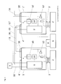
- the picture Fig.1 shows a first exemplary embodiment with two electrical controls 1 and 1 'and with a higher-level electrical control unit. 5
- the electrical controls generate regulated electrical currents for the electromagnets 2 and 2 'and are each provided with a programmable electronic control unit 9, with a connection 3 for connecting the control to the electromagnet 2, a first connector 4 for connecting the control to a higher-level electrical control unit 5, equipped with an electric current control unit 14 and with the necessary connecting lines for supplying an electromagnet.
- the second connector 20 has a contact connected to a current measuring device 12 included in the electrical drive for the line 11, which conducts an outgoing analog voltage signal which is proportional to the output to the electromagnet 2 electrical current, and another contact for the line 13, which conducts an input signal, which is present in the electrical control electronic Switch 10 is applied and thus switches off the electric current for the electromagnet.
- an electrical drive to the higher-level electrical control unit 5 is connected by a multi-core cable and with the other control with the multi-core cable 16.
- the signals from the higher-level control unit 5 for control 1 are forwarded in the mode of a digital bus via the cable 16 to the second control 1 '.
- the higher-level electrical control unit 5 participates in the fault monitoring by monitoring the device 6 actuated by the electromagnets 2 and 2 'by means of the sensor 8.
- the signal of the sensor is transmitted to one of the electrical controls 1 or 1 'and from there via the digital bus 16 to the higher-level control unit 5.
- the power supply of the magnets 2 and 2 ' is interrupted.
- the interruption is made by the electronic switches 10 and 10 'are opened by a switching signal on the line 13, wherein the switching signal on this line is generated by the superordinated control unit 5 or by one of the programmable logic controllers 9 or 9 '.
- the primary output signal of the drive 1 is the level of the regulated electrical current.
- the electric current is converted into a force in the associated electromagnet.
- a secondary output signal is a dither signal of predetermined frequency and amplitude superimposed on the regulated current.
- the picture Fig. 2 shows an alternative exemplary embodiment with two controls 1 and 1 'without a higher-level electrical control unit
- the electrical control generate regulated currents for the electromagnets 2 and 2' and are connected to a programmable logic controller 9, with a connection 3 for connection of the control to an electromagnet 2, a first connector 4 for connecting the control to an electromechanical signal generator 7, equipped with an electric current control unit 14 and with the necessary connection lines for supplying an electromagnet.
- the second connector 20 has a contact connected to a current measuring device 12 included in the electrical drive for the line 11, which conducts an outgoing analog voltage signal which is proportional to the output to the electromagnet 2 electric current, and another contact for the line 13, which conducts an input signal, which acts on a present in the electrical control electronic switch 10 and thus the electric current for the electromagnet on or off.
- Each control converts the signal received by the signal generator 7 into an electrical current for the electromagnet 2 or 2 'and compares the signal received via the line 11 or 11' from the other control with respect to the current regulated there to that from the signal from the signal generator 7 determined setpoint. If an error occurs in this comparison, the electrical activation via the line 13 and the switch 10 or 10 'switches off the currents of the electrical activations.
- the primary output of the drive is the magnitude of the regulated electrical current.
- the electric current is converted into a force in the associated electromagnet.
- the picture Fig. 3 shows a further alternative embodiment with a higher-level electrical control unit 5 and only one electrical drive. 1
- the electrical control generates a regulated electric current for the electromagnet 2 and is provided with a programmable electronic control unit 9, with a first connection 3 for connecting the control to an electromagnet 2, a first connector 4 for connecting the control to a higher-level electrical Control unit 5, equipped with an electrical control unit 14 and with the necessary connecting lines for supplying an electromagnet.
- the second connector 20 has a connected to a current measuring device 12 contained in the electrical control contact for the line 11 which conducts an outgoing analog voltage signal which is proportional to the output to the electromagnet 2 electric current.
- the connector 20 has a further contact for the line 13, which conducts an input signal which acts on an electronic switch 10 present in the electrical control and thus switches the electrical current for the electromagnet on or off.
- the electric drive 1 is connected to the higher-level electrical control unit 5 via a digital electric bus, via the line 11 for the analog signal and via the line 13 for the switching function.
- the higher-level electrical control unit predefines the desired value of the current to the electromagnet via the digital bus and checks the implementation of the specification by means of the analog signal on the line 11. In the event of an error detected in the current regulation, the higher-level control unit switches off the current of the electrical control via the electronic switch 10 by means of a switching signal on the line 13.
- the output signal of the control consists of a temporally variable regulated current profile.
- the time course is defined by the switching times related to the start and the assigned current values.
- the higher-level electrical control unit 5 sets different switching times and current values via the digital bus and triggers them to the application as needed.
- the switching times and the associated current values are stored in the electronic control unit 9.
Landscapes
- Engineering & Computer Science (AREA)
- Electromagnetism (AREA)
- Physics & Mathematics (AREA)
- General Engineering & Computer Science (AREA)
- Chemical & Material Sciences (AREA)
- Combustion & Propulsion (AREA)
- Mechanical Engineering (AREA)
- Power Engineering (AREA)
- Testing Of Short-Circuits, Discontinuities, Leakage, Or Incorrect Line Connections (AREA)
- Control Of Electric Motors In General (AREA)
- Control Of Linear Motors (AREA)
- Relay Circuits (AREA)
- Remote Monitoring And Control Of Power-Distribution Networks (AREA)
Applications Claiming Priority (1)
| Application Number | Priority Date | Filing Date | Title |
|---|---|---|---|
| DE102011122363.4A DE102011122363B4 (de) | 2011-12-23 | 2011-12-23 | Elektrische Ansteuerung für Elektromagnete |
Publications (3)
| Publication Number | Publication Date |
|---|---|
| EP2624263A2 true EP2624263A2 (fr) | 2013-08-07 |
| EP2624263A3 EP2624263A3 (fr) | 2017-08-30 |
| EP2624263B1 EP2624263B1 (fr) | 2018-10-17 |
Family
ID=47665784
Family Applications (1)
| Application Number | Title | Priority Date | Filing Date |
|---|---|---|---|
| EP12008466.0A Active EP2624263B1 (fr) | 2011-12-23 | 2012-12-20 | Commande électrique pour électroaimants |
Country Status (2)
| Country | Link |
|---|---|
| EP (1) | EP2624263B1 (fr) |
| DE (1) | DE102011122363B4 (fr) |
Families Citing this family (2)
| Publication number | Priority date | Publication date | Assignee | Title |
|---|---|---|---|---|
| DE102013005478B3 (de) * | 2013-03-28 | 2014-01-30 | Thomas Magnete Gmbh | Druckregelventil mit elektrischer Ansteuerung |
| DE102017011453B4 (de) | 2017-12-12 | 2024-10-24 | Thomas Magnete Gmbh | Elektromagnetische Vorrichtung zur gesteuerten Krafterzeugung und Verfahren zum Betrieb der Vorrichtung |
Citations (6)
| Publication number | Priority date | Publication date | Assignee | Title |
|---|---|---|---|---|
| DE10107711A1 (de) | 2000-02-23 | 2001-08-30 | Denso Corp | Elektronische Steuereinheit mit einer Verbindung zwischen zwei Leiterplatten |
| US20020037828A1 (en) | 1997-10-28 | 2002-03-28 | Wilson Leland F. | Administration of phosphodiesterase inhibitors for the treatment of premature ejaculation |
| DE102005006975A1 (de) | 2005-02-16 | 2006-08-24 | Knorr-Bremse Systeme für Nutzfahrzeuge GmbH | Mechatronische Baugruppe |
| DE102007019619A1 (de) | 2007-04-24 | 2008-11-06 | Thomas Magnete Gmbh | Elektromagnetisches Betätigungselement |
| DE102009020643A1 (de) | 2009-05-09 | 2010-11-11 | Robert Bosch Gmbh | Ventilanordnung mit integrierter Sicherheitsfunktion |
| DE102009029764A1 (de) | 2009-06-18 | 2010-12-23 | Robert Bosch Gmbh | Proportionalverstärker-Steckereinheit zur Versorgung von magnetbetätigten Hydraulikventilen und Zuleitungskabel |
Family Cites Families (7)
| Publication number | Priority date | Publication date | Assignee | Title |
|---|---|---|---|---|
| JPH01169159A (ja) * | 1987-12-25 | 1989-07-04 | Aisin Aw Co Ltd | 自動変速機の電子制御装置 |
| DE4140586C2 (de) * | 1991-12-10 | 1995-12-21 | Clark Equipment Co N D Ges D S | Verfahren und Steuereinrichtung zur Steuerung des Stroms durch eine Magnetspule |
| US5796221A (en) | 1994-07-14 | 1998-08-18 | Paper Converting Machine Company | Overload detector for servo driven machines |
| DE102006023324A1 (de) | 2006-05-11 | 2007-11-15 | Siemens Ag | Erfassung und Begrenzung maximaler Statorströme |
| DE502006003398D1 (de) * | 2006-12-20 | 2009-05-20 | Sick Ag | Modulare Sicherheitsschaltvorrichtung und Sicherheitsschaltverfahren |
| JP2010080869A (ja) * | 2008-09-29 | 2010-04-08 | Toyota Motor Corp | リニアソレノイド弁駆動回路の異常検出装置および異常検出方法 |
| US8649150B2 (en) * | 2010-11-01 | 2014-02-11 | Videojet Technologies Inc. | Solenoid protection circuit |
-
2011
- 2011-12-23 DE DE102011122363.4A patent/DE102011122363B4/de not_active Expired - Fee Related
-
2012
- 2012-12-20 EP EP12008466.0A patent/EP2624263B1/fr active Active
Patent Citations (6)
| Publication number | Priority date | Publication date | Assignee | Title |
|---|---|---|---|---|
| US20020037828A1 (en) | 1997-10-28 | 2002-03-28 | Wilson Leland F. | Administration of phosphodiesterase inhibitors for the treatment of premature ejaculation |
| DE10107711A1 (de) | 2000-02-23 | 2001-08-30 | Denso Corp | Elektronische Steuereinheit mit einer Verbindung zwischen zwei Leiterplatten |
| DE102005006975A1 (de) | 2005-02-16 | 2006-08-24 | Knorr-Bremse Systeme für Nutzfahrzeuge GmbH | Mechatronische Baugruppe |
| DE102007019619A1 (de) | 2007-04-24 | 2008-11-06 | Thomas Magnete Gmbh | Elektromagnetisches Betätigungselement |
| DE102009020643A1 (de) | 2009-05-09 | 2010-11-11 | Robert Bosch Gmbh | Ventilanordnung mit integrierter Sicherheitsfunktion |
| DE102009029764A1 (de) | 2009-06-18 | 2010-12-23 | Robert Bosch Gmbh | Proportionalverstärker-Steckereinheit zur Versorgung von magnetbetätigten Hydraulikventilen und Zuleitungskabel |
Also Published As
| Publication number | Publication date |
|---|---|
| DE102011122363A1 (de) | 2013-06-27 |
| EP2624263B1 (fr) | 2018-10-17 |
| DE102011122363B4 (de) | 2019-03-21 |
| EP2624263A3 (fr) | 2017-08-30 |
Similar Documents
| Publication | Publication Date | Title |
|---|---|---|
| EP2017869A2 (fr) | Dispositif de sécurité destiné à la commande à plusieurs canaux d'un dispositif de sécurité | |
| EP2728314B1 (fr) | Agencement de mesure pour la détermination d'une grandeur de mesure | |
| DE202012101654U1 (de) | Kompaktsteuergerät zum fehlersicheren Ansteuern eines elektrischen Aktors | |
| EP1834220B1 (fr) | Dispositif de soupape electrohydraulique redondant | |
| WO2011100949A1 (fr) | Circuit de sécurité passif | |
| EP2624263B1 (fr) | Commande électrique pour électroaimants | |
| EP2304256A1 (fr) | Système d'actionneurs | |
| EP2433184B1 (fr) | Système de commande permettant de commander un processus | |
| EP2154587A2 (fr) | Système de positionnement d'un actionneur | |
| WO2013110296A1 (fr) | Dispositif d'alimentation, de commande et/ou d'évaluation à sécurité intrinsèque d'appareils de terrain dans la zone protégée des explosions | |
| EP3774628A1 (fr) | Système d'ascenseur | |
| DE10261454B4 (de) | Motorsteuerung mit sicherem Halt | |
| DE102010038459A1 (de) | Sicherheitssystem | |
| EP1990785B1 (fr) | Surveillance de paramétrage pour composants de signal analogique | |
| WO2004059812A1 (fr) | Commande moteur comportant un dispositif de commande et un dispositif de securite destine a couper le moteur de façon sure | |
| DE102010021640A1 (de) | Verfahren und Vorrichtung zur Ansteuerung einer Armatur | |
| WO2005064622A1 (fr) | Montage electrique pour commander une soupape fluidique a actionnement magnetique | |
| WO2004059829A1 (fr) | Moteur electrique a dispositif de commande electronique integre | |
| DE102020122147B4 (de) | Elektrohydraulische steuereinheit mit notbetrieb und umschalt- und diagnoseeinheit für ausfallsicheren betrieb | |
| EP2820738B1 (fr) | Dispositif d'entrée/sortie multifonction | |
| EP1692578A1 (fr) | Unite peripherique d'un systeme de commande redondant | |
| DE102012012047A1 (de) | Antriebsregler und Verfahren zur Stillsetzung einer Achse | |
| DE10261453B4 (de) | Motorsteuerung | |
| DE102024113022A1 (de) | Antriebssystem für einen Aktuator | |
| DE102024125163A1 (de) | System zum Betrieb eines Aktors |
Legal Events
| Date | Code | Title | Description |
|---|---|---|---|
| PUAI | Public reference made under article 153(3) epc to a published international application that has entered the european phase |
Free format text: ORIGINAL CODE: 0009012 |
|
| AK | Designated contracting states |
Kind code of ref document: A2 Designated state(s): AL AT BE BG CH CY CZ DE DK EE ES FI FR GB GR HR HU IE IS IT LI LT LU LV MC MK MT NL NO PL PT RO RS SE SI SK SM TR |
|
| AX | Request for extension of the european patent |
Extension state: BA ME |
|
| PUAL | Search report despatched |
Free format text: ORIGINAL CODE: 0009013 |
|
| AK | Designated contracting states |
Kind code of ref document: A3 Designated state(s): AL AT BE BG CH CY CZ DE DK EE ES FI FR GB GR HR HU IE IS IT LI LT LU LV MC MK MT NL NO PL PT RO RS SE SI SK SM TR |
|
| AX | Request for extension of the european patent |
Extension state: BA ME |
|
| RIC1 | Information provided on ipc code assigned before grant |
Ipc: H01F 7/18 20060101AFI20170725BHEP Ipc: H01H 47/32 20060101ALI20170725BHEP Ipc: F02D 41/20 20060101ALI20170725BHEP |
|
| RAP1 | Party data changed (applicant data changed or rights of an application transferred) |
Owner name: THOMAS MAGNETE GMBH |
|
| STAA | Information on the status of an ep patent application or granted ep patent |
Free format text: STATUS: REQUEST FOR EXAMINATION WAS MADE |
|
| 17P | Request for examination filed |
Effective date: 20180219 |
|
| GRAP | Despatch of communication of intention to grant a patent |
Free format text: ORIGINAL CODE: EPIDOSNIGR1 |
|
| STAA | Information on the status of an ep patent application or granted ep patent |
Free format text: STATUS: GRANT OF PATENT IS INTENDED |
|
| RIC1 | Information provided on ipc code assigned before grant |
Ipc: F02D 41/22 20060101ALI20180625BHEP Ipc: F02D 41/20 20060101ALI20180625BHEP Ipc: H01H 47/32 20060101ALI20180625BHEP Ipc: H01F 7/18 20060101AFI20180625BHEP |
|
| INTG | Intention to grant announced |
Effective date: 20180723 |
|
| GRAS | Grant fee paid |
Free format text: ORIGINAL CODE: EPIDOSNIGR3 |
|
| GRAA | (expected) grant |
Free format text: ORIGINAL CODE: 0009210 |
|
| STAA | Information on the status of an ep patent application or granted ep patent |
Free format text: STATUS: THE PATENT HAS BEEN GRANTED |
|
| AK | Designated contracting states |
Kind code of ref document: B1 Designated state(s): AL AT BE BG CH CY CZ DE DK EE ES FI FR GB GR HR HU IE IS IT LI LT LU LV MC MK MT NL NO PL PT RO RS SE SI SK SM TR |
|
| REG | Reference to a national code |
Ref country code: GB Ref legal event code: FG4D Free format text: NOT ENGLISH |
|
| REG | Reference to a national code |
Ref country code: CH Ref legal event code: EP |
|
| REG | Reference to a national code |
Ref country code: IE Ref legal event code: FG4D Free format text: LANGUAGE OF EP DOCUMENT: GERMAN |
|
| REG | Reference to a national code |
Ref country code: DE Ref legal event code: R096 Ref document number: 502012013618 Country of ref document: DE Ref country code: AT Ref legal event code: REF Ref document number: 1054945 Country of ref document: AT Kind code of ref document: T Effective date: 20181115 |
|
| REG | Reference to a national code |
Ref country code: NL Ref legal event code: MP Effective date: 20181017 |
|
| REG | Reference to a national code |
Ref country code: LT Ref legal event code: MG4D |
|
| PG25 | Lapsed in a contracting state [announced via postgrant information from national office to epo] |
Ref country code: NL Free format text: LAPSE BECAUSE OF FAILURE TO SUBMIT A TRANSLATION OF THE DESCRIPTION OR TO PAY THE FEE WITHIN THE PRESCRIBED TIME-LIMIT Effective date: 20181017 |
|
| PG25 | Lapsed in a contracting state [announced via postgrant information from national office to epo] |
Ref country code: NO Free format text: LAPSE BECAUSE OF FAILURE TO SUBMIT A TRANSLATION OF THE DESCRIPTION OR TO PAY THE FEE WITHIN THE PRESCRIBED TIME-LIMIT Effective date: 20190117 Ref country code: LV Free format text: LAPSE BECAUSE OF FAILURE TO SUBMIT A TRANSLATION OF THE DESCRIPTION OR TO PAY THE FEE WITHIN THE PRESCRIBED TIME-LIMIT Effective date: 20181017 Ref country code: FI Free format text: LAPSE BECAUSE OF FAILURE TO SUBMIT A TRANSLATION OF THE DESCRIPTION OR TO PAY THE FEE WITHIN THE PRESCRIBED TIME-LIMIT Effective date: 20181017 Ref country code: IS Free format text: LAPSE BECAUSE OF FAILURE TO SUBMIT A TRANSLATION OF THE DESCRIPTION OR TO PAY THE FEE WITHIN THE PRESCRIBED TIME-LIMIT Effective date: 20190217 Ref country code: BG Free format text: LAPSE BECAUSE OF FAILURE TO SUBMIT A TRANSLATION OF THE DESCRIPTION OR TO PAY THE FEE WITHIN THE PRESCRIBED TIME-LIMIT Effective date: 20190117 Ref country code: ES Free format text: LAPSE BECAUSE OF FAILURE TO SUBMIT A TRANSLATION OF THE DESCRIPTION OR TO PAY THE FEE WITHIN THE PRESCRIBED TIME-LIMIT Effective date: 20181017 Ref country code: LT Free format text: LAPSE BECAUSE OF FAILURE TO SUBMIT A TRANSLATION OF THE DESCRIPTION OR TO PAY THE FEE WITHIN THE PRESCRIBED TIME-LIMIT Effective date: 20181017 Ref country code: HR Free format text: LAPSE BECAUSE OF FAILURE TO SUBMIT A TRANSLATION OF THE DESCRIPTION OR TO PAY THE FEE WITHIN THE PRESCRIBED TIME-LIMIT Effective date: 20181017 Ref country code: PL Free format text: LAPSE BECAUSE OF FAILURE TO SUBMIT A TRANSLATION OF THE DESCRIPTION OR TO PAY THE FEE WITHIN THE PRESCRIBED TIME-LIMIT Effective date: 20181017 |
|
| PG25 | Lapsed in a contracting state [announced via postgrant information from national office to epo] |
Ref country code: GR Free format text: LAPSE BECAUSE OF FAILURE TO SUBMIT A TRANSLATION OF THE DESCRIPTION OR TO PAY THE FEE WITHIN THE PRESCRIBED TIME-LIMIT Effective date: 20190118 Ref country code: AL Free format text: LAPSE BECAUSE OF FAILURE TO SUBMIT A TRANSLATION OF THE DESCRIPTION OR TO PAY THE FEE WITHIN THE PRESCRIBED TIME-LIMIT Effective date: 20181017 Ref country code: PT Free format text: LAPSE BECAUSE OF FAILURE TO SUBMIT A TRANSLATION OF THE DESCRIPTION OR TO PAY THE FEE WITHIN THE PRESCRIBED TIME-LIMIT Effective date: 20190217 Ref country code: SE Free format text: LAPSE BECAUSE OF FAILURE TO SUBMIT A TRANSLATION OF THE DESCRIPTION OR TO PAY THE FEE WITHIN THE PRESCRIBED TIME-LIMIT Effective date: 20181017 Ref country code: RS Free format text: LAPSE BECAUSE OF FAILURE TO SUBMIT A TRANSLATION OF THE DESCRIPTION OR TO PAY THE FEE WITHIN THE PRESCRIBED TIME-LIMIT Effective date: 20181017 |
|
| REG | Reference to a national code |
Ref country code: DE Ref legal event code: R097 Ref document number: 502012013618 Country of ref document: DE |
|
| PG25 | Lapsed in a contracting state [announced via postgrant information from national office to epo] |
Ref country code: DK Free format text: LAPSE BECAUSE OF FAILURE TO SUBMIT A TRANSLATION OF THE DESCRIPTION OR TO PAY THE FEE WITHIN THE PRESCRIBED TIME-LIMIT Effective date: 20181017 Ref country code: CZ Free format text: LAPSE BECAUSE OF FAILURE TO SUBMIT A TRANSLATION OF THE DESCRIPTION OR TO PAY THE FEE WITHIN THE PRESCRIBED TIME-LIMIT Effective date: 20181017 |
|
| REG | Reference to a national code |
Ref country code: CH Ref legal event code: PL |
|
| PLBE | No opposition filed within time limit |
Free format text: ORIGINAL CODE: 0009261 |
|
| STAA | Information on the status of an ep patent application or granted ep patent |
Free format text: STATUS: NO OPPOSITION FILED WITHIN TIME LIMIT |
|
| PG25 | Lapsed in a contracting state [announced via postgrant information from national office to epo] |
Ref country code: RO Free format text: LAPSE BECAUSE OF FAILURE TO SUBMIT A TRANSLATION OF THE DESCRIPTION OR TO PAY THE FEE WITHIN THE PRESCRIBED TIME-LIMIT Effective date: 20181017 Ref country code: SM Free format text: LAPSE BECAUSE OF FAILURE TO SUBMIT A TRANSLATION OF THE DESCRIPTION OR TO PAY THE FEE WITHIN THE PRESCRIBED TIME-LIMIT Effective date: 20181017 Ref country code: EE Free format text: LAPSE BECAUSE OF FAILURE TO SUBMIT A TRANSLATION OF THE DESCRIPTION OR TO PAY THE FEE WITHIN THE PRESCRIBED TIME-LIMIT Effective date: 20181017 Ref country code: MC Free format text: LAPSE BECAUSE OF FAILURE TO SUBMIT A TRANSLATION OF THE DESCRIPTION OR TO PAY THE FEE WITHIN THE PRESCRIBED TIME-LIMIT Effective date: 20181017 Ref country code: SK Free format text: LAPSE BECAUSE OF FAILURE TO SUBMIT A TRANSLATION OF THE DESCRIPTION OR TO PAY THE FEE WITHIN THE PRESCRIBED TIME-LIMIT Effective date: 20181017 Ref country code: LU Free format text: LAPSE BECAUSE OF NON-PAYMENT OF DUE FEES Effective date: 20181220 |
|
| REG | Reference to a national code |
Ref country code: IE Ref legal event code: MM4A |
|
| 26N | No opposition filed |
Effective date: 20190718 |
|
| GBPC | Gb: european patent ceased through non-payment of renewal fee |
Effective date: 20190117 |
|
| REG | Reference to a national code |
Ref country code: BE Ref legal event code: MM Effective date: 20181231 |
|
| REG | Reference to a national code |
Ref country code: SE Ref legal event code: TRGR Ref country code: SE Ref legal event code: RINS Effective date: 20190927 |
|
| PG25 | Lapsed in a contracting state [announced via postgrant information from national office to epo] |
Ref country code: SI Free format text: LAPSE BECAUSE OF FAILURE TO SUBMIT A TRANSLATION OF THE DESCRIPTION OR TO PAY THE FEE WITHIN THE PRESCRIBED TIME-LIMIT Effective date: 20181017 Ref country code: IE Free format text: LAPSE BECAUSE OF NON-PAYMENT OF DUE FEES Effective date: 20181220 Ref country code: FR Free format text: LAPSE BECAUSE OF NON-PAYMENT OF DUE FEES Effective date: 20181231 |
|
| PG25 | Lapsed in a contracting state [announced via postgrant information from national office to epo] |
Ref country code: BE Free format text: LAPSE BECAUSE OF NON-PAYMENT OF DUE FEES Effective date: 20181231 |
|
| PG25 | Lapsed in a contracting state [announced via postgrant information from national office to epo] |
Ref country code: LI Free format text: LAPSE BECAUSE OF NON-PAYMENT OF DUE FEES Effective date: 20181231 Ref country code: CH Free format text: LAPSE BECAUSE OF NON-PAYMENT OF DUE FEES Effective date: 20181231 Ref country code: GB Free format text: LAPSE BECAUSE OF NON-PAYMENT OF DUE FEES Effective date: 20190117 |
|
| PG25 | Lapsed in a contracting state [announced via postgrant information from national office to epo] |
Ref country code: MT Free format text: LAPSE BECAUSE OF FAILURE TO SUBMIT A TRANSLATION OF THE DESCRIPTION OR TO PAY THE FEE WITHIN THE PRESCRIBED TIME-LIMIT Effective date: 20181017 |
|
| REG | Reference to a national code |
Ref country code: AT Ref legal event code: MM01 Ref document number: 1054945 Country of ref document: AT Kind code of ref document: T Effective date: 20181220 |
|
| PG25 | Lapsed in a contracting state [announced via postgrant information from national office to epo] |
Ref country code: TR Free format text: LAPSE BECAUSE OF FAILURE TO SUBMIT A TRANSLATION OF THE DESCRIPTION OR TO PAY THE FEE WITHIN THE PRESCRIBED TIME-LIMIT Effective date: 20181017 |
|
| PG25 | Lapsed in a contracting state [announced via postgrant information from national office to epo] |
Ref country code: AT Free format text: LAPSE BECAUSE OF NON-PAYMENT OF DUE FEES Effective date: 20181220 |
|
| PG25 | Lapsed in a contracting state [announced via postgrant information from national office to epo] |
Ref country code: MK Free format text: LAPSE BECAUSE OF NON-PAYMENT OF DUE FEES Effective date: 20181017 Ref country code: HU Free format text: LAPSE BECAUSE OF FAILURE TO SUBMIT A TRANSLATION OF THE DESCRIPTION OR TO PAY THE FEE WITHIN THE PRESCRIBED TIME-LIMIT; INVALID AB INITIO Effective date: 20121220 Ref country code: CY Free format text: LAPSE BECAUSE OF FAILURE TO SUBMIT A TRANSLATION OF THE DESCRIPTION OR TO PAY THE FEE WITHIN THE PRESCRIBED TIME-LIMIT Effective date: 20181017 |
|
| PG25 | Lapsed in a contracting state [announced via postgrant information from national office to epo] |
Ref country code: SE Free format text: LAPSE BECAUSE OF FAILURE TO SUBMIT A TRANSLATION OF THE DESCRIPTION OR TO PAY THE FEE WITHIN THE PRESCRIBED TIME-LIMIT Effective date: 20181017 |
|
| PGRI | Patent reinstated in contracting state [announced from national office to epo] |
Ref country code: SE Effective date: 20190927 |
|
| PGFP | Annual fee paid to national office [announced via postgrant information from national office to epo] |
Ref country code: SE Payment date: 20251217 Year of fee payment: 14 |
|
| PGFP | Annual fee paid to national office [announced via postgrant information from national office to epo] |
Ref country code: DE Payment date: 20251231 Year of fee payment: 14 |
|
| REG | Reference to a national code |
Ref country code: DE Ref legal event code: R081 Ref document number: 502012013618 Country of ref document: DE Owner name: THOMAS GMBH, DE Free format text: FORMER OWNER: THOMAS MAGNETE GMBH, 57562 HERDORF, DE |
|
| PGFP | Annual fee paid to national office [announced via postgrant information from national office to epo] |
Ref country code: IT Payment date: 20251231 Year of fee payment: 14 |