EP2624367B1 - Structure de connexion de borne - Google Patents
Structure de connexion de borne Download PDFInfo
- Publication number
- EP2624367B1 EP2624367B1 EP11829313.3A EP11829313A EP2624367B1 EP 2624367 B1 EP2624367 B1 EP 2624367B1 EP 11829313 A EP11829313 A EP 11829313A EP 2624367 B1 EP2624367 B1 EP 2624367B1
- Authority
- EP
- European Patent Office
- Prior art keywords
- terminal
- section
- pair
- holder
- connection structure
- Prior art date
- Legal status (The legal status is an assumption and is not a legal conclusion. Google has not performed a legal analysis and makes no representation as to the accuracy of the status listed.)
- Active
Links
- 230000008878 coupling Effects 0.000 claims description 22
- 238000010168 coupling process Methods 0.000 claims description 22
- 238000005859 coupling reaction Methods 0.000 claims description 22
- 238000005192 partition Methods 0.000 description 18
- 230000002265 prevention Effects 0.000 description 14
- 229920003002 synthetic resin Polymers 0.000 description 4
- 239000000057 synthetic resin Substances 0.000 description 4
- 239000002184 metal Substances 0.000 description 3
- 239000004020 conductor Substances 0.000 description 1
- 230000000694 effects Effects 0.000 description 1
- 230000004048 modification Effects 0.000 description 1
- 238000012986 modification Methods 0.000 description 1
- 230000000149 penetrating effect Effects 0.000 description 1
Images


Classifications
-
- H—ELECTRICITY
- H01—ELECTRIC ELEMENTS
- H01R—ELECTRICALLY-CONDUCTIVE CONNECTIONS; STRUCTURAL ASSOCIATIONS OF A PLURALITY OF MUTUALLY-INSULATED ELECTRICAL CONNECTING ELEMENTS; COUPLING DEVICES; CURRENT COLLECTORS
- H01R13/00—Details of coupling devices of the kinds covered by groups H01R12/70 or H01R24/00 - H01R33/00
- H01R13/46—Bases; Cases
- H01R13/516—Means for holding or embracing insulating body, e.g. casing, hoods
-
- H—ELECTRICITY
- H01—ELECTRIC ELEMENTS
- H01R—ELECTRICALLY-CONDUCTIVE CONNECTIONS; STRUCTURAL ASSOCIATIONS OF A PLURALITY OF MUTUALLY-INSULATED ELECTRICAL CONNECTING ELEMENTS; COUPLING DEVICES; CURRENT COLLECTORS
- H01R13/00—Details of coupling devices of the kinds covered by groups H01R12/70 or H01R24/00 - H01R33/00
- H01R13/62—Means for facilitating engagement or disengagement of coupling parts or for holding them in engagement
- H01R13/629—Additional means for facilitating engagement or disengagement of coupling parts, e.g. aligning or guiding means, levers, gas pressure electrical locking indicators, manufacturing tolerances
- H01R13/631—Additional means for facilitating engagement or disengagement of coupling parts, e.g. aligning or guiding means, levers, gas pressure electrical locking indicators, manufacturing tolerances for engagement only
- H01R13/6315—Additional means for facilitating engagement or disengagement of coupling parts, e.g. aligning or guiding means, levers, gas pressure electrical locking indicators, manufacturing tolerances for engagement only allowing relative movement between coupling parts, e.g. floating connection
-
- H—ELECTRICITY
- H01—ELECTRIC ELEMENTS
- H01R—ELECTRICALLY-CONDUCTIVE CONNECTIONS; STRUCTURAL ASSOCIATIONS OF A PLURALITY OF MUTUALLY-INSULATED ELECTRICAL CONNECTING ELEMENTS; COUPLING DEVICES; CURRENT COLLECTORS
- H01R13/00—Details of coupling devices of the kinds covered by groups H01R12/70 or H01R24/00 - H01R33/00
- H01R13/02—Contact members
- H01R13/193—Means for increasing contact pressure at the end of engagement of coupling part, e.g. zero insertion force or no friction
-
- H—ELECTRICITY
- H01—ELECTRIC ELEMENTS
- H01R—ELECTRICALLY-CONDUCTIVE CONNECTIONS; STRUCTURAL ASSOCIATIONS OF A PLURALITY OF MUTUALLY-INSULATED ELECTRICAL CONNECTING ELEMENTS; COUPLING DEVICES; CURRENT COLLECTORS
- H01R2105/00—Three poles
-
- H—ELECTRICITY
- H01—ELECTRIC ELEMENTS
- H01R—ELECTRICALLY-CONDUCTIVE CONNECTIONS; STRUCTURAL ASSOCIATIONS OF A PLURALITY OF MUTUALLY-INSULATED ELECTRICAL CONNECTING ELEMENTS; COUPLING DEVICES; CURRENT COLLECTORS
- H01R2201/00—Connectors or connections adapted for particular applications
- H01R2201/26—Connectors or connections adapted for particular applications for vehicles
-
- H—ELECTRICITY
- H01—ELECTRIC ELEMENTS
- H01R—ELECTRICALLY-CONDUCTIVE CONNECTIONS; STRUCTURAL ASSOCIATIONS OF A PLURALITY OF MUTUALLY-INSULATED ELECTRICAL CONNECTING ELEMENTS; COUPLING DEVICES; CURRENT COLLECTORS
- H01R25/00—Coupling parts adapted for simultaneous co-operation with two or more identical counterparts, e.g. for distributing energy to two or more circuits
- H01R25/14—Rails or bus-bars constructed so that the counterparts can be connected thereto at any point along their length
-
- H—ELECTRICITY
- H01—ELECTRIC ELEMENTS
- H01R—ELECTRICALLY-CONDUCTIVE CONNECTIONS; STRUCTURAL ASSOCIATIONS OF A PLURALITY OF MUTUALLY-INSULATED ELECTRICAL CONNECTING ELEMENTS; COUPLING DEVICES; CURRENT COLLECTORS
- H01R4/00—Electrically-conductive connections between two or more conductive members in direct contact, i.e. touching one another; Means for effecting or maintaining such contact; Electrically-conductive connections having two or more spaced connecting locations for conductors and using contact members penetrating insulation
- H01R4/28—Clamped connections, spring connections
- H01R4/48—Clamped connections, spring connections utilising a spring, clip, or other resilient member
-
- Y—GENERAL TAGGING OF NEW TECHNOLOGICAL DEVELOPMENTS; GENERAL TAGGING OF CROSS-SECTIONAL TECHNOLOGIES SPANNING OVER SEVERAL SECTIONS OF THE IPC; TECHNICAL SUBJECTS COVERED BY FORMER USPC CROSS-REFERENCE ART COLLECTIONS [XRACs] AND DIGESTS
- Y02—TECHNOLOGIES OR APPLICATIONS FOR MITIGATION OR ADAPTATION AGAINST CLIMATE CHANGE
- Y02E—REDUCTION OF GREENHOUSE GAS [GHG] EMISSIONS, RELATED TO ENERGY GENERATION, TRANSMISSION OR DISTRIBUTION
- Y02E60/00—Enabling technologies; Technologies with a potential or indirect contribution to GHG emissions mitigation
- Y02E60/10—Energy storage using batteries
Definitions
- This invention relates to a terminal connection structure for connecting terminal fixtures to each other, in particular, the terminal connection structure for connecting to a power device to which voltage for running a vehicle is applied.
- a power device such as a battery, an inverter, a motor, a generator, and the like to which voltage for running a vehicle is applied is mounted on a vehicle driven by a rotary drive power of a motor such as a hybrid vehicle and an electric vehicle. Because a value of an electric current flowing through these power devices is high, cables used for connecting the power devices to each other are thicker than electric wires used for transmitting a signal and supplying electric power to electronic devices. Further, conventionally, various terminal connection structures (for example, see PTL 1) are used for connecting these thick cables to the power devices.
- the terminal connection structure described in the PTL 1 includes: a male connector; and a female connector configured to be connected to each other.
- the male connector includes: a male connector housing; and male terminal fixtures respectively connected to coils of a motor as the power device and received in the male connector housing.
- the male connector housing includes: an outer tubular section as a base; an inner tubular section received in the outer tubular section and fitted to a female connector housing; and a thin flexible coupling piece continued to the outer and inner tubular sections.
- the female connector includes: a female connector housing; and female terminal fixtures received in the female connector housing and configured to be connected to the male terminal fixtures.
- the terminal connection structure described in the PTL 1 allows the terminal fixtures to be connected to each other by elastically deforming the thin coupling piece even if a position of the male connector, namely, the male terminal fixture connected to the coil of the motor is offset upon fitting the female connector to the male connector.
- PTL 2 describes a self aligning connection system for wires.
- PTL 3 describes a semi- permanent connection for a bus bar.
- PTL 4 discloses a conducting strip for connecting bus bars.
- PTL 5 describes a connector fixing structure to fix the conductor to a base part.
- the outer and inner tubular sections of the male connector housing are coupled to each other by the thin coupling piece, and the terminal fixtures are connected to each other by elastically deforming the thin coupling piece.
- the elastically deformed thin coupling piece may prevent the inner tubular section from moving.
- the terminal connection structure described in the PTL 1 only supports a small positional offset of the terminal fixtures.
- an object of the present invention is to provide a terminal connection structure that can reliably connect terminal fixtures together even if the positional offset of the terminal fixtures is great.
- a terminal connection structure for connecting a second terminal fixture to a first terminal fixture which is connected to a power device, said terminal connection structure comprising:
- the terminal connection structure as described in the first aspect further including: a clip terminal having a pair of contact pieces for holding the first and second terminal fixtures in the overlapping state therebetween, and a bias coupling section continued to the pair of contact pieces and biasing the pair of contact pieces holding the first and second terminal fixtures therebetween toward a direction close to each other, said clip terminal configured to be moved close to the terminal holder in a direction crossing the first and second terminal fixtures in the overlapping state, and attached to the terminal holder with the pair of contact pieces holding the first and second terminal fixtures in the overlapping state therebetween.
- the terminal connection structure as described in the second aspect further including: a clip terminal holder covering the clip terminal and having a locking section to be locked with the terminal holder.
- the terminal connection structure as described in the first aspect of the present invention when the parallel wall provided on one of the terminal holder and the base is inserted into the holding slit that is larger than the parallel wall, the terminal holder becomes movable in a direction parallel to a surface of the bottom wall of the base. Therefore, there is nothing that prevents the terminal holder from moving other than an inner wall of the holding slit.
- the terminal connection structure as described in the second aspect of the present invention when the first and second terminal fixtures are held between the pair of contact pieces of the clip terminal close to these terminal fixtures along a direction crossing a longitudinal direction of these terminal fixtures in the overlapping state, these terminal fixtures are connected to each other. Therefore, even if the first and second terminal fixtures are arranged parallel to each other with a gap, these terminal fixtures can be surely connected to each other.
- the clip terminal includes the pair of contact pieces and the bias coupling section biasing the pair of contact pieces toward a direction close to each other, the terminal fixtures in the overlapping state can be held between the pair of contact pieces. Therefore, the first and second terminal fixtures can be surely and electrically connected to each other.
- the terminal connection structure includes the clip terminal holder covering the clip terminal and locked with the terminal holder, the clip terminal holder prevents the clip terminal from falling out.
- the terminal connection structure includes the press fixing member pressing the first terminal fixture toward the bottom wall when attached to the base, the first terminal fixture can be positioned in a thickness direction of the bottom wall of the base by the press fixing member.
- the terminal holder because there is nothing that prevents the terminal holder from moving other than an inner wall of the holding slit, the terminal holder becomes movable with respect to the bottom wall of the base within a gap between the holding slit and the parallel wall. Therefore, by adjusting properly a size of the holding slit, the terminal fixtures can be moved widely with respect to the base, and even if the positional offset between the terminal fixtures is great, the terminal fixtures are surely connected to each other.
- the terminal connection structure can be downsized.
- the terminal fixtures By holding the terminal fixtures in the overlapping state between the pair of contact pieces of the clip terminal, the first and second terminal fixtures can be surely and electrically connected to each other. Therefore, the terminal fixtures can be surely connected to each other.
- the clip terminal holder prevents the clip terminal from falling out, a connection between the terminal fixtures is prevented from being released unexpectedly.
- the first terminal fixture can be positioned in a thickness direction of the bottom wall of the base by the bias fixing member.
- a terminal connection structure 1 connects a first terminal fixture 3 connected to a coil 2 of a motor as one power device with a busbar 4 as a second terminal fixture connected to an inverter as the other power device.
- the power device of the present invention means a device to which a voltage for running a vehicle is applied such as a battery, an inverter, a motor, and a generator.
- the first terminal fixture 3 is made of conductive metal. As shown in Fig. 2 , the first terminal fixture 3 integrally includes: a gutter-shaped coil connecting section 5; and a band-plate-shaped electric contact section 6.
- the coil connecting section 5 integrally includes: a bottom plate section 7; and a pair of side plate sections 8 extended vertically from both edges in a width direction of the bottom plate section 7, and is formed in a gutter shape. When the coil 2 is overlapped with the bottom plate section 7, the coil 2 is attached to the coil connecting section 5. Both surfaces of the electric contact section 6 are arranged on the same plane as both surface of one of the side plate sections 8.
- the number of the first terminal fixture 3 is six in an example shown in Figs. 1 and 2 . Further, a plurality of first terminal fixtures 3 is arranged parallel to each other with a gap. Namely, the surfaces of the electric contact sections 6 of the first terminal fixtures 3 are arranged parallel to each other with a gap.
- the busbar 4 is made of conductive metal. As shown in Fig. 2 , the busbar 4 is formed in a band plate shape and bent 90 degree at two positions, and is flexible (namely, elastically deformable). The number of the busbar 4 is six in an example shown in Figs. 1 and 2 . A thin-walled section 9 as the electric contact portion thinner than the other sections is provided on one end of the busbar 4. Further, a connector housing 10 for connecting with the inverter as the other power device is attached to the other end of the busbar 4. Further, a plurality of busbars 4 is arranged parallel to each other with a gap. Namely, surfaces of the thin-walled sections 9 of the busbars 4 are arranged parallel to each other with a gap.
- the terminal connection structure 1 respectively connects three first terminal fixtures 3 with three busbars 4. Of course, the terminal connection structure 1 connects the terminal connection structure 1 with the busbar 4 one to one. Namely, in the example shown in Figs. 1 and 2 , two terminal connection structures 1 are provided. As shown in Figs. 1 and 2 , the terminal connection structure 1 includes: a base 11; a terminal holder 12; a mobile attachment section 13; a clip connector 14; and a press fixing member 15.
- the base 11 is made of insulating synthetic resin, and as shown in Fig. 3 , integrally includes: a flat-plate-shaped bottom wall 16; a pair of vertically extended pieces 17 extended vertically from both edges of the bottom wall 16; two edge projection sections 18; two partition projection sections 19; and parallel wall sections 20.
- An engaging hole 21 penetrates the center of the vertically extended piece 17.
- the edge projection sections 18 are projected from both edges of the bottom wall 16 from which the vertically extended pieces 17 are vertically extended and arranged in the same plane as the pair of vertically extended pieces 17.
- Each partition projection section 19 is formed in a straight shape, and projected from the bottom wall 16.
- the partition projection sections 19 are arranged parallel to each other with a gap.
- the partition projection sections 19 are provided between the pair of vertically extended pieces 17.
- a longitudinal direction of the partition projection section 19 is parallel to both surfaces of the vertically extended pieces 17.
- the parallel wall sections 20 are respectively continued to tips of the edge projection sections 18 and the partition projection sections 19, and provided parallel to the bottom wall 16 with a gap. Further, the parallel wall sections 20 adjacent to each other are provided with a gap.
- the terminal holder 12 is made of insulating synthetic resin, and as shown in Fig. 4 , integrally includes: a flat-plate-shaped bottom plate section 22 as a parallel wall; a pair of vertically extended pillars 23 extended vertically from both edges of the bottom plate section 22; a pair of coupling beams 24; and a supporting piece 25.
- a width of the bottom plate section 22 is formed narrower than an interval between the edge projection section 18 and the partition projection section 19 adjacent to each other, and narrower than an interval between the partition projection sections 19.
- the bottom plate section 22 is inserted into the interval between the edge projection section 18 and the partition projection section 19 adjacent to each other, and into the interval between the partition projection sections 19. Further, the bottom plate section 22 is inserted into between the bottom wall 16 and the parallel wall section 20.
- the pair of vertically extended pillars 23 is extended vertically from both ends in a longitudinal direction of the bottom plate section 22, and provided parallel to each other with a gap.
- a through-hole 26 for passing the thin-walled section 9 provided on one end of the busbar 4 and not passing the other sections of the busbar 4 penetrates one vertically extended pillar 23 disposed at a front side of Fig. 4 .
- the other vertically extended pillar 23 at a rear side of Fig. 4 is provided with a slit 27 extended from a top end to a bottom end near the bottom plate section 22 of the vertically extended pillar 23.
- a tapered section 28 gradually reducing a width of the slit 27 as extended toward the bottom plate section 22 is provided on a top end of the other vertically extended pillar 23.
- the pair of coupling beams 24 is spaced from the bottom plate section 22. A longitudinal direction of the pair of coupling beams 24 is provided parallel to a surface of the bottom plate section 22.
- the pair of coupling beams 24 couples the pair of vertically extended pillars 23 to each other.
- the supporting piece 25 is extended from the center of the other vertically extended pillar 23 toward a direction away from the one vertically extended pillar 23.
- the supporting piece 25 supports the coil connecting section 5 of the first terminal fixture 3 by overlapping the coil connecting section 5 on a surface of the supporting piece 25.
- the terminal holder 12 is attached to the base 11. Then, the thin-walled sections 9 of the busbar 4 is passed through the through-hole 26 of the terminal holder 12, and the electric contact section 6 of the first terminal fixture 3 is received in the slit 27 of the terminal holder 12. Further, the coil connecting section 5 of the first terminal fixture 3 is overlapped with the supporting piece 25 of the terminal holder 12. Thus, the terminal holder 12 holds the thin-walled sections 9 of the busbar 4 and the electric contact section 6 of the first terminal fixture 3 in a manner that the thin-walled sections 9 and the electric contact section 6 are overlapped with each other.
- the mobile attachment section 13 includes: the bottom plate section 22; a holding slit 29; a dropout prevention hole 30; and a dropout prevention projection 31.
- the bottom plate sections 22 are inserted into the intervals between the edge projection section 18 and the partition projection section 19 adjacent to each other, between the partition projection sections 19, and between the bottom wall 16 and the parallel wall section 20, and provided parallel to the bottom wall 16.
- the holding slits 29 are spaces between the edge projection section 18 and the partition projection section 19 adjacent to each other, between the partition projection sections 19, and between the bottom wall 16 and the parallel wall section 20. Resultingly, in an example shown in Fig. 3 , the number of the holding slit 29 is three.
- the holding slit 29 is formed wider (larger) than an outer shape of the bottom plate section 22.
- the dropout prevention hole 30 is a rectangular hole in a plan view penetrating the bottom wall 16.
- the number of the dropout prevention hole 30 is the same as the terminal holder 12, namely, the holding slit 29.
- the dropout prevention hole 30 is respectively provided on the interval between the edge projection section 18 and the partition projection section 19 adjacent to each other of the bottom wall 16 and on the interval between the partition projection sections 19 one by one.
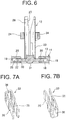
- the dropout prevention projection 31 is projected from the bottom plate section 22 of the terminal holder 12 in a direction opposite to the vertically extended pillars 23. As shown in Fig. 6 , by entering an inside of the dropout prevention hole 30, the dropout prevention projection 31 prevents the bottom plate section 22, namely, the terminal holder 12 from dropping out of the bottom wall 16, namely, the base 11.
- a planar shape of the dropout prevention projection 31 is smaller enough than a planar shape of the dropout prevention hole 30 so that the dropout prevention projection 31 does not interfere with a movement of the bottom plate section 7 in the holding slit 29, namely, the shape of the dropout prevention projection 31 is so formed as to allow the bottom plate section 22 movable throughout the holding slit 29.
- the terminal holder 12 is attached to the base 11 movable in a direction parallel to a surface of the bottom wall 16.
- the number of the clip connector 14 is the same as the terminal holder 12 and the holding slit 29 (three in an example shown in figures).
- the clip connector 14 includes: a clip terminal 33; and a clip terminal holder 34.
- the clip terminal 33 is made of conductive metal.
- the clip terminal 33 integrally includes: a pair of contact pieces 35 formed in substantially a plate shape, and arranged parallel to each other with a gap; and a bias coupling section 36 respectively continued to the contact pieces 35.
- the clip terminal 33 holds the electric contact section 6 of the first terminal fixture 3 and the thin-walled section 9 of the busbar 4 overlapped with each other between the pair of contact pieces 35.
- the clip terminal holder 34 is made of insulating synthetic resin. As shown in Fig. 11 , the clip terminal holder 34 includes: a box-shaped holder main body 37; a terminal receiving space 38 provided at one end in a longitudinal direction of the holder main body 37; and a pair of locking projections 39 as engaging sections.
- the terminal receiving space 38 is provided on the holder main body 37, and opened on an end wall at the one end of the holder main body 37.
- the terminal receiving space 38 receives the clip terminal 33 therein.
- the locking projection 39 is projected outward from an outer side wall of at the one end of the holder main body 37, and locked with the coupling beam 24 so as to attach the clip terminal holder 34, namely, the clip connector 14 to the terminal holder 12.
- the clip connector 14 having the above described configuration is assembled by receiving the clip terminal 33 in the terminal receiving space 38, and by covering the clip terminal 33 with the clip terminal holder 34. Then, the clip connector 14 is positioned in a condition that the clip terminal 33 faces the pair of vertically extended pillars 23 of the terminal holder 12 in a direction perpendicular to (crossing) the longitudinal direction of the thin-walled section 9 of the busbar 4 and the electric contact section 6 of the first terminal fixture 3 held by the terminal holder 12.
- the clip connector 14 is moved close to an interval between the pair of vertically extended pillars 23, namely, the terminal holder 12 in a manner that a tip of the contact piece 35 of the clip terminal 33 is moved close to the electric contact section 6 and the thin-walled section 9 overlapped with each other.
- the clip terminal 33 is moved close to the electric contact section 6 of the first terminal fixture 3 and the thin-walled section 9 of the busbar 4 along a direction perpendicular to (crossing) the longitudinal direction of the electric contact section 6 of the terminal connection structure 1 and the thin-walled section 9 of the busbar 4 overlapped with each other.
- the press fixing member 15 is made of insulating synthetic resin. As shown in Fig. 2 or Fig. 9 , the press fixing member 15 includes: a bar-shaped member main body 40; a pair of engaging beams 41 extended vertically from both ends in a longitudinal direction of the member main body 40; and an engaging projection 42. Each engaging beam 41 is formed in a bar shape, and provided parallel to each other, and extended in the same direction from both ends of the member main body 40.
- the engaging projection 42 is projected outward from an outer sidewall of the engaging beams 41, and engaged with the engaging hole 21 of the vertically extended piece 17 of the base 11. When the engaging projection 42 is engaged with the engaging hole 21 of the vertically extended piece 17 of the base 11, the press fixing member 15 is attached to the base 11.
- the member main body 40 abuts on the coil connecting section 5 of the first terminal fixture 3 held by the terminal holder 12 and pushes the coil connecting section 5 toward the supporting piece 25, namely, the bottom wall 16 of the base 11.
- the above terminal connection structure 1 is assembled as below.
- the terminal holder 12 is attached to the base 11, and the thin-walled section 9 is passed through the through-hole 26 of the terminal holder 12 so that the busbar 4 is held in the terminal holder 12. Further, the connector housing 10 for connecting the inverter as the other power device is attached to the other end of the busbar 4.
- the electric contact section 6 of the first terminal fixture 3 is arranged facing the slit 27 of the terminal holder 12 along a longitudinal direction of the slit 27, the electric contact section 6 of the first terminal fixture 3 is inserted into the slit 27 of the terminal holder 12. Then, as shown in Fig. 9 , the first terminal fixture 3 is held in the terminal holder 12 attached to the base 11.
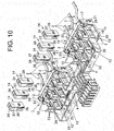
- the press fixing member 15 is arranged facing the supporting piece 25 of the terminal holder 12 along a direction perpendicular to (crossing) the longitudinal direction of the electric contact section 6 and the thin-walled section 9 held in the terminal holder 12, the press fixing member 15 is inserted into between the pair of vertically extended pieces 17 of the base 11. Then, as shown in Fig. 10 , when the engaging projection 42 is engaged with the engaging hole 21, the press fixing member 15 is attached to the base 11. At this time, of course, the press fixing member 15 pushes the coil connecting section 5 of the first terminal fixture 3 toward the bottom wall 16 of the base 11.
- the clip connector 14 is arranged facing an interval between the pair of vertically extended pillars 23 of the terminal holder 12 along a direction perpendicular to (crossing) the longitudinal direction of the electric contact section 6 and the thin-walled section 9 held in the terminal holder 12, the clip connector 14 is inserted between the pair of vertically extended pillars 23. Then, when the locking projections 39 are locked with the coupling beams 24, the clip connector 14 is attached to the terminal holder 12. At this time, of course, when the clip connector 14 is moved close to the terminal holder 12, the electric contact section 6 of the first terminal fixture 3 and the thin-walled section 9 of the busbar 4 are caught between the pair of contact pieces 35 of the clip terminal 33.
- the terminal connection structure 1 is assembled, and the busbar 4 and the first terminal fixture 3 are connected to each other. Then, when busbars 43 connected to the inverter as the other power device and a joint connector 44 are attached to the connector housing 10, the motor as the one power device and the inverter as the other power device are connected to each other. Further, the terminal connection structure 1 assembled as above described is received in a housing of the motor or the like.
- the terminal holder 12 when the bottom plate section 22 as the parallel wall provided on one of the terminal holder 12 and the base 11 is inserted into the holding slit 29 that is larger than the bottom plate section 22, the terminal holder 12 becomes movable in a direction parallel to a surface of the bottom wall 16 of the base 11. Therefore, there is nothing that prevents the terminal holder 12 from moving other than an inner wall of the holding slit 29. Therefore, the terminal holder 12 becomes movable with respect to the bottom wall 16 of the base 11 within a gap between the holding slit 29 and the bottom plate section 22. Therefore, by adjusting properly a size of the holding slit 29, the first terminal fixture 3 can be moved widely with respect to the base 11, and even if the positional offset between the first terminal fixture 3 and the busbar 4 is great, they are surely connected to each other.
- the clip terminal 33 includes the pair of contact pieces 35 and the bias coupling section 36 biasing the pair of contact pieces 35 toward a direction close to each other, the electric contact section 6 and the thin-walled section 9 overlapped with each other can be held between the pair of contact pieces 35. Therefore, the first terminal fixture 3 and the busbar 4 can be surely and electrically connected to each other.
- the terminal connection structure 1 includes the clip terminal holder 34 covering the clip terminal 33 and locked with the terminal holder 12, the clip terminal holder 34 prevents the clip terminal 33 from falling out. Therefore, a connection between the first terminal fixture 3 and the busbar 4 is prevented from being released unexpectedly.
- the terminal connection structure 1 includes the press fixing member 15 pressing the first terminal fixture 3 toward the bottom wall 16 of the base 11 when attached to the base 11, the first terminal fixture 3 can be positioned in a thickness direction of the bottom wall 16 of the base 11 by the press fixing member 15.
- the holding slit 29 is provided on the base 11, and the bottom plate section 22 as the parallel wall is provided on the terminal holder 12.
Landscapes
- Connector Housings Or Holding Contact Members (AREA)
- Details Of Connecting Devices For Male And Female Coupling (AREA)
- Connections Arranged To Contact A Plurality Of Conductors (AREA)
Claims (3)
- Structure de connexion de borne (1) destinée à connecter un second dispositif de borne (4) à un premier dispositif de borne (3) qui est raccordé à un dispositif de puissance,
ladite structure de connexion de borne (1) comprenant :une base (10) comportant une paroi de fond (16)un support de borne (12) qui peut soutenir les premier et second dispositifs de borne (3, 4) pour qu'ils se chevauchent, etune section de fixation mobile (13) comportant une paroi parallèle (22) qui est disposée sur le support de borne (12) et qui est parallèle à la paroi de fond (16), ainsi qu'une fente de support (29) qui est disposée dans la base (11), dans laquelle entre la paroi parallèle (22) et qui est plus large que la paroi parallèle (22) ; et elle fixe le support de borne (12) à la base (11) pour qu'il soit mobile et parallèle à la surface de la paroi de fond (16),caractérisée en ce qu'elle comprend un élément de fixation par pression (15) configuré pour être fixé à la base (11),dans laquelle l'élément de fixation par pression (15) est configuré pour venir en butée sur une section de connexion (5) raccordée au dispositif de puissance du premier dispositif de borne (3) et pour pousser la section de connexion (5) vers la paroi de fond (16) lorsqu'elle est fixée à la base (11),dans laquelle le support de borne (12) inclut une section de plaque de fond (22) utilisée comme paroi parallèle, une paire de montants allongés (23) s'étendant verticalement depuis la section de plaque de fond (22) et parallèles à l'un à l'autre, un espace étant ménagé entre eux, ainsi qu'une pièce de support (25) sur laquelle doit être placée la section de connexion (5) du premier dispositif de borne (3),dans laquelle un premier de la paire de montants allongés (23) inclut un trou traversant (26) au travers duquel doit être passé le second dispositif de borne (4), et où un autre de la paire de montants allongés (23) inclut une fente (27) dans laquelle doit être reçu le premier dispositif de borne (3), etdans laquelle la pièce de support (25) s'étend depuis l'autre de la paire de montants allongés (23) dans une direction s'éloignant du premier de la paire de montants allongés (23). - Structure de connexion de borne (1) selon la revendication 1, comprenant en outre :une borne à agrafe (33) comportant une paire de pièces de contact (35) destinées à soutenir les premier et second dispositifs de borne (3, 4) pour qu'ils se chevauchent, ainsi qu'une section d'accouplement par déformation (36) qui se poursuit jusqu'à la paire de pièces de contact (35) et qui contraint la paire de pièces de contact (35) supportant les premier et second dispositifs de borne (3, 4) dans un sens qui les rapproche,ladite borne à agrafe (33) est configurée pour être déplacée à proximité du support de borne (12) dans un sens croisant les premier et second dispositifs de borne (3, 4) qui se chevauchent ; et elle est fixée au support de borne (12) avec la paire de pièces de contact (35) soutenant les premier et second dispositifs de borne (3, 4) pour qu'ils se chevauchent.
- Structure de connexion de borne (1) selon la revendication 2, comprenant en outre :
un support de borne à agrafe (34) recouvrant la borne à agrafe (33) et comportant une section de fixation devant être verrouillée avec le support de borne (12).
Applications Claiming Priority (2)
| Application Number | Priority Date | Filing Date | Title |
|---|---|---|---|
| JP2010223681A JP5666232B2 (ja) | 2010-10-01 | 2010-10-01 | 端子接続構造 |
| PCT/JP2011/072457 WO2012043760A1 (fr) | 2010-10-01 | 2011-09-29 | Structure de connexion de borne |
Publications (3)
| Publication Number | Publication Date |
|---|---|
| EP2624367A1 EP2624367A1 (fr) | 2013-08-07 |
| EP2624367A4 EP2624367A4 (fr) | 2014-04-02 |
| EP2624367B1 true EP2624367B1 (fr) | 2019-07-24 |
Family
ID=45893197
Family Applications (1)
| Application Number | Title | Priority Date | Filing Date |
|---|---|---|---|
| EP11829313.3A Active EP2624367B1 (fr) | 2010-10-01 | 2011-09-29 | Structure de connexion de borne |
Country Status (5)
| Country | Link |
|---|---|
| US (1) | US9054442B2 (fr) |
| EP (1) | EP2624367B1 (fr) |
| JP (1) | JP5666232B2 (fr) |
| CN (1) | CN103140987B (fr) |
| WO (1) | WO2012043760A1 (fr) |
Families Citing this family (12)
| Publication number | Priority date | Publication date | Assignee | Title |
|---|---|---|---|---|
| JP5657984B2 (ja) * | 2010-10-01 | 2015-01-21 | 矢崎総業株式会社 | 端子接続構造 |
| JP6024985B2 (ja) * | 2013-05-30 | 2016-11-16 | 株式会社オートネットワーク技術研究所 | 端子台 |
| JP6157640B2 (ja) | 2013-12-12 | 2017-07-05 | 矢崎総業株式会社 | バッテリー端子 |
| US9698402B2 (en) * | 2014-03-13 | 2017-07-04 | Ford Global Technologies, Llc | Method of welding a bus bar to battery cell terminals |
| JP2019110074A (ja) | 2017-12-20 | 2019-07-04 | 矢崎総業株式会社 | 接続端子及びコネクタ |
| JP6951669B2 (ja) | 2018-06-04 | 2021-10-20 | 株式会社オートネットワーク技術研究所 | コネクタ及びコネクタ装置 |
| JP7080562B2 (ja) * | 2018-07-05 | 2022-06-06 | 矢崎総業株式会社 | 電気配線ブロック接合体、電気接続箱及びワイヤハーネス |
| JP7001047B2 (ja) | 2018-12-14 | 2022-01-19 | オムロン株式会社 | 端子台 |
| DE112020000459T5 (de) * | 2019-01-21 | 2021-11-25 | Royal Precision Products, Llc | Stromverteilungsanordnung mit schraubenlosem sammelschienensystem |
| CN113451813B (zh) * | 2020-03-26 | 2025-06-27 | 安波福中央电气(上海)有限公司 | 汇流排组件 |
| JP7548161B2 (ja) * | 2020-11-12 | 2024-09-10 | 株式会社オートネットワーク技術研究所 | コネクタおよびコネクタ装置 |
| WO2022102698A1 (fr) * | 2020-11-12 | 2022-05-19 | 株式会社オートネットワーク技術研究所 | Connecteur et dispositif connecteur |
Citations (1)
| Publication number | Priority date | Publication date | Assignee | Title |
|---|---|---|---|---|
| US4910641A (en) * | 1988-02-18 | 1990-03-20 | Yazaki Corporation | Wire harness apparatus for instrument panel |
Family Cites Families (16)
| Publication number | Priority date | Publication date | Assignee | Title |
|---|---|---|---|---|
| JPH03104973U (fr) * | 1990-02-15 | 1991-10-30 | ||
| US6896674B1 (en) * | 1993-05-10 | 2005-05-24 | Arthrocare Corporation | Electrosurgical apparatus having digestion electrode and methods related thereto |
| US5893768A (en) * | 1996-12-18 | 1999-04-13 | Ut Automotive Dearborn, Inc. | Self-aligning connection system |
| US6159030A (en) * | 1997-06-16 | 2000-12-12 | Lear Automotive Dearborn, Inc. | Self-aligning connecting system |
| JP2001126821A (ja) * | 1999-10-27 | 2001-05-11 | Sumitomo Wiring Syst Ltd | コネクタの取付構造 |
| JP4477201B2 (ja) * | 2000-07-05 | 2010-06-09 | 古河電気工業株式会社 | コネクタ及びそれに用いる端子 |
| JP2002093531A (ja) | 2000-09-11 | 2002-03-29 | Yazaki Corp | 自動調心型の電気コネクタ |
| CA2363530A1 (fr) * | 2001-11-20 | 2003-05-20 | Fci Americas Technology Inc. | Connexion semi-permanente entre une barre omnibus et un contact de connecteur |
| JP3997208B2 (ja) * | 2004-02-17 | 2007-10-24 | トヨタ自動車株式会社 | コネクタの固定構造 |
| JP3104973U (ja) | 2004-05-02 | 2004-10-21 | 康豪 高嶋 | 微生物を利用した生ゴミ処理装置 |
| JP4330502B2 (ja) * | 2004-08-11 | 2009-09-16 | 三洋電機株式会社 | フローティング構造のコネクタ |
| JP4547282B2 (ja) * | 2005-03-07 | 2010-09-22 | 株式会社フジクラ | 自動調芯用コネクタ |
| JP2007234322A (ja) * | 2006-02-28 | 2007-09-13 | Mitsubishi Cable Ind Ltd | フラットケーブルの接続構造 |
| TWM308546U (en) * | 2006-07-07 | 2007-03-21 | Powertech Ind Co Ltd | Connection device for conductive sheet |
| US8173920B2 (en) * | 2007-04-23 | 2012-05-08 | Lutron Electronics Co., Inc. | Load control device having a modular assembly |
| JP2009283391A (ja) * | 2008-05-26 | 2009-12-03 | Kyocera Corp | 接続構造 |
-
2010
- 2010-10-01 JP JP2010223681A patent/JP5666232B2/ja active Active
-
2011
- 2011-09-29 WO PCT/JP2011/072457 patent/WO2012043760A1/fr not_active Ceased
- 2011-09-29 EP EP11829313.3A patent/EP2624367B1/fr active Active
- 2011-09-29 CN CN201180047761.7A patent/CN103140987B/zh active Active
- 2011-09-29 US US13/876,720 patent/US9054442B2/en active Active
Patent Citations (1)
| Publication number | Priority date | Publication date | Assignee | Title |
|---|---|---|---|---|
| US4910641A (en) * | 1988-02-18 | 1990-03-20 | Yazaki Corporation | Wire harness apparatus for instrument panel |
Also Published As
| Publication number | Publication date |
|---|---|
| EP2624367A4 (fr) | 2014-04-02 |
| CN103140987B (zh) | 2016-03-02 |
| JP5666232B2 (ja) | 2015-02-12 |
| US9054442B2 (en) | 2015-06-09 |
| US20130196558A1 (en) | 2013-08-01 |
| WO2012043760A1 (fr) | 2012-04-05 |
| JP2012079545A (ja) | 2012-04-19 |
| EP2624367A1 (fr) | 2013-08-07 |
| CN103140987A (zh) | 2013-06-05 |
Similar Documents
| Publication | Publication Date | Title |
|---|---|---|
| EP2624367B1 (fr) | Structure de connexion de borne | |
| US8684759B2 (en) | Terminal connection structure | |
| US8870131B2 (en) | Wiring harness fixture | |
| US10056596B2 (en) | Battery connector assembly | |
| US8765289B2 (en) | Power supply unit with bus bar module | |
| US9780351B2 (en) | Wiring module | |
| US7438604B2 (en) | Distributor block | |
| US10468841B2 (en) | Bus bar header assembly | |
| US8888540B2 (en) | Power-track coupling | |
| WO2014085123A1 (fr) | Ensemble connecteur d'alimentation ayant un corps d'alignement | |
| EP2876704A1 (fr) | Module de barre omnibus | |
| KR20150033734A (ko) | 전자 부품, 전자 부품과 단자 금구와의 접속 구조, 전자 부품을 가지는 전기 접속 상자 | |
| EP3091618B1 (fr) | Contact femelle et connecteur d'alimentation électrique | |
| JP2003022855A (ja) | ホルダ | |
| US9806440B2 (en) | Terminal block | |
| JP7152364B2 (ja) | 電線保持構造及びバスバーモジュール | |
| EP3037304B1 (fr) | Boîte de connexion électrique pour véhicule | |
| US20110232960A1 (en) | Component-equipped-holder mounting structure | |
| AU2019398165A1 (en) | Plug connector part for contacting in multiple spatial directions | |
| CN219759395U (zh) | 一种汽车维修开关 | |
| JP2022172847A (ja) | 接続部品 | |
| EP4348770A1 (fr) | Borne femelle tubulaire à courant élevé | |
| JP2006073324A (ja) | 端子金具及びコネクタ |
Legal Events
| Date | Code | Title | Description |
|---|---|---|---|
| PUAI | Public reference made under article 153(3) epc to a published international application that has entered the european phase |
Free format text: ORIGINAL CODE: 0009012 |
|
| 17P | Request for examination filed |
Effective date: 20130409 |
|
| AK | Designated contracting states |
Kind code of ref document: A1 Designated state(s): AL AT BE BG CH CY CZ DE DK EE ES FI FR GB GR HR HU IE IS IT LI LT LU LV MC MK MT NL NO PL PT RO RS SE SI SK SM TR |
|
| DAX | Request for extension of the european patent (deleted) | ||
| A4 | Supplementary search report drawn up and despatched |
Effective date: 20140227 |
|
| RIC1 | Information provided on ipc code assigned before grant |
Ipc: H01R 13/631 20060101AFI20140221BHEP Ipc: H01R 4/48 20060101ALN20140221BHEP Ipc: H01R 25/14 20060101ALN20140221BHEP Ipc: H01R 13/193 20060101ALN20140221BHEP |
|
| 17Q | First examination report despatched |
Effective date: 20160229 |
|
| STAA | Information on the status of an ep patent application or granted ep patent |
Free format text: STATUS: EXAMINATION IS IN PROGRESS |
|
| REG | Reference to a national code |
Ref country code: DE Ref legal event code: R079 Ref document number: 602011060766 Country of ref document: DE Free format text: PREVIOUS MAIN CLASS: H01R0004480000 Ipc: H01R0013631000 |
|
| GRAP | Despatch of communication of intention to grant a patent |
Free format text: ORIGINAL CODE: EPIDOSNIGR1 |
|
| STAA | Information on the status of an ep patent application or granted ep patent |
Free format text: STATUS: GRANT OF PATENT IS INTENDED |
|
| RIC1 | Information provided on ipc code assigned before grant |
Ipc: H01R 13/631 20060101AFI20190212BHEP Ipc: H01R 13/193 20060101ALN20190212BHEP Ipc: H01R 25/14 20060101ALN20190212BHEP Ipc: H01R 4/48 20060101ALN20190212BHEP |
|
| INTG | Intention to grant announced |
Effective date: 20190318 |
|
| GRAS | Grant fee paid |
Free format text: ORIGINAL CODE: EPIDOSNIGR3 |
|
| GRAA | (expected) grant |
Free format text: ORIGINAL CODE: 0009210 |
|
| STAA | Information on the status of an ep patent application or granted ep patent |
Free format text: STATUS: THE PATENT HAS BEEN GRANTED |
|
| AK | Designated contracting states |
Kind code of ref document: B1 Designated state(s): AL AT BE BG CH CY CZ DE DK EE ES FI FR GB GR HR HU IE IS IT LI LT LU LV MC MK MT NL NO PL PT RO RS SE SI SK SM TR |
|
| REG | Reference to a national code |
Ref country code: GB Ref legal event code: FG4D |
|
| REG | Reference to a national code |
Ref country code: CH Ref legal event code: EP |
|
| REG | Reference to a national code |
Ref country code: DE Ref legal event code: R096 Ref document number: 602011060766 Country of ref document: DE |
|
| REG | Reference to a national code |
Ref country code: AT Ref legal event code: REF Ref document number: 1159325 Country of ref document: AT Kind code of ref document: T Effective date: 20190815 |
|
| REG | Reference to a national code |
Ref country code: IE Ref legal event code: FG4D |
|
| REG | Reference to a national code |
Ref country code: NL Ref legal event code: MP Effective date: 20190724 |
|
| REG | Reference to a national code |
Ref country code: LT Ref legal event code: MG4D |
|
| REG | Reference to a national code |
Ref country code: AT Ref legal event code: MK05 Ref document number: 1159325 Country of ref document: AT Kind code of ref document: T Effective date: 20190724 |
|
| PG25 | Lapsed in a contracting state [announced via postgrant information from national office to epo] |
Ref country code: BG Free format text: LAPSE BECAUSE OF FAILURE TO SUBMIT A TRANSLATION OF THE DESCRIPTION OR TO PAY THE FEE WITHIN THE PRESCRIBED TIME-LIMIT Effective date: 20191024 Ref country code: NO Free format text: LAPSE BECAUSE OF FAILURE TO SUBMIT A TRANSLATION OF THE DESCRIPTION OR TO PAY THE FEE WITHIN THE PRESCRIBED TIME-LIMIT Effective date: 20191024 Ref country code: SE Free format text: LAPSE BECAUSE OF FAILURE TO SUBMIT A TRANSLATION OF THE DESCRIPTION OR TO PAY THE FEE WITHIN THE PRESCRIBED TIME-LIMIT Effective date: 20190724 Ref country code: PT Free format text: LAPSE BECAUSE OF FAILURE TO SUBMIT A TRANSLATION OF THE DESCRIPTION OR TO PAY THE FEE WITHIN THE PRESCRIBED TIME-LIMIT Effective date: 20191125 Ref country code: NL Free format text: LAPSE BECAUSE OF FAILURE TO SUBMIT A TRANSLATION OF THE DESCRIPTION OR TO PAY THE FEE WITHIN THE PRESCRIBED TIME-LIMIT Effective date: 20190724 Ref country code: LT Free format text: LAPSE BECAUSE OF FAILURE TO SUBMIT A TRANSLATION OF THE DESCRIPTION OR TO PAY THE FEE WITHIN THE PRESCRIBED TIME-LIMIT Effective date: 20190724 Ref country code: AT Free format text: LAPSE BECAUSE OF FAILURE TO SUBMIT A TRANSLATION OF THE DESCRIPTION OR TO PAY THE FEE WITHIN THE PRESCRIBED TIME-LIMIT Effective date: 20190724 Ref country code: FI Free format text: LAPSE BECAUSE OF FAILURE TO SUBMIT A TRANSLATION OF THE DESCRIPTION OR TO PAY THE FEE WITHIN THE PRESCRIBED TIME-LIMIT Effective date: 20190724 Ref country code: HR Free format text: LAPSE BECAUSE OF FAILURE TO SUBMIT A TRANSLATION OF THE DESCRIPTION OR TO PAY THE FEE WITHIN THE PRESCRIBED TIME-LIMIT Effective date: 20190724 |
|
| PG25 | Lapsed in a contracting state [announced via postgrant information from national office to epo] |
Ref country code: AL Free format text: LAPSE BECAUSE OF FAILURE TO SUBMIT A TRANSLATION OF THE DESCRIPTION OR TO PAY THE FEE WITHIN THE PRESCRIBED TIME-LIMIT Effective date: 20190724 Ref country code: LV Free format text: LAPSE BECAUSE OF FAILURE TO SUBMIT A TRANSLATION OF THE DESCRIPTION OR TO PAY THE FEE WITHIN THE PRESCRIBED TIME-LIMIT Effective date: 20190724 Ref country code: IS Free format text: LAPSE BECAUSE OF FAILURE TO SUBMIT A TRANSLATION OF THE DESCRIPTION OR TO PAY THE FEE WITHIN THE PRESCRIBED TIME-LIMIT Effective date: 20191124 Ref country code: GR Free format text: LAPSE BECAUSE OF FAILURE TO SUBMIT A TRANSLATION OF THE DESCRIPTION OR TO PAY THE FEE WITHIN THE PRESCRIBED TIME-LIMIT Effective date: 20191025 Ref country code: RS Free format text: LAPSE BECAUSE OF FAILURE TO SUBMIT A TRANSLATION OF THE DESCRIPTION OR TO PAY THE FEE WITHIN THE PRESCRIBED TIME-LIMIT Effective date: 20190724 Ref country code: ES Free format text: LAPSE BECAUSE OF FAILURE TO SUBMIT A TRANSLATION OF THE DESCRIPTION OR TO PAY THE FEE WITHIN THE PRESCRIBED TIME-LIMIT Effective date: 20190724 |
|
| PG25 | Lapsed in a contracting state [announced via postgrant information from national office to epo] |
Ref country code: TR Free format text: LAPSE BECAUSE OF FAILURE TO SUBMIT A TRANSLATION OF THE DESCRIPTION OR TO PAY THE FEE WITHIN THE PRESCRIBED TIME-LIMIT Effective date: 20190724 |
|
| PG25 | Lapsed in a contracting state [announced via postgrant information from national office to epo] |
Ref country code: DK Free format text: LAPSE BECAUSE OF FAILURE TO SUBMIT A TRANSLATION OF THE DESCRIPTION OR TO PAY THE FEE WITHIN THE PRESCRIBED TIME-LIMIT Effective date: 20190724 Ref country code: EE Free format text: LAPSE BECAUSE OF FAILURE TO SUBMIT A TRANSLATION OF THE DESCRIPTION OR TO PAY THE FEE WITHIN THE PRESCRIBED TIME-LIMIT Effective date: 20190724 Ref country code: IT Free format text: LAPSE BECAUSE OF FAILURE TO SUBMIT A TRANSLATION OF THE DESCRIPTION OR TO PAY THE FEE WITHIN THE PRESCRIBED TIME-LIMIT Effective date: 20190724 Ref country code: PL Free format text: LAPSE BECAUSE OF FAILURE TO SUBMIT A TRANSLATION OF THE DESCRIPTION OR TO PAY THE FEE WITHIN THE PRESCRIBED TIME-LIMIT Effective date: 20190724 Ref country code: RO Free format text: LAPSE BECAUSE OF FAILURE TO SUBMIT A TRANSLATION OF THE DESCRIPTION OR TO PAY THE FEE WITHIN THE PRESCRIBED TIME-LIMIT Effective date: 20190724 |
|
| PG25 | Lapsed in a contracting state [announced via postgrant information from national office to epo] |
Ref country code: MC Free format text: LAPSE BECAUSE OF FAILURE TO SUBMIT A TRANSLATION OF THE DESCRIPTION OR TO PAY THE FEE WITHIN THE PRESCRIBED TIME-LIMIT Effective date: 20190724 Ref country code: CZ Free format text: LAPSE BECAUSE OF FAILURE TO SUBMIT A TRANSLATION OF THE DESCRIPTION OR TO PAY THE FEE WITHIN THE PRESCRIBED TIME-LIMIT Effective date: 20190724 Ref country code: SK Free format text: LAPSE BECAUSE OF FAILURE TO SUBMIT A TRANSLATION OF THE DESCRIPTION OR TO PAY THE FEE WITHIN THE PRESCRIBED TIME-LIMIT Effective date: 20190724 Ref country code: SM Free format text: LAPSE BECAUSE OF FAILURE TO SUBMIT A TRANSLATION OF THE DESCRIPTION OR TO PAY THE FEE WITHIN THE PRESCRIBED TIME-LIMIT Effective date: 20190724 Ref country code: IS Free format text: LAPSE BECAUSE OF FAILURE TO SUBMIT A TRANSLATION OF THE DESCRIPTION OR TO PAY THE FEE WITHIN THE PRESCRIBED TIME-LIMIT Effective date: 20200224 |
|
| REG | Reference to a national code |
Ref country code: CH Ref legal event code: PL |
|
| REG | Reference to a national code |
Ref country code: DE Ref legal event code: R097 Ref document number: 602011060766 Country of ref document: DE |
|
| PLBE | No opposition filed within time limit |
Free format text: ORIGINAL CODE: 0009261 |
|
| STAA | Information on the status of an ep patent application or granted ep patent |
Free format text: STATUS: NO OPPOSITION FILED WITHIN TIME LIMIT |
|
| PG2D | Information on lapse in contracting state deleted |
Ref country code: IS |
|
| PG25 | Lapsed in a contracting state [announced via postgrant information from national office to epo] |
Ref country code: LU Free format text: LAPSE BECAUSE OF NON-PAYMENT OF DUE FEES Effective date: 20190929 Ref country code: IE Free format text: LAPSE BECAUSE OF NON-PAYMENT OF DUE FEES Effective date: 20190929 Ref country code: CH Free format text: LAPSE BECAUSE OF NON-PAYMENT OF DUE FEES Effective date: 20190930 Ref country code: LI Free format text: LAPSE BECAUSE OF NON-PAYMENT OF DUE FEES Effective date: 20190930 |
|
| 26N | No opposition filed |
Effective date: 20200603 |
|
| REG | Reference to a national code |
Ref country code: BE Ref legal event code: MM Effective date: 20190930 |
|
| PG25 | Lapsed in a contracting state [announced via postgrant information from national office to epo] |
Ref country code: BE Free format text: LAPSE BECAUSE OF NON-PAYMENT OF DUE FEES Effective date: 20190930 Ref country code: SI Free format text: LAPSE BECAUSE OF FAILURE TO SUBMIT A TRANSLATION OF THE DESCRIPTION OR TO PAY THE FEE WITHIN THE PRESCRIBED TIME-LIMIT Effective date: 20190724 |
|
| GBPC | Gb: european patent ceased through non-payment of renewal fee |
Effective date: 20191024 |
|
| PG25 | Lapsed in a contracting state [announced via postgrant information from national office to epo] |
Ref country code: GB Free format text: LAPSE BECAUSE OF NON-PAYMENT OF DUE FEES Effective date: 20191024 |
|
| PG25 | Lapsed in a contracting state [announced via postgrant information from national office to epo] |
Ref country code: CY Free format text: LAPSE BECAUSE OF FAILURE TO SUBMIT A TRANSLATION OF THE DESCRIPTION OR TO PAY THE FEE WITHIN THE PRESCRIBED TIME-LIMIT Effective date: 20190724 |
|
| PG25 | Lapsed in a contracting state [announced via postgrant information from national office to epo] |
Ref country code: MT Free format text: LAPSE BECAUSE OF FAILURE TO SUBMIT A TRANSLATION OF THE DESCRIPTION OR TO PAY THE FEE WITHIN THE PRESCRIBED TIME-LIMIT Effective date: 20190724 Ref country code: HU Free format text: LAPSE BECAUSE OF FAILURE TO SUBMIT A TRANSLATION OF THE DESCRIPTION OR TO PAY THE FEE WITHIN THE PRESCRIBED TIME-LIMIT; INVALID AB INITIO Effective date: 20110929 |
|
| PG25 | Lapsed in a contracting state [announced via postgrant information from national office to epo] |
Ref country code: MK Free format text: LAPSE BECAUSE OF FAILURE TO SUBMIT A TRANSLATION OF THE DESCRIPTION OR TO PAY THE FEE WITHIN THE PRESCRIBED TIME-LIMIT Effective date: 20190724 |
|
| PGFP | Annual fee paid to national office [announced via postgrant information from national office to epo] |
Ref country code: DE Payment date: 20240806 Year of fee payment: 14 |
|
| PGFP | Annual fee paid to national office [announced via postgrant information from national office to epo] |
Ref country code: FR Payment date: 20240808 Year of fee payment: 14 |