EP2624437A2 - Dispositif de commande de moteur et procédé de commande de celui-ci - Google Patents
Dispositif de commande de moteur et procédé de commande de celui-ci Download PDFInfo
- Publication number
- EP2624437A2 EP2624437A2 EP13151414.3A EP13151414A EP2624437A2 EP 2624437 A2 EP2624437 A2 EP 2624437A2 EP 13151414 A EP13151414 A EP 13151414A EP 2624437 A2 EP2624437 A2 EP 2624437A2
- Authority
- EP
- European Patent Office
- Prior art keywords
- switch
- electric power
- power source
- motor
- capacitor
- Prior art date
- Legal status (The legal status is an assumption and is not a legal conclusion. Google has not performed a legal analysis and makes no representation as to the accuracy of the status listed.)
- Granted
Links
Images
Classifications
-
- H—ELECTRICITY
- H02—GENERATION; CONVERSION OR DISTRIBUTION OF ELECTRIC POWER
- H02P—CONTROL OR REGULATION OF ELECTRIC MOTORS, ELECTRIC GENERATORS OR DYNAMO-ELECTRIC CONVERTERS; CONTROLLING TRANSFORMERS, REACTORS OR CHOKE COILS
- H02P3/00—Arrangements for stopping or slowing electric motors, generators, or dynamo-electric converters
- H02P3/06—Arrangements for stopping or slowing electric motors, generators, or dynamo-electric converters for stopping or slowing an individual dynamo-electric motor or dynamo-electric converter
- H02P3/08—Arrangements for stopping or slowing electric motors, generators, or dynamo-electric converters for stopping or slowing an individual dynamo-electric motor or dynamo-electric converter for stopping or slowing a DC motor
- H02P3/12—Arrangements for stopping or slowing electric motors, generators, or dynamo-electric converters for stopping or slowing an individual dynamo-electric motor or dynamo-electric converter for stopping or slowing a DC motor by short-circuit or resistive braking
-
- H—ELECTRICITY
- H02—GENERATION; CONVERSION OR DISTRIBUTION OF ELECTRIC POWER
- H02P—CONTROL OR REGULATION OF ELECTRIC MOTORS, ELECTRIC GENERATORS OR DYNAMO-ELECTRIC CONVERTERS; CONTROLLING TRANSFORMERS, REACTORS OR CHOKE COILS
- H02P3/00—Arrangements for stopping or slowing electric motors, generators, or dynamo-electric converters
- H02P3/02—Details of stopping control
-
- H—ELECTRICITY
- H02—GENERATION; CONVERSION OR DISTRIBUTION OF ELECTRIC POWER
- H02P—CONTROL OR REGULATION OF ELECTRIC MOTORS, ELECTRIC GENERATORS OR DYNAMO-ELECTRIC CONVERTERS; CONTROLLING TRANSFORMERS, REACTORS OR CHOKE COILS
- H02P3/00—Arrangements for stopping or slowing electric motors, generators, or dynamo-electric converters
- H02P3/06—Arrangements for stopping or slowing electric motors, generators, or dynamo-electric converters for stopping or slowing an individual dynamo-electric motor or dynamo-electric converter
- H02P3/18—Arrangements for stopping or slowing electric motors, generators, or dynamo-electric converters for stopping or slowing an individual dynamo-electric motor or dynamo-electric converter for stopping or slowing an AC motor
- H02P3/22—Arrangements for stopping or slowing electric motors, generators, or dynamo-electric converters for stopping or slowing an individual dynamo-electric motor or dynamo-electric converter for stopping or slowing an AC motor by short-circuit or resistive braking
-
- H—ELECTRICITY
- H02—GENERATION; CONVERSION OR DISTRIBUTION OF ELECTRIC POWER
- H02P—CONTROL OR REGULATION OF ELECTRIC MOTORS, ELECTRIC GENERATORS OR DYNAMO-ELECTRIC CONVERTERS; CONTROLLING TRANSFORMERS, REACTORS OR CHOKE COILS
- H02P6/00—Arrangements for controlling synchronous motors or other dynamo-electric motors using electronic commutation dependent on the rotor position; Electronic commutators therefor
- H02P6/24—Arrangements for stopping
Definitions
- the present invention relates to a motor control device and a control method of the same, which can apply an electric brake to a motor when power supply is stopped.
- Patent Literature 1 Japanese Patent No. 4451431
- Patent Literature 1 when power supply is stopped, a starting device and a driving device which short-circuit a coil of a motor, using power accumulated in a power accumulation device. Since the power accumulation device is required to accumulate the power for operating two devices of the starting device and the drive device, a capacitor provided in the power accumulation device naturally has a large capacitance.
- the large capacitance of the capacitor leads to difficulty with a miniaturization of a motor control device, and leads to difficulty with a cost reduction of the motor control device.
- the present invention is made in order to reduce such obstacle in conventional technique, and has an object to provide a motor control device and its control method which can apply an electric brake to a motor when power supply is stopped, and achieve a miniaturization and a cost reduction.
- a motor control device for achieving the above-described object according to the present invention includes a switch group, a capacitor, and a connection switch at the time of stopping electric power supply.
- the switch group connects each coil included in a motor to an electric power source.
- the capacitor accumulates power supplied from the electric power source.
- the connection switch at the time of stopping electric power supply connects the capacitor and a part of switches forming the switch group, when power supply from the electric power source is stopped.
- the part of switches forming the switch group are operated by the power accumulated in the capacitor by an operation of the connection switch at the time of stopping electric power supply, and each coil is short-circuited by an operation of the part of switches to apply a brake to the motor.
- the motor control device includes: a switch group which connects each coil included in a motor to an electric power source; a capacitor which accumulates power supplied from the electric power source; and a connection switch at the time of stopping electric power supply, which connects the capacitor and a part of switches forming the switch group, when power supply from the electric power source is stopped, the control method includes steps of: operating the switch group to connect respective coils to the electric power source in order, to rotate the motor; and when power supply from the electric power source is stopped, operating the part of switches forming the switch group by the power accumulated in the capacitor by an operation of the connection switch at the time of stopping electric power supply, and short-circuiting each coil by an operation of the part of switches to apply a brake to the motor.
- the capacitor for operating a part of switches which constitute a switch group when power supply from an electric power source has a small capacitance to the extent that the capacitor can accumulate electric power required to operate the part of switches.
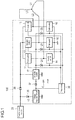
- Fig. 1 is a block diagram of the motor control device according to the present embodiment.
- a first switch 11, a second switch 12, a third switch 13, a fourth switch 14, a fifth switch 15, and a sixth switch 16 included in a motor control device 100 connects coils L1, L2 and L3 included in a motor to an electric power source 20.
- the first switch 11, the second switch 12, the third switch 13, the fourth switch 14, the fifth switch 15, and the sixth switch 16 form a switch group.
- the motor exemplified in the present embodiment is a three-phase motor which includes the three coils L1, L2 and L3 connected in star connection, and drives a cooling fan which cools components of various control devices.
- first switch 11, the second switch 12, and the third switch 13 are connected to the electric power source 20 through a diode 36.
- the other ends of first switch 11, the second switch 12 and the third switch 13 are connected to the ends of the fourth switch 14, the fifth switch 15 and the sixth switch 16, respectively.
- the other ends of the fourth switch 14, the fifth switch 15, and the sixth switch 16 are grounded.
- the coil L1 is connected to a line which connects the first switch 11 and the fourth switch 14.
- the coil L2 is connected to a line which connects the second switch 12 and the fifth switch 15.
- the coil L3 is connected to a line which connects the third switch 13 and the sixth switch 16.
- the first switch 11, the second switch 12, the third switch 13, the fourth switch 14, the fifth switch 15, and the sixth switch 16 are connected to a drive circuit 30.
- the drive circuit 30, when the power is supplied from the electric power source 20, individually controls ON and OFF of the first switch 11, the second switch 12, the third switch 13, the fourth switch 14, the fifth switch 15, and the sixth switch 16.
- the drive circuit 30 turns on and turns off the first switch 11, the second switch 12, the third switch 13, the fourth switch 14, the fifth switch 15, and the sixth switch 16 according to predetermined combinations and timing, whereby connecting the coils L1, L2, and L3 to the electric power source 20 in order.
- the current which flows in the coils L1, L2, and L3 rotates the motor, and rotates the cooling fan.
- the drive circuit 30 is connected to a voltage regulator circuit 40.
- the voltage regulator circuit 40 is connected to the electric power source 20 through a diode 35.
- the voltage regulator circuit 40 regulates voltage from the electric power source 20 to maintain constant voltage, and supplies the constant voltage to the drive circuit 30.
- the voltage regulator circuit 40 is connected to the seventh switch 17 through the diode 37.
- a capacitor C is connected between the diode 37 and the seventh switch 17.
- the capacitor C accumulates the power supplied from the voltage regulator circuit 40, when power is supplied from the electric power source 20.
- the capacitor C is only necessary to have capacitance which can accumulate the power required to operate the fourth switch 14, the fifth switch 15, and the sixth switch 16 for a predetermined time.
- the power for turning on the fourth switch 14, the fifth switch 15, and the sixth switches 16 at once in a short time such as about for 1 second is extremely small. Therefore, the capacitor C only needs small capacitance, and the miniaturization and the cost reduction of the motor control device 100 can be achieved.
- the seventh switch 17 is connected to the electric power source 20 through the diode 36.
- the seventh switch 17 is connected to the fourth switch 14 through the diode 24, is connected to the fifth switch 15 through the diode 25 and is connected to the sixth switch 16 through the diode 26, respectively.
- the fourth switch 14, the fifth switch 15, and the sixth switches 16 are a part of switches which form the switch group.
- the capacitor C accumulates the power supplied from the voltage regulator circuit 40 connected to the electric power source 20.
- the seventh switch 17 connects the capacitor C to the fourth switch 14, the fifth switch 15 and the sixth switch 16, when power supply from the electric power source 20 is stopped.
- the seventh switch 17 functions as a connection switch at the time of stopping electric power supply.
- the fourth switch 14, the fifth switch 15, and the sixth switch 16 are formed with a semiconductor, and each of switches is a kind of switch which is short-circuited when the power is supplied from the electric power source 20 or the capacitor C, and is opened when the power is no longer supplied.
- the seventh switch 17 includes a circuit which self-holds B contact (normal close) of a mechanical relay by the power supplied from the electric power source 20.
- the seventh switch 17 is a kind of switch which is opened when the power is supplied from the electric power source 20, and is short-circuited when the power is no longer supplied.
- the seventh switch 17 does not connect the voltage regulator circuit 40 and the capacitor C to the fourth switch 14, the fifth switch 15, and the sixth switch 16.
- the seventh switch 17 releases the self-hold and connects the capacitor C to the fourth switch 14, the fifth switch 15 and the sixth switch 16 through B contact.
- the fourth switch 14, the fifth switch 15 and the sixth switch 16 are operated with the power accumulated by the capacitor C for a predetermined time, although it is a short time. Furthermore, the fourth switch 14, the fifth switch 15, and the sixth switches 16 turn on at once, and the coils L1, L2, and L3 are short-circuited. Short-circuiting the coils L1, L2, and L3 causes a brake to the motor, and causes a quick stop of the cooling fan.
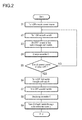
- Fig. 2 is an operational flowchart of the motor control device of Fig. 1 .
- This operational flowchart illustrates an operation of the motor control device of Fig. 1 as well as a procedure of the control method of the motor control device.
- step S1 when the electric power source 20 is turned on (step S1), the power is supplied to the seventh switch 17 from the electric power source 20, the seventh switch 17 turns on, a contact opens, and a circuit which connects the voltage regulator circuit 40, the diode 37, and the capacitor C to the fourth switch 14, the fifth switch 15, and the sixth switch 16 is broken (step S2).
- the power is supplied to the voltage regulator circuit 40 from the electric power source 20, and the power with fixed voltage is supplied to the drive circuit 30 from the voltage regulator circuit 40.
- the drive circuit 30 controls ON and OFF of the first switch 11 through the sixth switch 16 at a predetermined timing.
- the power is supplied to the coils L1 and L2 from the electric power source 20 to form a magnetic field in the motor.
- the second switch 12 and the sixth switch 16 are turned on at the same timing, and other switches of the first switch 11, the third switch 13, the fourth switch 14, and the fifth switch 15 are in OFF position, the power is supplied to the coils L2 and L3 from the electric power source 20 to form a magnetic field in the motor.
- step S3 when the first switch 11 and the sixth switch 16 are turned on at the same, other switches of the second switch 12, the third switch 13, the fourth switch 14, and the fifth switch 15 are in OFF position, the power is supplied to the coils L1 and L3 from the electric power source 20 to form a magnetic field in the motor. Controlling continuously ON and OFF of the first switch 11 through the sixth switch 16 as described above allows a rotation of the motor (step S3).
- step S4 When the power is supplied from the electric power source 20, the power is accumulated in the capacitor C from the voltage regulator circuit 40 (step S4).
- steps S2 to S5 The operation from steps S2 to S5 is repeated until the electric power source 20 is turned off, and the motor rotates the cooling fan (step S5: NO). Moreover, charge of the capacitor C is continued.
- step S5 When the electric power source 20 is turned off (step S5: YES), operations of the voltage regulator circuit 40 and the drive circuit 30 are stopped, and the first switch 11 through the sixth switch 16 are turned off.
- the first switch 11 through the sixth switch 16 When the first switch 11 through the sixth switch 16 are in OFF position, the first switch 11 through the sixth switch 16 breaks the connections between the electric power source 20 and each of coils L1, L2 and L3 (step S6).
- the seventh switch 17 When the electric power source 20 is turned off, the seventh switch 17 is turned off, the contact closes, and the seventh switch 17 forms a circuit which connects the capacitor C to the fourth switch 14, the fifth switch 15, and the sixth switch 16 (step S7).
- the capacitor C discharges to supply the power accumulated in the capacitor C to the fourth switch 14 through the diode 24, to the fifth switch 15 through the diode 26, and to the sixth switch 16 through the diode 25 (step S8).
- the fourth switch 14, the fifth switch 15, and the sixth switch 16 is turned on temporarily by the power accumulated in the capacitor C to short-circuit the coils L1, L2, and L3.
- the period, in which the fourth switch 14, the fifth switch 15, and the sixth switch 16 are in ON position depends on the power (the amount of charge) accumulated in the capacitor C.
- the motor control device and the control method of the motor control device according to the present embodiment can prevent a worker's injury even if the cooling fan does not have a finger guard, for example when the cooling fan is applied operations of hot plug.
- the seventh switch is provided which can form a circuit without power when powered off, and the capacitor with small capacity is provided which can accumulate power required for turning on the fourth switch 14, the fifth switch 15, and the sixth switch 16 in a short time. Accordingly, as described above, without supplying power to the drive circuit which applies brakes to the motor electrically, it is possible to fulfill a brake function.
Landscapes
- Engineering & Computer Science (AREA)
- Power Engineering (AREA)
- Stopping Of Electric Motors (AREA)
Applications Claiming Priority (1)
| Application Number | Priority Date | Filing Date | Title |
|---|---|---|---|
| JP2012021128A JP5923325B2 (ja) | 2012-02-02 | 2012-02-02 | モータ制御装置及びその制御方法 |
Publications (3)
| Publication Number | Publication Date |
|---|---|
| EP2624437A2 true EP2624437A2 (fr) | 2013-08-07 |
| EP2624437A3 EP2624437A3 (fr) | 2016-05-18 |
| EP2624437B1 EP2624437B1 (fr) | 2018-03-07 |
Family
ID=47561409
Family Applications (1)
| Application Number | Title | Priority Date | Filing Date |
|---|---|---|---|
| EP13151414.3A Active EP2624437B1 (fr) | 2012-02-02 | 2013-01-16 | Dispositif de commande de moteur et procédé de commande de celui-ci |
Country Status (6)
| Country | Link |
|---|---|
| US (1) | US8847525B2 (fr) |
| EP (1) | EP2624437B1 (fr) |
| JP (1) | JP5923325B2 (fr) |
| CN (1) | CN103248282B (fr) |
| PH (1) | PH12013000011A1 (fr) |
| TW (1) | TWI548201B (fr) |
Families Citing this family (10)
| Publication number | Priority date | Publication date | Assignee | Title |
|---|---|---|---|---|
| CN104753404B (zh) * | 2013-12-26 | 2018-01-30 | 台达电子工业股份有限公司 | 风扇马达刹车装置及其控制方法 |
| TWI513907B (zh) | 2013-12-26 | 2015-12-21 | Delta Electronics Inc | 風扇馬達煞車裝置及其控制方法 |
| CN103963815B (zh) * | 2014-05-20 | 2017-01-25 | 凯傲宝骊(江苏)叉车有限公司 | 电瓶无电时的紧急切换装置 |
| CN105650016B (zh) * | 2014-11-21 | 2017-11-24 | 奇鋐科技股份有限公司 | 直流风扇断电煞车之电路 |
| JP6346583B2 (ja) * | 2015-03-27 | 2018-06-20 | ミネベアミツミ株式会社 | モータ駆動制御装置およびこれを備えたファンモータシステム |
| FR3047853B1 (fr) * | 2016-02-17 | 2019-10-11 | Valeo Equipements Electriques Moteur | Systeme de commande d'un onduleur d'un moteur electrique, systeme de moteur comportant un tel systeme de commande |
| CN105805039A (zh) * | 2016-04-13 | 2016-07-27 | 江苏新安电器有限公司 | 一种变频风机刹车装置及其控制方法 |
| US10177691B2 (en) | 2016-07-06 | 2019-01-08 | Black & Decker Inc. | Electronic braking of brushless DC motor in a power tool |
| TWI614984B (zh) * | 2016-12-23 | 2018-02-11 | Asia Vital Components Co Ltd | 風扇馬達斷電自動煞車之電路 |
| US9998038B1 (en) | 2017-01-15 | 2018-06-12 | Asia Vital Components Co., Ltd. | Fan motor power-off automatic braking circuit |
Family Cites Families (14)
| Publication number | Priority date | Publication date | Assignee | Title |
|---|---|---|---|---|
| US3849714A (en) * | 1972-06-06 | 1974-11-19 | Ibm | Stepper motor control system |
| US4005348A (en) * | 1974-05-21 | 1977-01-25 | Nippondenso Co., Ltd. | Control system for DC motors |
| US4169990A (en) * | 1974-06-24 | 1979-10-02 | General Electric Company | Electronically commutated motor |
| US4218643A (en) * | 1978-12-20 | 1980-08-19 | International Business Machines Corporation | Braking system for loaded stepping motor |
| US4311948A (en) * | 1979-04-02 | 1982-01-19 | National Research Development Corporation | Dynamic braking of A.C. motors |
| US4243919A (en) * | 1980-03-31 | 1981-01-06 | The Singer Company | Motor braking arrangement |
| US6812586B2 (en) * | 2001-01-30 | 2004-11-02 | Capstone Turbine Corporation | Distributed power system |
| US6737828B2 (en) * | 2001-07-19 | 2004-05-18 | Matsushita Electric Industrial Co., Ltd. | Washing machine motor drive device |
| DE102005009341A1 (de) * | 2004-11-04 | 2006-05-18 | Diehl Ako Stiftung & Co. Kg | Schaltungsananordnung und Verfahren zur Steuerung eines Elektromotors, insbesondere einer Waschmaschine |
| US7554276B2 (en) * | 2005-09-21 | 2009-06-30 | International Rectifier Corporation | Protection circuit for permanent magnet synchronous motor in field weakening operation |
| TWI289001B (en) * | 2005-12-02 | 2007-10-21 | Delta Electronics Inc | Fan system and brake method thereof |
| JP2007259617A (ja) * | 2006-03-24 | 2007-10-04 | Japan Servo Co Ltd | 電動回転体のブレーキ装置 |
| JP5490558B2 (ja) * | 2010-02-16 | 2014-05-14 | ミネベア株式会社 | ファンモータ制御装置 |
| JP2011205746A (ja) * | 2010-03-24 | 2011-10-13 | Aisin Aw Co Ltd | 放電制御装置 |
-
2012
- 2012-02-02 JP JP2012021128A patent/JP5923325B2/ja active Active
-
2013
- 2013-01-14 PH PH12013000011A patent/PH12013000011A1/en unknown
- 2013-01-16 EP EP13151414.3A patent/EP2624437B1/fr active Active
- 2013-01-23 US US13/747,610 patent/US8847525B2/en active Active
- 2013-01-28 CN CN201310031221.0A patent/CN103248282B/zh active Active
- 2013-01-30 TW TW102103592A patent/TWI548201B/zh active
Also Published As
| Publication number | Publication date |
|---|---|
| JP2013162578A (ja) | 2013-08-19 |
| PH12013000011B1 (en) | 2014-08-04 |
| JP5923325B2 (ja) | 2016-05-24 |
| CN103248282B (zh) | 2017-04-26 |
| PH12013000011A1 (en) | 2014-08-04 |
| US20130200825A1 (en) | 2013-08-08 |
| TW201338397A (zh) | 2013-09-16 |
| EP2624437B1 (fr) | 2018-03-07 |
| EP2624437A3 (fr) | 2016-05-18 |
| TWI548201B (zh) | 2016-09-01 |
| US8847525B2 (en) | 2014-09-30 |
| CN103248282A (zh) | 2013-08-14 |
Similar Documents
| Publication | Publication Date | Title |
|---|---|---|
| US8847525B2 (en) | Motor control device and control method of the same | |
| US7781992B2 (en) | Power supply device for an electric motor method for operation of an electric motor | |
| CN111656666B (zh) | 电力转换装置 | |
| CN103296939A (zh) | 电动机驱动设备 | |
| JP2015107045A (ja) | 充放電回路およびそれを備えたモータ制御装置 | |
| JP7124716B2 (ja) | モータ駆動装置、および電動パワーステアリング装置 | |
| KR20110046324A (ko) | 엔진 시동 장치, 저항 단락 장치 | |
| KR101233958B1 (ko) | 엔진 시동 장치 | |
| JP7074074B2 (ja) | モータ駆動装置、および電動パワーステアリング装置 | |
| JP7097965B2 (ja) | 車両装置、及び、車両装置を動作させるための方法 | |
| JP6928645B2 (ja) | 電子制御装置を電圧供給部に結合するための回路装置および電子制御装置 | |
| JP4985189B2 (ja) | 電気自動車衝突安全装置 | |
| JP4799641B2 (ja) | エンジン始動装置 | |
| CN110325395B (zh) | 用于运行机动车的设备和方法,机动车 | |
| KR20150109155A (ko) | 고전압 인버터 및 이를 구비한 차량용 전동 압축기 | |
| JP2015527041A (ja) | 負荷制限時に能動型ブリッジ整流器を駆動制御するための方法、整流装置およびコンピュータプログラム製品 | |
| CN104290687A (zh) | 用于机动车的车载电网系统 | |
| JP6375977B2 (ja) | 電源装置 | |
| JP2013255297A (ja) | 車両用インバータ装置 | |
| KR102082013B1 (ko) | 전동 압축기용 인버터 장치 및 그의 구동 방법 | |
| JP6203027B2 (ja) | 永久磁石式同期モータ、電気車駆動システム、及び電気車 | |
| EP3975219B1 (fr) | Dispositif d'actionnement électromagnétique | |
| CN111771329B (zh) | 电机的驱动控制装置和电机的驱动控制方法 | |
| WO2021161797A1 (fr) | Circuit de commande de convertisseur de puissance électrique | |
| JP2011083061A (ja) | モータ制御装置 |
Legal Events
| Date | Code | Title | Description |
|---|---|---|---|
| PUAI | Public reference made under article 153(3) epc to a published international application that has entered the european phase |
Free format text: ORIGINAL CODE: 0009012 |
|
| AK | Designated contracting states |
Kind code of ref document: A2 Designated state(s): AL AT BE BG CH CY CZ DE DK EE ES FI FR GB GR HR HU IE IS IT LI LT LU LV MC MK MT NL NO PL PT RO RS SE SI SK SM TR |
|
| AX | Request for extension of the european patent |
Extension state: BA ME |
|
| PUAL | Search report despatched |
Free format text: ORIGINAL CODE: 0009013 |
|
| AK | Designated contracting states |
Kind code of ref document: A3 Designated state(s): AL AT BE BG CH CY CZ DE DK EE ES FI FR GB GR HR HU IE IS IT LI LT LU LV MC MK MT NL NO PL PT RO RS SE SI SK SM TR |
|
| AX | Request for extension of the european patent |
Extension state: BA ME |
|
| RIC1 | Information provided on ipc code assigned before grant |
Ipc: H02P 6/24 20060101ALI20160414BHEP Ipc: H02P 3/02 20060101AFI20160414BHEP Ipc: H02P 3/22 20060101ALI20160414BHEP |
|
| STAA | Information on the status of an ep patent application or granted ep patent |
Free format text: STATUS: REQUEST FOR EXAMINATION WAS MADE |
|
| 17P | Request for examination filed |
Effective date: 20161111 |
|
| RBV | Designated contracting states (corrected) |
Designated state(s): AL AT BE BG CH CY CZ DE DK EE ES FI FR GB GR HR HU IE IS IT LI LT LU LV MC MK MT NL NO PL PT RO RS SE SI SK SM TR |
|
| RIC1 | Information provided on ipc code assigned before grant |
Ipc: H02P 6/24 20060101ALI20170606BHEP Ipc: H02P 3/22 20060101ALI20170606BHEP Ipc: H02P 3/02 20060101AFI20170606BHEP |
|
| GRAP | Despatch of communication of intention to grant a patent |
Free format text: ORIGINAL CODE: EPIDOSNIGR1 |
|
| STAA | Information on the status of an ep patent application or granted ep patent |
Free format text: STATUS: GRANT OF PATENT IS INTENDED |
|
| INTG | Intention to grant announced |
Effective date: 20170720 |
|
| GRAS | Grant fee paid |
Free format text: ORIGINAL CODE: EPIDOSNIGR3 |
|
| GRAJ | Information related to disapproval of communication of intention to grant by the applicant or resumption of examination proceedings by the epo deleted |
Free format text: ORIGINAL CODE: EPIDOSDIGR1 |
|
| GRAL | Information related to payment of fee for publishing/printing deleted |
Free format text: ORIGINAL CODE: EPIDOSDIGR3 |
|
| STAA | Information on the status of an ep patent application or granted ep patent |
Free format text: STATUS: REQUEST FOR EXAMINATION WAS MADE |
|
| GRAR | Information related to intention to grant a patent recorded |
Free format text: ORIGINAL CODE: EPIDOSNIGR71 |
|
| STAA | Information on the status of an ep patent application or granted ep patent |
Free format text: STATUS: GRANT OF PATENT IS INTENDED |
|
| INTC | Intention to grant announced (deleted) | ||
| RAP1 | Party data changed (applicant data changed or rights of an application transferred) |
Owner name: SANYO DENKI CO., LTD. |
|
| RIN1 | Information on inventor provided before grant (corrected) |
Inventor name: MURAMATSU, YO Inventor name: TANIGUCHI, NORIAKI Inventor name: TODA, TAKAHISA |
|
| INTG | Intention to grant announced |
Effective date: 20171205 |
|
| GRAA | (expected) grant |
Free format text: ORIGINAL CODE: 0009210 |
|
| STAA | Information on the status of an ep patent application or granted ep patent |
Free format text: STATUS: THE PATENT HAS BEEN GRANTED |
|
| AK | Designated contracting states |
Kind code of ref document: B1 Designated state(s): AL AT BE BG CH CY CZ DE DK EE ES FI FR GB GR HR HU IE IS IT LI LT LU LV MC MK MT NL NO PL PT RO RS SE SI SK SM TR |
|
| REG | Reference to a national code |
Ref country code: GB Ref legal event code: FG4D |
|
| REG | Reference to a national code |
Ref country code: CH Ref legal event code: EP Ref country code: AT Ref legal event code: REF Ref document number: 977563 Country of ref document: AT Kind code of ref document: T Effective date: 20180315 |
|
| REG | Reference to a national code |
Ref country code: IE Ref legal event code: FG4D |
|
| REG | Reference to a national code |
Ref country code: DE Ref legal event code: R096 Ref document number: 602013033934 Country of ref document: DE |
|
| REG | Reference to a national code |
Ref country code: NL Ref legal event code: MP Effective date: 20180307 |
|
| REG | Reference to a national code |
Ref country code: LT Ref legal event code: MG4D |
|
| PG25 | Lapsed in a contracting state [announced via postgrant information from national office to epo] |
Ref country code: ES Free format text: LAPSE BECAUSE OF FAILURE TO SUBMIT A TRANSLATION OF THE DESCRIPTION OR TO PAY THE FEE WITHIN THE PRESCRIBED TIME-LIMIT Effective date: 20180307 Ref country code: HR Free format text: LAPSE BECAUSE OF FAILURE TO SUBMIT A TRANSLATION OF THE DESCRIPTION OR TO PAY THE FEE WITHIN THE PRESCRIBED TIME-LIMIT Effective date: 20180307 Ref country code: LT Free format text: LAPSE BECAUSE OF FAILURE TO SUBMIT A TRANSLATION OF THE DESCRIPTION OR TO PAY THE FEE WITHIN THE PRESCRIBED TIME-LIMIT Effective date: 20180307 Ref country code: NO Free format text: LAPSE BECAUSE OF FAILURE TO SUBMIT A TRANSLATION OF THE DESCRIPTION OR TO PAY THE FEE WITHIN THE PRESCRIBED TIME-LIMIT Effective date: 20180607 Ref country code: CY Free format text: LAPSE BECAUSE OF FAILURE TO SUBMIT A TRANSLATION OF THE DESCRIPTION OR TO PAY THE FEE WITHIN THE PRESCRIBED TIME-LIMIT Effective date: 20180307 |
|
| REG | Reference to a national code |
Ref country code: AT Ref legal event code: MK05 Ref document number: 977563 Country of ref document: AT Kind code of ref document: T Effective date: 20180307 |
|
| PG25 | Lapsed in a contracting state [announced via postgrant information from national office to epo] |
Ref country code: SE Free format text: LAPSE BECAUSE OF FAILURE TO SUBMIT A TRANSLATION OF THE DESCRIPTION OR TO PAY THE FEE WITHIN THE PRESCRIBED TIME-LIMIT Effective date: 20180307 Ref country code: LV Free format text: LAPSE BECAUSE OF FAILURE TO SUBMIT A TRANSLATION OF THE DESCRIPTION OR TO PAY THE FEE WITHIN THE PRESCRIBED TIME-LIMIT Effective date: 20180307 Ref country code: GR Free format text: LAPSE BECAUSE OF FAILURE TO SUBMIT A TRANSLATION OF THE DESCRIPTION OR TO PAY THE FEE WITHIN THE PRESCRIBED TIME-LIMIT Effective date: 20180608 Ref country code: RS Free format text: LAPSE BECAUSE OF FAILURE TO SUBMIT A TRANSLATION OF THE DESCRIPTION OR TO PAY THE FEE WITHIN THE PRESCRIBED TIME-LIMIT Effective date: 20180307 Ref country code: BG Free format text: LAPSE BECAUSE OF FAILURE TO SUBMIT A TRANSLATION OF THE DESCRIPTION OR TO PAY THE FEE WITHIN THE PRESCRIBED TIME-LIMIT Effective date: 20180607 |
|
| PG25 | Lapsed in a contracting state [announced via postgrant information from national office to epo] |
Ref country code: AL Free format text: LAPSE BECAUSE OF FAILURE TO SUBMIT A TRANSLATION OF THE DESCRIPTION OR TO PAY THE FEE WITHIN THE PRESCRIBED TIME-LIMIT Effective date: 20180307 Ref country code: EE Free format text: LAPSE BECAUSE OF FAILURE TO SUBMIT A TRANSLATION OF THE DESCRIPTION OR TO PAY THE FEE WITHIN THE PRESCRIBED TIME-LIMIT Effective date: 20180307 Ref country code: PL Free format text: LAPSE BECAUSE OF FAILURE TO SUBMIT A TRANSLATION OF THE DESCRIPTION OR TO PAY THE FEE WITHIN THE PRESCRIBED TIME-LIMIT Effective date: 20180307 Ref country code: RO Free format text: LAPSE BECAUSE OF FAILURE TO SUBMIT A TRANSLATION OF THE DESCRIPTION OR TO PAY THE FEE WITHIN THE PRESCRIBED TIME-LIMIT Effective date: 20180307 Ref country code: NL Free format text: LAPSE BECAUSE OF FAILURE TO SUBMIT A TRANSLATION OF THE DESCRIPTION OR TO PAY THE FEE WITHIN THE PRESCRIBED TIME-LIMIT Effective date: 20180307 |
|
| PG25 | Lapsed in a contracting state [announced via postgrant information from national office to epo] |
Ref country code: AT Free format text: LAPSE BECAUSE OF FAILURE TO SUBMIT A TRANSLATION OF THE DESCRIPTION OR TO PAY THE FEE WITHIN THE PRESCRIBED TIME-LIMIT Effective date: 20180307 Ref country code: SM Free format text: LAPSE BECAUSE OF FAILURE TO SUBMIT A TRANSLATION OF THE DESCRIPTION OR TO PAY THE FEE WITHIN THE PRESCRIBED TIME-LIMIT Effective date: 20180307 Ref country code: CZ Free format text: LAPSE BECAUSE OF FAILURE TO SUBMIT A TRANSLATION OF THE DESCRIPTION OR TO PAY THE FEE WITHIN THE PRESCRIBED TIME-LIMIT Effective date: 20180307 Ref country code: SK Free format text: LAPSE BECAUSE OF FAILURE TO SUBMIT A TRANSLATION OF THE DESCRIPTION OR TO PAY THE FEE WITHIN THE PRESCRIBED TIME-LIMIT Effective date: 20180307 |
|
| REG | Reference to a national code |
Ref country code: DE Ref legal event code: R097 Ref document number: 602013033934 Country of ref document: DE |
|
| PG25 | Lapsed in a contracting state [announced via postgrant information from national office to epo] |
Ref country code: PT Free format text: LAPSE BECAUSE OF FAILURE TO SUBMIT A TRANSLATION OF THE DESCRIPTION OR TO PAY THE FEE WITHIN THE PRESCRIBED TIME-LIMIT Effective date: 20180709 |
|
| PLBE | No opposition filed within time limit |
Free format text: ORIGINAL CODE: 0009261 |
|
| STAA | Information on the status of an ep patent application or granted ep patent |
Free format text: STATUS: NO OPPOSITION FILED WITHIN TIME LIMIT |
|
| PG25 | Lapsed in a contracting state [announced via postgrant information from national office to epo] |
Ref country code: DK Free format text: LAPSE BECAUSE OF FAILURE TO SUBMIT A TRANSLATION OF THE DESCRIPTION OR TO PAY THE FEE WITHIN THE PRESCRIBED TIME-LIMIT Effective date: 20180307 |
|
| 26N | No opposition filed |
Effective date: 20181210 |
|
| PG25 | Lapsed in a contracting state [announced via postgrant information from national office to epo] |
Ref country code: IT Free format text: LAPSE BECAUSE OF FAILURE TO SUBMIT A TRANSLATION OF THE DESCRIPTION OR TO PAY THE FEE WITHIN THE PRESCRIBED TIME-LIMIT Effective date: 20180307 Ref country code: SI Free format text: LAPSE BECAUSE OF FAILURE TO SUBMIT A TRANSLATION OF THE DESCRIPTION OR TO PAY THE FEE WITHIN THE PRESCRIBED TIME-LIMIT Effective date: 20180307 |
|
| PG25 | Lapsed in a contracting state [announced via postgrant information from national office to epo] |
Ref country code: MC Free format text: LAPSE BECAUSE OF FAILURE TO SUBMIT A TRANSLATION OF THE DESCRIPTION OR TO PAY THE FEE WITHIN THE PRESCRIBED TIME-LIMIT Effective date: 20180307 |
|
| REG | Reference to a national code |
Ref country code: CH Ref legal event code: PL |
|
| PG25 | Lapsed in a contracting state [announced via postgrant information from national office to epo] |
Ref country code: LU Free format text: LAPSE BECAUSE OF NON-PAYMENT OF DUE FEES Effective date: 20190116 |
|
| REG | Reference to a national code |
Ref country code: BE Ref legal event code: MM Effective date: 20190131 |
|
| REG | Reference to a national code |
Ref country code: IE Ref legal event code: MM4A |
|
| PG25 | Lapsed in a contracting state [announced via postgrant information from national office to epo] |
Ref country code: BE Free format text: LAPSE BECAUSE OF NON-PAYMENT OF DUE FEES Effective date: 20190131 |
|
| PG25 | Lapsed in a contracting state [announced via postgrant information from national office to epo] |
Ref country code: LI Free format text: LAPSE BECAUSE OF NON-PAYMENT OF DUE FEES Effective date: 20190131 Ref country code: CH Free format text: LAPSE BECAUSE OF NON-PAYMENT OF DUE FEES Effective date: 20190131 |
|
| PG25 | Lapsed in a contracting state [announced via postgrant information from national office to epo] |
Ref country code: IE Free format text: LAPSE BECAUSE OF NON-PAYMENT OF DUE FEES Effective date: 20190116 |
|
| PG25 | Lapsed in a contracting state [announced via postgrant information from national office to epo] |
Ref country code: TR Free format text: LAPSE BECAUSE OF FAILURE TO SUBMIT A TRANSLATION OF THE DESCRIPTION OR TO PAY THE FEE WITHIN THE PRESCRIBED TIME-LIMIT Effective date: 20180307 |
|
| PG25 | Lapsed in a contracting state [announced via postgrant information from national office to epo] |
Ref country code: MT Free format text: LAPSE BECAUSE OF NON-PAYMENT OF DUE FEES Effective date: 20190116 |
|
| REG | Reference to a national code |
Ref country code: DE Ref legal event code: R082 Ref document number: 602013033934 Country of ref document: DE Representative=s name: HL KEMPNER PATENTANWAELTE, SOLICITORS (ENGLAND, DE Ref country code: DE Ref legal event code: R082 Ref document number: 602013033934 Country of ref document: DE Representative=s name: HL KEMPNER PATENTANWALT, RECHTSANWALT, SOLICIT, DE Ref country code: DE Ref legal event code: R082 Ref document number: 602013033934 Country of ref document: DE Representative=s name: HL KEMPNER PARTG MBB, DE |
|
| PG25 | Lapsed in a contracting state [announced via postgrant information from national office to epo] |
Ref country code: IS Free format text: LAPSE BECAUSE OF FAILURE TO SUBMIT A TRANSLATION OF THE DESCRIPTION OR TO PAY THE FEE WITHIN THE PRESCRIBED TIME-LIMIT Effective date: 20180707 |
|
| PG25 | Lapsed in a contracting state [announced via postgrant information from national office to epo] |
Ref country code: HU Free format text: LAPSE BECAUSE OF FAILURE TO SUBMIT A TRANSLATION OF THE DESCRIPTION OR TO PAY THE FEE WITHIN THE PRESCRIBED TIME-LIMIT; INVALID AB INITIO Effective date: 20130116 |
|
| PG25 | Lapsed in a contracting state [announced via postgrant information from national office to epo] |
Ref country code: MK Free format text: LAPSE BECAUSE OF FAILURE TO SUBMIT A TRANSLATION OF THE DESCRIPTION OR TO PAY THE FEE WITHIN THE PRESCRIBED TIME-LIMIT Effective date: 20180307 |
|
| PGFP | Annual fee paid to national office [announced via postgrant information from national office to epo] |
Ref country code: GB Payment date: 20260123 Year of fee payment: 14 |
|
| PGFP | Annual fee paid to national office [announced via postgrant information from national office to epo] |
Ref country code: DE Payment date: 20260121 Year of fee payment: 14 |
|
| PGFP | Annual fee paid to national office [announced via postgrant information from national office to epo] |
Ref country code: FI Payment date: 20260129 Year of fee payment: 14 |
|
| PGFP | Annual fee paid to national office [announced via postgrant information from national office to epo] |
Ref country code: FR Payment date: 20260123 Year of fee payment: 14 |