EP2624748B1 - Vorrichtung zur verwendung in der electrobiologischen signalmessung in gegenwart eines magnetfeldes - Google Patents
Vorrichtung zur verwendung in der electrobiologischen signalmessung in gegenwart eines magnetfeldes Download PDFInfo
- Publication number
- EP2624748B1 EP2624748B1 EP11782479.7A EP11782479A EP2624748B1 EP 2624748 B1 EP2624748 B1 EP 2624748B1 EP 11782479 A EP11782479 A EP 11782479A EP 2624748 B1 EP2624748 B1 EP 2624748B1
- Authority
- EP
- European Patent Office
- Prior art keywords
- eeg
- electrodes
- group
- sampling lines
- magnetic field
- Prior art date
- Legal status (The legal status is an assumption and is not a legal conclusion. Google has not performed a legal analysis and makes no representation as to the accuracy of the status listed.)
- Active
Links
Images











Classifications
-
- A—HUMAN NECESSITIES
- A61—MEDICAL OR VETERINARY SCIENCE; HYGIENE
- A61B—DIAGNOSIS; SURGERY; IDENTIFICATION
- A61B5/00—Measuring for diagnostic purposes; Identification of persons
- A61B5/0048—Detecting, measuring or recording by applying mechanical forces or stimuli
- A61B5/0055—Detecting, measuring or recording by applying mechanical forces or stimuli by applying suction
-
- A—HUMAN NECESSITIES
- A61—MEDICAL OR VETERINARY SCIENCE; HYGIENE
- A61B—DIAGNOSIS; SURGERY; IDENTIFICATION
- A61B5/00—Measuring for diagnostic purposes; Identification of persons
- A61B5/24—Detecting, measuring or recording bioelectric or biomagnetic signals of the body or parts thereof
- A61B5/25—Bioelectric electrodes therefor
- A61B5/279—Bioelectric electrodes therefor specially adapted for particular uses
- A61B5/291—Bioelectric electrodes therefor specially adapted for particular uses for electroencephalography [EEG]
-
- A—HUMAN NECESSITIES
- A61—MEDICAL OR VETERINARY SCIENCE; HYGIENE
- A61B—DIAGNOSIS; SURGERY; IDENTIFICATION
- A61B5/00—Measuring for diagnostic purposes; Identification of persons
- A61B5/24—Detecting, measuring or recording bioelectric or biomagnetic signals of the body or parts thereof
- A61B5/316—Modalities, i.e. specific diagnostic methods
- A61B5/369—Electroencephalography [EEG]
- A61B5/372—Analysis of electroencephalograms
-
- A—HUMAN NECESSITIES
- A61—MEDICAL OR VETERINARY SCIENCE; HYGIENE
- A61B—DIAGNOSIS; SURGERY; IDENTIFICATION
- A61B2562/00—Details of sensors; Constructional details of sensor housings or probes; Accessories for sensors
- A61B2562/22—Arrangements of medical sensors with cables or leads; Connectors or couplings specifically adapted for medical sensors
- A61B2562/221—Arrangements of sensors with cables or leads, e.g. cable harnesses
- A61B2562/222—Electrical cables or leads therefor, e.g. coaxial cables or ribbon cables
Definitions
- the present invention is in the field of medical devices, and relates to a device for use in combined measurements/monitoring of electro-biological signals in presence of a magnetic field.
- some embodiments of the present invention relate to, but are not restricted to, electroencephalogram (EEG) during magnetic resonance imaging (MRI), particularly functional MRI (fMRI), or during Transcranial Magnetic Stimulation (TMS).
- EEG electroencephalogram
- MRI magnetic resonance imaging
- fMRI functional MRI
- TMS Transcranial Magnetic Stimulation
- EEG technique involves measurements of electrical signals generated by the brain's neurons, via a multitude of electrodes placed on a patient's scalp.
- the neural signals are transmitted by wires to an EEG monitoring system that records the neural signals, and generates data about the signal variation in time, which data can be further analyzed and possibly also displayed.
- EEG enables high temporal resolution, in the order of milliseconds, and is therefore useful for detecting quick changes in the electrical activity of the brain.
- EEG has an undesirably low spatial resolution.
- MRI is a noninvasive medical imaging technique used in radiology to visualize detailed internal structures and limited functions of the body.
- a magnetic field is used to align the nuclear magnetization of predetermined materials in the fluids of a body.
- Radio frequency (RF) fields are used to systematically alter the alignment of this magnetization. This causes the materials to produce a rotating magnetic field detectable by a scanner. This signal can be manipulated/affected by additional magnetic fields to build up enough information to construct an image of the body.
- RF radio frequency
- This signal can be manipulated/affected by additional magnetic fields to build up enough information to construct an image of the body.
- Different types of MRI generally used for brain scans are, for example, fMRI and magnetic resonance spectroscopy (MRS).
- fMRI technique has been used since the 1990s to study the hemodynamic response (change in blood flow) related to neural activity in the brain.
- levels of deoxyhemoglobin in the brain are detected.
- Deoxyhemoglobin levels change in areas of the brain in response to changes in neural activity of the specific areas.
- deoxyhemoglobin is paramagnetic, when a patient's brain is subjected to a high magnetic field, deoxyhemoglobin aligns with the magnetic field. Radio frequency fields are then applied to the patient's brain, to rotate the aligned deoxyhemoglobin.
- fMRI is characterized by the high spatial resolution of measurements, as different levels of deoxyhemoglobin in specific regions of the brain indicate different levels of neural activity in those specific regions.
- fMRI is, however, characterized by relatively low temporal resolution, as blood flow response to neural activity peaks approximately 5 seconds after the firing of the neurons.
- MRS technique utilizes the principles of MRI and focuses on receiving rotating magnetic fields produced by nuclei such as hydrogen, phosphorus, carbon, sodium, and fluorine, in order to detect biochemical materials of interest, such as, for example, choline containing compounds, creatine, inositol, glucose, N-acetyl aspartate, alanine, and lactate. Elevated concentrations of some of these biochemical materials may indicate the presence of a number of brain diseases, for example cancer, epilepsy, Alzheimer's Disease, Parkinson's disease, and Huntington's Chorea.
- nuclei such as hydrogen, phosphorus, carbon, sodium, and fluorine
- biochemical materials of interest such as, for example, choline containing compounds, creatine, inositol, glucose, N-acetyl aspartate, alanine, and lactate. Elevated concentrations of some of these biochemical materials may indicate the presence of a number of brain diseases, for example cancer, epilepsy, Alzheimer's Disease, Parkinson
- EEG and fMRI scans may be performed in simultaneously with EEG measurements. This may be done, for example, for the purpose of saving time.
- EEG/fMRI otherwise known as EEG/fMRI
- EEG/fMRI the combination of EEG and fMRI scans, otherwise known as EEG/fMRI, however has brought about new problems associated with the fact that EEG measurements are affected by noise artifacts, when performed in the presence of a magnetic field. Therefore, noise artifacts have appeared in EEG measurements performed in conjunction with fMRI scans.
- MRS measurements simultaneously with EEG measurements EEG scans are also affected by noise artifacts caused by the presence of a magnetic field.
- Noise can also be introduced into the EEG signals during EEG recording within an MRI scanner.
- noise may be introduced by motion within the MRI environment during the recording of the EEG signals. This type of noise is called a motion artifact.
- Motion artifacts may be, for example, associated with a ballistocardiogram motion, and/or a movement of the patient during the EEG recording, and/or a movement of EEG equipment during the recording.
- the amplitude of the noise may be approximately of the same magnitude as the EEG signal.
- Some motion artifacts are present as a direct result of electromagnetic induction in the magnetic field.
- EEG scans as motion causes EEG wires to move within the MRI scanner's magnetic field, the size of the loops created by two wires connected to the electrodes varies, affecting the magnetic flux through the loops, and therefore introducing an induced current through the loops.
- TMS Transcranial Magnetic Stimulation
- rTMS repetitive transcranial magnetic stimulation
- EEG recordings performed during TMS may be affected by a motion artifact, as explained above.
- Further noise affecting EEG measurements in a TMS environment includes a gradient artifact produced by interference in the electrical loops due to the changes in the magnetic field.
- This gradient artifact present in EEG measurements during TMS is also known as a magnetic pulse artifact. More specifically, the alternating magnetic field affects magnetic flux through the loops and induces currents, thus creating a gradient artifact in the EEG measurements.
- wires are tightly held together in bundles essentially parallel to each other.
- the wires may be twisted together to form the bundles.
- a size of loops formed by wires belonging to the same bundle is decreased, thereby decreasing the motion artifact in EEG readings.
- Reduction of the loop size also reduces current induced by an alternating magnetic field. This approach enables bipolar EEG measurements with a decreased presence of motion artifacts and/or gradient artifacts.
- the methods, systems and arrangements include a cap made of conductive inks with sensor positions for attaching a plurality of sensors to the patient's head.
- the sensors can include electrodes as well as motion sensors for improving EEG signal quality and MRI image quality in the presence of motion noise and other artifacts within the MRI environment.
- the electrodes may be composed of conductive inks, and can be used in high magnetic fields due to a weak interaction with the RF fields generated by the fMRI scanner.
- Motion artifacts may generally be classified into two categories: Balisto-Cardio-Gram (BCG) and Non-Balisto-Cardio-Gram (NBCG).
- BCG artifacts are related to scalp pulsation and head movements caused by heart beats.
- NBCG artifacts are generated by movements that are unrelated to heart beats.
- Several techniques have been proposed for suppression of BCG artifacts.
- One such technique is based on subtraction of averaged BCG artifacts from the EEG data after the calculation of averaged template from subsequent BCG artifacts ( Allen P.J, Polizzi G, Krakow K et al, 1998, Identification of EEG events in the MRI scanner: the problem of pulse artifact and method for its subtraction.
- EEG wires are held together or twisted together in bundles to decrease the size of electric current loops formed in wires belonging to the same bundle, thereby decreasing the motion artifact in EEG readings.
- This approach enables to decrease the motion artifacts and/or gradient artifacts only as long as the measurements are taken between two wires belonging to the same bundle.
- the present invention as defined in the independent claims 1, 6 and 14 and provides a novel technique for taking EEG measurements in the presence of a magnetic field, and for processing/interpreting the EEG measured data.
- the present invention provides a novel device for use in EEG measurements/monitoring in presence of a magnetic field (constant or changing), enabling more precise profiling/mapping of the EEG data.
- the invention enables the detection of neural signals from locations extending along intersecting axes, and thus allows for the precise determination of the neural signal vector for each location. This significantly improves the interpretation of measurements and also further contributes to reduction of motion and/or gradient artifacts.
- the wiring array is a net structure formed by the crossing of two groups of sampling lines. In each group at least one of the sampling lines includes at least some bundle of wires tightly held together.
- the sampling lines of the same group are arranged in a spaced-apart substantially parallel relationship along one axis, and those of the other group are arranged in a spaced-apart substantially parallel relationship along a second intersecting axis.
- Such a wiring array enables the EEG monitor device to read EEG data from electrodes connected to wires belonging to the same bundle. In this manner, EEG measurements may be performed along either direction defined by the bundles belonging to crossing sampling lines, while decreasing an effect of the motion and/or gradient artifact, produced by the magnetic field produced, for example by MRI or TMS, in the EEG measurements.
- the present invention provides a novel technique for recognizing and suppressing motion artifacts during EEG measurements, by using a wiring array connecting an EEG electrode arrangement to an EEG monitor.
- the wiring array includes different sampling lines. At least one of the sampling lines includes a bundle of wires tightly held together extending along a first axis.
- each of the remaining sampling lines is constituted by a single wire, and extends parallel to a second axis.
- the sampling lines (bundles and, if present, single wires) may be parallel, non-parallel, or crossing to form a net array.
- the invention provides an optimal selection of the EEG electrode combinations for measurements.
- a first set of bipolar EEG measurements is made between electrodes connected to wires of the same bundle; a second set of bipolar EEG measurements is made between electrodes connected to wires belonging to different sampling lines (which are preferably, but not necessarily intersecting sampling lines).
- Each of the neural signals measured between electrodes, both along bundles and across bundles sampling lines, is transmitted to a different channel/utility of the EEG monitor, where data indicative of each signal is generated. In this manner, both sets of measurements may be performed simultaneously.
- a separation algorithm (ICA, PCA, for example) is applied to the measured data to obtain components of the measured data which are differently distributed between the channels. Since the effect of motion artifacts is larger in data corresponding to measurements between electrodes connected to different sampling lines, a value indicative of the interference signal (such as voltage or current, for example) is larger in the EEG data generated by the second measurements set, because such value is increased by the artifact.
- the components of the data generated by the second measurement set which spot a value that is consistently higher than the value of the corresponding components of the data generated by the first measurement set, correspond to the artifact-affected channels. The removal of such artifact-affected components from all channels will remove interference in data generated by both the first and second measurement sets. Thus, by using simultaneous measurements along and across bundles, motion artifacts can be estimated and suppressed.
- Another aspect of the present invention relates to a different technique for recognizing artifacts.
- This second technique may be used independently of the first technique described above, or in conjunction with it in order to increase its discriminative power.
- This second technique relies on the fact a source of electric field inside a patient's head produces electric potentials (neural signals) that are distributed between EEG electrodes according to the electrodes' positions on the scalp.
- signals which are induced by movements of the head and EEG cables inside the magnetic field (motion artifacts) or induced by a changing magnetic field (gradient artifacts) are dependent on the whole electric circuit (loop) configuration (head and wires) and not only on EEG electrode locations on the scalp.
- This feature can be used to separate neural signals from artifacts generated by the presence of the magnetic field in the following manner: when the source of the signal is inside the head, and at least three electrodes (A, B, C) are provided in the measurement system, the vector sum of the signal's gradients along the lines AB and BC is a vector along the line AC. Conversely, when the measured signal is an artifact (induced by movement of EEG electrode cables and/or of an EEG amplifier inside a magnetic field and/or by a changing magnetic field), the signal's gradient along the line AC is not predictable by vector sum of the signal's gradients along the lines AB and BC, and would most probably be different.
- At least some of the measured signals include a neural component generated by a source within the brain and an artifact component. Therefore, a separation algorithm (ICA, PCA, for example) is applied to the measured signals to obtain components of the measured signals. Then gradients of each component along the sides of the triangle or (parameters that are proportional to such gradients, such as weights) are determined. This may be done by selecting three weights for each component, such that each weight corresponds to a bipolar measurement along one of the sides of a triangle formed by the arrangement of the three selected electrodes.
- ICA separation algorithm
- the respective signal component is classified as a neural component originating from the brain. Otherwise, the component is classified as an artifact and rejected.
- an aspect of some embodiments of the present invention relates to a measurement device, as defined in Claim 1, for use in an EEG measurement performed in the presence of a magnetic field, the device comprising a wiring array for connecting an electrodes arrangement to an electroencephalogram (EEG) monitoring device.
- the wiring array comprises a plurality of sampling lines arranged to form a first group of sampling lines and a second group of sampling lines.
- the sampling lines of the first group are arranged in a spaced-apart substantially parallel relationship extending along a first axis, at least some of such sampling lines being wire bundles of said first group.
- the sampling lines of the second group are arranged in a spaced-apart substantially parallel relationship extending along a second axis, intersecting with said first axis, such that said second group of bundles crosses said first group of bundles to form a net structure.
- Each of the bundles of the first group comprises a plurality of first wires for connecting to a corresponding first plurality of electrodes of said EEG electrodes arrangement.
- Each of the bundles of the second group comprises a plurality of second wires for connecting to a corresponding second plurality of electrodes of said EEG electrodes arrangement.
- the wiring array is configured and operable for transmitting a signal measured by the respective electrodes to the EEG monitoring device, enabling the generation of EEG data indicative of the neural signal profile along two directions and characterized by reduced motion artifact and/or reduced gradient artifact associated with the presence of the magnetic field during the EEG measurement.
- FIG. 6 Another aspect of the present invention relates to a net structure as defined in Claim 6 and configured for being placed on a patient's scalp in an EEG measurement performed in the presence of a magnetic field, the net structure comprising a wiring arrangement, which comprises first and second groups of sampling lines including wire bundles and extending along first and second intersecting axes respectively, each group being formed by a plurality of spaced-apart substantially parallel sampling lines transmitting EEG signals from a respective plurality of spaced-apart EEG measurement locations, thereby enabling to read EEG data from the measurement locations via the first and second groups of sampling lines, while decreasing at least one of a motion artifact and a gradient artifact generated in the EEG measurement.
- a wiring arrangement which comprises first and second groups of sampling lines including wire bundles and extending along first and second intersecting axes respectively, each group being formed by a plurality of spaced-apart substantially parallel sampling lines transmitting EEG signals from a respective plurality of spaced-apart EEG measurement locations, thereby enabling
- the present invention is in the field of medical devices, and relates to a device for use in combined measurements/monitoring of electro-biological signal in the presence of a magnetic field.
- some embodiments of the present invention relate to, but are not restricted to, electroencephalogram (EEG) during magnetic resonance imaging (MRI), particularly functional MRI (fMRI), or during Transcranial Magnetic Stimulation (TMS).
- EEG electroencephalogram
- MRI magnetic resonance imaging
- fMRI functional MRI
- TMS Transcranial Magnetic Stimulation
- the device of the present invention includes a novel configuration of a wiring array for connecting a bipolar electrodes' arrangement to an EEG monitoring device, for use in EEG scans performed in the presence of a magnetic field.
- the wiring array may be used, for example, in simultaneous EEG and MRI (particularly EEG and fMRI) scans, and in EEG scans during TMS.
- the wiring array includes two groups of wire bundles extending along two intersecting lines (axes), and crossing each other to form a net structure. It should be understood that for the purposes of this patent application the term "line” or "axis” should not be limited to a straight line, but rather should be interpreted broadly to cover a curve extending along a curved surface.
- Each group of bundles includes an arrangement of spaced-apart wire bundles.
- Each wire bundle includes a plurality of wires held tightly together (or twisted together) for connecting to a plurality of EEG electrodes. Because the wires of each bundle are held tightly together (or twisted together), the size of loops of electric current created by two wires of the same bundle, when connected to two electrodes, is decreased.
- the wiring array of such two groups of wire bundles enables EEG measurements with a decreased effect from motion and/or gradient artifacts to be performed along two directions defined by the two groups of wire bundles.
- the first and second groups of wire bundles are preferably substantially perpendicular to each other, i.e. extend along the first and second substantially perpendicular axes respectively. Neural electrical activity of any orientation will have a considerable gradient along the direction of at least one of the perpendicular bundles, and is therefore easily and precisely detectable. Even when the direction of the neural signal forms a 45-degree angle with each of the bundles, each bundle picks up a signal attenuated by only a factor of 1 / 2 , about equal to 0.71.
- the wiring array of the present invention can thus advantageously be used with a plurality of electrodes arranged with high density, for example, when 64 or more electrodes are used in an EEG scan. In such a case, the wiring array enables an accurate mapping (reconstruction of amplitude and orientation) of any neural signal by simple trigonometric computations.
- the wiring array of the present invention provides for reducing the motion and/or gradient artifact in EEG readings before such readings are processed and/or combined with a signal generated by an external sensor, such as a motion detector. In this manner, the accuracy of data obtained by the processing and/or combination of EEG readings with a signal generated by the external sensor is increased. In a variant, the need for the use of the external sensor is obviated altogether. In a similar fashion, owing to the fact that the motion and/or gradient artifact in the EEG readings is reduced by the presence of the two-dimensional wiring array, a need for suppressing the motion and/or gradient artifacts by complicated processing of the EEG signals is diminished, and in some cases even obviated.
- the wiring array of the present invention may be placed directly on a patient's scalp, or may be part of (integral with) an EEG cap designed to be worn by the patient.
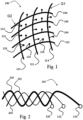
- Fig. 1 there is schematically exemplified a part of the device of the present invention including a portion of a wiring array 100.
- the wiring array 100 is designed for connecting an electrodes' arrangement to an EEG monitoring device for use in concurrent EEG measurements in the presence of a magnetic field, such as the magnetic field generated in MRI (and fMRI) scans or in TMS.
- the wiring array 100 includes a plurality of sampling lines which in the present examples are constituted by wire bundles, and includes two groups G1 and G2 of such wire bundles. Each group includes a plurality of wire bundles arranged in a spaced apart and substantially parallel fashion. As shown in the present example, the first group G1 includes wire bundles 102, 104, 106, and 108, and the second group G2 includes wire bundles 110, 112, and 114. It should be understood, although not specifically shown here, that each wire bundle includes wires that are tightly held together, or optionally twisted together. This is described more specifically below with reference to Fig. 2 .
- the wire bundles are designed for connecting respective EEG electrodes to an EEG monitoring device.
- the wire bundle 102 includes wires for connecting electrodes 116 and 118 to the EEG monitoring device (not shown).
- the wire bundle 110 includes wires for connecting electrodes 120, 122, and 124 to the EEG monitoring device.
- Bipolar EEG measurements may be taken between any two electrodes connected to wires belonging to the same wire bundle, for example between electrodes 116 and 118, or between electrodes 120 and 124.
- measurements taken between electrodes connected to wires of the same bundle are characterized by a reduced motion and/or gradient artifact because the wires are tightly held together and the size of the electric current loops between the pairs of electrodes is reduced.
- the bipolar EEG measurements are taken between pairs of adjacent electrodes, such as electrodes 120 and 122, or the electrodes 122 and 124.
- Bipolar EEG measurements taken between non adjacent pairs may be affected by motion and/or gradient artifacts, because the loop size defined by wires connecting the non-adjacent electrode pairs is larger than the loop size defined by wires connecting adjacent electrode pairs.
- the measurement between non adjacent electrode pairs connected to the same bundle may still be characterized by a lower artifact effect compared to measurement without the proposed bundles.
- the EEG recording is referential, and is used to produce a virtual bipolar signal.
- a first signal is measured between a reference electrode and a first electrode
- a second signal is measured between the reference electrode and a second electrode.
- the first and second signals are combined to yield a combination signal indicative of a signal that would have been yielded if the measurement had been performed between the first and second electrodes. This is generally done by subtracting the first signal from the second signal (or vice versa ) .
- This process is called virtual bipolar montage.
- the first and second electrodes are connected to wires of the same bundle, artifacts of similar amplitudes are present in the first signal and second signal. The subtraction described above, therefore, produces a decreased artifact in a combined signal.
- the wire array 100 enables EEG measurements characterized by decreased motion and/or gradient artifacts to be performed along two axes, along which the first and second groups' wire bundles extend.
- the axis is not necessarily straight and is practically not when the wiring array is configured for placement on a patient's scalp, but the projection of wire bundles' of the same group onto the same plane would result in substantially parallel straight lines extending along the common axis.
- the first and second axes of the arrangement of respectively the first group of wire bundles and the second group of wire bundles are perpendicular to each other.
- the neural electrical activity of any orientation will necessarily have a considerable gradient along the direction of at least one of the perpendicular bundles, and is therefore easily detectable.
- the use of such a two-dimensional wiring array is also advantageous when a high density of electrodes is present, which is preferred to increase the spatial resolution of measurements.
- the wiring array is manufactured according to specific measurements, for connecting the EEG monitoring device to the EEG electrodes positioned along a patient's scalp according to a desired configuration, such as any International System, for example the International 10-20 system.
- a desired configuration such as any International System, for example the International 10-20 system.
- at least some of the wires of the array are designed for being removably connectable to the respective electrodes. In this manner electrodes may be replaced between scans. This is advantageous when an electrode turns defective, and also allows the wiring array to be used a plurality of times. Also, this enables the electrodes' set, which when in use is to be in contact with the patient's scalp, to be disposable.
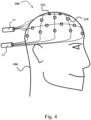
- Fig. 2 shows more specifically an exemplary bundle 110 of wires connected to a plurality of EEG electrodes.
- the wire bundle 110 includes a plurality of wires of different lengths, for connecting the same EEG monitoring device to a plurality of electrodes at different locations on the scalp.
- the wires 202, 204 and 206 are held tightly together, in order to decrease the size of loops formed between the wires, and are electrically isolated from each other. In a preferred embodiment, the wires are held tightly together by being twisted together.
- the wires 202, 204 and 206 exit the bundle 110 at different locations along the bundle to connect to electrode 120, 122 and 124 respectively.
- Figs 3a and 3b show the principles of mapping/profiling (determination of the amplitude and direction) of a neural signal generated by EEG measurements performed using the wiring array of the present invention (e.g. that of Fig. 1 ).
- Fig. 3a corresponds to a specific example when an angle between crossing wire bundles is 90 degrees (perpendicular first and second axes)
- Fig. 3b corresponds to more general situation for any angle ⁇ between crossing wire bundles (i.e. intersecting first and second axes).
- a neural signal having an amplitude c and an orientation (direction) ⁇ with respect to a longitudinal axis is produced in a patient's brain.
- the neural signal has a first gradient having an amplitude A along the longitudinal axis, for example the axis defined by the wires' group G2, and a second gradient having an amplitude b along a transverse axis, for example the axis defined by the group G1 .
- the amplitude a is detected by a bipolar (real or virtual) measurement between two electrodes connected to one of the bundles of group G2, for example, electrodes 116 and 118.
- the amplitude b is detected by a bipolar (real or virtual) measurement between two electrodes connected to one of the bundles of group G1 and proximal to the electrodes 116 and 118, for example electrodes 120 and 122.
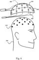
- FIG. 4 showing schematically a net structure 300 formed by the above-described wiring array 100 and designed for being placed on a patient's scalp during an EEG scan performed in the presence of a magnetic field, and for leading EEG signals from electrodes to an EEG monitoring device.
- the net structure 300 is thus formed by two intersecting groups G1 and G2 of spaced-apart wire bundles.
- the net structure 300 connects an EEG monitoring device (not shown) to a plurality of EEG electrodes (such as electrodes 122 and 118, for example) located at predetermined measurement locations on the scalp of patient 306.
- the net structure 300 is rigid or semi-rigid, in order to on the one hand maintain a desired shape, and on the other hand to enable the net structure 300 to fit the scalp of patient 306.
- the net structure 300 is flexible and assumes the desired shape only when the net structure is worn by the patient 306.
- the net structure 300 may be removably connectable to the electrodes, or alternatively may be integral to the electrodes.
- the net structure 300 is connectable to various kinds of electrodes, such as non-invasive electrodes pasted on the scalp, to intracranial electrodes (e.g. a subdural electrodes grid), or to semi-invasive (e.g. epidural peg electrodes). Any type of scalp EEG electrodes or intracranial or semi-invasive electrodes may be included in the electrode array, and the wires related to such electrodes can be organized in bundles corresponding to intersecting sampling lines to form the net array 300.
- FIG. 5 an example is illustrated of a possible setup of the net structure of a wiring array of Fig. 4
- the groups G1 and G2 are divided into sub-groups G1a and G1b , and G2a and G2b, respectively. It should be understood that there may be any number of sub-groups for each group, and not necessarily the same number for both groups. Sub-groups belonging to the same group are separated by a relatively large distance. Furthermore, adjacent bundles belonging to the same group belong to different subgroups. In other words, the sampling lines of different sub-groups of the same group are arranged in an alternating fashion. For example, bundles 102 and 104 are adjacent bundles belonging to the same group G2. However, bundle 102 belongs to subgroup G2a, while bundle 104 belongs to subgroup G2b.
- first bundle holder 310 which firmly holds subgroups G1a and G1b at a desired distance from each other.
- the separation between subgroups G2a and G2b is implemented via a second bundle holder 312.
- the bundle holders 310 and 312 are preferably chosen to be non-magnetic, so that their presence neither generates a further magnetic field nor is affected by the magnetic field in order not to affect measurements between electrodes.
- the above-described setup of the net structure 300 ensures that while the electromagnetic induction loops/circuits formed by wires in the same bundle are small, the electromagnetic induction loops formed by wires in the adjacent bundle are relatively large.
- Such a feature may be advantageous when the net structure 300 is used in the measurement of an EEG signal, and the EEG signal is analyzed/processed via an artifact recognition/suppression technique which relies on the fact that artifacts in measurements performed between electrodes that belong to different bundles (i.e. measurement across bundles) are typically larger than artifacts in measurements performed between electrodes in the same bundles (i.e. measurement along bundles).
- the artifacts in measurements across the bundles are increased, while the artifacts in measurements along the bundles are left unchanged.
- a relation between measurements across the bundles and measurements along the bundles is significantly greater when an artifact is present, and therefore the chance of identifying artifacts via the above artifact recognition/suppression technique is increased.
- Examples of the above artifact recognition/suppression technique include a virtual-motion-sensor (VMS) technique (described in detail in Fig. 9 ) and an estimated-versus-measured (EVM) technique (described in detail in Fig. 10 ).
- sampling lines i.e. division into alternatingly arranged sub-groups of sampling lines
- all the sampling lines be wire bundles. It would generally be sufficient if only some of the sampling lines are constituted by the wire bundle.
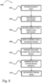
- Fig. 6 is a schematic drawing illustrating a cap 400 designed for being worn by a patient during an EEG scan performed in the presence of a magnetic field.
- the cap 400 includes a wiring array, such as the wiring array 100 described in Fig. 1 above, configured for leading EEG signals from a plurality of electrodes (such as electrode 120) located on the patient's scalp to an EEG monitoring device.
- the cap 400 is configured for being worn by patient 306, in a manner that enables the wiring array incorporated in the cap to connect an EEG monitoring device to a plurality of electrodes located on the patient's scalp.
- the electrodes are placed on the patient's scalp separately from the cap, and the cap 400 with the wiring array when worn by the patient 306, allows for connecting the wiring array of the cap 400 to the electrodes.
- the cap 400 may include an electrically nonconductive headpiece 406, which sports an inner surface designed for being fitted to the patient's head and an outer surface designed for connecting the wiring array to said headpiece 406.
- the latter further includes a plurality of apertures, generally 408, for being traversed by a portion of the EEG electrodes for connecting to the wires of the wiring array.
- the wiring array may be glued to the outer surface of the cap 400, or secured to the cap 400, for example via fasteners located on the outer surface of the cap 400.
- the electrodes are initially connected to the wiring array of the cap 400 (e.g. are integral with the wiring array or connectable thereto), and the entire system formed by the cap 400 carrying the wiring array and the electrodes is put on the patient's scalp for measurements.
- the cap 400 is made of a stretchable material and carries a sufficiently flexible net of the wiring array, for closely fitting the scalp of the patient. This improves the securing of the cap 400 to the patient's scalp and limits the movement of the cap 400 with respect to the patient. In this manner, motion artifacts generated by a motion of the cap 400 independent of the patient are reduced.
- Fig. 7 is a schematic drawing illustrating a system 500 for simultaneous EEG and MRI scans, using a wiring array of the present invention.
- the system 500 includes an MRI scanner 502 for imaging the patient's brain, an EEG monitoring device 504, a plurality of EEG electrodes, generally at E, designed for being placed at predetermined locations on the scalp of a patient 306 and for detecting neural signal signals, and a wiring array 100, as described above in reference to Fig. 1 , for relaying the neural signals to the EEG monitoring device 504 for analyzing the signals and generating EEG data.
- the MRI scanner 502 may be, for example, an fMRI scanner.
- the EEG data taken simultaneously with MRI scans is affected by a decreased presence of motion artifacts, due to the presence of the wiring array 100, as explained above. Furthermore, due to the net structure of the wiring array, the neural signals are detected along two directions, facilitating neural signal detection and interpretation with high precision.
- the provision of the two-dimensional wiring array enables the EEG monitoring device to perform an accurate reconstruction of any neural signal vector (amplitude and orientation of any neural signal) by simple trigonometric computations, as explained above.
- the wiring array is applied to patient 306 either directly, as described with reference to the net structure 300 of Fig. 4 , or by using a cap, as described above, with reference to Fig. 6 .
- a TMS coil device is present, to generate a changing (optionally fluctuating) magnetic field.
- the signal to noise ratio of the EEG measurements during TMS due to eliminating or at least significantly reducing a contribution of motion related as well as gradient-artifact related components in the measured signal) and the interpretation of the measured EEG data are improved due to the use of the wiring array 100, as explained above.
- FIG. 8 a flowchart 600 is shown illustrating a method for performing an EEG measurement in the presence of a magnetic field.
- a magnetic field is provided (step 602) and EEG electrodes joined to a patient's scalp are provided (step 604).
- the magnetic field may be constant or varying, such as a magnetic field provided by an operation of an MRI scanner (for example a fMRI or MRS scanner); the magnetic field may be varying (or fluctuating), such as the magnetic field provided by a TMS coil device.
- the electrodes may be disposed in a desired configuration, for example according to the International 10-20 system.
- a wiring array (or net structure) is placed on the patient's scalp for connecting the EEG electrodes to an EEG monitoring device.
- the wiring array can be placed in a separate step (step 606) or together with the placement of electrodes in case the wiring array and the electrodes are initially configured into an integral device.
- the wiring array is generally similar to an array as described in Fig. 1 , and may be placed upon a patient's scalp either directly, as shown in Fig. 4 , or with the aid of a cap, as shown in Fig. 6
- a signal is measured by the electrodes.
- the measurement may be bipolar or referential, as explained above in the description of Fig. 1 . If a bipolar measurement is performed between two electrodes connected to the same bundle, the measurement is affected by a decreased motion and/or gradient artifact, as explained above. If a referential measurement is performed, virtual bipolar montage is performed (usually in the EEG monitor) to yield EEG data indicative of the neural signal between electrode pairs belonging to the same bundle, such that the EEG data is affected by a decreased motion and/or gradient artifact.
- the EEG measurement is transmitted via the wiring array to an EEG monitoring device, and EEG data is generated (step 612).
- the EEG data can be processed in order to reconstruct the amplitude and orientation of the detected neural signal (step 614).
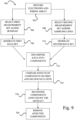
- FIG. 9 there is shown a flowchart 700 exemplifying a method of the invention for recognizing and suppressing an artifact (e.g. motion artifact and/or a gradient artifact) generated in an EEG measurement in the presence of a magnetic field.
- an artifact e.g. motion artifact and/or a gradient artifact
- this method provides for effective EEG measurement using either one of the wiring arrays of Figs 1 , 4 and 12 .
- This technique of the invention actually presents a so-called “virtual motion sensing" (VMS), and is capable of detecting and suppressing both BCG and NBCG interference related to any motion, i.e. rigid body and non-rigid body motion.
- EEG electrodes, a wiring array, and magnetic field are provided (step 702).
- the electrodes are disposed along a patient's scalp according to a desired configuration, for example according to the International 10-20 system.
- the wiring array includes different sampling lines, at least one of which is a bundle of wires tightly held together; the remaining sampling lines may include a single wire.
- the sampling lines may be arranged to be parallel to each other, non-parallel to each other, or crossing to form a net array (as shown in Fig. 1 for example, or as either one of the bundle groups G 1 or G 2 of Fig. 1 , and the wire bundle may be configured as shown in Fig. 2 for example).
- the EEG electrodes are connected to an EEG monitoring device via the wiring array, and the patient is introduced into a device that provides the magnetic field (such as an MRI scanner, or a TMS coil device, for example).
- the EEG measurement session is performed in the presence of the magnetic field.
- two sets of measured signals are to be collected from selected sets of electrodes.
- the first and second sets of bipolar EEG measurements are substantially simultaneously performed (steps 704, 708).
- the first set of measurements includes bipolar measurements performed only between pairs of electrodes connected to the same bundle (measurements along bundles). It should be noted that the first measurement set is not limited to a single bundle. Indeed, the measurements may be performed along different bundles, but only between electrodes connected to the same bundle.
- the second set of measurements includes bipolar EEG measurements performed only between pairs of electrodes connected to sampling lines (measurements across sampling lines). The so obtained first and second sets of measured signals are transmitted to different channels of an EEG monitor via the wiring array, and corresponding first and second sets of EEG data indicative of the measured signals are generated (steps 706 and 710).
- Both the first and the second sets of EEG data are decomposed into a plurality of components, according to a common separation algorithm (step 712).
- the separation algorithm may employ, for example, principle component analysis (PCA) and/or independent component analysis (ICA).
- PCA principle component analysis
- ICA independent component analysis
- a vector x is a vector whose elements are the mixtures x 1 ...x n .
- a vector s is a vector with the components s 1 ,..., s n .
- a matrix W is the matrix containing the elements w ij .
- the aim of ICA is to determine both the matrix W and the independent components s, while knowing only the measured variables x .
- the ICA can be applied to the data generated at 706 and 710.
- X is the basic data matrix entering the analysis where the rows correspond to specific electrode pairs between which measurements are taken and the columns correspond to time points.
- An element x i (t k ) of the matrix X is a data point generated by a measurement between an electrode pair i at time t k .
- S is the component matrix, where each row represents a specific component and each column represents a specific time point.
- Each component s j (t k ) is a certain electrical signal generated at a time point t k in a certain area of the patient's body, and affects each x i (t k ) in different fashion.
- s j (t k ) affects x i (t k ) depends on a number of parameters, such as the distance between the body part and the electrode pair, the type of tissues that are located between the body part and the electrode pair, etc.
- the effect of s j (t k ) on x i (t k ) is quantified by the weight element w ij of the matrix W.
- Every column of the matrix W represents a list of weights which is related to one component (row of matrix S); every row of matrix W corresponds to one specific electrode pair between which measurements are taken (row of matrix X).
- the PCA technique is mathematically defined as an orthogonal linear transformation that transforms the data to a new coordinate system such that the greatest variance by any projection of the data comes to lie on the first coordinate (called the first principal component), the second greatest variance on the second coordinate, and so on.
- X W ⁇ V T , where the m ⁇ m matrix W is the matrix of eigenvectors of XX -1 , the matrix ⁇ is an m ⁇ n rectangular diagonal matrix with nonnegative real numbers on the diagonal, and the matrix V is n ⁇ n .
- the basic matrix X which enters the analysis is an m ⁇ n matrix as shown above in equation 8, where m is the number of selected electrode pairs and n is the number of time-points. Each row of X corresponds to a certain electrode pair and each column of X corresponds to a certain time point.
- the matrix Y corresponds to the component matrix S of equation 9.
- the matrix W is the weight matrix as shown in equation 10. As above, every column of W represents a list of weights which is related to a certain component (i.e. to a row of matrix Y); every row of W corresponds to a specific electrode pair between which measurements are taken (i.e. to a row of matrix X).
- Each component is associated with a value which is indicative of its contribution on a signal measured between a certain pair of electrodes (and therefore on EEG data generated by the measurement).
- a value is the weight (i.e. an element w ij of the matrix W).
- the effects of the components on the first data set and the second data set are compared (step 716), and a signal component affected by an artifact is recognized (step 718), namely the specific component whose effect is significantly higher on the second data set than on the first data set.
- recognized components are the components that are affected or generated by the artifact. It should be noted that the recognized components affect both the first and second sets of data, even though the first data set is less affected. Then, the components affected by the artifact are removed both from the first data set and the second data set (step 720).
- the comparison and recognition of the artifact is performed as follows. For each component, the maximal absolute value of the element w ij of the matrix W is found. This is done by identifying the element w MAX1 having the maximal absolute value at each column of the matrix W, since each column of W corresponds to a different component. For any given column, if w MAX1 corresponds to a piece of data generated by a measurement along bundles (i.e. w MAX1 is a matrix element on a row corresponding to a pair of electrodes connected to the same bundle), such component affects measurements along bundles (i.e. measurements of the first set) more than measurements across bundles (i.e. measurements of the second set). Therefore, the component corresponding to w MAX1 is deemed unaffected by the artifact.
- w MAX1 corresponds to a piece of data generated by a measurement across sampling lines
- a maximal weight (w MAX2 ) is identified, such that w MAX2 corresponds to the same component and to a piece of data generated by a measurement along bundles.
- a relation between the absolute values of w MAX1 and w MAX2 is found, and compared to a predetermined threshold. If the relation is above or below the threshold (depending on the nature of the relation), i.e. if the absolute value of w MAX1 is significantly higher than the absolute value of w MAX2 , then the component corresponding to w MAX1 and w MAX2 is recognized as an artifact-affected or artifact-generated component and is therefore removed.
- This comparison and recognition process is performed for each column of the matrix W, and each component corresponding to the given column is either removed or retained, as described above. After such process, a corrected signal can be recomposed using only the retained components.
- the corrected signal is a signal which is significantly unaffected by the artifact.
- VMS technique The selection of the threshold that differentiates artifacts from neural components defines whether the VMS technique is strict or permissive.
- a strict VMS technique ensures that most of the artifacts are detected and removed, and therefore greatly reduces artifact-generated noise. However, it can also mistakenly identify components generated by brain as artifacts, and thereby delete data that may contain important information.
- a permissive VMS technique ensures that most neural components are recognized as such and retained.
- the application of a permissive VMS technique on EEG measured data may lead to mistakenly retaining artifact-affected or artifact-generated components, adding noise to the reconstructed corrected signal.
- a possible permissive VMS technique may be achieved by recognizing as artifacts such components in which the absolute value of maximal weight across bundles is more than twice higher than the absolute value of maximal weight across bundles (i.e. if R ⁇ 0.5).
- components recognized as artifacts are components in which w MAX1 and w MAX2 correspond to pieces of data generated by measurements across bundles.
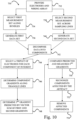
- a flow chart 730 exemplifies another (second) method for recognizing and suppressing an artifact (e.g. motion artifact and/or gradient artifact) generated in an EEG measurement in the presence of a magnetic field.
- Method 730 is based on the fact that a source of the electric field inside a patient's head produces electric potentials (neural signals) that are predictably distributed between EEG electrodes according to the electrodes' positions on the scalp.
- the method 730 of the invention will be hereafter referred to as an estimated-versus-measured (EVM) technique, and is capable of detecting and suppressing both BCG and NBCG interference related to any motion.
- EVM estimated-versus-measured
- an electrode array and a wiring array are provided, such that at least some measurements can be performed between electrodes not connected to the same sampling lines.
- the electrode array also includes one or more bundles (as described, for example, in Fig. 2 ) to enable measurements between electrodes connected to the same bundle.
- measurements across sampling lines are selected, and at 740, a data set indicative of such measurements across sampling lines is generated (in a manner similar to steps 708 and 710 of Fig. 9 ).
- a data set indicative of such measurements along bundles is generated (in a manner similar to steps 704 and 706 of Fig. 9 ).
- the full data set (whether it comprises only data indicative of measurements across bundles, along bundle, or both) is decomposed into components, similarly to the step 712 of Fig. 9 .
- a triplet of electrodes (named, for example A, B, and C) is selected for one or more component of the measured signals at 744.
- each triplet at least one of the electrodes is connected to a sampling line to which the other two are not connected. For example, this may be achieved when all three electrodes are connected to three different sampling lines or when two of the electrodes are connected to wires of the same bundle while the third electrode is connected to a different sampling line.
- a triplet corresponding to a specific component is chosen by identifying the highest effect of the specific component on a bipolar measurement, and determining a first pair of electrodes (for example A and B) corresponding to such bipolar measurement. After the first pair has been found, two more adjacent electrode pairs are selected (pair BC and pair AC), such that a bipolar measurement has been performed in steps 734 and/or 738 between the electrodes corresponding to both pairs.
- a triangle ABC is formed between the electrode triplet.
- the selection of the pair corresponding to the component's maximal effect is especially advantageous in ICA or PCA, where components typically approximate the signals generated by physical independent sources, when such component values are at or near their maximal values. Conversely, at or near their minimal values, the ICA or PCA components may not correspond to any physical source at a given location, and are rather spurious signals artificially created by the mathematical operations of ICA or PCA.
- the maximal effect of a specific component corresponds to the element w ij (weight) having the maximal absolute value on the column of matrix W which corresponds to a specific component.
- the row to which the element w ij belongs is used in order to determine the first pair of electrodes.
- the component gradients along the lines of the triangle defined by the triple of electrodes or values indicative of (e.g. proportional to) such component gradients are identified. If the components were determined by ICA or PCA, the values indicative of such component gradients are the weights corresponding to the three electrode pairs.
- a vector sum of two gradients of the component along two of the triangle's sides is performed, in order to predicted the component's gradient along the triangle's third side.
- the vector sum of two values indicative of such two gradients is performed, in order to predict the third value indicative of the component's gradient along the triangle's third side.
- the predicted component (or value indicative thereof) is compared to the component's gradient along the triangle's third side determined during the decomposition step 742 (or to the value indicative of the third component, as determined during the decomposition step 742).
- the vector sum of the component's gradients along the lines AB and BC is a vector along the line AC; conversely, if the component is an artifact (induced by movement of EEG electrode cables and/or of an EEG amplifier inside magnetic field and/or by a changing magnetic field), the component's gradient along the line AC does not correspond to vector sum of the component's gradients along the lines AB and BC.
- the comparison between the third gradient predicted at 748 and calculated at 742 enables the identification of components affected or generated by an artifact, at 752.
- a relation such as a ratio or a difference, for example
- the component is therefore deemed to correspond to a physical source within the brain or to an artifact according to the result of the comparison to the threshold value.
- the components affected or generated by an artifact are removed, while the components deemed to be generated by the brain are retained.
- a corrected signal can be recomposed using only the retained components.
- the corrected signal is a signal which is significantly unaffected by the artifact.
- steps 744 to 754 relate to using measurements between a triplet of electrodes for identifying artifacts
- the present invention is not limited to such feature. Rather, any number N of electrodes may be used for each component, as long as N>2 and as long as at least two of the electrodes are connected to the same bundle while at least one of the electrodes is connected to a different sampling line.
- the estimated component (or value indicative thereof) is found by a sum of N-1 vectors extending along the sides of the N-sided polygon formed by the N electrodes. The estimated component (or value indicative thereof) and is then compared to the component (or value indicative thereof) determined during the decomposition step 742 in order to establish whether the component is of neural origin or an artifact.
- the EVM technique described in method 730 may be applied to identify and suppress artifacts by itself, the EVM technique may be performed in conjunction with another artifact identification technique, in order to increase the discriminative power of such a technique.
- steps 744 to 752 of method 730 may be added between steps 718 and 720 of the VSM method 700 of Fig. 9 .
- steps 744 to 752 of method 730 may be added between steps 718 and 720 of the VSM method 700 of Fig. 9 .
- steps 744 to 752 of method 730 may be added between steps 718 and 720 of the VSM method 700 of Fig. 9 .
- steps 744 to 752 of method 730 may be added between steps 718 and 720 of the VSM method 700 of Fig. 9 .
- at least some of the components that are deemed to be affected or generated by an artifact in the method 700 can be further analyzed in order to avoid mistakenly classifying components generated by physical portion of the brain as artifact-affected or artifact-
- the method of flowchart 730 is preferably used in a system that includes a wiring array having at least one bundle to which a series of electrodes are connected and at least one sampling line which is connected to an electrode which is not connected to the bundle.
- a wiring array having at least one bundle to which a series of electrodes are connected and at least one sampling line which is connected to an electrode which is not connected to the bundle.
- the artifacts are generated by all parts of the electric loop: namely, (i) the section of head between electrodes, (ii) the wires, and (iii) an amplifier (if present).
- the portion of artifact generated by the section of the head between electrodes is larger than the portions of artifact generated by the wires. Therefore, the artifact generated within the section of the head may be distributed between EEG electrodes according to the electrodes' positions on the scalp.
- a further advantage may be attained by performing the method of flowchart 730 in a system which includes a wiring array having a net-like structure formed by two intersecting groups of spaced-apart sampling lines (which may be all or include some wire bundles, as described above in Figs 1-2 , and Figs 4 to 7 ), as such a wiring array assists to optimal ICA or PCA components discrimination. This is because if the bundles extended parallel to a single axis, then a neural activity producing a neural signal having a gradient that is mostly in the direction of across bundles may be sampled with poor signal to noise ratio. This may lead to wrong decomposition into components, which can result in an erroneous identification of such neural signal as noise.
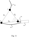
- FIG. 11 an example is provided, explaining one way to apply some steps of the method 730 in Fig. 10 in order to recognize an artifact.
- Three electrodes A, B, and C constitute or are part of an electrode array used for measure a plurality of signals.
- the electrode A and B are respectively connected to the wires 780 and 782, both wires, which may, for example, belong to a single bundle 784.
- the loop created by the wires 780 and 782 is therefore relatively small.
- the electrodes A and B are adjacent electrodes and are connected to adjacent wires, such that the electrical loop created by the wires is even smaller.
- the electrode C is connected to a wire 786, which belongs to a sampling line forming a relatively large loop with the bundle 784. It should be noted that for the purposes of the EVM technique, the electrodes A and B need not be connected to the same bundle.
- At least one of the electrode pairs (A-B, B-C , and C-A) be constituted by electrodes connected to different sampling lines.
- a certain component s i is analyzed by using the electrodes A, B, and C.
- the component s i is calculated by using measured EEG data obtained while the EEG electrodes were within a magnetic field (e.g. generated by an MRI or MRS scanner, or a TMS device) (see, for example, steps 704, 706, 708, and 710 in Fig. 9 ).
- a component s i has a gradient s i AB in the direction from the electrode A to the electrode B, a gradient s i BC in the direction from the electrode B to the electrode C, and a gradient s i CA in the direction from the electrode C to the electrode A.
- AB, BC, and AC are the distances between the electrodes A and B, B and C, and A and C respectively.
- the angle ⁇ is the angle between AB and BC.
- s i CA EST s i AB 2 + s i BC 2 ⁇ 2 s i AB . s i BC . cos ⁇ 1 / 2
- s i AB and s i BC are the magnitudes of the gradients of the component s i between the electrodes A and B, and B and C, respectively.
- the component s i can be classified as a neural signal originating within the head of the patient or test subject. If T is far from 1, the component is classified as a motion or interference artifact originating from cables or amplifier.
- T is compared to a predetermined threshold in order to classify the component s.
- the choice of such predetermined threshold defined whether the EVM technique is strict or permissive.
- a strict EVM technique can efficiently recognize and suppress most artifacts, but may also mistakenly suppress neural signals.
- a permissive EVM retains more of the neural signals, but may also retain more of the artifacts, compared to strict EVM.
- a possible permissive EVM technique may be achieved by recognizing as neural signals those components that satisfy the condition 0.5 ⁇ T ⁇ 2.
- a possible strict EVM technique may be achieved by recognizing as neural signals those components that satisfy the condition 0.75 ⁇ T ⁇ 1.5.
- the above geometrical analysis of the component s i can be performed only if the distances AB, BC, and CA along the head's surface and the angle ⁇ can be measured or calculated to a sufficient degree of accuracy. It should be noted that the head is not an ideal sphere. Therefore, if the distances between electrodes are comparable with the head's circumference, an accurate measurement/calculation of the distances AB, BC, and CA and of the angle ⁇ should take into account both the changes in the head's curvature and the electrode distances along the head's surface. It is therefore preferable to keep the distances AB, BC, and CA substantially smaller than the head's circumference, in order to easily measure or calculate such distances.
- the distances AB, BC, and CA and the angle ⁇ may be, for example, because at least one of the electrodes is within the patient's or test subject's head, as is the case in intracranial EEG.
- geometrical information about the electrodes configuration used in the system e.g. on the scalp and/or in the head
- neural signals outside a magnetic field - can be obtained via measurement of neural signals outside a magnetic field - provided that the same electrode array is used (or virtually recalculated via a different EEG array), and that effect of interference outside the magnetic field is substantially lower than the neural signal.
- a neural signal x is measured outside the magnetic field.
- x AB , x BC and x CA are gradients of the signal x along AB, BC and CA, respectively, measured outside the scanner.
- the electrode array can be used for EEG measurements in the presence of a magnetic field.
- signals are measured and decomposed into components.
- the component s i has gradients s i AB , s i BC , and s i CA .
- the magnitude Si CA EST of the diagonal gradient s i CA estimated by the vector sum between the gradients s i AB and s i BC is estimated. In this manner a ratio between s i CA EST and s i CA in the presence of magnetic field can be found, according to equation 16, in order to determine whether the signal s is a neural signal or an artifact.
- FIG. 12 there is schematically shown a system 800 of the present invention, for optimizing EEG measurements by recognizing and suppressing an artifact generated in the EEG measurement in the presence of a magnetic field.
- the system 800 includes an electrode arrangement 802, a wiring array 804, and an EEG monitor 504. The latter is associated with a control unit 808.
- the control unit 808 is either a utility integral with the EEG monitor 504, or a separate unit connected to the EEG monitor 504 via wires or wireless signal transmission.
- the control unit includes inter alia a processing utility configured and operable for receiving and processing the EEG data from the EEG monitor 504.
- Electrodes 810, 811, 812, 813, and 814 are shown in the present example, are disposed along the scalp of patient 306 according to a certain configuration, for example according to the International 10-20 system.
- the wiring array 804 includes different bundles (816, 817, and 818, for example) of wires tightly held together, for example as shown in Fig. 2 .
- the bundles may be arranged along substantially parallel axes or intersecting axes, and can thus be parallel, non-parallel, or crossing.
- the wiring array may or may not be formed of two groups of bundles extending along substantially perpendicular axes (as in the embodiment of Fig. 1 ), but may include substantially parallel bundles.
- crossing bundles arrangement e.g. a two-group net structure similar to that of Fig. 1 , would even more improve the motion artifact reduction. This is because the presence of crossing bundles enables a comparison of EEG measurements performed along and across bundles between the crossing (non-parallel) bundle groups.
- crossing bundles for example, perpendicular bundle groups
- a net structure of crossing bundles enables measurements across and along bundles to be performed in two directions (across and along the first bundle group, and across and along the second bundle group).
- Components substantially unaffected by an artifact would greatly affect both the measurements across bundles in the group perpendicular to the neural signal and the measurements along bundles in the group not perpendicular (for example parallel) to the neural signal in about the same manner, because of the direction of the neural signal.
- components affected by an artifact would greatly affect measurements across bundles in the group perpendicular to the neural signal, but would have a lesser effect on measurements along bundles in the group not perpendicular (for example parallel) to the neural signal. Therefore, the comparison of the maximal effects of components on data generated by measurements along and across bundles in two directions is used for recognizing the artifact-affected components.
- the electrodes are connected to the EEG monitor 504 via the wiring array 804.
- the EEG monitor 504 is designed for receiving the neural signals measured between electrode pairs and generating EEG measured data indicative thereof.
- the EEG monitor is capable of simultaneous reading of the measured data from multiple electrodes (electrode pairs).
- the EEG monitor may include a plurality of signal receiving channels, each for receiving a signal measured between a different pair of electrodes.
- the output of the EEG monitor 504 is thus indicative of a plurality of signals each corresponding to the measurement between a respective pair of electrodes.
- the control unit 808 receives the measured data and selects appropriate data pieces for processing.
- the selected data pieces correspond to the first and second sets of bipolar EEG measurements.
- the first set of bipolar EEG measurements includes measurements between at least one pair of electrodes connected to the same bundle. These may be for example the electrodes 810 and 812 connected to wires belonging to the same bundle 816, and/or the electrodes 811 and 813 connected to wires belonging to the same bundle 817.
- the second set of bipolar EEG measurements includes measurements performed only between electrodes of at least one pair connected to different bundles. For example, these may be the electrodes 810 and 814, and/or 812 and 813.
- the control unit 808 is designed and operable for the above described selection of the measured data pieces and for processing the selected data.
- the processing includes decomposing each data piece (presenting differential measurements, i.e. by at least one pair of electrodes) into a plurality of components as shown in step 712 of Fig. 8 .
- the processing may further include comparing the effect of the components on the first data set and on the second data set, and recognizing the artifact-affected signal components, satisfying a predetermined condition as described above with reference to steps 716 and 718 of Fig. 8 .
- the processing utility of the control unit 808 may include software modules configured for comparing gradients of components of measured signals to the estimates of said gradients obtained using geometrical information regarding the geometrical distribution of electrodes on and/or in the head of a patient or test subject, and recognizing the artifact-affected signal components, satisfying a predetermined condition as explained with reference to steps 744 to 752 of Fig. 10 . Then the processor utility of the control unit operates for subtracting each artifact-affected component from the corresponding piece of data and generating corrected EEG data (unaffected by the artifact or having significantly reduced artifact component), as described above, with reference to step 720 of Fig. 9 and/or step 754 of Fig. 10 .
- the control unit 808 may be preprogrammed with a certain separation algorithm, or is preferably preprogrammed with multiple algorithms of the kind specified and enables selection (by user or automatically) of a desired (optimal) separation algorithm.
- the control unit 808 may be programmable by a user, enabling the user to create the user's custom separation algorithm.
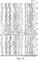
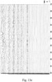
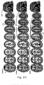
- Figs 13a-13f illustrating graphical representations of simultaneous EEG and fMRI measurements performed on a test subject, as well as graphical representations illustrating results yielded by the application of the VMS technique of Fig. 9 on the EEG measured data.
- a basic prototype of the electrode and wiring array was built.
- the first group of electrodes consisted of thirty electrodes connected to nine wire bundles extending parallel to a longitudinal axis, a reference electrode, and a ground electrode connected to one amplifier.
- a second group of electrodes consisted of thirty electrodes connected to nine wire bundles extending parallel to a transverse axis, a reference electrode, and a ground electrode connected to one amplifier connected to a second amplifier.
- Labels of electrodes correspond to labels of standard 10-20 montage except for electrodes Tp9 and Tp10 of transverse bundle, which were located on the forehead, above the eyebrows.
- Reference and ground electrodes were located at FCz and AFz respectively. All wires were made of nonmagnetic metal.
- the noise reduction method of Fig. 9 was implemented in MATLAB. EEG and FMRI data were analyzed in MATLAB.
- a subject with epilepsy was scanned in simultaneous EEG-fMRI using the prototype electrode array.
- the subjects had epileptic activity during the scan.
- Results show that the use of the electrode array and the VMS noise suppression method 700 of Fig. 9 significantly reduces artifacts induced by movement inside magnetic field, and allows detecting epileptic activity occurring in a deep source (e.g., located deep inside fissure, sulcus, insula or basal brain areas) (as demonstrated by corresponding fMRI activity) and characterized by low amplitude (i.e. low magnitude of EEG signal), that cannot be seen with state of the art technology (see Fig. 13a , for EEG with state of the art cleaning approach, and Fig. 13b for EEG with the developed noise suppression method).
- a deep source e.g., located deep inside fissure, sulcus, insula or basal brain areas
- low amplitude i.e. low magnitude of EEG signal
- EEG activity detection also enabled the identification of the focus of activity using the fMRI ( Fig. 13f ).
- the results obtained for the patient were in most cases correlated with epileptogenic zone location hypothesis.
- the below results suggest that the developed technology can be used effectively and reliably to identify focal epileptic activity and location of its origin in the brain.
- the type C spike is correlated with blood-oxygen-level dependent (BOLD) deactivation in bilateral, frontal, more right than left regions of the brain (the BOLD deactivation being identified by fMRI scans). Deactivation also appeared in parieto-occipital midline region.
- BOLD blood-oxygen-level dependent
- Type A spike was according to EEG a focal, right frontal spike, mainly with transverse EEG gradient. This spike appeared mostly after type C bursts.
- the BOLD correlates of type A spikes include deactivation in right and left dorsolateral frontal regions 900, bilateral parietal and mesial occipito-parietal regions 901, as can be seen in Fig. 13f . These patterns correspond to default mode network activity, therefore they are not specific.
- Spike C correlates of BOLD activity include activation patterns in the right frontal dorsolateral and mesial 902 regions as well as occipital regions 903.
- Type B spike was often independent, or appeared before type C bursts. Its transverse EEG gradient was mainly central. Its longitudinal gradient was mainly fronto-central. As can be seen in Fig. 13f , the type B spike correlated with BOLD activation in right superior frontal and dorso-lateral regions 904 with extension to the mesial surface 905. Resulting fMRI activation pattern corresponded well to the semiology of patient's seizures which were short and started with unclear head sensation, progressed to left hand clonic movements with some disorientation.
- activation in right frontal mesial regions (905 and 902) close to cingulate gyrus corresponds to vague head feeling while right dorso-lateal activation (904) and right frontal mesial region activation close to SMA corresponds to clonic left-hand movements.
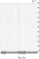
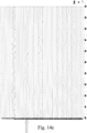
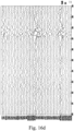
- Fig. 14a shows a representation of an EEG signal of a test subject over time as detected by a plurality of electrode pairs.
- the EEG signal shown in Fig. 14a has been decomposed into components via ICA, and recomposed after identification and removal of components that were deemed to be artifacts according to the VMS technique described in Fig. 9 .
- the removed components were deemed to be artifacts, since their effect was significantly higher measurement across bundles than they were on measurements along bundles.
- a small epileptic spike is observable just before 496 seconds of recording.
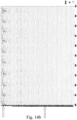
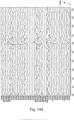
- Fig. 14b illustrates the ICA components of the EEG measured data before artifact removal.
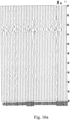
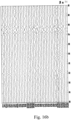
- Fig. 14c shows the ICA components of the EEG measured data after artifact suppression, i.e. after zeroing the noise components that have highest weights on measurements across bundles and retaining the components related to brain signal.
- component No. 2 (marked with an arrow) is a cardiobalistic noise component that was removed accordingly by artifact suppression.
- the following geometrical considerations were then used according to the EVM technique of Fig. 10 , in order to determine whether the removal of component No. 2 was justified.
- a suitable electrode triplet was selected (step 744 of Fig. 10 ).
- the electrode pair in which the measurement was most strongly affected by component No. 2 was identified as the pair including the electrodes C3 and P3 (bipolar channel C3-P3).
- Adjacent bipolar channels forming a triangle were identified as the P3-Cp1 and Cp1-C3 channels.
- Weights associated with component No. 2, termed, were identified along the three electrode pairs (step 746 of Fig. 10 ), where w 1 was the weight corresponding to the C3-P3 channel, w 2 was the weight corresponding to the P3-Cp1 channel, and w 3 was the weight corresponding to the Cp1-C3 channel.
- D 1 was the distance between the electrodes C3 and P3.
- D 2 was the distance between the electrodes P3 and Cp1.
- D 3 was the distance between the electrodes C3 and Cp1. The sign of the weights depended on the direction of measurement.
- the gradient along the Cp1-C3 line predicted by a vector sum of the gradient along the C3-P3 line and the gradient along the P3-Cp1 line was calculated (step 748 of Fig. 10 )
- s i 3 EST s i 1 2 + s i 2 2 ⁇ 2 s i 1 . s i 2 . cos ⁇ 1 / 2
- s i 3 EST is the estimated gradient of the component No 2 along the line connecting the electrodes C3 and Cp1
- s i 1 is the gradient of the component No 2 along the line connecting the electrodes C3 and P3
- s i 2 is the gradient of the component No 2 along the line connecting the electrodes P3 and Cp1.
- component No. 2 was much larger than the weight calculated from the measured EEG data. Hence it was concluded that component No. 2 did not obey geometrical considerations and had been justifiably identified as an artifact (step 752 of Fig. 10 ) and rejected (step 754 of Fig. 10 ).
- Component No. 18 (marked with an arrow in Fig. 14c ) was preserved by the VMS technique of Fig. 9 . Hence it is probably a brain signal component. A geometrical analysis analogous to that performed above, with reference to component No. 2, was also performed for component No. 18.
- Component No. 35 (marked with an arrow in Fig. 14b ) was removed by the VMS technique of Fig. 9 . However, the behavior in time of component No. 35 reveals that component No. 35 may have contained some of the spike signal seen in 496 sec. It was therefore postulated that component No. 35 was mistakenly removed.
- component No. 35 was therefore performed according to the EVM technique of Fig. 10 .
- the highest weight of component No. 35 belonged to the bipolar channel Fp1-C3.
- Adjacent channels forming a triangle are F3-Fz and Fz-Fp1.
- Fig. 16a illustrates a corrected EEG signal reconstructed after the application of a strict EVM technique on measured EEG data (components in which 0.75 ⁇ T ⁇ 1.5 are recognized as artifacts, as explained above, with reference to Fig. 10 );
- Fig. 16b illustrates a corrected EEG signal reconstructed after the application of a strict VMS technique on measured EEG data (components in which w MAX1 and w MAX2 correspond to pieces of data generated by measurements across bundles are recognized as artifacts, as explained above, with reference to Fig. 9 );
- Fig. 16a illustrates a corrected EEG signal reconstructed after the application of a strict EVM technique on measured EEG data (components in which 0.75 ⁇ T ⁇ 1.5 are recognized as artifacts, as explained above, with reference to Fig. 10 );
- Fig. 16b illustrates a corrected EEG signal reconstructed after the application of a strict VMS technique on measured EEG data (components in which w MA
- FIG. 16c illustrates a corrected EEG signal reconstructed after the application of a permissive EVM technique on measured EEG data (components in which 0. 5 ⁇ T ⁇ 2 are recognized as artifacts, as explained above, with reference to Fig. 10 ); and Fig. 16d illustrates a corrected EEG signal reconstructed after the application of a permissive VMS (components in which R ⁇ 0.5 are recognized as artifacts, as explained above, with reference to Fig. 9 ) technique on measured EEG data.
- Fig. 17a illustrates a corrected EEG signal reconstructed after the application on EEG measured data of an artifact suppression technique constituted by a strict VMS technique and a strict EVM technique.
- Fig. 17b illustrates a corrected EEG signal reconstructed, after the application on EEG measured data of an artifact suppression technique constituted by a strict VMS technique and a permissive EVM technique.
- epileptic spike activity is seen near 387 seconds. It can be seen that the application of strict EVM ( Fig. 16a ) and strict VMS ( Fig. 16b ) led to good noise suppression, but also some epileptic signal was lost. Permissive EVM ( Fig. 16c ) and permissive VMS ( Fig. 16d ) led to more complete epileptic signal reconstruction, but also some nose was retained in the data. The combination of VMS and EVM ( Figs 17a-17b ) led to compromised results with satisfactory noise suppression and satisfactory epileptic signal reconstruction. More specifically, Fig. 17b demonstrates more details of epileptic signal than Fig. 17a . For example, in Fig.
Landscapes
- Health & Medical Sciences (AREA)
- Life Sciences & Earth Sciences (AREA)
- Medical Informatics (AREA)
- Biophysics (AREA)
- Pathology (AREA)
- Engineering & Computer Science (AREA)
- Biomedical Technology (AREA)
- Heart & Thoracic Surgery (AREA)
- Physics & Mathematics (AREA)
- Molecular Biology (AREA)
- Surgery (AREA)
- Animal Behavior & Ethology (AREA)
- General Health & Medical Sciences (AREA)
- Public Health (AREA)
- Veterinary Medicine (AREA)
- Psychiatry (AREA)
- Psychology (AREA)
- Magnetic Resonance Imaging Apparatus (AREA)
- Measurement And Recording Of Electrical Phenomena And Electrical Characteristics Of The Living Body (AREA)
Claims (16)
- Eine Messvorrichtung zur Verwendung bei Elektroenzephalogramm (EEG)-Messungen, die in Gegenwart eines Magnetfeldes durchgeführt werden, wobei die Messvorrichtung eine Verdrahtungsanordnung (100) zum Verbinden einer Elektrodenanordnung mit einer (EEG)-Überwachungsvorrichtung umfasst, wobei die Verdrahtungsanordnung (100) eine Mehrzahl von Probenahmeleitungen umfasst (102, 104, 106, 108), die so angeordnet sind, dass sie eine erste Gruppe G1 von Probenahmeleitungen und eine zweite Gruppe G2 von Probenahmeleitungen bilden (110, 112, 114); die erste Gruppe G1 von Probenahmeleitungen in einer beabstandeten, im Wesentlichen parallelen Beziehung angeordnet ist, die sich entlang einer ersten Achse erstreckt, wobei die genannte erste Gruppe G1 von Probenahmeleitungen Drahtbündel umfasst, die jeweils eine Mehrzahl von ersten Drähten zum Verbinden mit einer entsprechenden ersten Mehrzahl von Elektroden der genannten Elektrodenanordnung umfassen; die zweite Gruppe G2 von Probenahmeleitungen in einer beabstandeten, im Wesentlichen parallelen Beziehung angeordnet ist, die sich entlang einer zweiten Achse erstreckt, die sich mit der genannten ersten Achse kreuzt, so dass die erste Gruppe G1 von Probenahmeleitungen die zweite Gruppe von Probenahmeleitungen kreuzt (15), um eine Netzstruktur zu bilden, wobei die zweite Gruppe G2 von Probenahmeleitungen Drahtbündel umfasst, die jeweils eine Mehrzahl von zweiten Drähten zum Verbinden mit einer entsprechenden zweiten Mehrzahl von Elektroden der genannten Elektrodenanordnung umfassen;
Die Verdrahtungsanordnung ist so konfiguriert und verwendbar, dass sie die von der ersten und zweiten Mehrzahl von Elektroden gemessenen Signale in zwei Richtungen, quer und entlang der ersten Gruppe G1 der Probenahmeleitungen und quer und entlang der zweiten Gruppe G2 der Probenahmeleitungen, an die EEG-Überwachungsvorrichtung übertragt, wobei die Verdrahtungsanordnung so konfiguriert ist, dass sie EEG-Daten erzeugt, die kennzeichnend sind für ein neurales Signalprofil von EEG-Messungen mit einer verringerten Wirkung von der durch das Magnetfeld verursachten Bewegungs- und/oder Gradientenartefakten, indem die erste und die zweite Mehrzahl von Elektroden, die durch die entsprechende Mehrzahl von ersten und zweiten Drähten verbunden sind, die fest zusammengehalten oder miteinander verdrillt sind, entlang zweier Richtungen Probenahmen durchführen. - Eine Messvorrichtung nach Anspruch 1, wobei die zweite Achse im Wesentlichen senkrecht zur ersten Achse steht.
- Eine Messvorrichtung nach Anspruch 1 oder 2, wobei die durch die erste Gruppe G1 von Probenahmeleitungen und die zweite Gruppe G2 von Probenahmeleitungen gebildete Netzstruktur (300) für die Verbindung der EEG-Überwachungsvorrichtung mit der Elektrodenanordnung konfiguriert ist, wobei die Elektroden der Elektrodenanordnung eine der folgenden Konfigurationen aufweisen:(i) für die Positionierung entsprechend dem internationalen System 10-20 entlang der Kopfhaut des Patienten konfiguriert sind;(ii) mindestens einige der Elektroden sind so konfiguriert, dass sie auf eine der folgenden Arten am Patientenkopf angebracht werden können: nicht-invasiv an der Kopfhaut, semi-invasiv im epiduralen Kopfbereich und invasiv im subduralen Kopfbereich des Patienten angebracht.
- Eine Messvorrichtung nach einem der Ansprüche 1 bis 3, wobei mindestens einige der Probenahmeleitungen so konfiguriert sind, dass sie lösbar mit der ersten und zweiten Mehrzahl von Elektroden verbunden werden können, so dass zumindest einige der EEG-Elektroden zwischen den Scans ausgetauscht werden können.
- Eine Messvorrichtung nach einem der Ansprüche 1 bis 4, wobei mindestens eine der ersten und zweiten Gruppen von Probenahmeleitungen in mindestens zwei Untergruppen unterteilt ist, wobei mindestens eine der genannten ersten und zweiten Gruppen von Probenahmeleitungen der Untergruppen, die zu derselben Gruppe gehören, abwechselnd so angeordnet ist, dass zwei benachbarte Probenahmeleitungen, die zu einer bestimmten Gruppe gehören, zu verschiedenen Untergruppen dieser bestimmten Gruppe gehören.
- Eine Netzstruktur (300), die so konfiguriert ist, dass sie auf der Kopfhaut eines Patienten platziert und bei Elektroenzephalogramm-(EEG)-Messungen verwendet werden kann, die in Gegenwart eines Magnetfeldes durchgeführt werden, wobei die Netzstruktur (300) eine Verdrahtungsanordnung umfasst, die eine erste und eine zweite Gruppe von Probenahmeleitungen umfasst, die jeweils Drahtbündel umfassen, die jeweils eine Mehrzahl von entsprechenden ersten und zweiten Drähten umfassen, die sich entlang einer ersten und einer zweiten sich kreuzenden Achse erstrecken, wobei jede Gruppe der Probenahmeleitungen durch eine Mehrzahl von voneinander beabstandeten und im Wesentlichen parallelen Probenahmeleitungen gebildet wird, die so konfiguriert sind, dass sie EEG-Signale von einer entsprechenden Mehrzahl von voneinander beabstandeten EEG-Messstellen übertragen, wobei die Verdrahtungsanordnung so konfiguriert ist, dass sie EEG-Daten der EEG-Messungen mit einer verringerten Wirkung von Bewegungs- und/oder Gradientenartefakten liest, die durch das Magnetfeld von den Messstellen durch die erste und zweite Gruppe von Probenahmeleitungen in zwei Richtungen, quer und entlang der ersten Gruppe der Probenahmeleitungen und quer und entlang der zweiten Gruppe der Probenahmeleitungen verursacht werden, wobei die entsprechende Mehrzahl von ersten und zweiten Drähten fest zusammengehalten oder miteinander verdrillt ist.
- Eine Messvorrichtung zur Verwendung bei Elektroenzephalogramm (EEG)-Messungen, die in Gegenwart eines Magnetfeldes durchgeführt werden, wobei die Vorrichtung die Netzstruktur (300) nach Anspruch 6 und eine Mehrzahl von EEG-Elektroden und eine Verdrahtungsanordnung nach Anspruch 1 zum Verbinden der genannten Elektrodenanordnung mit einer EEG-Überwachungsvorrichtung umfasst.
- Ein Helm (400), der so konfiguriert ist, dass er von einem Patienten bei einer in Gegenwart eines Magnetfeldes Elektroenzephalogramm (EEG)-Messung getragen werden kann, wobei der Helm die Netzstruktur (300) nach Anspruch 6 trägt.
- Der Helm (400) nach Anspruch 8, weiterhin umfassend:eine Mehrzahl der EEG-Elektroden, die durch die Verdrahtungsanordnung an die EEG-Überwachungsvorrichtung anschließbar sind; undein elektrisch nichtleitendes Kopfstück (406), umfassend:eine innere Oberfläche, die so konfiguriert ist, dass sie auf dem Patientenkopf angebracht werden kann;eine äußere Oberfläche, die die Verdrahtungsanordnung trägt; undeine Mehrzahl der Öffnungen (408), wobei jede Öffnung so konfiguriert ist, dass sie von einem Teil einer der genannten EEG-Elektroden zum Anschluss an einen der Drähte durchquert wird.
- Ein System (800) für gleichzeitigen EEG- und MRT-Scan bestehend aus:einer magnetfeldbasierten Vorrichtung mit mindestens einem MRT-Scanner (502) zur bildgebenden Untersuchung des Gehirns des Patienten, und einer Spulenvorrichtung zur transkraniellen Magnetstimulation (TMS) zur Erzeugung eines wechselnden Magnetfeldes, um Aktivität im Gehirn des Patienten zu erzeugen;einer Verdrahtungsanordnung (804), die eine EEG-Überwachungsvorrichtung (504) und eine Mehrzahl von EEG-Elektroden (802) verbindet, die so konfiguriert sind, dass sie an vorbestimmten Stellen auf der Kopfhaut des Patienten platziert werden und ein neurales Signal erfassen können;eine Messvorrichtung nach einem der Ansprüche 1 bis 5 zur Weiterleitung der neuralen Signale an die EEG-Überwachungsvorrichtung zur Analyse der genannten Signale und Erzeugung von EEG-Daten, wobei die EEG-Daten aufgrund der Netzstruktur (300) der Verdrahtungsanordnung (804) ein verringertes Bewegungsartefakt aufweisen.
- Das System nach Anspruch 10, gekennzeichnet durch mindestens eines der folgenden:(i) das Magnetfeld ist ein vom MRT-Scanner erzeugtes Magnetfeld, wobei die EEG-Daten vom verringerten Bewegungsartefakt betroffen sind;(ii) das Magnetfeld ist ein wechselndes, vom TMS-Spulenvorrichtung erzeugtes Magnetfeld, wobei die EEG-Daten mindestens vom verringerten Magnetpuls-Artefakt betroffen sind;(iii) dieselbe Probenahmeleitung mit einem Elektrodenpaar verbunden werden kann, das für die bipolaren Messungen konfiguriert ist.
- Das System nach Anspruch 10 oder 11, wobeidie Elektrodenanordnung eine Referenzelektrode, jeweils ein erstes und ein zweites Signal umfasst, wobei die erste und die zweite Elektrode mit derselben Probenahmeleitung verbunden sind; unddie an der EEG-Überwachungsvorrichtung erzeugten EEG-Daten eine Kombination aus den genannten ersten und zweiten Signalen sind, und kennzeichnend sind für ein Signal zwischen der ersten und der zweiten Elektrode, wodurch die EEG-Daten mit mindestens einem von verringerter Bewegungs- und Gradientenartefakten bereitgestellt werden.
- das System nach einem der Ansprüche 10 bis 12, wobei die genannte EEG-Überwachungsvorrichtung (504) mit einer zentralen Steuervorrichtung (808) assoziiert ist, die so konfiguriert und betreibbar ist, dass sie EEG-Daten empfängt und daraus vorbestimmte Datenteile auswählt und die Datenteile analysiert, um ein bei der EEG-Messung erzeugtes Artefakt zu erkennen und zu unterdrücken.
- Verfahren zur Durchführung einer Elektroenzephalogramm (EEG)-Messung in Gegenwart eines Magnetfeldes, wobei das Verfahren umfasst:stellt ein Magnetfeld bereit, das entweder ein konstantes Magnetfeld oder ein wechselndes Magnetfeld ist;stellt eine Elektrodenanordnung bereit, die eine Mehrzahl von EEG-Elektroden umfasst, die auf dem Patientenkopf angebracht sind;Verbinden der Mehrzahl von EED-Elektroden mit einer EED-Überwachungsvorrichtung unter Verwendung einer Verdrahtungsanordnung, die eine erste Gruppe G1 von Probenahmeleitungen umfasst, die in einer beabstandeten, im Wesentlichen parallelen Beziehung angeordnet sind, und sich entlang einer ersten Achse erstrecken, wobei die erste Gruppe G1 von Probenahmeleitungen eine erste Gruppe von Drahtbündeln umfasst, wobei die erste Gruppe von Drahtbündeln eine Mehrzahl von ersten Drähten mit unterschiedlichen Längen zum Verbinden mit einer entsprechenden ersten Mehrzahl von Elektroden der Elektrodenanordnung umfasst; und eine zweite Gruppe G2 von Probenahmeleitungen, die in einer beabstandeten und im Wesentlichen parallelen Beziehung angeordnet sind, die sich entlang einer zweiten Achse erstreckt, und sich mit der ersten Achse kreuzt, so dass die zweite Gruppe G2 von Probenahmeleitungen die erste Gruppe G1 von Probenahmeleitungen kreuzt, um eine Netzstruktur zu bilden (300), wobei die zweite Gruppe G2 von Probenahmeleitungen eine zweite Gruppe von Drahtbündeln umfasst, wobei jedes der zweiten Drahtbündel eine Mehrzahl von zweiten Drähten mit unterschiedlichen Längen zur Verbindung mit einer entsprechenden zweiten Mehrzahl von Elektroden der Elektrodenanordnung umfasst;Messen von neuralen Signalen über die erste und zweite Mehrzahl von Elektroden in zwei Richtungen, quer und entlang der ersten Gruppe der Probenahmeleitungen und quer und entlang der zweiten Gruppe der Probenahmeleitungen;Übertragen der gemessenen neuralen Signale an die Überwachungsvorrichtung über die Verdrahtungsanordnung; undIn dem Überwachungsfahrzeug, das die gemessenen neuralen Signale empfängt und EEG-Daten von EEG-Messungen mit einer verringerten Wirkung von Bewegungs- und/oder Gradientenartefakten liefert, die durch das Magnetfeld verursacht werden, das kennzeichnend ist für die gemessenen neuralen Signale zwischen mindestens einem Paar von Elektroden, die mit demselben Bündel der Verdrahtungsanordnung verbunden sind, und mindestens einem Paar von Elektroden, die mit den sich kreuzenden Probenahmeleitungen verbunden sind, wobei die Elektroden durch die entsprechende Mehrzahl von ersten und zweiten Drähten verbunden sind, die fest zusammengehalten oder miteinander verdrillt sind.
- Das Verfahren nach Anspruch 14, das mindestens eines der folgenden umfasst:Messen des neuralen Signals zwischen zwei beliebigen der Elektroden, die mit Drähten verbunden sind, die zu einer der Probenahmeleitungen gehören;Messen des neuralen Signals zwischen einem Referenzelektroden der genannten Elektroden und mindestens einigen der genannten Elektroden; undVerarbeiten der EEG-Daten, wobei die Verarbeitung mindestens eines der folgenden umfasst: Berechnen einer Amplitude und einer Ausrichtung des genannten neuralen Signals; und Auswählen vorbestimmter Datenteile aus den EEG-Daten, Analysieren der genannten Datenteile, und Erkennen und Unterdrücken eines bei der EEG-Messung erzeugten Artefakts.
- Verfahren nach Anspruch 15, wobei das genannte Auswählen von vorbestimmten Datenteilen aus den EEG-Daten das Auswählen eines ersten Satzes von Signalmessungen der neuralen Signalmessung zwischen einer ersten Gruppe von Elektrodenpaaren umfasst, so dass jede Elektrode der ersten Gruppe von Elektrodenpaaren mit Drähten verbunden ist, die zu demselben Drahtbündel gehören, und das Auswählen eines zweiten Satzes von Signalmessungen zwischen einer zweiten Gruppe von Elektrodenpaaren, so dass jede Elektrode der zweiten Gruppe von Elektrodenpaaren mit einem Draht verbunden ist, der zu verschiedenen Probenahmeleitungen gehört; und
das Analysieren der ausgewählten Datenteile und das Erkennen und Unterdrücken eines bei der Messung erzeugten Artefakts umfasst:Anwenden eines Trennungsalgorithmus auf den ersten und zweiten Satz, um gemeinsam Datenteile des ersten und zweiten Satzes von Signalmessungen, die kennzeichnend für das Signal ist, in eine Mehrzahl von Komponenten zu zerlegen;Vergleichen einer Auswirkung von mindestens einigen der Mehrzahl von Komponenten auf jeden der ersten und zweiten Sätze von Signalmessungen; undErkennen von mindestens einer spezifischen Komponente aus der genannten Mehrzahl von Komponenten, die eine Auswirkung auf den zweiten Satz von Messungen hat, die höher ist als eine Auswirkung auf den ersten Satz von Messungen, und Kennzeichnen der spezifischen Komponente als eine durch ein Artefakt beeinflusste Komponente.
Applications Claiming Priority (3)
| Application Number | Priority Date | Filing Date | Title |
|---|---|---|---|
| US39072210P | 2010-10-07 | 2010-10-07 | |
| US201161445080P | 2011-02-22 | 2011-02-22 | |
| PCT/IL2011/000785 WO2012046237A2 (en) | 2010-10-07 | 2011-10-06 | Device for use in electro-biological signal measurement in the presence of a magnetic field |
Publications (2)
| Publication Number | Publication Date |
|---|---|
| EP2624748A2 EP2624748A2 (de) | 2013-08-14 |
| EP2624748B1 true EP2624748B1 (de) | 2024-05-01 |
Family
ID=44971067
Family Applications (1)
| Application Number | Title | Priority Date | Filing Date |
|---|---|---|---|
| EP11782479.7A Active EP2624748B1 (de) | 2010-10-07 | 2011-10-06 | Vorrichtung zur verwendung in der electrobiologischen signalmessung in gegenwart eines magnetfeldes |
Country Status (3)
| Country | Link |
|---|---|
| US (1) | US9636019B2 (de) |
| EP (1) | EP2624748B1 (de) |
| WO (1) | WO2012046237A2 (de) |
Families Citing this family (32)
| Publication number | Priority date | Publication date | Assignee | Title |
|---|---|---|---|---|
| CN102847231B (zh) * | 2012-04-20 | 2015-02-25 | 南京理工大学 | 一种动态可变多通道经颅磁刺激线圈阵列及其控制方法 |
| JP2016523125A (ja) | 2013-05-30 | 2016-08-08 | グラハム エイチ. クリーシー | 局所神経性刺激 |
| US11229789B2 (en) | 2013-05-30 | 2022-01-25 | Neurostim Oab, Inc. | Neuro activator with controller |
| WO2015009877A1 (en) * | 2013-07-17 | 2015-01-22 | The Regents Of The University Of California | Method for focused recording and stimulation electrode array |
| US9747421B2 (en) * | 2014-02-10 | 2017-08-29 | Picofemto LLC | Multi-factor brain analysis via medical imaging decision support systems and methods |
| US11077301B2 (en) | 2015-02-21 | 2021-08-03 | NeurostimOAB, Inc. | Topical nerve stimulator and sensor for bladder control |
| US10542961B2 (en) | 2015-06-15 | 2020-01-28 | The Research Foundation For The State University Of New York | System and method for infrasonic cardiac monitoring |
| KR20180039667A (ko) * | 2015-09-07 | 2018-04-18 | 더 리전트 오브 더 유니버시티 오브 캘리포니아 | 초고밀도 전극 기반 뇌 이미징 시스템 |
| US20170105645A1 (en) * | 2015-10-19 | 2017-04-20 | Yeda Research And Development Co. Ltd. | Electroencephalography with application of transcranial magnetic stimulation |
| WO2019060298A1 (en) | 2017-09-19 | 2019-03-28 | Neuroenhancement Lab, LLC | METHOD AND APPARATUS FOR NEURO-ACTIVATION |
| EP3477583A1 (de) * | 2017-10-31 | 2019-05-01 | Koninklijke Philips N.V. | Auf deep-learning basierte verarbeitung von bewegungsartefakten in magnetresonanz-bildgebungsdaten |
| US10953225B2 (en) | 2017-11-07 | 2021-03-23 | Neurostim Oab, Inc. | Non-invasive nerve activator with adaptive circuit |
| WO2019100102A1 (en) * | 2017-11-24 | 2019-05-31 | Seer Medical Pty Ltd | An eeg monitoring apparatus and method of its placement |
| US11717686B2 (en) | 2017-12-04 | 2023-08-08 | Neuroenhancement Lab, LLC | Method and apparatus for neuroenhancement to facilitate learning and performance |
| US11318277B2 (en) | 2017-12-31 | 2022-05-03 | Neuroenhancement Lab, LLC | Method and apparatus for neuroenhancement to enhance emotional response |
| US12280219B2 (en) | 2017-12-31 | 2025-04-22 | NeuroLight, Inc. | Method and apparatus for neuroenhancement to enhance emotional response |
| US11364361B2 (en) | 2018-04-20 | 2022-06-21 | Neuroenhancement Lab, LLC | System and method for inducing sleep by transplanting mental states |
| KR102124430B1 (ko) * | 2018-07-16 | 2020-06-18 | 고려대학교 산학협력단 | Bmi용 eeg 최소 전극 선택 방법 및 상기 방법을 수행하기 위한 저장 매체 |
| CN113382683A (zh) | 2018-09-14 | 2021-09-10 | 纽罗因恒思蒙特实验有限责任公司 | 改善睡眠的系统和方法 |
| CN113271856A (zh) * | 2018-10-22 | 2021-08-17 | 爱思神经系统公司 | 优化用于短期半球脑监测的帽状腱膜下电极阵列的床边插入和记录功能的系统和方法 |
| US11696713B2 (en) * | 2019-03-15 | 2023-07-11 | Arizona Board Of Regents On Behalf Of Arizona State University | Contour electrocorticography (ECoG) array |
| US11786694B2 (en) | 2019-05-24 | 2023-10-17 | NeuroLight, Inc. | Device, method, and app for facilitating sleep |
| WO2020264214A1 (en) | 2019-06-26 | 2020-12-30 | Neurostim Technologies Llc | Non-invasive nerve activator with adaptive circuit |
| US11881881B2 (en) * | 2019-11-28 | 2024-01-23 | Ricoh Company, Ltd. | Determination apparatus, biomagnetism measuring apparatus, and determination method |
| WO2021126921A1 (en) | 2019-12-16 | 2021-06-24 | Neurostim Solutions, Llc | Non-invasive nerve activator with boosted charge delivery |
| US20240108272A1 (en) * | 2020-03-13 | 2024-04-04 | Ichilov Tech Ltd. | Eeg electrode array and method of use |
| US12125593B2 (en) | 2020-10-05 | 2024-10-22 | The Trustees Of Columbia University In The City Of New York | Systems and methods for fusing EEG and fMRI through hierarchical deep transcoding |
| US20230355156A1 (en) * | 2020-12-09 | 2023-11-09 | The Regents Of The University Of California | High resolution electroencephalograph signal acquisition system |
| CN113100780B (zh) * | 2021-03-04 | 2022-07-26 | 北京大学 | 同步脑电-功能磁共振数据的自动化处理方法 |
| CN113040789B (zh) * | 2021-03-17 | 2022-09-09 | 华南理工大学 | 一种同步EEG-fMRI数据采集中核磁伪迹的在线去除方法 |
| WO2023215736A2 (en) * | 2022-05-02 | 2023-11-09 | The General Hospital Corporation | Systems and methods for electrophysiological signal recording and position or motion monitoring during magnetic resonance imaging |
| CN115153561B (zh) * | 2022-07-11 | 2024-12-31 | 西南大学 | 一种fMRI电磁兼容的柔性贴片电极 |
Family Cites Families (12)
| Publication number | Priority date | Publication date | Assignee | Title |
|---|---|---|---|---|
| US3998213A (en) * | 1975-04-08 | 1976-12-21 | Bio-Volt Corporation | Self-adjustable holder for automatically positioning electroencephalographic electrodes |
| AU667199B2 (en) * | 1991-11-08 | 1996-03-14 | Physiometrix, Inc. | EEG headpiece with disposable electrodes and apparatus and system and method for use therewith |
| US5687724A (en) * | 1993-10-26 | 1997-11-18 | Abratech Corporation | Apparatus and method for determining variations in measured physical parameters of signal-generators |
| HRP970562A2 (en) | 1997-11-04 | 2000-10-31 | Pavić Milica | Universal eeg cap |
| US6708051B1 (en) * | 1998-11-10 | 2004-03-16 | Compumedics Limited | FMRI compatible electrode and electrode placement techniques |
| US6510340B1 (en) * | 2000-01-10 | 2003-01-21 | Jordan Neuroscience, Inc. | Method and apparatus for electroencephalography |
| US10327701B2 (en) | 2005-05-06 | 2019-06-25 | The General Hospital Corporation | Apparatuses and methods for electrophysiological signal delivery and recording during MRI |
| US7715894B2 (en) * | 2005-11-10 | 2010-05-11 | Conopco, Inc. | Apparatus and method for acquiring a signal |
| DE602006006818D1 (de) * | 2006-06-30 | 2009-06-25 | Gen Electric | Verfahren und System für Mehrkanalbiosignal-Verarbeitung |
| US9345418B2 (en) * | 2007-03-27 | 2016-05-24 | Dignity Health | EEG net with transmission capabilities |
| US20100286549A1 (en) * | 2007-12-18 | 2010-11-11 | New York University | System and Method for Assessing Efficacy of Therapeutic Agents |
| US20100022907A1 (en) * | 2008-05-14 | 2010-01-28 | The Hospital For Sick Children | Methods based on fluctuations in cortical synchronization |
-
2011
- 2011-10-06 WO PCT/IL2011/000785 patent/WO2012046237A2/en not_active Ceased
- 2011-10-06 EP EP11782479.7A patent/EP2624748B1/de active Active
- 2011-10-06 US US13/878,297 patent/US9636019B2/en active Active
Also Published As
| Publication number | Publication date |
|---|---|
| WO2012046237A2 (en) | 2012-04-12 |
| US9636019B2 (en) | 2017-05-02 |
| WO2012046237A3 (en) | 2012-07-05 |
| WO2012046237A9 (en) | 2013-07-04 |
| US20130204122A1 (en) | 2013-08-08 |
| EP2624748A2 (de) | 2013-08-14 |
Similar Documents
| Publication | Publication Date | Title |
|---|---|---|
| US9636019B2 (en) | Device for use in electro-biological signal measurement in the presence of a magnetic field | |
| Boto et al. | Measuring functional connectivity with wearable MEG | |
| Lemieux et al. | Comparison of spike-triggered functional MRI BOLD activation and EEG dipole model localization | |
| Zelmann et al. | Scalp EEG is not a blur: it can see high frequency oscillations although their generators are small | |
| EP1049402B1 (de) | Verfahren zur messung, bestimmung und anzeige von effektivwerten der stromdichteverteilung | |
| Bonmassar et al. | Spatiotemporal brain imaging of visual-evoked activity using interleaved EEG and fMRI recordings | |
| Schulz et al. | An integrative MEG–fMRI study of the primary somatosensory cortex using cross-modal correspondence analysis | |
| Dubarry et al. | Simultaneous recording of MEG, EEG and intracerebral EEG during visual stimulation: from feasibility to single-trial analysis | |
| Yang et al. | Dynamic imaging of ictal oscillations using non-invasive high-resolution EEG | |
| US20130096408A1 (en) | Imaging epilepsy sources from electrophysiological measurements | |
| Jacobs et al. | Fast fMRI provides high statistical power in the analysis of epileptic networks | |
| US20100049482A1 (en) | System and method for ictal source analysis | |
| US20140066739A1 (en) | System and method for quantifying or imaging pain using electrophysiological measurements | |
| WO2016073985A1 (en) | Deep brain source imaging with m/eeg and anatomical mri | |
| US12478309B2 (en) | Systems and methods for enhanced encoded source imaging | |
| WO2004109300A2 (en) | Methods for magnetic resonance signal perturbations measurement | |
| US12390122B2 (en) | System and method for integrated magnetic resonance imaging (MRI) and electroencephalogram (EEG) | |
| Hofmanis et al. | Denoising depth EEG signals during DBS using filtering and subspace decomposition | |
| Chang et al. | Assessing recurrent interactions in cortical networks: Modeling EEG response to transcranial magnetic stimulation | |
| Chen et al. | Maximum contrast beamformer for electromagnetic mapping of brain activity | |
| Inuggi et al. | Motor area localization using fMRI-constrained cortical current density reconstruction of movement-related cortical potentials, a comparison with fMRI and TMS mapping | |
| Väisänen | Multichannel EEG methods to improve the spatial resolution of cortical potential distribution and the signal quality of deep brain sources | |
| Shirani et al. | Do interictal epileptiform discharges and brain responses to electrical stimulation come from the same location? An advanced source localization solution | |
| US20110257506A1 (en) | Non-invasive method and system for detecting and evaluating neural electrophysiological activity | |
| Okamura et al. | Magnetoencephalographic detection of synchronized epileptic activity between the hippocampus and insular cortex |
Legal Events
| Date | Code | Title | Description |
|---|---|---|---|
| PUAI | Public reference made under article 153(3) epc to a published international application that has entered the european phase |
Free format text: ORIGINAL CODE: 0009012 |
|
| 17P | Request for examination filed |
Effective date: 20130506 |
|
| AK | Designated contracting states |
Kind code of ref document: A2 Designated state(s): AL AT BE BG CH CY CZ DE DK EE ES FI FR GB GR HR HU IE IS IT LI LT LU LV MC MK MT NL NO PL PT RO RS SE SI SK SM TR |
|
| DAX | Request for extension of the european patent (deleted) | ||
| STAA | Information on the status of an ep patent application or granted ep patent |
Free format text: STATUS: EXAMINATION IS IN PROGRESS |
|
| 17Q | First examination report despatched |
Effective date: 20180905 |
|
| REG | Reference to a national code |
Ref country code: DE Ref legal event code: R079 Free format text: PREVIOUS MAIN CLASS: A61B0005047600 Ipc: A61B0005291000 Ref country code: DE Ref legal event code: R079 Ref document number: 602011074758 Country of ref document: DE Free format text: PREVIOUS MAIN CLASS: A61B0005047600 Ipc: A61B0005291000 |
|
| GRAP | Despatch of communication of intention to grant a patent |
Free format text: ORIGINAL CODE: EPIDOSNIGR1 |
|
| STAA | Information on the status of an ep patent application or granted ep patent |
Free format text: STATUS: GRANT OF PATENT IS INTENDED |
|
| RIC1 | Information provided on ipc code assigned before grant |
Ipc: A61B 5/291 20210101AFI20221021BHEP Ipc: A61B 5/369 20210101ALI20221021BHEP |
|
| INTG | Intention to grant announced |
Effective date: 20221109 |
|
| GRAJ | Information related to disapproval of communication of intention to grant by the applicant or resumption of examination proceedings by the epo deleted |
Free format text: ORIGINAL CODE: EPIDOSDIGR1 |
|
| STAA | Information on the status of an ep patent application or granted ep patent |
Free format text: STATUS: EXAMINATION IS IN PROGRESS |
|
| GRAP | Despatch of communication of intention to grant a patent |
Free format text: ORIGINAL CODE: EPIDOSNIGR1 |
|
| STAA | Information on the status of an ep patent application or granted ep patent |
Free format text: STATUS: GRANT OF PATENT IS INTENDED |
|
| INTC | Intention to grant announced (deleted) | ||
| INTG | Intention to grant announced |
Effective date: 20230417 |
|
| GRAJ | Information related to disapproval of communication of intention to grant by the applicant or resumption of examination proceedings by the epo deleted |
Free format text: ORIGINAL CODE: EPIDOSDIGR1 |
|
| STAA | Information on the status of an ep patent application or granted ep patent |
Free format text: STATUS: EXAMINATION IS IN PROGRESS |
|
| GRAP | Despatch of communication of intention to grant a patent |
Free format text: ORIGINAL CODE: EPIDOSNIGR1 |
|
| STAA | Information on the status of an ep patent application or granted ep patent |
Free format text: STATUS: GRANT OF PATENT IS INTENDED |
|
| INTC | Intention to grant announced (deleted) | ||
| INTG | Intention to grant announced |
Effective date: 20230905 |
|
| GRAS | Grant fee paid |
Free format text: ORIGINAL CODE: EPIDOSNIGR3 |
|
| GRAA | (expected) grant |
Free format text: ORIGINAL CODE: 0009210 |
|
| STAA | Information on the status of an ep patent application or granted ep patent |
Free format text: STATUS: THE PATENT HAS BEEN GRANTED |
|
| AK | Designated contracting states |
Kind code of ref document: B1 Designated state(s): AL AT BE BG CH CY CZ DE DK EE ES FI FR GB GR HR HU IE IS IT LI LT LU LV MC MK MT NL NO PL PT RO RS SE SI SK SM TR |
|
| REG | Reference to a national code |
Ref country code: GB Ref legal event code: FG4D |
|
| REG | Reference to a national code |
Ref country code: CH Ref legal event code: EP |
|
| REG | Reference to a national code |
Ref country code: IE Ref legal event code: FG4D |
|
| REG | Reference to a national code |
Ref country code: DE Ref legal event code: R096 Ref document number: 602011074758 Country of ref document: DE |
|
| REG | Reference to a national code |
Ref country code: LT Ref legal event code: MG9D |
|
| REG | Reference to a national code |
Ref country code: NL Ref legal event code: MP Effective date: 20240501 |
|
| PG25 | Lapsed in a contracting state [announced via postgrant information from national office to epo] |
Ref country code: IS Free format text: LAPSE BECAUSE OF FAILURE TO SUBMIT A TRANSLATION OF THE DESCRIPTION OR TO PAY THE FEE WITHIN THE PRESCRIBED TIME-LIMIT Effective date: 20240901 |
|
| PG25 | Lapsed in a contracting state [announced via postgrant information from national office to epo] |
Ref country code: BG Free format text: LAPSE BECAUSE OF FAILURE TO SUBMIT A TRANSLATION OF THE DESCRIPTION OR TO PAY THE FEE WITHIN THE PRESCRIBED TIME-LIMIT Effective date: 20240501 |
|
| PG25 | Lapsed in a contracting state [announced via postgrant information from national office to epo] |
Ref country code: FI Free format text: LAPSE BECAUSE OF FAILURE TO SUBMIT A TRANSLATION OF THE DESCRIPTION OR TO PAY THE FEE WITHIN THE PRESCRIBED TIME-LIMIT Effective date: 20240501 Ref country code: HR Free format text: LAPSE BECAUSE OF FAILURE TO SUBMIT A TRANSLATION OF THE DESCRIPTION OR TO PAY THE FEE WITHIN THE PRESCRIBED TIME-LIMIT Effective date: 20240501 |
|
| PG25 | Lapsed in a contracting state [announced via postgrant information from national office to epo] |
Ref country code: GR Free format text: LAPSE BECAUSE OF FAILURE TO SUBMIT A TRANSLATION OF THE DESCRIPTION OR TO PAY THE FEE WITHIN THE PRESCRIBED TIME-LIMIT Effective date: 20240802 |
|
| PG25 | Lapsed in a contracting state [announced via postgrant information from national office to epo] |
Ref country code: PT Free format text: LAPSE BECAUSE OF FAILURE TO SUBMIT A TRANSLATION OF THE DESCRIPTION OR TO PAY THE FEE WITHIN THE PRESCRIBED TIME-LIMIT Effective date: 20240902 |
|
| REG | Reference to a national code |
Ref country code: AT Ref legal event code: MK05 Ref document number: 1681253 Country of ref document: AT Kind code of ref document: T Effective date: 20240501 |
|
| PG25 | Lapsed in a contracting state [announced via postgrant information from national office to epo] |
Ref country code: NL Free format text: LAPSE BECAUSE OF FAILURE TO SUBMIT A TRANSLATION OF THE DESCRIPTION OR TO PAY THE FEE WITHIN THE PRESCRIBED TIME-LIMIT Effective date: 20240501 |
|
| PG25 | Lapsed in a contracting state [announced via postgrant information from national office to epo] |
Ref country code: ES Free format text: LAPSE BECAUSE OF FAILURE TO SUBMIT A TRANSLATION OF THE DESCRIPTION OR TO PAY THE FEE WITHIN THE PRESCRIBED TIME-LIMIT Effective date: 20240501 |
|
| PG25 | Lapsed in a contracting state [announced via postgrant information from national office to epo] |
Ref country code: AT Free format text: LAPSE BECAUSE OF FAILURE TO SUBMIT A TRANSLATION OF THE DESCRIPTION OR TO PAY THE FEE WITHIN THE PRESCRIBED TIME-LIMIT Effective date: 20240501 |
|
| PG25 | Lapsed in a contracting state [announced via postgrant information from national office to epo] |
Ref country code: PL Free format text: LAPSE BECAUSE OF FAILURE TO SUBMIT A TRANSLATION OF THE DESCRIPTION OR TO PAY THE FEE WITHIN THE PRESCRIBED TIME-LIMIT Effective date: 20240501 |
|
| PG25 | Lapsed in a contracting state [announced via postgrant information from national office to epo] |
Ref country code: LV Free format text: LAPSE BECAUSE OF FAILURE TO SUBMIT A TRANSLATION OF THE DESCRIPTION OR TO PAY THE FEE WITHIN THE PRESCRIBED TIME-LIMIT Effective date: 20240501 |
|
| PG25 | Lapsed in a contracting state [announced via postgrant information from national office to epo] |
Ref country code: PT Free format text: LAPSE BECAUSE OF FAILURE TO SUBMIT A TRANSLATION OF THE DESCRIPTION OR TO PAY THE FEE WITHIN THE PRESCRIBED TIME-LIMIT Effective date: 20240902 Ref country code: PL Free format text: LAPSE BECAUSE OF FAILURE TO SUBMIT A TRANSLATION OF THE DESCRIPTION OR TO PAY THE FEE WITHIN THE PRESCRIBED TIME-LIMIT Effective date: 20240501 Ref country code: NO Free format text: LAPSE BECAUSE OF FAILURE TO SUBMIT A TRANSLATION OF THE DESCRIPTION OR TO PAY THE FEE WITHIN THE PRESCRIBED TIME-LIMIT Effective date: 20240801 Ref country code: NL Free format text: LAPSE BECAUSE OF FAILURE TO SUBMIT A TRANSLATION OF THE DESCRIPTION OR TO PAY THE FEE WITHIN THE PRESCRIBED TIME-LIMIT Effective date: 20240501 Ref country code: LV Free format text: LAPSE BECAUSE OF FAILURE TO SUBMIT A TRANSLATION OF THE DESCRIPTION OR TO PAY THE FEE WITHIN THE PRESCRIBED TIME-LIMIT Effective date: 20240501 Ref country code: IS Free format text: LAPSE BECAUSE OF FAILURE TO SUBMIT A TRANSLATION OF THE DESCRIPTION OR TO PAY THE FEE WITHIN THE PRESCRIBED TIME-LIMIT Effective date: 20240901 Ref country code: HR Free format text: LAPSE BECAUSE OF FAILURE TO SUBMIT A TRANSLATION OF THE DESCRIPTION OR TO PAY THE FEE WITHIN THE PRESCRIBED TIME-LIMIT Effective date: 20240501 Ref country code: GR Free format text: LAPSE BECAUSE OF FAILURE TO SUBMIT A TRANSLATION OF THE DESCRIPTION OR TO PAY THE FEE WITHIN THE PRESCRIBED TIME-LIMIT Effective date: 20240802 Ref country code: FI Free format text: LAPSE BECAUSE OF FAILURE TO SUBMIT A TRANSLATION OF THE DESCRIPTION OR TO PAY THE FEE WITHIN THE PRESCRIBED TIME-LIMIT Effective date: 20240501 Ref country code: ES Free format text: LAPSE BECAUSE OF FAILURE TO SUBMIT A TRANSLATION OF THE DESCRIPTION OR TO PAY THE FEE WITHIN THE PRESCRIBED TIME-LIMIT Effective date: 20240501 Ref country code: BG Free format text: LAPSE BECAUSE OF FAILURE TO SUBMIT A TRANSLATION OF THE DESCRIPTION OR TO PAY THE FEE WITHIN THE PRESCRIBED TIME-LIMIT Effective date: 20240501 Ref country code: AT Free format text: LAPSE BECAUSE OF FAILURE TO SUBMIT A TRANSLATION OF THE DESCRIPTION OR TO PAY THE FEE WITHIN THE PRESCRIBED TIME-LIMIT Effective date: 20240501 Ref country code: RS Free format text: LAPSE BECAUSE OF FAILURE TO SUBMIT A TRANSLATION OF THE DESCRIPTION OR TO PAY THE FEE WITHIN THE PRESCRIBED TIME-LIMIT Effective date: 20240801 |
|
| PG25 | Lapsed in a contracting state [announced via postgrant information from national office to epo] |
Ref country code: DK Free format text: LAPSE BECAUSE OF FAILURE TO SUBMIT A TRANSLATION OF THE DESCRIPTION OR TO PAY THE FEE WITHIN THE PRESCRIBED TIME-LIMIT Effective date: 20240501 |
|
| PG25 | Lapsed in a contracting state [announced via postgrant information from national office to epo] |
Ref country code: EE Free format text: LAPSE BECAUSE OF FAILURE TO SUBMIT A TRANSLATION OF THE DESCRIPTION OR TO PAY THE FEE WITHIN THE PRESCRIBED TIME-LIMIT Effective date: 20240501 |
|
| PG25 | Lapsed in a contracting state [announced via postgrant information from national office to epo] |
Ref country code: CZ Free format text: LAPSE BECAUSE OF FAILURE TO SUBMIT A TRANSLATION OF THE DESCRIPTION OR TO PAY THE FEE WITHIN THE PRESCRIBED TIME-LIMIT Effective date: 20240501 |
|
| PG25 | Lapsed in a contracting state [announced via postgrant information from national office to epo] |
Ref country code: SK Free format text: LAPSE BECAUSE OF FAILURE TO SUBMIT A TRANSLATION OF THE DESCRIPTION OR TO PAY THE FEE WITHIN THE PRESCRIBED TIME-LIMIT Effective date: 20240501 Ref country code: RO Free format text: LAPSE BECAUSE OF FAILURE TO SUBMIT A TRANSLATION OF THE DESCRIPTION OR TO PAY THE FEE WITHIN THE PRESCRIBED TIME-LIMIT Effective date: 20240501 |
|
| PG25 | Lapsed in a contracting state [announced via postgrant information from national office to epo] |
Ref country code: SM Free format text: LAPSE BECAUSE OF FAILURE TO SUBMIT A TRANSLATION OF THE DESCRIPTION OR TO PAY THE FEE WITHIN THE PRESCRIBED TIME-LIMIT Effective date: 20240501 |
|
| PG25 | Lapsed in a contracting state [announced via postgrant information from national office to epo] |
Ref country code: SM Free format text: LAPSE BECAUSE OF FAILURE TO SUBMIT A TRANSLATION OF THE DESCRIPTION OR TO PAY THE FEE WITHIN THE PRESCRIBED TIME-LIMIT Effective date: 20240501 Ref country code: SK Free format text: LAPSE BECAUSE OF FAILURE TO SUBMIT A TRANSLATION OF THE DESCRIPTION OR TO PAY THE FEE WITHIN THE PRESCRIBED TIME-LIMIT Effective date: 20240501 Ref country code: RO Free format text: LAPSE BECAUSE OF FAILURE TO SUBMIT A TRANSLATION OF THE DESCRIPTION OR TO PAY THE FEE WITHIN THE PRESCRIBED TIME-LIMIT Effective date: 20240501 Ref country code: EE Free format text: LAPSE BECAUSE OF FAILURE TO SUBMIT A TRANSLATION OF THE DESCRIPTION OR TO PAY THE FEE WITHIN THE PRESCRIBED TIME-LIMIT Effective date: 20240501 Ref country code: DK Free format text: LAPSE BECAUSE OF FAILURE TO SUBMIT A TRANSLATION OF THE DESCRIPTION OR TO PAY THE FEE WITHIN THE PRESCRIBED TIME-LIMIT Effective date: 20240501 Ref country code: CZ Free format text: LAPSE BECAUSE OF FAILURE TO SUBMIT A TRANSLATION OF THE DESCRIPTION OR TO PAY THE FEE WITHIN THE PRESCRIBED TIME-LIMIT Effective date: 20240501 |
|
| REG | Reference to a national code |
Ref country code: DE Ref legal event code: R097 Ref document number: 602011074758 Country of ref document: DE |
|
| PG25 | Lapsed in a contracting state [announced via postgrant information from national office to epo] |
Ref country code: IT Free format text: LAPSE BECAUSE OF FAILURE TO SUBMIT A TRANSLATION OF THE DESCRIPTION OR TO PAY THE FEE WITHIN THE PRESCRIBED TIME-LIMIT Effective date: 20240501 |
|
| PLBE | No opposition filed within time limit |
Free format text: ORIGINAL CODE: 0009261 |
|
| STAA | Information on the status of an ep patent application or granted ep patent |
Free format text: STATUS: NO OPPOSITION FILED WITHIN TIME LIMIT |
|
| 26N | No opposition filed |
Effective date: 20250204 |
|
| PG25 | Lapsed in a contracting state [announced via postgrant information from national office to epo] |
Ref country code: SI Free format text: LAPSE BECAUSE OF FAILURE TO SUBMIT A TRANSLATION OF THE DESCRIPTION OR TO PAY THE FEE WITHIN THE PRESCRIBED TIME-LIMIT Effective date: 20240501 |
|
| REG | Reference to a national code |
Ref country code: CH Ref legal event code: PL |
|
| PG25 | Lapsed in a contracting state [announced via postgrant information from national office to epo] |
Ref country code: MC Free format text: LAPSE BECAUSE OF FAILURE TO SUBMIT A TRANSLATION OF THE DESCRIPTION OR TO PAY THE FEE WITHIN THE PRESCRIBED TIME-LIMIT Effective date: 20240501 |
|
| PG25 | Lapsed in a contracting state [announced via postgrant information from national office to epo] |
Ref country code: LU Free format text: LAPSE BECAUSE OF NON-PAYMENT OF DUE FEES Effective date: 20241006 Ref country code: BE Free format text: LAPSE BECAUSE OF NON-PAYMENT OF DUE FEES Effective date: 20241031 |
|
| PG25 | Lapsed in a contracting state [announced via postgrant information from national office to epo] |
Ref country code: FR Free format text: LAPSE BECAUSE OF NON-PAYMENT OF DUE FEES Effective date: 20241031 |
|
| PG25 | Lapsed in a contracting state [announced via postgrant information from national office to epo] |
Ref country code: CH Free format text: LAPSE BECAUSE OF NON-PAYMENT OF DUE FEES Effective date: 20241031 |
|
| REG | Reference to a national code |
Ref country code: BE Ref legal event code: MM Effective date: 20241031 |
|
| PG25 | Lapsed in a contracting state [announced via postgrant information from national office to epo] |
Ref country code: SE Free format text: LAPSE BECAUSE OF FAILURE TO SUBMIT A TRANSLATION OF THE DESCRIPTION OR TO PAY THE FEE WITHIN THE PRESCRIBED TIME-LIMIT Effective date: 20240501 |
|
| PG25 | Lapsed in a contracting state [announced via postgrant information from national office to epo] |
Ref country code: IE Free format text: LAPSE BECAUSE OF NON-PAYMENT OF DUE FEES Effective date: 20241006 |
|
| PGFP | Annual fee paid to national office [announced via postgrant information from national office to epo] |
Ref country code: DE Payment date: 20251021 Year of fee payment: 15 |
|
| PGFP | Annual fee paid to national office [announced via postgrant information from national office to epo] |
Ref country code: GB Payment date: 20251006 Year of fee payment: 15 |
|
| PG25 | Lapsed in a contracting state [announced via postgrant information from national office to epo] |
Ref country code: CY Free format text: LAPSE BECAUSE OF FAILURE TO SUBMIT A TRANSLATION OF THE DESCRIPTION OR TO PAY THE FEE WITHIN THE PRESCRIBED TIME-LIMIT; INVALID AB INITIO Effective date: 20111006 |
|
| PG25 | Lapsed in a contracting state [announced via postgrant information from national office to epo] |
Ref country code: HU Free format text: LAPSE BECAUSE OF FAILURE TO SUBMIT A TRANSLATION OF THE DESCRIPTION OR TO PAY THE FEE WITHIN THE PRESCRIBED TIME-LIMIT; INVALID AB INITIO Effective date: 20111006 |