EP2625738B1 - Piles à combustible refroidies par évaporation avec passages d'eau améliorés par des mèches - Google Patents
Piles à combustible refroidies par évaporation avec passages d'eau améliorés par des mèches Download PDFInfo
- Publication number
- EP2625738B1 EP2625738B1 EP10858210.7A EP10858210A EP2625738B1 EP 2625738 B1 EP2625738 B1 EP 2625738B1 EP 10858210 A EP10858210 A EP 10858210A EP 2625738 B1 EP2625738 B1 EP 2625738B1
- Authority
- EP
- European Patent Office
- Prior art keywords
- water
- passageways
- flow field
- fuel cell
- fuel
- Prior art date
- Legal status (The legal status is an assumption and is not a legal conclusion. Google has not performed a legal analysis and makes no representation as to the accuracy of the status listed.)
- Not-in-force
Links
Images

Classifications
-
- H—ELECTRICITY
- H01—ELECTRIC ELEMENTS
- H01M—PROCESSES OR MEANS, e.g. BATTERIES, FOR THE DIRECT CONVERSION OF CHEMICAL ENERGY INTO ELECTRICAL ENERGY
- H01M8/00—Fuel cells; Manufacture thereof
- H01M8/04—Auxiliary arrangements, e.g. for control of pressure or for circulation of fluids
- H01M8/04007—Auxiliary arrangements, e.g. for control of pressure or for circulation of fluids related to heat exchange
- H01M8/04059—Evaporative processes for the cooling of a fuel cell
-
- H—ELECTRICITY
- H01—ELECTRIC ELEMENTS
- H01M—PROCESSES OR MEANS, e.g. BATTERIES, FOR THE DIRECT CONVERSION OF CHEMICAL ENERGY INTO ELECTRICAL ENERGY
- H01M8/00—Fuel cells; Manufacture thereof
- H01M8/04—Auxiliary arrangements, e.g. for control of pressure or for circulation of fluids
- H01M8/04082—Arrangements for control of reactant parameters, e.g. pressure or concentration
- H01M8/04186—Arrangements for control of reactant parameters, e.g. pressure or concentration of liquid-charged or electrolyte-charged reactants
-
- H—ELECTRICITY
- H01—ELECTRIC ELEMENTS
- H01M—PROCESSES OR MEANS, e.g. BATTERIES, FOR THE DIRECT CONVERSION OF CHEMICAL ENERGY INTO ELECTRICAL ENERGY
- H01M8/00—Fuel cells; Manufacture thereof
- H01M8/02—Details
- H01M8/0202—Collectors; Separators, e.g. bipolar separators; Interconnectors
- H01M8/023—Porous and characterised by the material
-
- F—MECHANICAL ENGINEERING; LIGHTING; HEATING; WEAPONS; BLASTING
- F25—REFRIGERATION OR COOLING; COMBINED HEATING AND REFRIGERATION SYSTEMS; HEAT PUMP SYSTEMS; MANUFACTURE OR STORAGE OF ICE; LIQUEFACTION SOLIDIFICATION OF GASES
- F25D—REFRIGERATORS; COLD ROOMS; ICE-BOXES; COOLING OR FREEZING APPARATUS NOT OTHERWISE PROVIDED FOR
- F25D17/00—Arrangements for circulating cooling fluids; Arrangements for circulating gas, e.g. air, within refrigerated spaces
-
- H—ELECTRICITY
- H01—ELECTRIC ELEMENTS
- H01M—PROCESSES OR MEANS, e.g. BATTERIES, FOR THE DIRECT CONVERSION OF CHEMICAL ENERGY INTO ELECTRICAL ENERGY
- H01M8/00—Fuel cells; Manufacture thereof
- H01M8/02—Details
- H01M8/0202—Collectors; Separators, e.g. bipolar separators; Interconnectors
- H01M8/0258—Collectors; Separators, e.g. bipolar separators; Interconnectors characterised by the configuration of channels, e.g. by the flow field of the reactant or coolant
-
- H—ELECTRICITY
- H01—ELECTRIC ELEMENTS
- H01M—PROCESSES OR MEANS, e.g. BATTERIES, FOR THE DIRECT CONVERSION OF CHEMICAL ENERGY INTO ELECTRICAL ENERGY
- H01M8/00—Fuel cells; Manufacture thereof
- H01M8/02—Details
- H01M8/0202—Collectors; Separators, e.g. bipolar separators; Interconnectors
- H01M8/0267—Collectors; Separators, e.g. bipolar separators; Interconnectors having heating or cooling means, e.g. heaters or coolant flow channels
-
- H—ELECTRICITY
- H01—ELECTRIC ELEMENTS
- H01M—PROCESSES OR MEANS, e.g. BATTERIES, FOR THE DIRECT CONVERSION OF CHEMICAL ENERGY INTO ELECTRICAL ENERGY
- H01M8/00—Fuel cells; Manufacture thereof
- H01M8/04—Auxiliary arrangements, e.g. for control of pressure or for circulation of fluids
- H01M8/04007—Auxiliary arrangements, e.g. for control of pressure or for circulation of fluids related to heat exchange
- H01M8/04067—Heat exchange or temperature measuring elements, thermal insulation, e.g. heat pipes, heat pumps, fins
- H01M8/04074—Heat exchange unit structures specially adapted for fuel cell
-
- H—ELECTRICITY
- H01—ELECTRIC ELEMENTS
- H01M—PROCESSES OR MEANS, e.g. BATTERIES, FOR THE DIRECT CONVERSION OF CHEMICAL ENERGY INTO ELECTRICAL ENERGY
- H01M8/00—Fuel cells; Manufacture thereof
- H01M8/04—Auxiliary arrangements, e.g. for control of pressure or for circulation of fluids
- H01M8/04082—Arrangements for control of reactant parameters, e.g. pressure or concentration
- H01M8/04089—Arrangements for control of reactant parameters, e.g. pressure or concentration of gaseous reactants
-
- H—ELECTRICITY
- H01—ELECTRIC ELEMENTS
- H01M—PROCESSES OR MEANS, e.g. BATTERIES, FOR THE DIRECT CONVERSION OF CHEMICAL ENERGY INTO ELECTRICAL ENERGY
- H01M8/00—Fuel cells; Manufacture thereof
- H01M8/04—Auxiliary arrangements, e.g. for control of pressure or for circulation of fluids
- H01M8/04082—Arrangements for control of reactant parameters, e.g. pressure or concentration
- H01M8/04089—Arrangements for control of reactant parameters, e.g. pressure or concentration of gaseous reactants
- H01M8/04119—Arrangements for control of reactant parameters, e.g. pressure or concentration of gaseous reactants with simultaneous supply or evacuation of electrolyte; Humidifying or dehumidifying
- H01M8/04156—Arrangements for control of reactant parameters, e.g. pressure or concentration of gaseous reactants with simultaneous supply or evacuation of electrolyte; Humidifying or dehumidifying with product water removal
- H01M8/04171—Arrangements for control of reactant parameters, e.g. pressure or concentration of gaseous reactants with simultaneous supply or evacuation of electrolyte; Humidifying or dehumidifying with product water removal using adsorbents, wicks or hydrophilic material
-
- H—ELECTRICITY
- H01—ELECTRIC ELEMENTS
- H01M—PROCESSES OR MEANS, e.g. BATTERIES, FOR THE DIRECT CONVERSION OF CHEMICAL ENERGY INTO ELECTRICAL ENERGY
- H01M8/00—Fuel cells; Manufacture thereof
- H01M8/10—Fuel cells with solid electrolytes
- H01M8/1004—Fuel cells with solid electrolytes characterised by membrane-electrode assemblies [MEA]
- H01M8/1006—Corrugated, curved or wave-shaped MEA
-
- H—ELECTRICITY
- H01—ELECTRIC ELEMENTS
- H01M—PROCESSES OR MEANS, e.g. BATTERIES, FOR THE DIRECT CONVERSION OF CHEMICAL ENERGY INTO ELECTRICAL ENERGY
- H01M8/00—Fuel cells; Manufacture thereof
- H01M8/24—Grouping of fuel cells, e.g. stacking of fuel cells
- H01M8/2457—Grouping of fuel cells, e.g. stacking of fuel cells with both reactants being gaseous or vaporised
-
- H—ELECTRICITY
- H01—ELECTRIC ELEMENTS
- H01M—PROCESSES OR MEANS, e.g. BATTERIES, FOR THE DIRECT CONVERSION OF CHEMICAL ENERGY INTO ELECTRICAL ENERGY
- H01M8/00—Fuel cells; Manufacture thereof
- H01M8/24—Grouping of fuel cells, e.g. stacking of fuel cells
- H01M8/2459—Comprising electrode layers with interposed electrolyte compartment with possible electrolyte supply or circulation
-
- H—ELECTRICITY
- H01—ELECTRIC ELEMENTS
- H01M—PROCESSES OR MEANS, e.g. BATTERIES, FOR THE DIRECT CONVERSION OF CHEMICAL ENERGY INTO ELECTRICAL ENERGY
- H01M8/00—Fuel cells; Manufacture thereof
- H01M8/24—Grouping of fuel cells, e.g. stacking of fuel cells
- H01M8/2465—Details of groupings of fuel cells
- H01M8/2484—Details of groupings of fuel cells characterised by external manifolds
-
- H—ELECTRICITY
- H01—ELECTRIC ELEMENTS
- H01M—PROCESSES OR MEANS, e.g. BATTERIES, FOR THE DIRECT CONVERSION OF CHEMICAL ENERGY INTO ELECTRICAL ENERGY
- H01M8/00—Fuel cells; Manufacture thereof
- H01M8/10—Fuel cells with solid electrolytes
- H01M2008/1095—Fuel cells with polymeric electrolytes
-
- Y—GENERAL TAGGING OF NEW TECHNOLOGICAL DEVELOPMENTS; GENERAL TAGGING OF CROSS-SECTIONAL TECHNOLOGIES SPANNING OVER SEVERAL SECTIONS OF THE IPC; TECHNICAL SUBJECTS COVERED BY FORMER USPC CROSS-REFERENCE ART COLLECTIONS [XRACs] AND DIGESTS
- Y02—TECHNOLOGIES OR APPLICATIONS FOR MITIGATION OR ADAPTATION AGAINST CLIMATE CHANGE
- Y02E—REDUCTION OF GREENHOUSE GAS [GHG] EMISSIONS, RELATED TO ENERGY GENERATION, TRANSMISSION OR DISTRIBUTION
- Y02E60/00—Enabling technologies; Technologies with a potential or indirect contribution to GHG emissions mitigation
- Y02E60/30—Hydrogen technology
- Y02E60/50—Fuel cells
Definitions
- Fuel cells having water passageways, with water permeable wick layers between them, provide water to reactant gas flow passageways wherein the water is evaporated in proportion to the waste heat generated in the cells; the water condensed from the exhausted reactant gas is returned to the water passageways.
- the passageways are in the form of an interdigitated flow field, to increase removal of water from the wick during water purging, at shutdown.
- fuel cells in a fuel cell power plant are evaporatively cooled by means of water present in passageways which are adjacent to or within a first surface of at least one of the hydrophilic, porous reactant gas flow field plates, which have reactant gas flow channels opening at a second surface of the flow field plates, opposite to said first surface.
- Each passageway is in fluid communication with a water reservoir.
- the water uptake by the flow field plates is increased by a water permeable wick layer between the flow field plates, and in intimate contact with all of the water passageways.
- the water supply in the passageways is enhanced by means of the water permeable wick layer adjacent to water in one or more of the passageways.
- the subject matter herein further includes utilization of interdigitated coolant water flow fields which ensure that the purging air will transfer into and flow through the water permeable wick, thereby forcing more water therefrom.
- interdigitated coolant water flow fields which ensure that the purging air will transfer into and flow through the water permeable wick, thereby forcing more water therefrom.
- normal conventional interdigitated flow fields are used.
- interdigitated flow fields having less than a complete blockage at the outlet ends of the inlet flow fields assures the ability of gas (typically leaking into water passageways from the reactant flow fields) to escape the flow fields, thereby avoiding blockage of water flow and dry out of the membrane.
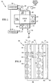
- a fuel cell power plant 36 which may embody the subject matter herein, includes a stack 37 of fuel cells 38 ( Fig. 2 ) which are shown disposed vertically, although they may be disposed horizontally.
- fuel is provided to a fuel inlet 42 and flows to the right in a first fuel pass, and then flows downwardly and to the left through a fuel outlet 47.
- the fuel may flow through a recycle pump (not shown) back to the fuel inlet, and may be periodically purged to ambient through a valve (not shown).
- Single pass, triple pass or other fuel flow configurations may be used.
- air is provided by a pump 52 to an air inlet 53, and the air flows upwardly through the oxidant reactant gas flow channels of the fuel cells 38.
- the air flows over a conduit 58 to a condenser 59, which in a vehicle may be a conventional radiator.
- the exit air is passed through an exhaust 62.
- the condensate from the condenser 59 may be accumulated in a reservoir 64, which is connected by a water return conduit 65 to a water inlet 66.
- the water then flows through passageways 83, 84 ( Fig.
- the passageways 83, 84 may terminate in a manifold 68, at which removal of gas from the passageways is provided through a vent, such as a micro vacuum pump 89, of the type utilized for a 37 liter (10 gallon) aquarium, which can be bought for several dollars, for the sole purpose of supplying sufficient head (water pressure) to ensure that the water level reaches the uppermost portions of the passageways in the stack 37.
- a vent such as a micro vacuum pump 89, of the type utilized for a 37 liter (10 gallon) aquarium, which can be bought for several dollars, for the sole purpose of supplying sufficient head (water pressure) to ensure that the water level reaches the uppermost portions of the passageways in the stack 37.
- the pump 89 does not cause any water flow through the vent manifold 68.
- the vent manifold 68 may be vented through a porous plug or other vent (not shown).
- one embodiment includes fuel cells 38, each of which comprises a conventional membrane electrode assembly 72, which includes an electrolyte with anode and cathode catalysts and gas diffusion layers on opposite sides of the electrolyte. It should be understood that the drawings herein are not at all to scale; no significance should be paid to the apparent different size of water passageways 83, 84 herein and those in the aforementioned patent.
- fuel reactant gas flows through horizontal channels 74 in a hydrophilic, porous substrate 75, which in this embodiment includes grooves which form a water passageway 83.
- a hydrophilic, porous oxidant reactant gas flow field plate 81 includes vertical air flow channels 82 and grooves which form a water passageway 84.
- the hydrophilic porous fuel reactant gas flow field plates 75 and the hydrophilic porous oxidant reactant gas flow field plates 81 are otherwise also referred to as "water transport plates".
- the fuel cells 38 of Fig. 2 include water permeable wicks 90 between the water passageways 83, 84.
- the wicks 90 may be thicker or thinner than the water transport plates 75, 81.
- the water permeable wicks 90 may comprise a suitable, readily available carbon paper, such as Toray H-060 which has been suitably treated, such as with tin, or a tin-containing compound or mixture, to render it sufficiently hydrophilic so to assure the desired permeability to water.
- a suitable, readily available carbon paper such as Toray H-060 which has been suitably treated, such as with tin, or a tin-containing compound or mixture, to render it sufficiently hydrophilic so to assure the desired permeability to water.
- the lands 90 provide additional surface area of the water transport plates which assist in transferring water.
- water transfers between the water passageways and the water transport plates only through the surfaces of the water passageways.
- the increase in surface area between available water, including that in the wicks 90 may be at least fourfold and perhaps as much as tenfold compared with the non-wick system of the aforementioned patent.
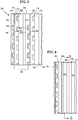
- Fig. 3 illustrates that the subject wicks 90 may be used with fuel cells having water passageways 84 in only the air flow field plates 81 , on the cathode side.
- the wick 90 could as well be used instead in fuel cells having water passageways 83 in only the fuel flow field plates.
- the surface is at least doubled, and may increase as much as fivefold compared with prior systems having only water passageways 83, 84 without any wicks 90.
- Fig. 4 is a view looking down on a section of Fig. 2 .
- the view is of two water passageways 83, 84, with the fuel channels 74 looking vertical and the air channels 82 looking horizontal.
- a first embodiment of the present invention utilizes flow through water passageways 83. Because the water is removed during shutdown in ambient regions where the surroundings of the fuel cell power plant may go below the freezing point of water, it is desirable to remove as much water as possible from the fuel cell stack. It has been found that in the embodiments of Figs. 2 and 3 , utilizing flow through water passageways 83 as illustrated in Fig. 5 , purging the water passageways 83, 84 with flow of air does not remove sufficient water. An excessive amount of water remains, particularly in the permeable wicks 90, after the water passageways have been mostly cleared by purging with air.
- the passageways are formed in an interdigitated fashion, as illustrated in Fig. 6 .
- the interdigitated water passageways comprise inlet water passageways 83a which are blocked at the outlet ends 101 thereof and the outlet passageways 83b that are blocked at the inlet ends 102 thereof, as is conventional with interdigitated flow fields. This increases the pressure sufficiently to drive air supplied to the passageways 83a through the water permeable wick 90 as well as through the porous hydrophilic water transport plate 75a thereby to increase water removal in accordance with a second aspect of the subject matter herein.
- FIG. 7 and 8 Another embodiment of the invention similar to Fig. 6 is shown in Figs. 7 and 8 .
- the outlet end 101 of the inlet passageways 83c are not completely closed off, but are provided with a partial enclosure 104 which is not drawn to any scale. The purpose of this is to ensure that any gas bubbles which may enter into the inlet water passageways 83c will not become trapped therein and thereby impede the flow of water into the adjacent ribs of the water transport plate 75b and the adjacent water permeable wick 90 (shown in Figs. 2 and 3 ).
- the outlet end 101 of the inlet water passageways 83d may simply have a small hole 106 therein, as illustrated in Fig. 9 .
- the hole 06 is larger than the pore size of the water transport plate 75c, to facilitate gas removal without lowering the water pressure in the inlet water passageways 83d to any meaningful extent.
Landscapes
- Engineering & Computer Science (AREA)
- Chemical & Material Sciences (AREA)
- Chemical Kinetics & Catalysis (AREA)
- Sustainable Development (AREA)
- Sustainable Energy (AREA)
- Manufacturing & Machinery (AREA)
- Life Sciences & Earth Sciences (AREA)
- Electrochemistry (AREA)
- General Chemical & Material Sciences (AREA)
- Fuel Cell (AREA)
- Combustion & Propulsion (AREA)
- Physics & Mathematics (AREA)
- Mechanical Engineering (AREA)
- Thermal Sciences (AREA)
- General Engineering & Computer Science (AREA)
Claims (4)
- Pile à combustible (38) comprenant :un assemblage d'électrodes à membrane (72) ayant un électrolyte avec des catalyseurs de cathode et d'anode disposés sur des côtés opposés de celui-ci et une couche de diffusion de gaz faisant face à chacune desdites couches de catalyseur;une plaque de champ d'écoulement de gaz réactif combustible (75) ayant des canaux d'écoulement de gaz réactif combustible (74) le long d'une première surface de celle-ci;une plaque de champ d'écoulement de gaz réactif oxydant (81) ayant des canaux d'écoulement de gaz réactif oxydant (82) sur une première surface de celle-ci;l'une ou les deux desdites plaques de champ d'écoulement étant poreuse et hydrophile;un passage d'eau (83, 84) disposé sur une seconde surface de ladite une ou desdites deux plaques de champ d'écoulement qui est à l'opposé de ladite première surface de celle(s)-ci;caractérisée par la combinaison de:une couche à effet de mèche hautement perméable à l'eau (90) disposée adjacente audit passage d'eau de ladite une ou desdites deux plaques de champ d'écoulement; etledit passage d'eau (83, 84) comprend un champ d'écoulement interdigité (83a, 83b).
- Pile à combustible (38) selon la revendication 1 caractérisée en outre en ce que:ledit champ d'écoulement interdigité (83a, 83b) présente des champs d'écoulement d'entrée (83c) avec des extrémités de sortie (101) qui sont seulement partiellement bloquées et configurées pour permettre au gaz de s'échapper.
- Pile à combustible (38) selon la revendication 2 caractérisée en outre en ce que:les extrémités de sortie (101) desdits champs d'écoulement d'entrée (83c) présentent une paroi partielle (104).
- Pile à combustible (38) selon la revendication 3 caractérisée en outre en ce que:les extrémités de sortie (101) desdits champs d'écoulement d'entrée (83d) présentent un trou (106) configuré pour permettre au gaz de s'échapper.
Applications Claiming Priority (1)
| Application Number | Priority Date | Filing Date | Title |
|---|---|---|---|
| PCT/US2010/002691 WO2012047184A1 (fr) | 2010-10-06 | 2010-10-06 | Piles à combustible refroidies par évaporation avec passages d'eau améliorés par des mèches |
Publications (3)
| Publication Number | Publication Date |
|---|---|
| EP2625738A1 EP2625738A1 (fr) | 2013-08-14 |
| EP2625738A4 EP2625738A4 (fr) | 2016-12-14 |
| EP2625738B1 true EP2625738B1 (fr) | 2018-01-17 |
Family
ID=45927980
Family Applications (1)
| Application Number | Title | Priority Date | Filing Date |
|---|---|---|---|
| EP10858210.7A Not-in-force EP2625738B1 (fr) | 2010-10-06 | 2010-10-06 | Piles à combustible refroidies par évaporation avec passages d'eau améliorés par des mèches |
Country Status (6)
| Country | Link |
|---|---|
| US (1) | US9455455B2 (fr) |
| EP (1) | EP2625738B1 (fr) |
| JP (1) | JP5680760B2 (fr) |
| KR (1) | KR101800056B1 (fr) |
| CN (1) | CN103503211B (fr) |
| WO (1) | WO2012047184A1 (fr) |
Families Citing this family (3)
| Publication number | Priority date | Publication date | Assignee | Title |
|---|---|---|---|---|
| DE102013218958A1 (de) * | 2013-09-20 | 2015-03-26 | Bayerische Motoren Werke Aktiengesellschaft | Abgasanlage und Kraftfahrzeug mit Abgasanlage |
| CN112968191B (zh) * | 2021-02-22 | 2022-06-21 | 西安交通大学 | 风冷燃料电池的阴极流场板结构和风冷燃料电池 |
| CN118073594A (zh) * | 2024-02-27 | 2024-05-24 | 同济大学 | 一种燃料电池用诱导冷凝强化排水极板流道结构 |
Family Cites Families (25)
| Publication number | Priority date | Publication date | Assignee | Title |
|---|---|---|---|---|
| JPH06231793A (ja) * | 1993-02-04 | 1994-08-19 | Mitsubishi Heavy Ind Ltd | 固体高分子電解質型燃料電池 |
| JPH07320753A (ja) * | 1994-05-27 | 1995-12-08 | Mitsubishi Heavy Ind Ltd | 固体高分子電解質膜型燃料電池 |
| US6780533B2 (en) * | 1999-12-17 | 2004-08-24 | Utc Fuel Cells, Llc | Fuel cell having interdigitated flow channels and water transport plates |
| US6586128B1 (en) | 2000-05-09 | 2003-07-01 | Ballard Power Systems, Inc. | Differential pressure fluid flow fields for fuel cells |
| US6416892B1 (en) * | 2000-07-28 | 2002-07-09 | Utc Fuel Cells, Llc | Interdigitated enthally exchange device for a fuel cell power plant |
| US6472095B2 (en) | 2000-12-29 | 2002-10-29 | Utc Fuel Cells, Llc | Hybrid fuel cell reactant flow fields |
| US6485857B2 (en) | 2000-12-29 | 2002-11-26 | Utc Fuel Cells, Llc | Fuel cell hybrid flow field humidification zone |
| GB2372143B (en) | 2001-02-12 | 2003-04-09 | Morgan Crucible Co | Flow field plate geometries for a fuel cell, including for a polymer electrolyte fuel cell |
| US6617068B2 (en) * | 2001-08-27 | 2003-09-09 | Utc Fuel Cells, Llc | Bi-zone water transport plate for a fuel cell |
| US6686084B2 (en) | 2002-01-04 | 2004-02-03 | Hybrid Power Generation Systems, Llc | Gas block mechanism for water removal in fuel cells |
| US6869709B2 (en) * | 2002-12-04 | 2005-03-22 | Utc Fuel Cells, Llc | Fuel cell system with improved humidification system |
| US6960404B2 (en) | 2003-02-27 | 2005-11-01 | General Motors Corporation | Evaporative cooled fuel cell |
| GB2409763B (en) * | 2003-12-31 | 2007-01-17 | Intelligent Energy Ltd | Water management in fuel cells |
| US7087330B2 (en) * | 2004-01-22 | 2006-08-08 | Utc Fuel Cells, Llc | Storing water in substrates for frozen, boot-strap start of fuel cells |
| US20100015483A1 (en) * | 2004-09-03 | 2010-01-21 | Yang Jefferson Ys | Reaction gas temperature and humidity regulating module for fuel cell stack |
| DE112005003309B4 (de) | 2004-12-29 | 2020-11-12 | Audi Ag | Verdampfungskühlung von Reaktantengas und betriebsmäßiger Gefrierschutz für Brennstoffzellenstromerzeuger |
| US7504170B2 (en) | 2004-12-29 | 2009-03-17 | Utc Power Corporation | Fuel cells evaporatively cooled with water carried in passageways |
| CN100592561C (zh) * | 2005-04-15 | 2010-02-24 | Utc电力公司 | 在冷冻启动过程中燃料电池堆中用于冷却和加湿的存留水 |
| KR101022111B1 (ko) | 2005-12-28 | 2011-03-17 | 유티씨 파워 코포레이션 | 부분적으로 폐쇄된 단부를 갖는 연료전지 유동장 채널 |
| EP1992038A4 (fr) | 2005-12-29 | 2011-01-19 | Utc Power Corp | Champ d'écoulement de pile à combustible stabilisé |
| US20070154744A1 (en) * | 2005-12-30 | 2007-07-05 | Darling Robert M | Fuel cell coolant bubble control |
| WO2008079126A1 (fr) * | 2006-12-22 | 2008-07-03 | Utc Power Corporation | Pile à combustible électrolyte ayant un effet de mèche de haute perméabilité destinée à un électrolyte condensé de retour |
| KR101258323B1 (ko) | 2008-04-18 | 2013-04-25 | 유티씨 파워 코포레이션 | 상호 맞물리는 유동장을 구비한 연료 전지 구성요소 |
| KR20100115391A (ko) | 2008-04-24 | 2010-10-27 | 유티씨 파워 코포레이션 | 연료 전지 내의 수분 분배를 관리하기 위한 흡수 층 |
| JP2010015868A (ja) * | 2008-07-04 | 2010-01-21 | Toshiba Fuel Cell Power Systems Corp | 燃料電池発電システム及び燃料電池発電方法 |
-
2010
- 2010-10-06 US US13/261,627 patent/US9455455B2/en active Active
- 2010-10-06 JP JP2013532755A patent/JP5680760B2/ja not_active Expired - Fee Related
- 2010-10-06 EP EP10858210.7A patent/EP2625738B1/fr not_active Not-in-force
- 2010-10-06 CN CN201080070524.8A patent/CN103503211B/zh active Active
- 2010-10-06 WO PCT/US2010/002691 patent/WO2012047184A1/fr not_active Ceased
- 2010-10-06 KR KR1020137010235A patent/KR101800056B1/ko not_active Expired - Fee Related
Non-Patent Citations (1)
| Title |
|---|
| None * |
Also Published As
| Publication number | Publication date |
|---|---|
| EP2625738A1 (fr) | 2013-08-14 |
| JP5680760B2 (ja) | 2015-03-04 |
| JP2013543224A (ja) | 2013-11-28 |
| CN103503211A (zh) | 2014-01-08 |
| CN103503211B (zh) | 2016-03-23 |
| US20130224622A1 (en) | 2013-08-29 |
| WO2012047184A1 (fr) | 2012-04-12 |
| KR20140009151A (ko) | 2014-01-22 |
| US9455455B2 (en) | 2016-09-27 |
| KR101800056B1 (ko) | 2017-11-21 |
| EP2625738A4 (fr) | 2016-12-14 |
Similar Documents
| Publication | Publication Date | Title |
|---|---|---|
| US7579098B2 (en) | Fuel cells evaporative reactant gas cooling and operational freeze prevention | |
| US20080038610A1 (en) | Fuel cells evaporative reactant gas cooling and operational freeze prevention | |
| US8182954B2 (en) | Full cells evaporative cooling and combined evaporative and sensible cooling | |
| US8771885B2 (en) | Circulation of biphase fuel cell coolant | |
| US12555804B2 (en) | Four-fluid bipolar plate for fuel cell | |
| US9455455B2 (en) | Evaporatively cooled fuel cells with water passageways enhanced by wicks | |
| JP2008305627A (ja) | 燃料電池スタックシステム | |
| JP2010129482A (ja) | 燃料電池用セパレータ、燃料電池スタック及び燃料電池システム | |
| JP5710527B2 (ja) | 燃料電池スタックおよび燃料電池システム | |
| EP1875544A1 (fr) | Retention d'eau dans un paquet de piles a combustible, a des fins de refroidissement et d'humidification au cours du demarrage a l'etat gele | |
| CN201440432U (zh) | 燃料电池的外部气体加湿装置 | |
| JP5474318B2 (ja) | 燃料電池スタック | |
| CN101071878A (zh) | 燃料电池的外部气体加湿装置 | |
| JP2005285694A (ja) | 固体高分子型燃料電池および燃料電池システム | |
| US20090155636A1 (en) | Water management for a fuel cell | |
| JP2005149827A (ja) | 燃料電池 | |
| JP2008098019A (ja) | 燃料電池用加湿器 |
Legal Events
| Date | Code | Title | Description |
|---|---|---|---|
| PUAI | Public reference made under article 153(3) epc to a published international application that has entered the european phase |
Free format text: ORIGINAL CODE: 0009012 |
|
| 17P | Request for examination filed |
Effective date: 20130503 |
|
| AK | Designated contracting states |
Kind code of ref document: A1 Designated state(s): AL AT BE BG CH CY CZ DE DK EE ES FI FR GB GR HR HU IE IS IT LI LT LU LV MC MK MT NL NO PL PT RO RS SE SI SK SM TR |
|
| DAX | Request for extension of the european patent (deleted) | ||
| RAP1 | Party data changed (applicant data changed or rights of an application transferred) |
Owner name: BALLARD POWER SYSTEMS INC. |
|
| RAP1 | Party data changed (applicant data changed or rights of an application transferred) |
Owner name: AUDI AG |
|
| RA4 | Supplementary search report drawn up and despatched (corrected) |
Effective date: 20161114 |
|
| RIC1 | Information provided on ipc code assigned before grant |
Ipc: H01M 8/04119 20160101ALI20161108BHEP Ipc: H01M 8/10 20060101ALI20161108BHEP Ipc: H01M 8/02 20060101ALI20161108BHEP Ipc: F25D 17/00 20060101ALI20161108BHEP Ipc: H01M 8/04 20060101AFI20161108BHEP |
|
| RIC1 | Information provided on ipc code assigned before grant |
Ipc: F25D 17/00 20060101ALI20170317BHEP Ipc: H01M 8/04 20160101AFI20170317BHEP Ipc: H01M 8/10 20160101ALI20170317BHEP Ipc: H01M 8/04119 20160101ALI20170317BHEP Ipc: H01M 8/02 20160101ALI20170317BHEP |
|
| GRAP | Despatch of communication of intention to grant a patent |
Free format text: ORIGINAL CODE: EPIDOSNIGR1 |
|
| INTG | Intention to grant announced |
Effective date: 20170509 |
|
| GRAJ | Information related to disapproval of communication of intention to grant by the applicant or resumption of examination proceedings by the epo deleted |
Free format text: ORIGINAL CODE: EPIDOSDIGR1 |
|
| INTC | Intention to grant announced (deleted) | ||
| GRAP | Despatch of communication of intention to grant a patent |
Free format text: ORIGINAL CODE: EPIDOSNIGR1 |
|
| INTG | Intention to grant announced |
Effective date: 20171027 |
|
| GRAS | Grant fee paid |
Free format text: ORIGINAL CODE: EPIDOSNIGR3 |
|
| GRAA | (expected) grant |
Free format text: ORIGINAL CODE: 0009210 |
|
| AK | Designated contracting states |
Kind code of ref document: B1 Designated state(s): AL AT BE BG CH CY CZ DE DK EE ES FI FR GB GR HR HU IE IS IT LI LT LU LV MC MK MT NL NO PL PT RO RS SE SI SK SM TR |
|
| REG | Reference to a national code |
Ref country code: GB Ref legal event code: FG4D |
|
| REG | Reference to a national code |
Ref country code: CH Ref legal event code: EP |
|
| REG | Reference to a national code |
Ref country code: IE Ref legal event code: FG4D |
|
| REG | Reference to a national code |
Ref country code: AT Ref legal event code: REF Ref document number: 964997 Country of ref document: AT Kind code of ref document: T Effective date: 20180215 |
|
| REG | Reference to a national code |
Ref country code: DE Ref legal event code: R096 Ref document number: 602010048171 Country of ref document: DE |
|
| REG | Reference to a national code |
Ref country code: NL Ref legal event code: MP Effective date: 20180117 |
|
| REG | Reference to a national code |
Ref country code: LT Ref legal event code: MG4D |
|
| REG | Reference to a national code |
Ref country code: AT Ref legal event code: MK05 Ref document number: 964997 Country of ref document: AT Kind code of ref document: T Effective date: 20180117 |
|
| PG25 | Lapsed in a contracting state [announced via postgrant information from national office to epo] |
Ref country code: NL Free format text: LAPSE BECAUSE OF FAILURE TO SUBMIT A TRANSLATION OF THE DESCRIPTION OR TO PAY THE FEE WITHIN THE PRESCRIBED TIME-LIMIT Effective date: 20180117 |
|
| PG25 | Lapsed in a contracting state [announced via postgrant information from national office to epo] |
Ref country code: FI Free format text: LAPSE BECAUSE OF FAILURE TO SUBMIT A TRANSLATION OF THE DESCRIPTION OR TO PAY THE FEE WITHIN THE PRESCRIBED TIME-LIMIT Effective date: 20180117 Ref country code: CY Free format text: LAPSE BECAUSE OF FAILURE TO SUBMIT A TRANSLATION OF THE DESCRIPTION OR TO PAY THE FEE WITHIN THE PRESCRIBED TIME-LIMIT Effective date: 20180117 Ref country code: LT Free format text: LAPSE BECAUSE OF FAILURE TO SUBMIT A TRANSLATION OF THE DESCRIPTION OR TO PAY THE FEE WITHIN THE PRESCRIBED TIME-LIMIT Effective date: 20180117 Ref country code: NO Free format text: LAPSE BECAUSE OF FAILURE TO SUBMIT A TRANSLATION OF THE DESCRIPTION OR TO PAY THE FEE WITHIN THE PRESCRIBED TIME-LIMIT Effective date: 20180417 Ref country code: ES Free format text: LAPSE BECAUSE OF FAILURE TO SUBMIT A TRANSLATION OF THE DESCRIPTION OR TO PAY THE FEE WITHIN THE PRESCRIBED TIME-LIMIT Effective date: 20180117 Ref country code: HR Free format text: LAPSE BECAUSE OF FAILURE TO SUBMIT A TRANSLATION OF THE DESCRIPTION OR TO PAY THE FEE WITHIN THE PRESCRIBED TIME-LIMIT Effective date: 20180117 |
|
| PG25 | Lapsed in a contracting state [announced via postgrant information from national office to epo] |
Ref country code: IS Free format text: LAPSE BECAUSE OF FAILURE TO SUBMIT A TRANSLATION OF THE DESCRIPTION OR TO PAY THE FEE WITHIN THE PRESCRIBED TIME-LIMIT Effective date: 20180517 Ref country code: BG Free format text: LAPSE BECAUSE OF FAILURE TO SUBMIT A TRANSLATION OF THE DESCRIPTION OR TO PAY THE FEE WITHIN THE PRESCRIBED TIME-LIMIT Effective date: 20180417 Ref country code: AT Free format text: LAPSE BECAUSE OF FAILURE TO SUBMIT A TRANSLATION OF THE DESCRIPTION OR TO PAY THE FEE WITHIN THE PRESCRIBED TIME-LIMIT Effective date: 20180117 Ref country code: RS Free format text: LAPSE BECAUSE OF FAILURE TO SUBMIT A TRANSLATION OF THE DESCRIPTION OR TO PAY THE FEE WITHIN THE PRESCRIBED TIME-LIMIT Effective date: 20180117 Ref country code: LV Free format text: LAPSE BECAUSE OF FAILURE TO SUBMIT A TRANSLATION OF THE DESCRIPTION OR TO PAY THE FEE WITHIN THE PRESCRIBED TIME-LIMIT Effective date: 20180117 Ref country code: SE Free format text: LAPSE BECAUSE OF FAILURE TO SUBMIT A TRANSLATION OF THE DESCRIPTION OR TO PAY THE FEE WITHIN THE PRESCRIBED TIME-LIMIT Effective date: 20180117 Ref country code: GR Free format text: LAPSE BECAUSE OF FAILURE TO SUBMIT A TRANSLATION OF THE DESCRIPTION OR TO PAY THE FEE WITHIN THE PRESCRIBED TIME-LIMIT Effective date: 20180418 Ref country code: PL Free format text: LAPSE BECAUSE OF FAILURE TO SUBMIT A TRANSLATION OF THE DESCRIPTION OR TO PAY THE FEE WITHIN THE PRESCRIBED TIME-LIMIT Effective date: 20180117 |
|
| REG | Reference to a national code |
Ref country code: DE Ref legal event code: R097 Ref document number: 602010048171 Country of ref document: DE |
|
| REG | Reference to a national code |
Ref country code: FR Ref legal event code: PLFP Year of fee payment: 9 |
|
| PG25 | Lapsed in a contracting state [announced via postgrant information from national office to epo] |
Ref country code: IT Free format text: LAPSE BECAUSE OF FAILURE TO SUBMIT A TRANSLATION OF THE DESCRIPTION OR TO PAY THE FEE WITHIN THE PRESCRIBED TIME-LIMIT Effective date: 20180117 Ref country code: EE Free format text: LAPSE BECAUSE OF FAILURE TO SUBMIT A TRANSLATION OF THE DESCRIPTION OR TO PAY THE FEE WITHIN THE PRESCRIBED TIME-LIMIT Effective date: 20180117 Ref country code: RO Free format text: LAPSE BECAUSE OF FAILURE TO SUBMIT A TRANSLATION OF THE DESCRIPTION OR TO PAY THE FEE WITHIN THE PRESCRIBED TIME-LIMIT Effective date: 20180117 Ref country code: AL Free format text: LAPSE BECAUSE OF FAILURE TO SUBMIT A TRANSLATION OF THE DESCRIPTION OR TO PAY THE FEE WITHIN THE PRESCRIBED TIME-LIMIT Effective date: 20180117 |
|
| PLBE | No opposition filed within time limit |
Free format text: ORIGINAL CODE: 0009261 |
|
| STAA | Information on the status of an ep patent application or granted ep patent |
Free format text: STATUS: NO OPPOSITION FILED WITHIN TIME LIMIT |
|
| PG25 | Lapsed in a contracting state [announced via postgrant information from national office to epo] |
Ref country code: DK Free format text: LAPSE BECAUSE OF FAILURE TO SUBMIT A TRANSLATION OF THE DESCRIPTION OR TO PAY THE FEE WITHIN THE PRESCRIBED TIME-LIMIT Effective date: 20180117 Ref country code: SK Free format text: LAPSE BECAUSE OF FAILURE TO SUBMIT A TRANSLATION OF THE DESCRIPTION OR TO PAY THE FEE WITHIN THE PRESCRIBED TIME-LIMIT Effective date: 20180117 Ref country code: SM Free format text: LAPSE BECAUSE OF FAILURE TO SUBMIT A TRANSLATION OF THE DESCRIPTION OR TO PAY THE FEE WITHIN THE PRESCRIBED TIME-LIMIT Effective date: 20180117 Ref country code: CZ Free format text: LAPSE BECAUSE OF FAILURE TO SUBMIT A TRANSLATION OF THE DESCRIPTION OR TO PAY THE FEE WITHIN THE PRESCRIBED TIME-LIMIT Effective date: 20180117 |
|
| 26N | No opposition filed |
Effective date: 20181018 |
|
| PG25 | Lapsed in a contracting state [announced via postgrant information from national office to epo] |
Ref country code: SI Free format text: LAPSE BECAUSE OF FAILURE TO SUBMIT A TRANSLATION OF THE DESCRIPTION OR TO PAY THE FEE WITHIN THE PRESCRIBED TIME-LIMIT Effective date: 20180117 |
|
| REG | Reference to a national code |
Ref country code: CH Ref legal event code: PL |
|
| REG | Reference to a national code |
Ref country code: BE Ref legal event code: MM Effective date: 20181031 |
|
| PG25 | Lapsed in a contracting state [announced via postgrant information from national office to epo] |
Ref country code: MC Free format text: LAPSE BECAUSE OF FAILURE TO SUBMIT A TRANSLATION OF THE DESCRIPTION OR TO PAY THE FEE WITHIN THE PRESCRIBED TIME-LIMIT Effective date: 20180117 Ref country code: LU Free format text: LAPSE BECAUSE OF NON-PAYMENT OF DUE FEES Effective date: 20181006 |
|
| REG | Reference to a national code |
Ref country code: IE Ref legal event code: MM4A |
|
| PG25 | Lapsed in a contracting state [announced via postgrant information from national office to epo] |
Ref country code: BE Free format text: LAPSE BECAUSE OF NON-PAYMENT OF DUE FEES Effective date: 20181031 Ref country code: LI Free format text: LAPSE BECAUSE OF NON-PAYMENT OF DUE FEES Effective date: 20181031 Ref country code: CH Free format text: LAPSE BECAUSE OF NON-PAYMENT OF DUE FEES Effective date: 20181031 |
|
| PG25 | Lapsed in a contracting state [announced via postgrant information from national office to epo] |
Ref country code: IE Free format text: LAPSE BECAUSE OF NON-PAYMENT OF DUE FEES Effective date: 20181006 |
|
| PG25 | Lapsed in a contracting state [announced via postgrant information from national office to epo] |
Ref country code: MT Free format text: LAPSE BECAUSE OF NON-PAYMENT OF DUE FEES Effective date: 20181006 |
|
| PG25 | Lapsed in a contracting state [announced via postgrant information from national office to epo] |
Ref country code: TR Free format text: LAPSE BECAUSE OF FAILURE TO SUBMIT A TRANSLATION OF THE DESCRIPTION OR TO PAY THE FEE WITHIN THE PRESCRIBED TIME-LIMIT Effective date: 20180117 |
|
| PG25 | Lapsed in a contracting state [announced via postgrant information from national office to epo] |
Ref country code: PT Free format text: LAPSE BECAUSE OF FAILURE TO SUBMIT A TRANSLATION OF THE DESCRIPTION OR TO PAY THE FEE WITHIN THE PRESCRIBED TIME-LIMIT Effective date: 20180117 |
|
| PG25 | Lapsed in a contracting state [announced via postgrant information from national office to epo] |
Ref country code: HU Free format text: LAPSE BECAUSE OF FAILURE TO SUBMIT A TRANSLATION OF THE DESCRIPTION OR TO PAY THE FEE WITHIN THE PRESCRIBED TIME-LIMIT; INVALID AB INITIO Effective date: 20101006 Ref country code: MK Free format text: LAPSE BECAUSE OF NON-PAYMENT OF DUE FEES Effective date: 20180117 |
|
| PGFP | Annual fee paid to national office [announced via postgrant information from national office to epo] |
Ref country code: GB Payment date: 20211023 Year of fee payment: 12 Ref country code: DE Payment date: 20211031 Year of fee payment: 12 |
|
| PGFP | Annual fee paid to national office [announced via postgrant information from national office to epo] |
Ref country code: FR Payment date: 20211026 Year of fee payment: 12 |
|
| REG | Reference to a national code |
Ref country code: DE Ref legal event code: R119 Ref document number: 602010048171 Country of ref document: DE |
|
| GBPC | Gb: european patent ceased through non-payment of renewal fee |
Effective date: 20221006 |
|
| P01 | Opt-out of the competence of the unified patent court (upc) registered |
Effective date: 20230530 |
|
| PG25 | Lapsed in a contracting state [announced via postgrant information from national office to epo] |
Ref country code: FR Free format text: LAPSE BECAUSE OF NON-PAYMENT OF DUE FEES Effective date: 20221031 Ref country code: DE Free format text: LAPSE BECAUSE OF NON-PAYMENT OF DUE FEES Effective date: 20230503 |
|
| PG25 | Lapsed in a contracting state [announced via postgrant information from national office to epo] |
Ref country code: GB Free format text: LAPSE BECAUSE OF NON-PAYMENT OF DUE FEES Effective date: 20221006 |