EP2626171B1 - Magasin destiné à recevoir des outils de traitement et/ou agrégats de traitement - Google Patents
Magasin destiné à recevoir des outils de traitement et/ou agrégats de traitement Download PDFInfo
- Publication number
- EP2626171B1 EP2626171B1 EP13154170.8A EP13154170A EP2626171B1 EP 2626171 B1 EP2626171 B1 EP 2626171B1 EP 13154170 A EP13154170 A EP 13154170A EP 2626171 B1 EP2626171 B1 EP 2626171B1
- Authority
- EP
- European Patent Office
- Prior art keywords
- magazine
- circumference
- holding device
- tools
- receptacles
- Prior art date
- Legal status (The legal status is an assumption and is not a legal conclusion. Google has not performed a legal analysis and makes no representation as to the accuracy of the status listed.)
- Active
Links
Images

Classifications
-
- B—PERFORMING OPERATIONS; TRANSPORTING
- B23—MACHINE TOOLS; METAL-WORKING NOT OTHERWISE PROVIDED FOR
- B23Q—DETAILS, COMPONENTS, OR ACCESSORIES FOR MACHINE TOOLS, e.g. ARRANGEMENTS FOR COPYING OR CONTROLLING; MACHINE TOOLS IN GENERAL CHARACTERISED BY THE CONSTRUCTION OF PARTICULAR DETAILS OR COMPONENTS; COMBINATIONS OR ASSOCIATIONS OF METAL-WORKING MACHINES, NOT DIRECTED TO A PARTICULAR RESULT
- B23Q3/00—Devices holding, supporting, or positioning work or tools, of a kind normally removable from the machine
- B23Q3/155—Arrangements for automatic insertion or removal of tools, e.g. combined with manual handling
- B23Q3/157—Arrangements for automatic insertion or removal of tools, e.g. combined with manual handling of rotary tools
- B23Q3/15713—Arrangements for automatic insertion or removal of tools, e.g. combined with manual handling of rotary tools a transfer device taking a single tool from a storage device and inserting it in a spindle
- B23Q3/1572—Arrangements for automatic insertion or removal of tools, e.g. combined with manual handling of rotary tools a transfer device taking a single tool from a storage device and inserting it in a spindle the storage device comprising rotating or circulating storing means
- B23Q3/15722—Rotary discs or drums
-
- B—PERFORMING OPERATIONS; TRANSPORTING
- B23—MACHINE TOOLS; METAL-WORKING NOT OTHERWISE PROVIDED FOR
- B23Q—DETAILS, COMPONENTS, OR ACCESSORIES FOR MACHINE TOOLS, e.g. ARRANGEMENTS FOR COPYING OR CONTROLLING; MACHINE TOOLS IN GENERAL CHARACTERISED BY THE CONSTRUCTION OF PARTICULAR DETAILS OR COMPONENTS; COMBINATIONS OR ASSOCIATIONS OF METAL-WORKING MACHINES, NOT DIRECTED TO A PARTICULAR RESULT
- B23Q3/00—Devices holding, supporting, or positioning work or tools, of a kind normally removable from the machine
- B23Q3/155—Arrangements for automatic insertion or removal of tools, e.g. combined with manual handling
- B23Q3/1552—Arrangements for automatic insertion or removal of tools, e.g. combined with manual handling parts of devices for automatically inserting or removing tools
- B23Q3/15526—Storage devices; Drive mechanisms therefor
- B23Q3/15539—Plural magazines, e.g. involving tool transfer from one magazine to another
Definitions
- the invention relates to a magazine for accommodating machining tools and / or machining units for a machining device, in particular a machining center for machining workpieces, which are preferably at least partially made of wood, Holzwerstoffen, plastic or the like, according to the preamble of claim 1.
- a tray changer is preferably used as a magazine to store tools for a tool change.
- a tool from a tool spindle is created in the plate changer and another tool used from this plate change in the spindle.
- a typical plate changer is characterized by tool holders on the plate circumference. Plate changers offer a simple system for storing tools, with the distance between them depending on the size of the tool and the number of tools determine the diameter of the plate. For example, 10-fold, 12-fold, 14-fold and 18-fold plate changers are used.
- Such plate changers have proven to be a simple and inexpensive magazine for holding tools. However, with respect to the number of tools always higher requirements, so that the number of tool holders must be increased. However, the diameter of the plate and thus the diameter of the plate can not be made arbitrarily large due to the rigidity and the positioning accuracy of the drive. Therefore, it must then be avoided on an alternative recording option for tools.
- This can be a chain changer with converter, whereby the converter serves for preparing the tools for the next tool change parallel to the main time.
- the use of a derailleur is associated with the disadvantages that they are much more expensive and expensive than Tellerwechsler.
- a machine tool with a machine frame with a rotatably driven tool spindle provided with a workpiece clamping device and with a magazine.
- the magazine has an outer magazine wheel and an inner magazine wheel coaxially disposed therein, the magazine wheels being independently positionable independently of each other.
- the invention is based on the idea to efficiently use the space occupied by a plate changer or other magazine space.
- the magazine for receiving processing tools and / or processing units has a first and second receiving device with corresponding first and second receptacles for processing tools and / or Processing units, wherein the first and second receptacles are respectively arranged at first and second circumferences, wherein the second circumference is smaller than the first circumference and the second circumference lies within the first circumference, when the receiving devices are viewed from a direction perpendicular to a level is one of the perimeters.
- the invention proves to be particularly advantageous if smaller tools are received on the second circumference of the second receiving device. Overall, this leads to the fact that an enlargement of the plate for receiving additional tools is not necessary, since a second receiving device is present, which can accommodate the other tools. This ensures that space-saving and cost, the capacity of a plate changer is increased. For example, it is initially possible to dispense with avoiding a chain changer. At the same time a simple and reliable access to the tools is guaranteed.
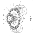
- a magazine 1 according to the present invention is in Fig. 1 shown schematically in a plan view.
- This magazine 1 in the present embodiment is a tray changer for accommodating machining tools and / or machining units (hereinafter simply “tools") 2 for a machining apparatus or a machining center (not shown) for machining workpieces , which preferably at least partially made of wood materials, plastic or the like, such as furniture fronts, countertops and the like.
- tools machining tools and / or machining units
- machining workpieces which preferably at least partially made of wood materials, plastic or the like, such as furniture fronts, countertops and the like.
- the magazine 1 initially has a first receiving device 3 with a plurality of first receptacles 4 in which the tools 2 are received.
- the tools 2 are mounted in these receptacles 4 hanging down.
- These first receptacles 4 are arranged on a first circumference 5.
- this scope is understood to mean the edge region of the receiving device.
- the magazine 1 has a second receiving device 30 with a plurality of second receptacles 40, which also receive tools 2. These second receptacles 40 are arranged on a second circumference 50 which is smaller than the first circumference 5.
- the circumference is to be understood as meaning the edge region of the receiving device.
- the first 3 and second 30 receiving means are arranged such that the periphery 40 of the second receiving means 30 is within the periphery 4 of the first receiving means 3 when the magazine is viewed from a direction perpendicular to the plane of one of the peripheries, such as in Fig. 1 shown.
- the planes of the first and second circumferences are the planes defined by the first and second circumferences and need not necessarily be parallel to each other, but are preferably.
- the second circumference 50 is to be selected. There will be a compromise between maximum space savings, accessibility of the tools and the effort of technical implementation.
- the recording devices - regardless of the number - Have a variety of geometries, including polygonal shapes, such as rectangular to polygonal.
- the inventive design results in that an enlargement of the plate circumference for receiving additional tools is not necessary, since a second receiving device is present, which can accommodate the other tools. This ensures that the capacity of a tool magazine is increased in a space-saving and cost-effective manner. At the same time a simple and reliable access to the tools is guaranteed.
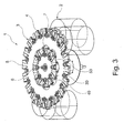
- the second receiving device 30 is arranged offset with respect to the first receiving device 3 in a direction perpendicular to a plane of the first 5 or second 50 circumference of the first 3 or second 30 receiving device.
- the second receiving device 30 is offset from the first receiving device 3 at a predetermined distance, preferably offset upwards, such as in Fig. 2 shown. This distance is determined, for example, in view of the length of the tools 2 in the second receiving device 30.
- the second circumference 50 of the second receiving device 30 should preferably be dimensioned such that the tools 2 in the second receptacles 40 does not hinder the accessibility of the tools 2 in the first receiving unit 3 arranged thereunder.
- the second receiving device 30 is movable relative to the first receiving device 3 in the direction which is perpendicular to a plane of the first 5 or second 50 perimeter of the first 3 or second 30 receiving device.
- the second receiving device 30 is moved upward.
- the second receiving device 30 can be moved in such a way that the tools 2 in the first 4 and second 40 receptacles can easily be reached and exchanged by the spindle.
- the possibility for saving space is further improved because, for example, if no change of the tools 2 is carried out, which are received in the second receiving device 30, the distance of the second receiving device 30 to the first receiving device 3 less may be when he after extension of the receiving device 30, eg when a tool change is.
- the second receiving device 30 can be brought to an approximately same level to this first receiving device 3, so that, while no tool 2 of the second receiving device 30 is changed, the tools 2 in the receptacles 40 of the second Receiving device 30 are located in the space under the first receiving device 3, which is not occupied by the tools 2, which are received in the receptacles 4 of the first receiving device 3.
- recesses 7 are preferably provided in the first receiving device 3, in which the tools 2 can extend in the second receptacles 40.
- the second circumference 50 should then be designed so that the tools 2 in the second receptacles 40 lie within the area of the first receiving device 3, below which there are no tools 2 in the first receptacles 4.
- first and the second receiving means 3, 30 can both be movable, preferably independently of one another.
- the first 3 and second 30 receiving means may be arranged without clearance with respect to a direction perpendicular to a plane of the first 5 or second 50 circumference of the first 3 or second 30 receiving means. This is to be understood that the first receiving device 3 and the second receiving device 30 abut each other with respect to the direction perpendicular to a plane of the circumference of one of the receiving devices.
- the first receiving device 3 is designed such that tools 2 can be removed from the second receiving device 30.
- the first receiving device 3 can have recesses 7 into which the tools 2 can extend, which are received in the second receptacles 40 of the second receiving device 30. With appropriate design of these recesses 7 then the spindle units can remove the tools 2 from the second receiving device 30. This allows a technically simple solution with maximum space savings.
- the magazine 1 has a first center of the first receptacle 3 defined by the first perimeter 5 and a second center of the second receptacle 30 defined by the second perimeter 50 is defined.
- the first and second centers may be offset only in the direction perpendicular to the planes of the first 5 and second 50 perimeters of the first 3 and second 30 receiving means. This results in easier accessibility of the tools 2 for the spindle when changing tools 2.
- first 5 and second 50 circumference as a circle circumference.
- first 3 and second 30 receiving device may be arranged concentrically. Due to the circular design of the circumferences the best approachability for the spindle is made possible. In addition, the space savings can be maximized.
- an opening of the receptacles in a direction which is radial to the receiving device is defined by an angle ⁇ , as in Fig. 1 shown, which is shown here for example for a second receptacle 40.
- the opening angle of the recordings can thus be described by two straight lines which indicate the radius of the receiving device.
- the first receptacles 4 of the first receiving device 3 may be formed radially.
- the present invention is designed with recordings which have no offset. This means that the opening of the receptacles is formed radially to the receiving device. As a result, the approachability is improved by the spindle and allows easier accessibility.
- a magazine 1 in particular a plate changer, in a processing device (not shown), in particular a machining center (not shown) for the machining of workpieces (not shown) used, which preferably at least partially made of wood, Holzwerstoffen, plastic or the like.
- a worktable (not shown) is used for clamping the workpieces to be processed.
- a beam-shaped guide device (not shown) is arranged such that it extends at least partially over the clamping table. This can also be constructed as a portal or similar. The worktable and the bar-shaped guide device are movable relative to one another in at least one direction.
- a spindle unit (not shown) is arranged movable.
- a rotation axis 6 of the magazine 1 and a rotation axis of the spindle unit are arranged at the same distance from the guide device.
- the first 3 and second receiving means 30 may be rotatable about a common axis of rotation 6.
- the first and second receiving device can either be rotated independently of each other or rotated together. As a result, an easy driving and easy changing the tools 2 is possible.
- the tools 2 are arranged hanging down in the receptacles. Likewise, the tools 2 can also be accommodated “upright” up there. Furthermore, it has been stated that the second receiving device 30 is displaced upward or is movable. Likewise, it is also possible that a relocation or procedure is down.
- the inventive concept also includes other types of magazines such as chain changer, which are used to store tools 2 and in which a space savings can be achieved by an inventive arrangement.
Landscapes
- Engineering & Computer Science (AREA)
- Mechanical Engineering (AREA)
- Automatic Tool Replacement In Machine Tools (AREA)
Claims (11)
- Magasin (1) destiné à recevoir des outils d'usinage et/ou des agrégats d'usinage (2) pour une installation d'usinage, en particulier pour un centre d'usinage pour l'usinage de pièces préférentiellement au moins partiellement en bois, matériaux ligneux, matières synthétiques ou similaires, comportant
un premier dispositif de réception (3) avec plusieurs premiers logements (4) pour des outils d'usinage et/ou des agrégats d'usinage (2),
lesdits premiers logements (4) étant disposés sur une première périphérie (5),
ledit magasin (1) comportant en outre un deuxième dispositif de réception (30) avec plusieurs deuxièmes logements (40) pour des outils d'usinage et/ou des agrégats d'usinage (2),
les deuxièmes logements (40) étant disposés sur une deuxième périphérie (50) inférieure à la première périphérie (5), et
le premier et le deuxième dispositif de réception (3, 30) étant disposés de sorte que, vue dans une direction perpendiculaire au plan de la périphérie (5, 50) de la première ou de la deuxième unité de réception (3, 30), la deuxième périphérie (50) est comprise à l'intérieur de la première périphérie (5),
caractérisé en ce que
le premier dispositif de réception (3) présente des évidements (7) où peuvent s'étendre des outils (2) reçus dans des logements (40) du deuxième dispositif de réception (30). - Magasin (1) selon la revendication 1, où le deuxième dispositif de réception (30) est décalé, préférentiellement vers le haut, par rapport au premier dispositif de réception (3) dans une direction perpendiculaire au plan de la périphérie (5, 50) du premier ou du deuxième dispositif de réception (3, 30).
- Magasin (1) selon la revendication 1, où le deuxième dispositif de réception (30) est déplaçable, préférentiellement vers le haut, par rapport au premier dispositif de réception (3) dans une direction perpendiculaire au plan de la périphérie (5, 50) du premier ou du deuxième dispositif de réception (3, 30).
- Magasin (1) selon l'une des revendications précédentes, où le premier et le deuxième dispositif de réception (3, 30) sont déplaçables, préférentiellement indépendamment l'un de l'autre.
- Magasin (1) selon l'une des revendications précédentes, où le premier et le deuxième dispositif de réception (3, 30) ne sont pas espacés dans une direction perpendiculaire au plan de la périphérie (5, 50) du premier ou du deuxième dispositif de réception (3, 30), et où le premier dispositif de réception (3) est réalisé de manière à pouvoir prélever des outils d'usinage et/ou des agrégats d'usinage (2) du deuxième dispositif de réception (30).
- Magasin (1) selon l'une des revendications précédentes, où le premier dispositif de réception (3) présente un premier point central défini par la première périphérie (5), le deuxième dispositif de réception (30) un deuxième point central défini par la deuxième périphérie (50), et en ce que lesdits premier et deuxième points centraux ne peuvent être décalés que dans la direction perpendiculaire aux plans de la première et de la deuxième périphérie (5, 50) du premier et du deuxième dispositif de réception (3, 30).
- Magasin (1) selon l'une des revendications précédentes, où la première et la deuxième périphérie (5, 50) sont des circonférences de cercle.
- Magasin (1) selon la revendication 7, où les ouvertures des logements (4, 40) d'au moins un dispositif de réception (3, 30) sont ménagées radialement au dispositif de réception (3, 30).
- Magasin (1) selon l'une des revendications précédentes, où les logements (4, 40) d'au moins un dispositif de réception (3, 30) ne sont pas coudés.
- Installation d'usinage, en particulier centre d'usinage pour l'usinage de pièces préférentiellement au moins partiellement en bois, matériaux ligneux, matières synthétiques ou similaires, comportant :une table porte-pièce pour le chargement des pièces à usiner,une dispositif de guidage en forme de barre qui s'étend au moins partiellement au-dessus de la table porte-pièce, ladite table porte-pièce et le dispositif de guidage en forme de barre étant déplaçables l'une par rapport à l'autre dans au moins une direction, etau moins une unité de broche, disposée de manière à être mobile sur le dispositif de guidage,caractérisée par un magasin (1) selon l'une des revendications 1 à 9.
- Installation d'usinage selon la revendication 10, où un axe de rotation (6) du magasin (1) et un axe de rotation de l'unité de broche sont pareillement espacés du dispositif de guidage.
Applications Claiming Priority (1)
| Application Number | Priority Date | Filing Date | Title |
|---|---|---|---|
| DE102012201776A DE102012201776A1 (de) | 2012-02-07 | 2012-02-07 | Magazin zur Aufnahme von Bearbeitungswerkzeugen und/oder Bearbeitungsaggregaten |
Publications (2)
| Publication Number | Publication Date |
|---|---|
| EP2626171A1 EP2626171A1 (fr) | 2013-08-14 |
| EP2626171B1 true EP2626171B1 (fr) | 2014-01-29 |
Family
ID=47722027
Family Applications (1)
| Application Number | Title | Priority Date | Filing Date |
|---|---|---|---|
| EP13154170.8A Active EP2626171B1 (fr) | 2012-02-07 | 2013-02-06 | Magasin destiné à recevoir des outils de traitement et/ou agrégats de traitement |
Country Status (3)
| Country | Link |
|---|---|
| EP (1) | EP2626171B1 (fr) |
| DE (1) | DE102012201776A1 (fr) |
| ES (1) | ES2459319T3 (fr) |
Cited By (3)
| Publication number | Priority date | Publication date | Assignee | Title |
|---|---|---|---|---|
| DE102014211566A1 (de) | 2014-06-17 | 2015-12-17 | Homag Holzbearbeitungssysteme Gmbh | Bearbeitungszentrum zum Bearbeiten von Werkstücken |
| CN107000146A (zh) * | 2014-09-19 | 2017-08-01 | 豪迈股份公司 | 用于加工刀具的夹持设备、储存系统以及方法 |
| WO2019135561A1 (fr) * | 2018-01-03 | 2019-07-11 | 두산공작기계 주식회사 | Magasin d'outils d'une machine-outil |
Families Citing this family (4)
| Publication number | Priority date | Publication date | Assignee | Title |
|---|---|---|---|---|
| CN104526431B (zh) * | 2015-01-03 | 2016-09-21 | 巨轮智能装备股份有限公司 | 双层圆盘式刀库装置 |
| CN106975957B (zh) * | 2017-05-15 | 2023-08-15 | 北京精雕科技集团有限公司 | 一种双层刀库 |
| CN113752063B (zh) * | 2021-09-30 | 2025-01-17 | 齐重数控装备股份有限公司 | 一种用于五轴数控加工设备的车铣复合双刀库装置及工作方法 |
| EP4703083A1 (fr) | 2024-08-26 | 2026-03-04 | Paolino Bacci S.R.L. | Magasin d'outils pour un centre d'usinage et centre d'usinage comprenant ledit magasin |
Family Cites Families (9)
| Publication number | Priority date | Publication date | Assignee | Title |
|---|---|---|---|---|
| US3300856A (en) * | 1964-02-14 | 1967-01-31 | Giddings & Lewis | Machine tool with automatic tool changing apparatus |
| US3458924A (en) * | 1967-08-23 | 1969-08-05 | Heald Machine Co | Machine tool |
| CH568130A5 (fr) * | 1974-02-04 | 1975-10-31 | Knaus Reto | |
| US4087901A (en) * | 1976-08-16 | 1978-05-09 | Kearney & Trecker Corporation | Tool change mechanism for machine tools |
| FR2515948A1 (fr) * | 1981-11-12 | 1983-05-13 | Pasquier Roger | Magasin-presentoir pour outils |
| IT8222028U1 (it) * | 1982-05-28 | 1983-11-28 | M C M S P A | Dispositivo per il cambio di utensili su centri di lavoro con magazzino portautensili di elevata capienza. |
| US4590662A (en) * | 1982-09-03 | 1986-05-27 | Makino Milling Machine Co., Ltd. | Tool changing machine of machine tool |
| SU1715545A1 (ru) * | 1990-01-15 | 1992-02-28 | Бишкекский политехнический институт | Устройство дл автоматической смены инструмента |
| DE102008005937B3 (de) * | 2008-01-24 | 2009-06-18 | Haas Schleifmaschinen Gmbh | Werkzeugmaschine |
-
2012
- 2012-02-07 DE DE102012201776A patent/DE102012201776A1/de not_active Ceased
-
2013
- 2013-02-06 ES ES13154170.8T patent/ES2459319T3/es active Active
- 2013-02-06 EP EP13154170.8A patent/EP2626171B1/fr active Active
Cited By (5)
| Publication number | Priority date | Publication date | Assignee | Title |
|---|---|---|---|---|
| DE102014211566A1 (de) | 2014-06-17 | 2015-12-17 | Homag Holzbearbeitungssysteme Gmbh | Bearbeitungszentrum zum Bearbeiten von Werkstücken |
| EP2957382A1 (fr) | 2014-06-17 | 2015-12-23 | Homag Holzbearbeitungssysteme GmbH | Centre d'usinage de pièces |
| CN107000146A (zh) * | 2014-09-19 | 2017-08-01 | 豪迈股份公司 | 用于加工刀具的夹持设备、储存系统以及方法 |
| WO2019135561A1 (fr) * | 2018-01-03 | 2019-07-11 | 두산공작기계 주식회사 | Magasin d'outils d'une machine-outil |
| US11433497B2 (en) | 2018-01-03 | 2022-09-06 | Doosan Machine Tools Co., Ltd. | Tool magazine of machine tool |
Also Published As
| Publication number | Publication date |
|---|---|
| EP2626171A1 (fr) | 2013-08-14 |
| ES2459319T3 (es) | 2014-05-09 |
| DE102012201776A1 (de) | 2013-08-08 |
Similar Documents
| Publication | Publication Date | Title |
|---|---|---|
| EP2626171B1 (fr) | Magasin destiné à recevoir des outils de traitement et/ou agrégats de traitement | |
| EP2899599B1 (fr) | Support de pièce pour une fraiseuse | |
| DE1952050C3 (de) | Revolver-Drehautomat | |
| EP2915622A1 (fr) | Machine d'usinage, en particulier rectifieuse, avec un magasin d'outils rotatif | |
| DE3006650A1 (de) | Maschine zum funkenerosionsbearbeiten von werkstuecken | |
| EP3291943B1 (fr) | Machine-outil | |
| WO2007137698A1 (fr) | Machine-outil | |
| DE4203656C2 (de) | Vorrichtung zur Herstellung von Axialnuten an Läuferscheiben eines Turbinenläufers | |
| EP2957382B1 (fr) | Centre d'usinage de pièces | |
| DE2828536A1 (de) | Werkzeugmaschine | |
| DE2129515C3 (de) | Schalttellermaschine | |
| EP1977856A1 (fr) | Machine-outil | |
| DE3530479A1 (de) | Kombinierte dreh- und tiefbohrmaschine | |
| EP3311967A1 (fr) | Dispositif à travailler le bois | |
| DE102005031933B4 (de) | Werkzeugmaschine und Verfahren zur Fertigung | |
| DE102012207093A1 (de) | Bearbeitungsvorrichtung mit Werkzeugwechselanordnung, insbesondere Kettenwechsler | |
| DE3109198C2 (de) | Fräsmaschine zum Fräsen von Nuten in Bohrungswandungen von Werkstücken | |
| EP0744255A2 (fr) | Dispositif pour découper des troncs d'arbres et tête de fraisage pour ce dispositif | |
| DE4109877C2 (fr) | ||
| EP0310937A2 (fr) | Corps de serrage pour la fixation de pièces à usiner | |
| DE20307225U1 (de) | Werkzeugmaschine | |
| DE2322825A1 (de) | Schneidwerkzeug und verfahren zur anformung der schneidkanten desselben | |
| DE19715771C1 (de) | Außenräummaschine | |
| DE102015002756B4 (de) | Schneidplattenhalter und Schneidplattensystem | |
| DE400918C (de) | Fraesmaschine zum gleichzeitigen Nutenfraesen und Hinterfraesen von Spiralbohrern, Reibahlen u. dgl. |
Legal Events
| Date | Code | Title | Description |
|---|---|---|---|
| PUAI | Public reference made under article 153(3) epc to a published international application that has entered the european phase |
Free format text: ORIGINAL CODE: 0009012 |
|
| AK | Designated contracting states |
Kind code of ref document: A1 Designated state(s): AL AT BE BG CH CY CZ DE DK EE ES FI FR GB GR HR HU IE IS IT LI LT LU LV MC MK MT NL NO PL PT RO RS SE SI SK SM TR |
|
| AX | Request for extension of the european patent |
Extension state: BA ME |
|
| 17P | Request for examination filed |
Effective date: 20130723 |
|
| RBV | Designated contracting states (corrected) |
Designated state(s): AL AT BE BG CH CY CZ DE DK EE ES FI FR GB GR HR HU IE IS IT LI LT LU LV MC MK MT NL NO PL PT RO RS SE SI SK SM TR |
|
| GRAP | Despatch of communication of intention to grant a patent |
Free format text: ORIGINAL CODE: EPIDOSNIGR1 |
|
| INTG | Intention to grant announced |
Effective date: 20130911 |
|
| GRAS | Grant fee paid |
Free format text: ORIGINAL CODE: EPIDOSNIGR3 |
|
| GRAA | (expected) grant |
Free format text: ORIGINAL CODE: 0009210 |
|
| AK | Designated contracting states |
Kind code of ref document: B1 Designated state(s): AL AT BE BG CH CY CZ DE DK EE ES FI FR GB GR HR HU IE IS IT LI LT LU LV MC MK MT NL NO PL PT RO RS SE SI SK SM TR |
|
| REG | Reference to a national code |
Ref country code: GB Ref legal event code: FG4D Free format text: NOT ENGLISH |
|
| REG | Reference to a national code |
Ref country code: CH Ref legal event code: EP |
|
| REG | Reference to a national code |
Ref country code: AT Ref legal event code: REF Ref document number: 651383 Country of ref document: AT Kind code of ref document: T Effective date: 20140215 |
|
| REG | Reference to a national code |
Ref country code: IE Ref legal event code: FG4D Free format text: LANGUAGE OF EP DOCUMENT: GERMAN |
|
| REG | Reference to a national code |
Ref country code: DE Ref legal event code: R096 Ref document number: 502013000005 Country of ref document: DE Effective date: 20140306 |
|
| REG | Reference to a national code |
Ref country code: ES Ref legal event code: FG2A Ref document number: 2459319 Country of ref document: ES Kind code of ref document: T3 Effective date: 20140509 |
|
| REG | Reference to a national code |
Ref country code: NL Ref legal event code: VDEP Effective date: 20140129 |
|
| REG | Reference to a national code |
Ref country code: LT Ref legal event code: MG4D |
|
| PG25 | Lapsed in a contracting state [announced via postgrant information from national office to epo] |
Ref country code: LT Free format text: LAPSE BECAUSE OF FAILURE TO SUBMIT A TRANSLATION OF THE DESCRIPTION OR TO PAY THE FEE WITHIN THE PRESCRIBED TIME-LIMIT Effective date: 20140129 Ref country code: IS Free format text: LAPSE BECAUSE OF FAILURE TO SUBMIT A TRANSLATION OF THE DESCRIPTION OR TO PAY THE FEE WITHIN THE PRESCRIBED TIME-LIMIT Effective date: 20140529 Ref country code: NO Free format text: LAPSE BECAUSE OF FAILURE TO SUBMIT A TRANSLATION OF THE DESCRIPTION OR TO PAY THE FEE WITHIN THE PRESCRIBED TIME-LIMIT Effective date: 20140429 |
|
| PG25 | Lapsed in a contracting state [announced via postgrant information from national office to epo] |
Ref country code: PT Free format text: LAPSE BECAUSE OF FAILURE TO SUBMIT A TRANSLATION OF THE DESCRIPTION OR TO PAY THE FEE WITHIN THE PRESCRIBED TIME-LIMIT Effective date: 20140529 Ref country code: NL Free format text: LAPSE BECAUSE OF FAILURE TO SUBMIT A TRANSLATION OF THE DESCRIPTION OR TO PAY THE FEE WITHIN THE PRESCRIBED TIME-LIMIT Effective date: 20140129 Ref country code: SE Free format text: LAPSE BECAUSE OF FAILURE TO SUBMIT A TRANSLATION OF THE DESCRIPTION OR TO PAY THE FEE WITHIN THE PRESCRIBED TIME-LIMIT Effective date: 20140129 Ref country code: FI Free format text: LAPSE BECAUSE OF FAILURE TO SUBMIT A TRANSLATION OF THE DESCRIPTION OR TO PAY THE FEE WITHIN THE PRESCRIBED TIME-LIMIT Effective date: 20140129 Ref country code: CY Free format text: LAPSE BECAUSE OF FAILURE TO SUBMIT A TRANSLATION OF THE DESCRIPTION OR TO PAY THE FEE WITHIN THE PRESCRIBED TIME-LIMIT Effective date: 20140129 |
|
| PG25 | Lapsed in a contracting state [announced via postgrant information from national office to epo] |
Ref country code: LV Free format text: LAPSE BECAUSE OF FAILURE TO SUBMIT A TRANSLATION OF THE DESCRIPTION OR TO PAY THE FEE WITHIN THE PRESCRIBED TIME-LIMIT Effective date: 20140129 Ref country code: HR Free format text: LAPSE BECAUSE OF FAILURE TO SUBMIT A TRANSLATION OF THE DESCRIPTION OR TO PAY THE FEE WITHIN THE PRESCRIBED TIME-LIMIT Effective date: 20140129 Ref country code: RS Free format text: LAPSE BECAUSE OF FAILURE TO SUBMIT A TRANSLATION OF THE DESCRIPTION OR TO PAY THE FEE WITHIN THE PRESCRIBED TIME-LIMIT Effective date: 20140129 |
|
| REG | Reference to a national code |
Ref country code: DE Ref legal event code: R097 Ref document number: 502013000005 Country of ref document: DE |
|
| PG25 | Lapsed in a contracting state [announced via postgrant information from national office to epo] |
Ref country code: EE Free format text: LAPSE BECAUSE OF FAILURE TO SUBMIT A TRANSLATION OF THE DESCRIPTION OR TO PAY THE FEE WITHIN THE PRESCRIBED TIME-LIMIT Effective date: 20140129 Ref country code: RO Free format text: LAPSE BECAUSE OF FAILURE TO SUBMIT A TRANSLATION OF THE DESCRIPTION OR TO PAY THE FEE WITHIN THE PRESCRIBED TIME-LIMIT Effective date: 20140129 Ref country code: DK Free format text: LAPSE BECAUSE OF FAILURE TO SUBMIT A TRANSLATION OF THE DESCRIPTION OR TO PAY THE FEE WITHIN THE PRESCRIBED TIME-LIMIT Effective date: 20140129 Ref country code: CZ Free format text: LAPSE BECAUSE OF FAILURE TO SUBMIT A TRANSLATION OF THE DESCRIPTION OR TO PAY THE FEE WITHIN THE PRESCRIBED TIME-LIMIT Effective date: 20140129 |
|
| PG25 | Lapsed in a contracting state [announced via postgrant information from national office to epo] |
Ref country code: SK Free format text: LAPSE BECAUSE OF FAILURE TO SUBMIT A TRANSLATION OF THE DESCRIPTION OR TO PAY THE FEE WITHIN THE PRESCRIBED TIME-LIMIT Effective date: 20140129 Ref country code: PL Free format text: LAPSE BECAUSE OF FAILURE TO SUBMIT A TRANSLATION OF THE DESCRIPTION OR TO PAY THE FEE WITHIN THE PRESCRIBED TIME-LIMIT Effective date: 20140129 |
|
| PLBE | No opposition filed within time limit |
Free format text: ORIGINAL CODE: 0009261 |
|
| STAA | Information on the status of an ep patent application or granted ep patent |
Free format text: STATUS: NO OPPOSITION FILED WITHIN TIME LIMIT |
|
| 26N | No opposition filed |
Effective date: 20141030 |
|
| REG | Reference to a national code |
Ref country code: FR Ref legal event code: ST Effective date: 20141208 |
|
| PG25 | Lapsed in a contracting state [announced via postgrant information from national office to epo] |
Ref country code: FR Free format text: LAPSE BECAUSE OF NON-PAYMENT OF DUE FEES Effective date: 20140331 |
|
| REG | Reference to a national code |
Ref country code: DE Ref legal event code: R097 Ref document number: 502013000005 Country of ref document: DE Effective date: 20141030 |
|
| PG25 | Lapsed in a contracting state [announced via postgrant information from national office to epo] |
Ref country code: SI Free format text: LAPSE BECAUSE OF FAILURE TO SUBMIT A TRANSLATION OF THE DESCRIPTION OR TO PAY THE FEE WITHIN THE PRESCRIBED TIME-LIMIT Effective date: 20140129 |
|
| PG25 | Lapsed in a contracting state [announced via postgrant information from national office to epo] |
Ref country code: BE Free format text: LAPSE BECAUSE OF NON-PAYMENT OF DUE FEES Effective date: 20150228 |
|
| REG | Reference to a national code |
Ref country code: IE Ref legal event code: MM4A |
|
| PG25 | Lapsed in a contracting state [announced via postgrant information from national office to epo] |
Ref country code: IE Free format text: LAPSE BECAUSE OF NON-PAYMENT OF DUE FEES Effective date: 20150206 |
|
| PG25 | Lapsed in a contracting state [announced via postgrant information from national office to epo] |
Ref country code: MC Free format text: LAPSE BECAUSE OF FAILURE TO SUBMIT A TRANSLATION OF THE DESCRIPTION OR TO PAY THE FEE WITHIN THE PRESCRIBED TIME-LIMIT Effective date: 20140129 |
|
| PG25 | Lapsed in a contracting state [announced via postgrant information from national office to epo] |
Ref country code: GR Free format text: LAPSE BECAUSE OF FAILURE TO SUBMIT A TRANSLATION OF THE DESCRIPTION OR TO PAY THE FEE WITHIN THE PRESCRIBED TIME-LIMIT Effective date: 20140430 |
|
| PG25 | Lapsed in a contracting state [announced via postgrant information from national office to epo] |
Ref country code: TR Free format text: LAPSE BECAUSE OF FAILURE TO SUBMIT A TRANSLATION OF THE DESCRIPTION OR TO PAY THE FEE WITHIN THE PRESCRIBED TIME-LIMIT Effective date: 20140129 Ref country code: HU Free format text: LAPSE BECAUSE OF FAILURE TO SUBMIT A TRANSLATION OF THE DESCRIPTION OR TO PAY THE FEE WITHIN THE PRESCRIBED TIME-LIMIT; INVALID AB INITIO Effective date: 20130206 |
|
| REG | Reference to a national code |
Ref country code: CH Ref legal event code: PL |
|
| PG25 | Lapsed in a contracting state [announced via postgrant information from national office to epo] |
Ref country code: LI Free format text: LAPSE BECAUSE OF NON-PAYMENT OF DUE FEES Effective date: 20160229 Ref country code: CH Free format text: LAPSE BECAUSE OF NON-PAYMENT OF DUE FEES Effective date: 20160229 |
|
| PG25 | Lapsed in a contracting state [announced via postgrant information from national office to epo] |
Ref country code: MT Free format text: LAPSE BECAUSE OF FAILURE TO SUBMIT A TRANSLATION OF THE DESCRIPTION OR TO PAY THE FEE WITHIN THE PRESCRIBED TIME-LIMIT Effective date: 20140129 |
|
| PG25 | Lapsed in a contracting state [announced via postgrant information from national office to epo] |
Ref country code: BG Free format text: LAPSE BECAUSE OF FAILURE TO SUBMIT A TRANSLATION OF THE DESCRIPTION OR TO PAY THE FEE WITHIN THE PRESCRIBED TIME-LIMIT Effective date: 20150228 |
|
| GBPC | Gb: european patent ceased through non-payment of renewal fee |
Effective date: 20170206 |
|
| PG25 | Lapsed in a contracting state [announced via postgrant information from national office to epo] |
Ref country code: LU Free format text: LAPSE BECAUSE OF NON-PAYMENT OF DUE FEES Effective date: 20140206 |
|
| PG25 | Lapsed in a contracting state [announced via postgrant information from national office to epo] |
Ref country code: GB Free format text: LAPSE BECAUSE OF NON-PAYMENT OF DUE FEES Effective date: 20170206 |
|
| PG25 | Lapsed in a contracting state [announced via postgrant information from national office to epo] |
Ref country code: SM Free format text: LAPSE BECAUSE OF FAILURE TO SUBMIT A TRANSLATION OF THE DESCRIPTION OR TO PAY THE FEE WITHIN THE PRESCRIBED TIME-LIMIT Effective date: 20140129 |
|
| PG25 | Lapsed in a contracting state [announced via postgrant information from national office to epo] |
Ref country code: MK Free format text: LAPSE BECAUSE OF FAILURE TO SUBMIT A TRANSLATION OF THE DESCRIPTION OR TO PAY THE FEE WITHIN THE PRESCRIBED TIME-LIMIT Effective date: 20140129 |
|
| PG25 | Lapsed in a contracting state [announced via postgrant information from national office to epo] |
Ref country code: AL Free format text: LAPSE BECAUSE OF FAILURE TO SUBMIT A TRANSLATION OF THE DESCRIPTION OR TO PAY THE FEE WITHIN THE PRESCRIBED TIME-LIMIT Effective date: 20140129 |
|
| REG | Reference to a national code |
Ref country code: AT Ref legal event code: MM01 Ref document number: 651383 Country of ref document: AT Kind code of ref document: T Effective date: 20180206 |
|
| PG25 | Lapsed in a contracting state [announced via postgrant information from national office to epo] |
Ref country code: AT Free format text: LAPSE BECAUSE OF NON-PAYMENT OF DUE FEES Effective date: 20180206 |
|
| PGFP | Annual fee paid to national office [announced via postgrant information from national office to epo] |
Ref country code: ES Payment date: 20230302 Year of fee payment: 11 |
|
| P01 | Opt-out of the competence of the unified patent court (upc) registered |
Effective date: 20230529 |
|
| REG | Reference to a national code |
Ref country code: ES Ref legal event code: FD2A Effective date: 20250327 |
|
| PG25 | Lapsed in a contracting state [announced via postgrant information from national office to epo] |
Ref country code: ES Free format text: LAPSE BECAUSE OF NON-PAYMENT OF DUE FEES Effective date: 20240207 |
|
| PGFP | Annual fee paid to national office [announced via postgrant information from national office to epo] |
Ref country code: DE Payment date: 20260225 Year of fee payment: 14 |
|
| PGFP | Annual fee paid to national office [announced via postgrant information from national office to epo] |
Ref country code: IT Payment date: 20260225 Year of fee payment: 14 |