EP2626192A1 - Matériau de modelage et procédé et dispositif de fabrication d'un objet tridimensionnel par dépôt en fusion - Google Patents
Matériau de modelage et procédé et dispositif de fabrication d'un objet tridimensionnel par dépôt en fusion Download PDFInfo
- Publication number
- EP2626192A1 EP2626192A1 EP13000009.4A EP13000009A EP2626192A1 EP 2626192 A1 EP2626192 A1 EP 2626192A1 EP 13000009 A EP13000009 A EP 13000009A EP 2626192 A1 EP2626192 A1 EP 2626192A1
- Authority
- EP
- European Patent Office
- Prior art keywords
- modeling material
- rod
- modeling
- rods
- dimensional object
- Prior art date
- Legal status (The legal status is an assumption and is not a legal conclusion. Google has not performed a legal analysis and makes no representation as to the accuracy of the status listed.)
- Withdrawn
Links
Images

Classifications
-
- B—PERFORMING OPERATIONS; TRANSPORTING
- B29—WORKING OF PLASTICS; WORKING OF SUBSTANCES IN A PLASTIC STATE IN GENERAL
- B29C—SHAPING OR JOINING OF PLASTICS; SHAPING OF MATERIAL IN A PLASTIC STATE, NOT OTHERWISE PROVIDED FOR; AFTER-TREATMENT OF THE SHAPED PRODUCTS, e.g. REPAIRING
- B29C64/00—Additive manufacturing, i.e. manufacturing of three-dimensional [3D] objects by additive deposition, additive agglomeration or additive layering, e.g. by 3D printing, stereolithography or selective laser sintering
- B29C64/10—Processes of additive manufacturing
- B29C64/106—Processes of additive manufacturing using only liquids or viscous materials, e.g. depositing a continuous bead of viscous material
- B29C64/118—Processes of additive manufacturing using only liquids or viscous materials, e.g. depositing a continuous bead of viscous material using filamentary material being melted, e.g. fused deposition modelling [FDM]
-
- B—PERFORMING OPERATIONS; TRANSPORTING
- B05—SPRAYING OR ATOMISING IN GENERAL; APPLYING FLUENT MATERIALS TO SURFACES, IN GENERAL
- B05D—PROCESSES FOR APPLYING FLUENT MATERIALS TO SURFACES, IN GENERAL
- B05D3/00—Pretreatment of surfaces to which liquids or other fluent materials are to be applied; After-treatment of applied coatings, e.g. intermediate treating of an applied coating preparatory to subsequent applications of liquids or other fluent materials
-
- B—PERFORMING OPERATIONS; TRANSPORTING
- B29—WORKING OF PLASTICS; WORKING OF SUBSTANCES IN A PLASTIC STATE IN GENERAL
- B29C—SHAPING OR JOINING OF PLASTICS; SHAPING OF MATERIAL IN A PLASTIC STATE, NOT OTHERWISE PROVIDED FOR; AFTER-TREATMENT OF THE SHAPED PRODUCTS, e.g. REPAIRING
- B29C64/00—Additive manufacturing, i.e. manufacturing of three-dimensional [3D] objects by additive deposition, additive agglomeration or additive layering, e.g. by 3D printing, stereolithography or selective laser sintering
- B29C64/10—Processes of additive manufacturing
- B29C64/106—Processes of additive manufacturing using only liquids or viscous materials, e.g. depositing a continuous bead of viscous material
-
- B—PERFORMING OPERATIONS; TRANSPORTING
- B33—ADDITIVE MANUFACTURING TECHNOLOGY
- B33Y—ADDITIVE MANUFACTURING, i.e. MANUFACTURING OF THREE-DIMENSIONAL [3D] OBJECTS BY ADDITIVE DEPOSITION, ADDITIVE AGGLOMERATION OR ADDITIVE LAYERING, e.g. BY 3D PRINTING, STEREOLITHOGRAPHY OR SELECTIVE LASER SINTERING
- B33Y10/00—Processes of additive manufacturing
-
- B—PERFORMING OPERATIONS; TRANSPORTING
- B33—ADDITIVE MANUFACTURING TECHNOLOGY
- B33Y—ADDITIVE MANUFACTURING, i.e. MANUFACTURING OF THREE-DIMENSIONAL [3D] OBJECTS BY ADDITIVE DEPOSITION, ADDITIVE AGGLOMERATION OR ADDITIVE LAYERING, e.g. BY 3D PRINTING, STEREOLITHOGRAPHY OR SELECTIVE LASER SINTERING
- B33Y70/00—Materials specially adapted for additive manufacturing
-
- B—PERFORMING OPERATIONS; TRANSPORTING
- B33—ADDITIVE MANUFACTURING TECHNOLOGY
- B33Y—ADDITIVE MANUFACTURING, i.e. MANUFACTURING OF THREE-DIMENSIONAL [3D] OBJECTS BY ADDITIVE DEPOSITION, ADDITIVE AGGLOMERATION OR ADDITIVE LAYERING, e.g. BY 3D PRINTING, STEREOLITHOGRAPHY OR SELECTIVE LASER SINTERING
- B33Y30/00—Apparatus for additive manufacturing; Details thereof or accessories therefor
-
- Y—GENERAL TAGGING OF NEW TECHNOLOGICAL DEVELOPMENTS; GENERAL TAGGING OF CROSS-SECTIONAL TECHNOLOGIES SPANNING OVER SEVERAL SECTIONS OF THE IPC; TECHNICAL SUBJECTS COVERED BY FORMER USPC CROSS-REFERENCE ART COLLECTIONS [XRACs] AND DIGESTS
- Y10—TECHNICAL SUBJECTS COVERED BY FORMER USPC
- Y10T—TECHNICAL SUBJECTS COVERED BY FORMER US CLASSIFICATION
- Y10T428/00—Stock material or miscellaneous articles
- Y10T428/24—Structurally defined web or sheet [e.g., overall dimension, etc.]
- Y10T428/24479—Structurally defined web or sheet [e.g., overall dimension, etc.] including variation in thickness
Definitions
- the present invention relates to a method and an apparatus for producing a three-dimensional object by melt stratification, wherein the object is built up in layers from a meltable modeling material. Moreover, the invention relates to such a modeling material.
- FDM fused deposition modeling
- Melt stratification a production method from the field of rapid prototyping
- FDM fused deposition modeling
- melt stratification a three-dimensional object is built up in layers using a meltable plastic.
- Corresponding devices are also referred to as 3D printers.
- a modeling material is liquefied by heating and stored in layers on a building platform with the aid of a freely movable in a x-y direction in a production plane nozzle.
- the build platform is lowered in the z-direction according to the applied layer thickness. After extruding the modeling material cools this and solidifies.
- the individual layers combine to form the desired three-dimensional object.
- the modeling material used is either an already liquid modeling material or a solid modeling material that is still liquefied got to.
- liquid modeling material appropriately sealed containers must be used, which must be closed or opened in a material change, which is relatively expensive. Therefore, solid modeling material is preferably used. This is usually a plastic or wax material.
- the solid modeling material is provided in the form of a filamentary filament strand.
- the flexible modeling filament is present in roll form. It is wound on a spool and is fed from there to the FDM device.
- the modeling filament usually produced by means of an extrusion process can have a fluctuating diameter, which results in a volume of material changing in the wire direction and thus a fluctuating flow of material through the nozzle. This leads to unwanted layer thickness variations.
- the slip occurring during the advancement of the filament strand has proved to be disadvantageous, which also leads to irregularities in the material application.
- Another disadvantage is the complicated handling of the filament bobbins, especially when a material change is required during the construction of an object.
- An object of the present invention is to provide a particularly precise yet simple material supply for a melt-coating process.
- a core idea of the invention is to use, instead of a flexible, wire-shaped filament strand wound on a spool, in principle any length of filament, a solid modeling material in the form of a rod or bar of definite finite length.
- the modeling material is formed prior to the liquefaction as a rod or rod.
- Such modeling material rod hereafter referred to as a modeling rod or rod, is substantially rigid due to its rod shape and therefore much more manoeuvrable than the previous roll material. This considerably simplifies the handling of the modeling material. In particular, a change of the modeling material is much easier and faster possible.
- the modeling is, according to the natural shape of a rod, preferably substantially straight and therefore particularly easy to handle, storable and transportable.
- the modeling rod can be produced by injection molding, a much more precise geometry of the modeling material to be supplied to the extrusion head of the 3D printer is possible at a reasonable cost.
- the volume in the rod longitudinal direction can be kept extremely constant.
- the modeling rod may have a circular cross-section. It is particularly advantageous, however, if the modeling rod has a non-circular cross-section, since in this case a particularly simple precise profiling of the modeling rod is possible.
- the modeling rod has a surface profile which changes in the longitudinal direction of the rod. Such a surface profile is used in a particularly advantageous embodiment of the invention for a safe and uniform feed of the modeling material in the extrusion head and thus a precise dosage of the desired amount of material. This surface profile extends at least in sections, but preferably throughout over the entire length of the modeling rod.
- the surface profile may for example consist of irregularly distributed on the rod surface surveys, so that an uneven, rough surface results, which leads to improved feed of the modeling due to the increased friction, if for the transport of the modeling rod conventional, more or less smooth feed rollers for Use come.
- the changing surface profile is preferably formed by well-defined profile elements which are spaced apart from one another in the longitudinal direction of the rod and which are arranged at preferably uniform intervals on the surface of the modeling rod.
- the profile elements are preferably teeth protruding out of the surface of the modeling rod, so that a toothed modeling rod results.
- the teeth are perpendicular to the rod longitudinal direction, which advantageously at the same time the feed direction of the Modeling material corresponds. Under certain circumstances, however, an inclination of the teeth in the feed direction or counter to the feed direction is possible.
- a positive drive of the modeling is possible, resulting in a particularly uniform feed without slippage.
- the drive is effected for example by means of a number of drive wheels or rollers, which have correspondingly profiled drive elements, in particular by means of one or more gears.
- the profile elements are preferably arranged on this side surface.
- profile elements are preferably provided on two opposite side surfaces of the modeling, as they are present for example in a modeling rod with a rectangular cross-section.
- the profile elements are preferably arranged such that the cross-sectional area of the modeling rod is always constant.
- the profile elements are arranged offset to one another in the rod longitudinal direction for this purpose.
- a constant cross-sectional area ensures that the amount of modeling material supplied to the extrusion head remains constant, despite the changing surface profile, so that a consistent flow of material is ensured.
- the profiling of the modeling rod additionally serves for position determination or position monitoring of the modeling material fed to the extrusion head and thus for flow monitoring and / or for monitoring the feed drive, in particular for slip testing.
- modeling rods instead of rolls, it is possible to precisely determine the length of the modeling rods to be used prior to their use.
- the modeling rods can thus object-specific, d. H. adapted to the respective object to be manufactured, prefabricated. For example, if the use of four modeling rods is provided for the manufacture of a particular object, the order of the rods may be reversed or rods may be replaced, i. H. be replaced by other rods. This results in a variety of object variants that can be realized in the simplest way.
- the modeling rods instead of rolls, a particularly simple individualization of the objects, in particular with regard to the material used and / or the colors used is possible.
- the modeling rod used is constructed multi-component.
- the rod is not homogeneous with respect to the rod material.
- at least two different materials ie materials with different material properties, are used.
- the different melts used in this case may be different materials, for example a hard and a soft material, and / or different colors.
- the number of melts used and their combination or arrangement in the production of the modeling rod is advantageously determined in accordance with the object which is to be produced using the modeling rod.
- a corresponding sequence of materials may be provided in the modeling rod from the outset with precise provision of the required amount of material.
- one or more reactive substances are used in a further embodiment of the invention, this generally being understood to mean substances which react during melting. This is usually a chemical reaction with another one specifically for this purpose provided Reluxstoffkomponente or an already provided material component of the modeling during the common melting.
- such a reaction may occur during the manufacturing process, e.g. B. during curing, or cause at a later date changing colors or the reaction leads to a lighting of the object in the manner of a "glow effect", whereby a temporary or permanent luminescent object or object part is created.
- the evoked reaction may also be in the development of a fragrance which is either short term, e.g. B. during the manufacture of the object, or in the provision of the object permanently adhering fragrance.
- the modeling rod contains one or more cavities, preferably in the form of channels extending in the rod longitudinal direction, these cavities being filled with one or more reactive substances.
- these reactive substances come into contact with one another, for example during the melting process, a chemical reaction then occurs, as described above.
- a multi-component modeling rod if the cross-section of the rod is not constant but variable, can also be designed such that further components are placed on a core or a constant-diameter rod base, which are in material and / or color of the Differentiate nuclear material.
- Such, in cross-section variable modeling rods can be produced comparatively easily with conventional injection molding techniques.
- By attaching material of different colors can be modeling rods with provide relief-like surface, the relief can take any shape, such as letters or figures can form.
- an object-specific layer thickness variation can also be made possible in a simple manner.
- the extrusion head of the 3D printer has a correspondingly adapted, preferably variably adapting to the cross section of the modeling rod extrusion die.
- modeling rods are used to produce an object, they can be fed manually in a simple embodiment of the invention.
- the modeling rods are connected by hand at their ends.
- an automatic bar feeder in which the modeling bars are automatically fed to the extrusion head and / or automatically connected to one another in order to ensure an uninterrupted supply of material is particularly advantageous.
- the modeling rods at their ends on connecting elements which are adapted to produce a mechanical connection to another modeling rod and in particular for automatic meshing or connecting are suitable. Be particularly advantageous
- FIG Fig. 1 A device 101 known from the prior art for producing a three-dimensional object 102 by melt stratification is shown in FIG Fig. 1 shown.
- the object 102 is built up in layers from a meltable modeling material, which is present as a filament 103 in roll form and wound on a spool 104.
- a meltable modeling material which is present as a filament 103 in roll form and wound on a spool 104.
- the modeling material 3 is liquefied by heating and deposited in layers on a building platform 8 with the aid of a heatable extrusion die 7 that can be freely moved in the x-y direction in a production plane. According to the applied layer thickness, the construction platform 8 is lowered in the z-direction.
- the plasticizing and extruding of the modeling material 3 takes place in an extrusion head 6 which has either a separate condenser for melting the modeling material 3 and an output nozzle for extruding the modeling material or, as in the example shown, a heating nozzle 7 which is both liquefied , as well as for extruding is formed.
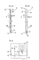
- a modeling rod 3 is in Fig. 3 shown. It is of elongated, straight shape and has a substantially square cross-section. The length is, for example, 30 cm, with a cross-sectional area of, for example, 3 ⁇ 3 mm.
- the modeling 3 is fixed and essentially rigid, yet so flexible that it does not break in conventional handling. It is constructed of a single-component meltable plastic material, produced by means of an injection molding process and has a surface profile changing in rod longitudinal direction 9. This profile is formed by arranged on two opposite side surfaces 11, 12 of the rod 3 connecting elements in the form of substantially perpendicular from the side surfaces 11, 12 protruding teeth 13.
- the arranged on the one side surface 11 first row of teeth is to that on the other, opposite Side surface 12 arranged second row of teeth arranged offset such that the material volume of the rod 3 seen in the rod longitudinal direction 9 does not change.
- the rod 3 has connecting elements 15, 16. These are exemplified here as tongue and groove elements. Groove 15 and spring 16 protrude from complementary connecting surfaces 17, which result from the fact that the ends 14 of the modeling 3 are chamfered. In the linked state of the rods 3, the connecting surfaces 17 of adjacent rods abut each other.
- the required modeling rods 3 are fed to the extrusion head 6 in succession.
- the 3D printer 1 an electric motor drive 5, which causes the advance of the modeling material.
- the drive 5 comprises two opposing gears 18. The teeth of these gears 18 are designed such that they serve as acting on the modeling 3 and with the profile elements 13 of the modeling 3 positively cooperating feed elements.
- 3D printers 1 having a plurality of extrusion heads 6 operating in parallel or in succession, in which two or more modeling rods 3 are provided simultaneously.
- one of the modeling rods 3 serves to provide support material for the construction of support structures, which can easily be removed again after the object 2 has cured.
- a certain number of predefined modeling rods 3 are required.
- the length of the modeling rods 3 is of the to be manufactured object 2, as well as their order of use is specified.
- the basis for the production of the modeling rods 3 is a data model of the object 2, which is present for example in STL format.
- the required modeling rods 3 are preferably automatically fed to the extrusion head 6 after they are automatically connected together.
- the 30-printer 1 has a material supply device 19 fixedly connected to or optionally connectable to the extrusion head 6, as in FIG Fig. 4 shown.
- the supply device 19 comprises a storage container 21 for receiving a number of modeling rods 3, preferably in a defined or definable order.
- a connector 22 which receives the rods 3 from the reservoir 21 and connects at their ends 14 together.
- the rods 3 are preferably supplied to the connector 22 automatically, for example by the action of gravity, or with the aid of a motor drive.
- the connector 22 interconnects the rods 3 by making a connection of the connecting element provided at the end 14 of the one modeling rod 3 with the connecting element provided at the end 14 of the next modeling rod 3. If the connecting elements are, for example, latching elements, the connector 22 establishes the latching connection by latching the latching elements. In Fig. 4 the connection is symbolized by a point 23.
- the connector 22 thus produces linked rods in the form of a rod assembly 24, which by means known to those skilled in the means, for example a further drive, the Extrusion head 6 are supplied and there ensure a continuous flow of material.
- modeling rod packages are provided in which the rods 3 required for the production of a specific object 2 are already contained in the correct arrangement.
- profiling described in connection with the modeling rods 3 according to the invention in conventional modeling filament 103, which is in roll form. Also in this case, a more precise supply of material is achieved. If the modeling filament 103 has a circular cross-section, profiling can be achieved in a particularly simple manner, as in the case of modeling rods 3 having a circular cross-section, by introducing notches into the filament body as profile elements which, with corresponding teeth of the filament drive, form a positive drive and thus ensure a particularly uniform material supply.
Landscapes
- Chemical & Material Sciences (AREA)
- Engineering & Computer Science (AREA)
- Materials Engineering (AREA)
- Manufacturing & Machinery (AREA)
- Physics & Mathematics (AREA)
- Mechanical Engineering (AREA)
- Optics & Photonics (AREA)
Applications Claiming Priority (1)
| Application Number | Priority Date | Filing Date | Title |
|---|---|---|---|
| DE102012002419 | 2012-02-09 |
Publications (1)
| Publication Number | Publication Date |
|---|---|
| EP2626192A1 true EP2626192A1 (fr) | 2013-08-14 |
Family
ID=47552871
Family Applications (1)
| Application Number | Title | Priority Date | Filing Date |
|---|---|---|---|
| EP13000009.4A Withdrawn EP2626192A1 (fr) | 2012-02-09 | 2013-01-02 | Matériau de modelage et procédé et dispositif de fabrication d'un objet tridimensionnel par dépôt en fusion |
Country Status (3)
| Country | Link |
|---|---|
| US (1) | US20130209739A1 (fr) |
| EP (1) | EP2626192A1 (fr) |
| DE (1) | DE102013000015A1 (fr) |
Families Citing this family (13)
| Publication number | Priority date | Publication date | Assignee | Title |
|---|---|---|---|---|
| WO2013138204A1 (fr) | 2012-03-13 | 2013-09-19 | Mikulak James | Matériaux pour procédés de fabrication d'additif à base de poudre |
| WO2015048155A1 (fr) * | 2013-09-24 | 2015-04-02 | Fenner U.S., Inc. | Filament amélioré pour une modélisation par dépôt en fusion |
| US9919340B2 (en) | 2014-02-21 | 2018-03-20 | Regal Beloit America, Inc. | Method for making a component for use in an electric machine |
| DE102015013216B4 (de) * | 2015-10-09 | 2019-03-28 | Moritz Kölbel | Verfahren und Vorrichtung zur Herstellung von Filament zur Zuführung zu einem FDM-Drucker |
| CN113087930A (zh) | 2015-12-22 | 2021-07-09 | 赢创运营有限公司 | 用于生产可消耗性粉末的系统和方法 |
| JP6961972B2 (ja) * | 2017-03-24 | 2021-11-05 | 富士フイルムビジネスイノベーション株式会社 | 立体形状成形装置、情報処理装置及びプログラム |
| WO2018200306A1 (fr) * | 2017-04-24 | 2018-11-01 | Desktop Metal, Inc. | Dispositif d'alimentation en tiges à des fins d'impression tridimensionnelle (3d) |
| US10807310B2 (en) * | 2017-07-27 | 2020-10-20 | Robert Bosch Tool Corporation | 3D printer nozzle gap setting by force feedback |
| US10449717B2 (en) * | 2017-11-30 | 2019-10-22 | Bulent Besim | Integrated cooling system for cooling filament of an additive manufacturing machine |
| US10449719B2 (en) * | 2017-12-01 | 2019-10-22 | Bulent Besim | System for feeding filament to a nozzle in an additive manufacturing machine |
| US11440252B2 (en) | 2018-07-26 | 2022-09-13 | Essentium, Inc. | High speed extrusion 3D printer nozzle |
| US11065811B2 (en) | 2019-03-20 | 2021-07-20 | Essentium, Inc. | Three-dimensional printer head including an automatic touchdown apparatus |
| DE102019002203B3 (de) * | 2019-03-22 | 2020-07-16 | ThixoAM GmbH | Verfahren und Vorrichtung für die additive Fertigung von Erzeugnissen aus Metalllegierungen |
Citations (7)
| Publication number | Priority date | Publication date | Assignee | Title |
|---|---|---|---|---|
| EP0426363A2 (fr) * | 1989-10-30 | 1991-05-08 | Stratasys Inc. | Dispositif et méthode pour créer des objets en trois dimensions |
| WO1997019798A2 (fr) * | 1995-11-13 | 1997-06-05 | Stratasys, Inc. | Procede et appareil de realisation de prototypes solides |
| WO1999060508A1 (fr) * | 1998-05-20 | 1999-11-25 | Stratasys, Inc. | Support de prototypage rapide hydrosoluble et materiau pour moule |
| CN2438567Y (zh) * | 2000-08-25 | 2001-07-11 | 吕正庆 | 三角形塑料焊条 |
| US20030044593A1 (en) * | 2001-01-02 | 2003-03-06 | Vaidyanathan K. Ranji | Continuous fiber reinforced composites and methods, apparatuses, and compositions for making the same |
| KR20040052842A (ko) * | 2004-04-13 | 2004-06-23 | 한동흔 | 용접봉 |
| US20110076495A1 (en) * | 2009-09-30 | 2011-03-31 | Stratasys, Inc. | Consumable materials having topographical surface patterns for use in extrusion-based digital manufacturing systems |
-
2013
- 2013-01-02 EP EP13000009.4A patent/EP2626192A1/fr not_active Withdrawn
- 2013-01-02 DE DE102013000015A patent/DE102013000015A1/de not_active Withdrawn
- 2013-02-08 US US13/762,893 patent/US20130209739A1/en not_active Abandoned
Patent Citations (7)
| Publication number | Priority date | Publication date | Assignee | Title |
|---|---|---|---|---|
| EP0426363A2 (fr) * | 1989-10-30 | 1991-05-08 | Stratasys Inc. | Dispositif et méthode pour créer des objets en trois dimensions |
| WO1997019798A2 (fr) * | 1995-11-13 | 1997-06-05 | Stratasys, Inc. | Procede et appareil de realisation de prototypes solides |
| WO1999060508A1 (fr) * | 1998-05-20 | 1999-11-25 | Stratasys, Inc. | Support de prototypage rapide hydrosoluble et materiau pour moule |
| CN2438567Y (zh) * | 2000-08-25 | 2001-07-11 | 吕正庆 | 三角形塑料焊条 |
| US20030044593A1 (en) * | 2001-01-02 | 2003-03-06 | Vaidyanathan K. Ranji | Continuous fiber reinforced composites and methods, apparatuses, and compositions for making the same |
| KR20040052842A (ko) * | 2004-04-13 | 2004-06-23 | 한동흔 | 용접봉 |
| US20110076495A1 (en) * | 2009-09-30 | 2011-03-31 | Stratasys, Inc. | Consumable materials having topographical surface patterns for use in extrusion-based digital manufacturing systems |
Also Published As
| Publication number | Publication date |
|---|---|
| DE102013000015A1 (de) | 2013-08-14 |
| US20130209739A1 (en) | 2013-08-15 |
Similar Documents
| Publication | Publication Date | Title |
|---|---|---|
| EP2626192A1 (fr) | Matériau de modelage et procédé et dispositif de fabrication d'un objet tridimensionnel par dépôt en fusion | |
| DE69215878T2 (de) | Verfahren und vorrichtung zur herstellung von coextrudierten produkten | |
| DE102019106873B4 (de) | Extruder | |
| DE2338186A1 (de) | Verfahren und vorrichtung zum umspritzen eines langgestreckten kerns mit einem mantel aus thermoplastischem werkstoff, dessen aussendurchmesser laengs des kerns periodisch schwankt | |
| DE102015122647A1 (de) | Vorrichtung und Verfahren zur Herstellung eines dreidimensionalen Gegenstandes mit einer Faserzuführeinrichtung | |
| DE1273800B (de) | Verfahren und Vorrichtung zum Herstellen eines Schlauches aus thermoplastischem Kunststoff mit einer in der Schlauchwand eingebetteten Wendel | |
| DE3505972A1 (de) | Verfahren und vorrichtung zur herstellung von borstenwaren | |
| DE102016117544B4 (de) | Vorrichtung zur Herstellung von Dichtungsringen, Steuerungseinrichtung und deren Verwendung in dieser Vorrichtung, Verwendung wenigstens einer drehbar gelagerten Scheibe in dieser Vorrichtung, und Verfahren zur Herstellung von Dichtungsringen | |
| EP4010165A1 (fr) | Procédé et appareil d'extrusion destinés à l'extrusion de matière plastique renforcée par des fibres pour la fabrication additive d'un élément | |
| CH433702A (de) | Verfahren und Vorrichtung zur Herstellung von verstärkten Kunstharzgegenständen aus faserverstärktem Kunstharzmaterial | |
| EP3180183A1 (fr) | Procédé et dispositif de fabrication d'un profilé en matière plastique | |
| EP3424690A1 (fr) | Procédé et dispositif de fabrication d'une grille d'armature | |
| EP2773499B1 (fr) | Procédé pour réaliser un objet en matière plastique renforcé | |
| EP1928279B1 (fr) | Brosse cylindrique, et son procédé de production | |
| EP1126764B1 (fr) | Procede pour produire un element de fermeture auto-agrippante | |
| AT520657B1 (de) | Druckkopf für das schichtweise Aufbringen von Material | |
| DE1962926C3 (de) | Verfahren zur Herstellung einer Bürste | |
| DE102007024380B4 (de) | Verfahren zum Herstellen eines Formsteins und Formsteinfüllvorrichtung | |
| DE102016114900B4 (de) | Verfahren zur Herstellung von Pinseln sowie Pinsel | |
| DE29623179U1 (de) | Heißschneidvorrichtung | |
| DE2829566A1 (de) | Vorrat oder magazin von fortlaufend miteinander verbundenen befestigungselementen | |
| DE2205077A1 (de) | Verfahren und Vorrichtung zum Herstellen von Wabenstrukturen | |
| DE1817182C3 (de) | Verfahren zum Herstellen einer textUähnlichen bahnförmigen Lamellen-Struktur | |
| DE3742416A1 (de) | Verfahren und vorrichtung zum herstellen eines profilstabes aus thermoplastischem kunststoff | |
| EP4112274A1 (fr) | Structure de tête d'impression pour la fabrication additive au moyen de fibres sans fin et matériaux matriciels thermoplastiques permettant de couper dans la zone chaude de la tête d'impression au moyen d'un mouvement axial ou rotatif |
Legal Events
| Date | Code | Title | Description |
|---|---|---|---|
| PUAI | Public reference made under article 153(3) epc to a published international application that has entered the european phase |
Free format text: ORIGINAL CODE: 0009012 |
|
| AK | Designated contracting states |
Kind code of ref document: A1 Designated state(s): AL AT BE BG CH CY CZ DE DK EE ES FI FR GB GR HR HU IE IS IT LI LT LU LV MC MK MT NL NO PL PT RO RS SE SI SK SM TR |
|
| AX | Request for extension of the european patent |
Extension state: BA ME |
|
| 17P | Request for examination filed |
Effective date: 20140131 |
|
| RBV | Designated contracting states (corrected) |
Designated state(s): AL AT BE BG CH CY CZ DE DK EE ES FI FR GB GR HR HU IE IS IT LI LT LU LV MC MK MT NL NO PL PT RO RS SE SI SK SM TR |
|
| RAP1 | Party data changed (applicant data changed or rights of an application transferred) |
Owner name: FIT AG |
|
| 17Q | First examination report despatched |
Effective date: 20150630 |
|
| STAA | Information on the status of an ep patent application or granted ep patent |
Free format text: STATUS: THE APPLICATION IS DEEMED TO BE WITHDRAWN |
|
| 18D | Application deemed to be withdrawn |
Effective date: 20160112 |