EP2626466A2 - Dispositif et procédé destinés à la fixation ultérieure d'un rail dans une pose sans ballast - Google Patents
Dispositif et procédé destinés à la fixation ultérieure d'un rail dans une pose sans ballast Download PDFInfo
- Publication number
- EP2626466A2 EP2626466A2 EP13000539.0A EP13000539A EP2626466A2 EP 2626466 A2 EP2626466 A2 EP 2626466A2 EP 13000539 A EP13000539 A EP 13000539A EP 2626466 A2 EP2626466 A2 EP 2626466A2
- Authority
- EP
- European Patent Office
- Prior art keywords
- substrate
- rail
- receiving channel
- base plate
- grout
- Prior art date
- Legal status (The legal status is an assumption and is not a legal conclusion. Google has not performed a legal analysis and makes no representation as to the accuracy of the status listed.)
- Withdrawn
Links
- 238000000034 method Methods 0.000 title claims description 72
- 239000000758 substrate Substances 0.000 claims abstract description 78
- 230000005540 biological transmission Effects 0.000 claims abstract description 50
- 238000002347 injection Methods 0.000 claims abstract description 18
- 239000007924 injection Substances 0.000 claims abstract description 18
- 239000011440 grout Substances 0.000 claims description 52
- 239000007787 solid Substances 0.000 claims description 17
- 238000004873 anchoring Methods 0.000 claims description 9
- 238000009434 installation Methods 0.000 claims description 9
- 238000007596 consolidation process Methods 0.000 claims description 7
- 239000002131 composite material Substances 0.000 claims description 6
- 230000003014 reinforcing effect Effects 0.000 claims description 6
- 238000001514 detection method Methods 0.000 claims description 3
- 238000001839 endoscopy Methods 0.000 claims description 2
- 230000035515 penetration Effects 0.000 claims description 2
- 239000010410 layer Substances 0.000 description 19
- 230000002950 deficient Effects 0.000 description 10
- 239000000853 adhesive Substances 0.000 description 6
- 230000001070 adhesive effect Effects 0.000 description 6
- 239000012790 adhesive layer Substances 0.000 description 6
- 238000004026 adhesive bonding Methods 0.000 description 4
- 239000010426 asphalt Substances 0.000 description 3
- 239000004033 plastic Substances 0.000 description 3
- 229920003023 plastic Polymers 0.000 description 3
- 238000007711 solidification Methods 0.000 description 3
- GNFTZDOKVXKIBK-UHFFFAOYSA-N 3-(2-methoxyethoxy)benzohydrazide Chemical compound COCCOC1=CC=CC(C(=O)NN)=C1 GNFTZDOKVXKIBK-UHFFFAOYSA-N 0.000 description 2
- FGUUSXIOTUKUDN-IBGZPJMESA-N C1(=CC=CC=C1)N1C2=C(NC([C@H](C1)NC=1OC(=NN=1)C1=CC=CC=C1)=O)C=CC=C2 Chemical compound C1(=CC=CC=C1)N1C2=C(NC([C@H](C1)NC=1OC(=NN=1)C1=CC=CC=C1)=O)C=CC=C2 FGUUSXIOTUKUDN-IBGZPJMESA-N 0.000 description 2
- 229910000831 Steel Inorganic materials 0.000 description 2
- 230000015572 biosynthetic process Effects 0.000 description 2
- 150000001875 compounds Chemical class 0.000 description 2
- 239000004567 concrete Substances 0.000 description 2
- 238000011161 development Methods 0.000 description 2
- 230000018109 developmental process Effects 0.000 description 2
- 238000005553 drilling Methods 0.000 description 2
- 230000000694 effects Effects 0.000 description 2
- 238000003780 insertion Methods 0.000 description 2
- 230000037431 insertion Effects 0.000 description 2
- 230000007774 longterm Effects 0.000 description 2
- 238000005067 remediation Methods 0.000 description 2
- 239000010959 steel Substances 0.000 description 2
- 238000013461 design Methods 0.000 description 1
- 238000006073 displacement reaction Methods 0.000 description 1
- 238000009826 distribution Methods 0.000 description 1
- 230000009977 dual effect Effects 0.000 description 1
- 229920001971 elastomer Polymers 0.000 description 1
- 239000000945 filler Substances 0.000 description 1
- 230000012447 hatching Effects 0.000 description 1
- 239000004413 injection moulding compound Substances 0.000 description 1
- 238000002955 isolation Methods 0.000 description 1
- 239000007788 liquid Substances 0.000 description 1
- 238000004519 manufacturing process Methods 0.000 description 1
- 239000000463 material Substances 0.000 description 1
- 238000012544 monitoring process Methods 0.000 description 1
- 239000002245 particle Substances 0.000 description 1
- 230000002093 peripheral effect Effects 0.000 description 1
- 239000004814 polyurethane Substances 0.000 description 1
- 229920005749 polyurethane resin Polymers 0.000 description 1
- 238000004382 potting Methods 0.000 description 1
- 229920005989 resin Polymers 0.000 description 1
- 239000011347 resin Substances 0.000 description 1
- 239000000243 solution Substances 0.000 description 1
- 238000004078 waterproofing Methods 0.000 description 1
Images

Classifications
-
- E—FIXED CONSTRUCTIONS
- E01—CONSTRUCTION OF ROADS, RAILWAYS, OR BRIDGES
- E01B—PERMANENT WAY; PERMANENT-WAY TOOLS; MACHINES FOR MAKING RAILWAYS OF ALL KINDS
- E01B31/00—Working rails, sleepers, baseplates, or the like, in or on the line; Machines, tools, or auxiliary devices specially designed therefor
-
- E—FIXED CONSTRUCTIONS
- E01—CONSTRUCTION OF ROADS, RAILWAYS, OR BRIDGES
- E01B—PERMANENT WAY; PERMANENT-WAY TOOLS; MACHINES FOR MAKING RAILWAYS OF ALL KINDS
- E01B21/00—Track superstructure adapted for tramways in paved streets
- E01B21/04—Special fastenings, joint constructions, or tie-rods
-
- E—FIXED CONSTRUCTIONS
- E01—CONSTRUCTION OF ROADS, RAILWAYS, OR BRIDGES
- E01B—PERMANENT WAY; PERMANENT-WAY TOOLS; MACHINES FOR MAKING RAILWAYS OF ALL KINDS
- E01B31/00—Working rails, sleepers, baseplates, or the like, in or on the line; Machines, tools, or auxiliary devices specially designed therefor
- E01B31/20—Working or treating non-metal sleepers in or on the line, e.g. marking, creosoting
Definitions
- the invention relates to a device for post consolidation of a loosened rail, in particular a tram rail in a ballastless laying and an associated method.
- ballastless superstructure It is known from the prior art, in particular tram rails in a ballastless installation, also referred to as ballastless superstructure, to order, so as to obtain a superstructure, which is on the one hand more resilient than ballast superstructures and which on the other hand without problems by other, not rail-bound Vehicles and persons are navigable or accessible.
- the rails are fixed on a solid surface, such as concrete or bitumen, and connected via so-called Kammer Strukturllsteine to adjacent surfaces, such as paving stones or asphalt, and connected both acoustically, as well as electrically isolated.
- the upper end of the rails is achieved by the introduction of a potting compound, also referred to as Schienenl Kunststoffsverguss, between the rail and the adjacent surfaces.
- additional rubber profiles may be provided to improve the isolation of the rails between the chamber fillers and adjacent surfaces.
- the attachment of the rails on the solid surface is usually by gluing them, for example by means of a 2-component plastic adhesive.
- the plastic adhesive used preferably acts vibration-reducing to attenuate the, caused by driving on the rails, vibration and thus to protect the solid base and reduce sound transmission.
- the listed repair method is disadvantageous in that a considerable effort to expose and repair the defective track section is necessary and that this results in a long downtime of the rail section and on the other hand correspondingly high costs for repair and temporary non-use of the corresponding rail sections.
- the method does not provide long-term effective post consolidation of the rail section, since the rail is connected after repair only in the same way with the ground and thus it can come by thermal and fürfahrbelastept to a new shaking loose the rail section.
- An inventive device for post consolidation of a rail in a ballastless laying has a base plate, a receiving channel, an anchor element, a grout, a transmission element, a clamping element and a spring element.
- the base plate according to the invention is at least partially glued to a substrate next to the rail, wherein the height of the base plate preferably corresponds to the minimum height of a supplementflansches the rail.
- Underground of the rail is understood in this context, the entire section of a track superstructure, which is located below the foot flange of the rail.
- the substrate comprises a substructure located directly under the rail, for example made of concrete or bitumen, and a filling arranged laterally along the, below the Schienenfußflansches, adhesive layer arranged filling, for example, as AFB filling.
- the partial bonding of the base plate to the substrate is preferably carried out in the region of, adjacent to the adhesive layer, filling.
- the base plate has a recess, preferably as a borehole, wherein the recess extends over the entire thickness of the base plate.
- the inventively provided receiving channel is particularly advantageously designed so that it passes through both the recess of the base plate, as well as a loosened portion of the substrate and is introduced into a fixed portion of the substrate.
- the receiving channel is thus thus extended by the recess of the base plate.
- the loosened section of the substructure denotes the areas in which the substructure has detached due to the loads occurring.
- fixed sections of the subsurface are understood to mean the deeper areas, which are not damaged by a loosening of the rail.
- the receiving channel in the region of the substrate preferably by means of piercing the loosened portions of the substrate, introduced into a predetermined depth in the solid portion of the substrate.
- the receiving channel is used in the present invention for receiving the anchor element, which according to the invention after insertion of the receiving channel is inserted into this in such a way that the anchor element passes through both the base plate in the region of the recess, as well as the loosened portions of the substrate and in particular to the end of the Receiving channel is driven into the solid ground.
- the diameter of the anchor element is particularly advantageously designed so that an annular space is formed between the anchor element and the receiving channel.
- the Verpressmasse invention is introduced, wherein the Verpressmasse in their consistency is formed so that on the one hand, the annulus between anchoring element and receiving channel and the other, approximately in the loosened portion of the substrate and in the area between the loose ground and the solid ground forming cavities, can be filled by the Verpressmasse.
- PU resin polyurethane resin
- the introduction of the grout is preferably carried out with the aid of a known injection packer, which is inserted into the annular space between the receiving channel and anchoring element and removed immediately after the introduction of the grout from the annulus again.
- the injection packer is taken as a particular advantage of the recess of the base plate and fixed in this so that a uniform introduction of the grout is ensured in the annulus and in the cavities.
- Such injection packers are known to be used, for example, in structural waterproofing or crack remediation.
- this hardens particularly advantageous both in the annulus between anchor element and receiving channel and in the cavities, in particular, the curing of the grout in the annulus advantageously leads to the anchor element is set in its position within the receiving channel ,
- a device further comprises a transmission element, which is arranged above the base flange of the rail and above the base plate and which rests on both the foot flange of the rail, as well as on the base plate.
- the transmission element is particularly advantageous also penetrated by the anchor element.
- the transmission element may for example also be present as a plate or else in the form of a yoke or as a U-shaped element.
- the transmission element has an opening which according to the invention corresponds with the recess of the base plate and thus with the receiving channel and which is also penetrated by the anchor element.
- the transmission element according to the invention both point or linear or even flat on the foot flange of the rail and rest on the base plate.
- clamping element and the spring element according to the invention are arranged on the anchor element, that the clamping element above the transmission element at an upper end of the anchor element and the spring element between the clamping element and the transmission element and thus the spring element by an axial change in position of the clamping element, in Direction of the transmission element, can be braced.
- the clamping forces arising during the tensioning of the spring element are transmitted in a particularly advantageous manner both to the foot flange of the rail and to the base plate. It is thereby one, at least partially, elastic location of the rail on the solid surface causes, with a special advantage of the foot flange of the rail not must be pierced.
- the rail is permanently biased in the axial direction of the anchor element against the ground. Vertical movements of the rail during load changes, as a result of overrunning, are suppressed, thereby counteracting further loosening.
- the imprint makes it difficult to tear off the substrate or to rip it in the ground.
- the rail remains associated with a limited mobility, which allows the rail in particular advantageous to perform thermal expansion processes, without causing a renewed loosening of the rail in the ballastless installation.
- the base plate comes as a particular advantage of the invention to a dual function.
- the base plate serves on one side to support the transmission element and the applied biasing forces, on the other hand, a secure receiving the injection packer during the introduction of the grout is ensured by the base plate.
- the base plate acts as an adhesive packer in conjunction with the injection packer. The otherwise necessary with undefined surfaces attachment of a Klebepackers deleted.
- the material acting on the foot flange of the rail bias can be particularly advantageous adapted to the loads occurring.
- a device according to the invention offers the particular advantage that the remediation of a defective Track section without Substanzeeingriffe in the rail, in particular of the foot flange of the rail takes place. This is particularly advantageous if, for example, the rail or its foot flange is not released by the rail manufacturer for a direct piercing.
- the base plate is arranged in a defined horizontal distance from the foot flange of the rail on the ground, or glued.
- the rail in particular in curved sections, to execute relative movements to the base plate in the region of the device. It is thus ensured that there is no collision between rail and base plate, for example during thermal expansion processes of the rail.
- the anchor element are designed as threaded bolts and the clamping element as a nut.
- the clamping means screwed onto the anchor member and by screwing the clamping means a defined tension of the spring element can be achieved.
- settlement processes of the rail in the superstructure can be compensated.
- a further advantageous embodiment of the invention provides that the spring element is designed as a plate spring.
- the use of a plate spring is particularly useful when only a small space between the foot flange of the rail and the rest of the superstructure, especially between foot flange and about used Kammerhellsteinen, is available and only a small amount of travel is needed.
- the spring element is designed as a helical spring. Since coil springs are manufactured inexpensively, by their use, the manufacturing cost of a device according to the invention can be kept low.
- the receiving channel reinforcing elements are arranged, which are preferably completely, but at least partially enclosed by the Verpressmasse.
- the reinforcing elements consist for example of steel, wherein the steel is preferably present as a wire mesh or in the form of individual, wire-shaped elements.
- a preferred development of the device according to the invention further provides that the receiving channel introduced into the substrate has a diameter which corresponds at least to twice the diameter of the anchor element.
- the base plate is carried out on the ground in such a way that the receiving channel, even with an enlarged diameter, at least partially covered by the base plate.
- the coverage of the receiving channel through the base plate is preferably so large that no Verpressmasse can escape from the receiving channel in the direction of the Schienenfußflansches.
- the receiving channel also passes through the fixed portion of the substrate and leads to a, located below the fixed portion of the substrate, supporting layer.
- the base layer in this context consists for example of an aggregate and in particular has a porous structure.
- the grout can also be introduced into the porous support layer and harden in this.
- existing voids are filled in by the Verpressmasse and formed a composite of grout and aggregate in this.
- the composite of grout and aggregate acts as a particular advantage as an abutment for the anchor element, whereby the strength of the device according to the invention is further improved.
- the grout in the base layer below the rail surface, for example, with the aid of injection hoses, which are preferably disposed within the receiving channel and extend into the support layer.
- the grout is introduced via the injection hoses only in the support layer when the grout in the receiving channel already, at least partially cured.
- a kind of pressure chamber is formed in the direction of the receiving channel, which particularly advantageously prevents escape of the Verpressmasse from the support layer in the receiving channel.
- the one apparatus for post consolidation of a rail in a ballastless installation according to claim 9 comprises a plurality of devices according to claim 1.
- the inventive arrangement of several devices according to claim 1 is used when not only very short sections should be consolidated.
- At least one device according to claim 1 is arranged in the foot flange of the rail to the right and left of the rail web.
- the arrangement of the plurality of devices according to claim 1 along the longitudinal direction of the rail takes place in an equally advantageous embodiment of the invention at a defined distance and mutually offset on both sides of the rail web.
- post-solidification In order to re-solidify a loosened rail, in particular a tram rail, hereinafter referred to as post-solidification, according to the invention a post-solidification method is provided, which comprises the following method steps.
- a base plate in the region of a foot flange of the rail is glued to a substrate of the rail.
- the gluing of the base plate is carried out particularly advantageous such that the height of the top of the base plate after adhering to the substrate corresponds to the height of the researchingflansches the rail in the area adjacent to the base plate area. It is not absolutely necessary that the base plate is in a horizontal position after it has been stuck to the substrate. Rather, the base plate can be depending on the application after gluing in a defined angle.
- a base plate to be bonded has, according to the invention, a recess through which a receiving channel is set in a second method step b).
- the receiving channel is thereby introduced, for example by drilling, in the laying of the rail, that this both the recess of the base plate, as well as one, located under the foot flange of the rail, loosened Interspersed section of the substrate and penetrates into a solid section of the substrate.
- an anchor element is used in a further method step c), which penetrates particularly advantageously both the recess of the base plate, and the loosened portion of the substrate and is introduced into the fixed portion of the substrate.
- the anchor element is designed such that its diameter is smaller than that of the receiving channel. In this way, it is inventively to form an annular space between the anchor element and the receiving channel.
- a fourth method step d) now provides that a hardenable grout is introduced into the annular space between the anchoring element and the receiving channel.
- the introduction of the grout is preferably carried out under pressure, wherein the grout is particularly advantageous allows both fill the annulus between armature element and receiving channel, as well as penetrate into cavities in or between the loose and the solid portion of the substrate and this also largely completely fill.
- so-called high-pressure packer which are designed in this case so that they can penetrate into the annulus and bring the grout into the annulus.
- such a high pressure packer is particularly advantageously absorbed by the recess of the base plate and so in this fixes that a uniform introduction of the grout is guaranteed.
- the high-pressure packer is again removed from the receiving channel, respectively from the annulus between anchor element and receiving channel.
- a subsequent process step e the curing time of the grout is awaited.
- a transmission element is arranged above the base plate and above the base flange of the rail so that it is also penetrated by the anchoring element.
- the transmission element has an opening which is capable of receiving the anchor element.
- the arrangement of the transmission element takes place within the device according to the invention in a particularly advantageous manner such that the transmission element rests on both the base plate, as well as on the foot flange of the rail.
- a spring element is arranged in the region of the exposed end of the anchor element.
- the spring element to be arranged according to the invention depending on the available space, be designed both as a plate and as a coil spring.
- all other types of springs come into question, which meet the requirements.
- a clamping element is arranged on the exposed end of the anchor element, in particular above the spring element.
- the anchor element for example, as a threaded rod and the clamping element formed for example as a nut, wherein the clamping element is screwed according to the invention on the anchor element.
- a last method step i) now provides that the spring element is braced by an axial change of the position of the clamping element in the direction of the transmission element.
- the bracing of the spring element takes place such that the rail remains assigned in a particularly advantageous manner a displaceability, which allows it to perform, in particular thermal expansion processes in the longitudinal direction.
- a detection of the loosened sections of the superstructure takes place before the process step a) in a process step 0) a detection of the loosened sections of the superstructure.
- a detection of loose sections of the superstructure can be done, for example, by determining the movements of the rail.
- a continuous monitoring of the entire rail system in the sense of an early warning system is conceivable, whereby defective sections in the superstructure would be recognized early and could be rehabilitated.
- An equally advantageous variant of the post-solidification process according to the invention provides that between method steps b) and c), in an additional method step b1), an examination of the receiving channel for complete penetration of the loosened portion of the substrate is performed.
- the method step b1) provided according to the invention is carried out in an advantageous embodiment of the method by an endoscopy of the receiving channel.
- Video endoscopes are used in particular, which are inserted into the recording channel after the recording channel has been set and reproduce a corresponding image recording of the inner profile of the recording channel.
- the receiving channel is inventively designed so that its diameter corresponds to at least twice the diameter of the anchor element.
- a base plate is glued to the substrate next to a foot flange of the rail, wherein the base plate is glued to the ground next to the rail, that the previously introduced receiving channel is covered by the base plate. Furthermore, a recess is provided in the base plate according to the invention, which corresponds to the receiving channel in such a way that the anchor element can be introduced through the recess of the base plate into the receiving channel.
- the introduction of the anchor element in the receiving channel takes place in a third method step c) such that the anchor element both the recess of the base plate, as well as the loosened portion of the substrate interspersed and is introduced into the solid portion of the substrate.
- a hardenable grout is introduced into an annular space formed between the anchoring element and the lateral surface of the receiving channel and into cavities in or between the loosened section and the fixed section of the substrate below the rail.
- the introduction of the grout takes place in this context, for example, with the aid of a high pressure packer, which is at least partially introduced into the annulus.
- process step e the curing time of the grout is awaited.
- the anchor element is fixed in the receiving channel on the one hand, and on the other hand, existing cavities are sealed in or between the loose and the solid portion of the substrate.
- a transmission element is arranged above the base plate and above the base flange of the rail so that it is also penetrated by the anchoring element.
- the transmission element has an opening which is capable of receiving the anchor element.
- the arrangement of the transmission element takes place within the device according to the invention in a particularly advantageous manner such that the transmission element rests on both the base plate, as well as on the foot flange of the rail.
- a spring element is arranged in the region of the exposed end of the anchor element.
- the spring element to be arranged according to the invention depending on the available space, be designed both as a plate and as a coil spring.
- all other types of springs come into question, which meet the requirements.
- a clamping element is arranged on the exposed end of the anchor element, in particular above the spring element.
- the anchor element for example, as a threaded rod and the clamping element formed for example as a nut, wherein the clamping element is screwed according to the invention on the anchor element.
- a last method step i) now provides that the spring element is braced by an axial change of the position of the clamping element in the direction of the transmission element.
- the bracing of the spring element takes place such that the rail remains assigned in a particularly advantageous manner a displaceability, which allows it in particular to carry out thermal expansion processes in the longitudinal direction.
- a particularly advantageous embodiment of the method according to claim 15 provides that in the method step a) the receiving channel passes through both a loosened portion of the substrate and a fixed portion of the substrate and leads to a, located under the fixed portion of the substrate, the support layer and that in process step d) the grout is also introduced into sections of the base course below the fixed section of the subsoil.
- process step d) is preceded by a process step c1), wherein in process step c1) at least one injection hose is inserted into the receiving channel in such a way that the injection hose into the Carrier layer penetrates below the fixed portion of the substrate.
- the advantageous embodiment of the method provides that between the process steps e) and f) in an additional process step e1) via the injection hose, the grout is also introduced into the support layer.
- the introduced grout then cures in the base course and a local composite of the particles of the base course and the hardened grout is formed.
- This composite acts in a particularly advantageous manner in the sense of an abutment for the anchor element, which in particular the long-term strength of a, solidified by the Nachverfest Trentshabilit invention, rail is guaranteed.
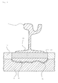
- Fig. 1 shows a schematic representation of a defective track section with a rail 1 in a ballastless laying.
- the rail 1 in particular in the region of a therapeuticflansches 10, via an adhesive layer 13 with a loosened portion 8 of a substrate firmly connected. Adhering to the adhesive layer 13 continues to be bordered on both sides of the base flange 10 of the rail 1 by a filling 12.
- the loosened portion 8 opposite is a fixed portion 9 of the substrate, from which the loose portion 8, for example, by thermal and / or mechanical loads, has solved.
- the loosening of the defective track section is accompanied by the formation of cavities 11 in the area between the loosened section 8 and the fixed section 9 of the substrate.
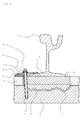
- An inventive device for post consolidation of a rail 1 in a ballastless laying has a, provided with a recess base plate 2 and a receiving channel 3, wherein the base plate 2 in the region of theticianflansches 10 of the rail 1 to the substrate of the rail 1 and in particular to the filling 12 is glued and wherein the receiving channel 3, both the base plate 2 in the region of the recess, as well as the loosened portion 8 of the substrate and the cavities 11 completely penetrated and introduced into the fixed portion 9 of the substrate.
- the introduction of the receiving channel 3 in the ground is preferably carried out by drilling.
- the receiving channel 3 is used according to the invention for receiving an anchor element 4, which particularly advantageously penetrates both the base plate 2, and the loosened portion 8 of the substrate and the cavities 11 and is introduced into the fixed portion 9 of the substrate.
- receiving channel 3 and anchor element 4 are particularly advantageously chosen so that an annular space is formed between them.
- a Verpressmasse (not shown) is introduced into the annular space between anchor member 4 and receiving channel 3 according to the invention.
- the introduction of the grout is particularly advantageous with the aid of an injection packer (not shown), which is introduced into the annulus.
- the recess of the base plate 2 serves to receive and fix the injection packer, so that a uniform introduction of the grout is guaranteed.
- Verpressmasse is inventively chosen so that it penetrates both into the annulus, as well as in the existing cavities 11, this fills and in particular closes liquid-tight. After hardening of the grout, especially in the annulus, the anchoring element 4 is fixed in its position and connected to both the fixed portion 9, and with the relaxed portion 8 of the substrate.
- a transmission element 5 is arranged according to the invention.
- the transmission element 5 is also particularly advantageously penetrated by the anchor element 4 and, moreover, rests both on the base flange 10 of the rail 1 and on the base plate 2.
- a spring element 7 and a clamping element 6 are further arranged.
- the rail 1 by the partially elastic bias, associated with a limited mobility, which allows this particular, thermal expansion processes be carried out without it comes to a renewed loosening of the rail 1.
- the base plate 2 is arranged at a horizontal distance from the base flange 10 of the rail 1. This ensures that the rail 1, even after installation of the device, can perform a relative movement to the base plate 2 and thus, for example, in thermal expansion processes of the rail 1 to no collision between the base flange 10 and the base plate 2 comes.
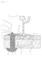
- Fig. 3 shows a device according to the invention with an enlarged receiving channel. 3
- the receiving channel 3 in the present Fig. 3 provided with hatching according to the technical representation of plastics.
- the diameter of the receiving channel 3 is in this case a multiple of the diameter of the anchor element 4th
- abutment 14 is shown.
- the receiving channel 3 passes through the solid portion 9 of the substrate completely and leads to a, located below the fixed portion 9 of the substrate, supporting layer (not shown).
- Verpressmasse is also partially introduced into the support layer and can harden in this.
Landscapes
- Engineering & Computer Science (AREA)
- Architecture (AREA)
- Civil Engineering (AREA)
- Structural Engineering (AREA)
- Mechanical Engineering (AREA)
- Piles And Underground Anchors (AREA)
- Railway Tracks (AREA)
Applications Claiming Priority (1)
| Application Number | Priority Date | Filing Date | Title |
|---|---|---|---|
| DE202012001307U DE202012001307U1 (de) | 2012-02-10 | 2012-02-10 | Vorrichtung zur Nachverfestigung einer Schiene in einer schotterlosen Verlegung |
Publications (2)
| Publication Number | Publication Date |
|---|---|
| EP2626466A2 true EP2626466A2 (fr) | 2013-08-14 |
| EP2626466A3 EP2626466A3 (fr) | 2015-09-16 |
Family
ID=47721946
Family Applications (1)
| Application Number | Title | Priority Date | Filing Date |
|---|---|---|---|
| EP13000539.0A Withdrawn EP2626466A3 (fr) | 2012-02-10 | 2013-02-01 | Dispositif et procédé destinés à la fixation ultérieure d'un rail dans une pose sans ballast |
Country Status (2)
| Country | Link |
|---|---|
| EP (1) | EP2626466A3 (fr) |
| DE (1) | DE202012001307U1 (fr) |
Cited By (1)
| Publication number | Priority date | Publication date | Assignee | Title |
|---|---|---|---|---|
| CN108468257A (zh) * | 2018-04-09 | 2018-08-31 | 浙江鑫湖医疗科技有限公司 | 轨道调整装置及轨道调整方法 |
Family Cites Families (7)
| Publication number | Priority date | Publication date | Assignee | Title |
|---|---|---|---|---|
| GB107517A (en) * | 1916-11-06 | 1917-07-05 | John Gordon | Improved Anchorage for Tramway Rails. |
| DE1257817B (de) * | 1965-11-25 | 1968-01-04 | Meier Hermann Dr Ing | Schienenbefestigung auf Betonschwellen od. dgl. |
| DE4428706A1 (de) * | 1994-08-12 | 1996-02-15 | Heilit & Woerner Bau Ag | Gleisrost auf durchgehender Tragplatte und Verfahren zur Verlegung eines Gleisrostes auf durchgehender Tragplatte |
| DE29702708U1 (de) * | 1997-02-17 | 1997-05-15 | Fried. Krupp Ag Hoesch-Krupp, 45143 Essen Und 44145 Dortmund | Federnde Schienenbefestigung |
| EP1121491B1 (fr) * | 1998-10-16 | 2004-05-26 | Phoenix Aktiengesellschaft | Systeme de rail a isolation electrique |
| DE10248037B3 (de) * | 2002-10-15 | 2004-05-06 | Walter - Heilit Verkehrswegebau Gmbh | Verfahren zur Nachbehandlung einer Schienenfahrbahn |
| EP2405080A1 (fr) * | 2010-07-09 | 2012-01-11 | Sersa Group AG (Schweiz) | Comblement des lézardes dans une traverse de chemin de fer |
-
2012
- 2012-02-10 DE DE202012001307U patent/DE202012001307U1/de not_active Expired - Lifetime
-
2013
- 2013-02-01 EP EP13000539.0A patent/EP2626466A3/fr not_active Withdrawn
Non-Patent Citations (1)
| Title |
|---|
| None |
Cited By (1)
| Publication number | Priority date | Publication date | Assignee | Title |
|---|---|---|---|---|
| CN108468257A (zh) * | 2018-04-09 | 2018-08-31 | 浙江鑫湖医疗科技有限公司 | 轨道调整装置及轨道调整方法 |
Also Published As
| Publication number | Publication date |
|---|---|
| DE202012001307U1 (de) | 2013-05-13 |
| EP2626466A3 (fr) | 2015-09-16 |
Similar Documents
| Publication | Publication Date | Title |
|---|---|---|
| EP2483477B1 (fr) | Dispositif de pontage d'un joint de dilatation | |
| EP1730352B1 (fr) | Procede pour corriger la hauteur d'une voie ferree fixe | |
| EP3437954B1 (fr) | Dispositif de protection | |
| DE10237968B3 (de) | Verfahren zum Anbringen von Zuggliedern an Tragwerken sowie Vorrichtung zur Durchführung des Verfahrens | |
| EP2817465A1 (fr) | Dispositif pour l'application d'une force dans un élément de traction formé de lamelles de bande plate en matière plastique renforcée par des fibres | |
| EP2626466A2 (fr) | Dispositif et procédé destinés à la fixation ultérieure d'un rail dans une pose sans ballast | |
| EP1753916A1 (fr) | Dispositif d'ancrage, barre d'ancrage et procede de fabrication d'un dispositif d'ancrage | |
| EP2626467B1 (fr) | Dispositif et procédé destinés à la fixation ultérieure d'un rail dans une pose sans ballast | |
| EP2893139A1 (fr) | Ensemble d'ancrage haute résistance d'un élément de précontrainte dans une pièce, l'élément de précontrainte comportant une tige de précontrainte, et procédé de production dudit ancrage | |
| EP3301225B1 (fr) | Système de protection de véhicule avec vis pour béton et utilisation dudit vis pour béton | |
| EP3556938B1 (fr) | Rail pour être monté élastiquement | |
| EP2447421B1 (fr) | Connection de chaussée à une surface | |
| DE102013015714B3 (de) | Brückenkappe mit Verankerung und Verfahren zum Anbringen einer Vorrichtung zum Verankern von Brückenkappen | |
| DE19514005A1 (de) | Anordnung und ein Verfahren zum Befestigen einer Betonschwelle auf einer Beton- oder Asphalt-Tragplatte | |
| AT505252B1 (de) | Verfahren zur herstellung eines fahrbahnaufbaues | |
| DE102009044841B4 (de) | Schienenfuge | |
| AT413553B (de) | Gleis für schienenfahrzeuge sowie verfahren zum herstellen eines gleises | |
| DE102011009264B4 (de) | Verfahren und Anordnung eines vorgefertigten Bauelements zur Sanierung von Betonflächen | |
| DE102023114909A1 (de) | Mehrschichtiger Artikel zur Erzeugung einer Haftung zu einer Oberfläche und Verfahren zum Erzeugen einer Haftung zwischen einem mehrschichtigen Artikel und einer Oberfläche | |
| DE102024119728A1 (de) | Verfahren zur Sanierung und Stabilisierung eines Gleisbetts | |
| EP0794288B1 (fr) | Fixation d'une traverse d'acier en Y sur voie rigide | |
| DE102021115681A1 (de) | Verfahren zur Sanierung von Bahnschwellen für Schienenfahrzeuge | |
| DE202010012036U1 (de) | Injektionshilfsvorrichtung zur Fundamentsanierung | |
| DE2612617A1 (de) | Schotterloser eisenbahnoberbau | |
| DE102009043313A1 (de) | Verfahren zur Verankerung eines Maschinenteils in einem Fundament |
Legal Events
| Date | Code | Title | Description |
|---|---|---|---|
| PUAI | Public reference made under article 153(3) epc to a published international application that has entered the european phase |
Free format text: ORIGINAL CODE: 0009012 |
|
| 17P | Request for examination filed |
Effective date: 20130201 |
|
| AK | Designated contracting states |
Kind code of ref document: A2 Designated state(s): AL AT BE BG CH CY CZ DE DK EE ES FI FR GB GR HR HU IE IS IT LI LT LU LV MC MK MT NL NO PL PT RO RS SE SI SK SM TR |
|
| AX | Request for extension of the european patent |
Extension state: BA ME |
|
| PUAL | Search report despatched |
Free format text: ORIGINAL CODE: 0009013 |
|
| AK | Designated contracting states |
Kind code of ref document: A3 Designated state(s): AL AT BE BG CH CY CZ DE DK EE ES FI FR GB GR HR HU IE IS IT LI LT LU LV MC MK MT NL NO PL PT RO RS SE SI SK SM TR |
|
| AX | Request for extension of the european patent |
Extension state: BA ME |
|
| RIC1 | Information provided on ipc code assigned before grant |
Ipc: E01B 21/04 20060101AFI20150812BHEP Ipc: E01B 31/00 20060101ALI20150812BHEP Ipc: E01B 31/20 20060101ALN20150812BHEP |
|
| 17Q | First examination report despatched |
Effective date: 20151204 |
|
| RBV | Designated contracting states (corrected) |
Designated state(s): AL AT BE BG CH CY CZ DE DK EE ES FI FR GB GR HR HU IE IS IT LI LT LU LV MC MK MT NL NO PL PT RO RS SE SI SK SM TR |
|
| GRAP | Despatch of communication of intention to grant a patent |
Free format text: ORIGINAL CODE: EPIDOSNIGR1 |
|
| RIC1 | Information provided on ipc code assigned before grant |
Ipc: E01B 21/04 20060101AFI20170111BHEP Ipc: E01B 31/20 20060101ALN20170111BHEP Ipc: E01B 31/00 20060101ALI20170111BHEP |
|
| INTG | Intention to grant announced |
Effective date: 20170124 |
|
| STAA | Information on the status of an ep patent application or granted ep patent |
Free format text: STATUS: THE APPLICATION IS DEEMED TO BE WITHDRAWN |
|
| 18D | Application deemed to be withdrawn |
Effective date: 20170607 |