EP2626580A2 - Couplage de torsion élastique - Google Patents
Couplage de torsion élastique Download PDFInfo
- Publication number
- EP2626580A2 EP2626580A2 EP13151404.4A EP13151404A EP2626580A2 EP 2626580 A2 EP2626580 A2 EP 2626580A2 EP 13151404 A EP13151404 A EP 13151404A EP 2626580 A2 EP2626580 A2 EP 2626580A2
- Authority
- EP
- European Patent Office
- Prior art keywords
- connecting flange
- flange
- tabs
- torsion coupling
- coupling according
- Prior art date
- Legal status (The legal status is an assumption and is not a legal conclusion. Google has not performed a legal analysis and makes no representation as to the accuracy of the status listed.)
- Withdrawn
Links
Images




Classifications
-
- F—MECHANICAL ENGINEERING; LIGHTING; HEATING; WEAPONS; BLASTING
- F16—ENGINEERING ELEMENTS AND UNITS; GENERAL MEASURES FOR PRODUCING AND MAINTAINING EFFECTIVE FUNCTIONING OF MACHINES OR INSTALLATIONS; THERMAL INSULATION IN GENERAL
- F16D—COUPLINGS FOR TRANSMITTING ROTATION; CLUTCHES; BRAKES
- F16D3/00—Yielding couplings, i.e. with means permitting movement between the connected parts during the drive
- F16D3/50—Yielding couplings, i.e. with means permitting movement between the connected parts during the drive with the coupling parts connected by one or more intermediate members
- F16D3/60—Yielding couplings, i.e. with means permitting movement between the connected parts during the drive with the coupling parts connected by one or more intermediate members comprising pushing or pulling links attached to both parts
- F16D3/62—Yielding couplings, i.e. with means permitting movement between the connected parts during the drive with the coupling parts connected by one or more intermediate members comprising pushing or pulling links attached to both parts the links or their attachments being elastic
-
- F—MECHANICAL ENGINEERING; LIGHTING; HEATING; WEAPONS; BLASTING
- F16—ENGINEERING ELEMENTS AND UNITS; GENERAL MEASURES FOR PRODUCING AND MAINTAINING EFFECTIVE FUNCTIONING OF MACHINES OR INSTALLATIONS; THERMAL INSULATION IN GENERAL
- F16D—COUPLINGS FOR TRANSMITTING ROTATION; CLUTCHES; BRAKES
- F16D3/00—Yielding couplings, i.e. with means permitting movement between the connected parts during the drive
- F16D3/50—Yielding couplings, i.e. with means permitting movement between the connected parts during the drive with the coupling parts connected by one or more intermediate members
- F16D3/72—Yielding couplings, i.e. with means permitting movement between the connected parts during the drive with the coupling parts connected by one or more intermediate members with axially-spaced attachments to the coupling parts
-
- F—MECHANICAL ENGINEERING; LIGHTING; HEATING; WEAPONS; BLASTING
- F16—ENGINEERING ELEMENTS AND UNITS; GENERAL MEASURES FOR PRODUCING AND MAINTAINING EFFECTIVE FUNCTIONING OF MACHINES OR INSTALLATIONS; THERMAL INSULATION IN GENERAL
- F16D—COUPLINGS FOR TRANSMITTING ROTATION; CLUTCHES; BRAKES
- F16D3/00—Yielding couplings, i.e. with means permitting movement between the connected parts during the drive
- F16D3/50—Yielding couplings, i.e. with means permitting movement between the connected parts during the drive with the coupling parts connected by one or more intermediate members
- F16D3/78—Yielding couplings, i.e. with means permitting movement between the connected parts during the drive with the coupling parts connected by one or more intermediate members shaped as an elastic disc or flat ring, arranged perpendicular to the axis of the coupling parts, different sets of spots of the disc or ring being attached to each coupling part, e.g. Hardy couplings
Definitions
- Such non-shiftable torsional clutches are installed for the purpose of the torque-transmitting connection between two shaft connections. Their purpose is not only the transmission of torque in the vibration isolation and acoustic decoupling of the two shafts from each other.
- Elastic torsional couplings of the type mentioned are, for example, in the DE 37 34 089 A1 , of the DE 43 04 274 C1 or even the DE 10 2008 047 596 A1 described. If in one of these known couplings an error in a tab, such as a break, occurs, a torque transmission is generally no longer possible; the torsion coupling fails completely.
- Object of the present invention is to provide a torsional coupling of the type mentioned in such a way that even in the case of failure of one or more tabs at least an emergency operation with torque transmission is possible.
- the two connecting flanges of the torsion coupling have a certain rotatability relative to one another, just as is necessary for the damping, torsional coupling operating with elastic straps.
- this twistability is not unlimited, but only slightly wider than required in normal operation, the elastic elongation of the intact tabs.
- the twistability of the two connecting flanges ends at a certain angle value. This angle value is so large that it is only reached when an error actually occurs in one or more of the tabs. Then, however, can take place by direct contact of the connecting flange on the connected to the other connecting flange part or with this other connecting flange itself a torque transmission, in which, however, understandably no damping effect occurs. In that regard, a run-flat operation of the torsion coupling is possible up to a repair.
- one of the connecting flanges is provided with a plurality of radially extending arms, wherein between adjacent arms each have a free space into which engages the connected to the respective other connecting flange part or the other connecting flange itself. In this way, the torques are transmitted in a corresponding plurality of points from one to the other connecting flange in emergency operation.
- the part connected to the respective other connecting flange is simply the end region of at least one bolt, with which a tab is fastened in one earth region to the respectively other connecting flange.
- the part connected to the respective other connecting flange may be a stop flange provided with at least one radially inwardly extending arm.
- tabs are arranged alternately in the circumferential direction on opposite sides of a radially extending portion of a connecting flange. In this case act on the bolts with which the tabs are fixed, smaller bending moments.
- a larger capacity has that embodiment of the invention, in which the torsion coupling composed of two single torsional clutches is, which are arranged substantially identical in construction symmetrical to a median plane and in terms of power parallel.
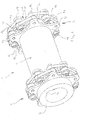
- FIGS. 1 to 3 Reference is made, in which a first embodiment of a double-torsional clutch is shown, as used between a transmission and a driven wheelset shaft of rail vehicles. It is indicated overall by the reference numeral 1. It comprises two torsion clutches 2, 3 of essentially identical construction, which are connected to one another via a tubular intermediate piece 4.
- Both torsional clutches 2, 3 have an outer connecting flange 5, 6.
- the driven wheelset shaft is passed through the entire double torsion 1, ie through the first outer connecting flange 5, the first torsion 2, the connecting piece 4, the second torsion 3 and the second outer connecting flange 6.
- FIG. 1 This works on mounted on the wheelset shaft double torsion 1 with a corresponding spring on the wheelset together so that a rotationally locked connection between the wheelset and the outer connecting flange. 5 given is.
- outer connecting flange 6 has a frontal toothing 8, which meshes with a corresponding toothing on the output shaft of the transmission, not shown.
- a plurality of radially extending arms 9 are formed.
- the torsion coupling 3 On the inside, so the connector 4 facing side, the torsion coupling 3 has an inner plate-shaped connecting flange 11 which is rotationally connected to the connecting piece 4, for example, welded, is. Again, a one-piece connection would be conceivable in principle.
- the inner connecting flange 11, like the outer connecting flange 6, has a plurality of, in the present case, six, radially extending arms 12, between which free spaces 13 remain as seen in the circumferential direction.
- the tabs 14 may have any desired construction, as far as they have the elastic properties required for damping. However, preference is given to those tabs 14 which comprise an elastomeric body, in which a force-transmitting thread package is embedded.
- the basic construction of such a tab 14 is for example in the DE 35 26 273 C3 described, to which reference is made.
- each Tab 14 has two serving as fasteners, going from one to the other end side bushings 15, which serve as Verschraubungspond.
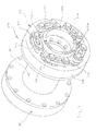
- FIGS. 4 to 6 illustrated embodiment of a double torsion coupling 101 differs essentially only in the construction of the rotation of the above-described. It comprises two torsion couplings 102, 103, which are interconnected by a connecting piece 104.
- the outer connecting flange 105 serves to connect the torsion coupling 102 to the driven Radsatzelle and the outer connecting flange 106 of the torsion coupling 103 is in rotationally connected to the output shaft of a transmission.
- Torsionskupplung 103 shown on the right, whose construction substantially coincides with that of the torsion coupling 102.
- the outer connecting flange 106 of the torsion coupling 103 like the outer connecting flange 6 of the torsion coupling 4 described above, has radially outwardly extending arms 109, but the spaces 10 between the arms 109 do not reach as deep as in the first embodiment.
- annular stop flange 117 * is arranged, which is held by circular cylindrical spacers 118 at the correct distance from the outer connecting flange 106.
- the arrangement of the outer connecting flange 106, the spacers 118 and the stop flange 117 is held together by bolts 119, which are screwed through these flanges 106, 111 into the spacers 118.
- the outer connecting flange 106 is in two parts in this Au.00: It consists of a substantially hollow cylindrical collar 106a and an attached thereto by screws annular disc 106b together, which is provided at its outer periphery with the arms 109.
- the annular stop flange 117 is provided on its inner periphery with inwardly projecting arms 120. These protrude, in particular the FIG. 4 shows, in each case in the free spaces 113 between the arms 112 of the inner connecting flange 111 a. The latter is designed in the same way as in the first embodiment and rotationally connected to the connecting piece 104.
- the stop flange 117 and the radially inside of this inner connecting flange 111 are now in a similar manner to one another by a plurality of tabs 114, as was the outer connecting flange 6 with the inner connecting flange 11 in the first embodiment: the tabs 114 each extend between an arm 112 of the inner connecting flange 11 and an arm 120 of the stop flange 117 They form in this way a kind of closed traverse, wherein the corners of this traverse are alternately on an arm 112 of the inner connecting flange 11 and an arm 120 of the stop flange 117.
- the power flow in the operation of the torsion coupling 103 is as follows: The torque is transmitted from the transmission, not shown, to the collar 106a of the outer connecting flange 106 and thus also to the disk-shaped part 106b. The power flow then continues through the bolts 119 and the spacers 118 on the stop flange 117, from there via the various tabs 114 on the inner connecting flange 111 and thus on the connecting piece 104th
- FIGS. 7 to 10 illustrated embodiment of a double-torsional coupling 201 is similar in many ways to the embodiment of the FIGS. 4 to 6 ,
- the two torsional couplings 202 and 203 are again connected to each other by an intermediate piece 204. It is sufficient to describe the torsion coupling 203, whose construction substantially coincides with the construction of the torsion coupling 202.
- the view falls on the end of the torsion coupling 203, which is connected to the transmission. Visible is in particular the outer connecting flange 206, which consists of a toothing-bearing collar 206a and an annular disc 206b (see. FIG. 10 ).
- the shape of the outer connecting flange 206 is shown in FIG FIG. 8 more clearly recognizable, since there are some components that are ready assembled in accordance with FIG. 7 to refuse the view, are removed.
- annular stop flange 217 Radially outside the disc 206b of the outer connecting flange 206 is an annular stop flange 217 with inwardly projecting arms 220.
- the stop flange 217 is in this case as the section of FIG. 10 identifies, as an angle piece formed with an axially parallel hollow cylindrical portion which is attached to the inner connecting flange 211 in a suitable manner, for example, welded or screwed.
- the inner connecting flange 211 has no arms in this embodiment itself.
- each tab 214 is secured with one end portion to one arm 220 of stop flange 218 and the other end portion to an arm 209 of outer link flange 206.
- the tabs 214 are alternately on opposite sides of the disc 106b and the stopper flange 217th
- FIGS. 7 to 9 clearly: In FIG. 7 , which corresponds to the mounted state of the torsion coupling 203, only the outer tabs 214 can be seen. In FIG. 8 a portion of these tabs 214 is removed, so that the engagement of the disc 206 b with the stopper flange 217 is better recognizable. The FIG. 9 Finally, with removed outer connecting flange 206, the "frame" of tabs 214. Finally, insbesondre is also the FIG. 10 to see how the tabs 214 are arranged alternately inside and outside of the disc 206b and the stop flange 217th
- the in the FIGS. 11 to 14 shown double torsion coupling 301 has two interconnected via an intermediate piece 304 torsional couplings 302 and 303.
- Each of these torsional couplings 302 and 303 in a sense, as will become apparent hereinafter, a Doubling of the torsion couplings 202, 203 of the FIGS. 7 to 9 represents.
- the torsion coupling 303 comprises two to its center plane, which is perpendicular to the axis, substantially symmetrical single couplings 303a, 303b.
- the construction of in FIG. 14 right single clutch 303a is almost completely consistent with the design of the torsion coupling 203, the above with reference to FIGS. 7 to 10 is described.
- a first difference is that the outer connecting flange 306 of the embodiment according to the FIGS. 11 to 14 one piece and not composed of a separate collar and a separate disc.
- the inner connecting flange 211 of the above-described embodiment of a torsion coupling 203 is omitted.
- the second single clutch 303b follows in a mirror-image arrangement.
- the single clutch 303b has the inner connecting flange 311 connected to the connecting piece 304, which corresponds to the outer connecting flange 306 of the single clutch 303a.
- Both individual clutches 303a and 303b are interconnected in terms of their forces in that the axially parallel hollow cylindrical regions of the stop flanges 317a and 317b are fastened to each other by means of bolts. In FIG. 14 Only the through holes for these bolts can be seen.
- the power flow in the torsion coupling 303 is as follows:
- the introduced from the transmission, not shown in the outer connecting flange 306 torque is in the manner already described several times via the tabs 314a in the stop flange 317a of the single clutch 303a, from there to the stop flange 317b of the single clutch 303b and continue on the tabs 314b on the inner connecting flange 311 and finally transferred into the connecting piece 304.
- the interlocking arms 309a and 320a of the outer connecting flange 306 and the stop flange 318a form a first anti-rotation device for emergencies.
- the interlocking arms 309b and 320b of the inner connecting flange 311 and the stopper flange 318b form a second anti-rotation lock.
- annular disc 422 is screwed, which extends in the radial direction inwardly to close to the collar 406a of the outer connecting flange 406.
Landscapes
- Engineering & Computer Science (AREA)
- General Engineering & Computer Science (AREA)
- Mechanical Engineering (AREA)
- Mechanical Operated Clutches (AREA)
Applications Claiming Priority (1)
| Application Number | Priority Date | Filing Date | Title |
|---|---|---|---|
| DE102012002757A DE102012002757A1 (de) | 2012-02-11 | 2012-02-11 | Elastische Torsionskupplung |
Publications (1)
| Publication Number | Publication Date |
|---|---|
| EP2626580A2 true EP2626580A2 (fr) | 2013-08-14 |
Family
ID=47603320
Family Applications (1)
| Application Number | Title | Priority Date | Filing Date |
|---|---|---|---|
| EP13151404.4A Withdrawn EP2626580A2 (fr) | 2012-02-11 | 2013-01-16 | Couplage de torsion élastique |
Country Status (2)
| Country | Link |
|---|---|
| EP (1) | EP2626580A2 (fr) |
| DE (1) | DE102012002757A1 (fr) |
Cited By (6)
| Publication number | Priority date | Publication date | Assignee | Title |
|---|---|---|---|---|
| DE102014213010A1 (de) | 2014-07-04 | 2016-01-07 | Zf Friedrichshafen Ag | Getriebe für den Antriebsstrang eines Schienenfahrzeugs |
| WO2016046020A1 (fr) * | 2014-09-25 | 2016-03-31 | Sueddeutsche Gelenkscheibenfabrik Gmbh & Co. Kg | Dispositif d'articulation à armature métallique et dispositif d'accouplement pour un mécanisme d'entraînement de véhicule |
| WO2017009141A1 (fr) * | 2015-07-15 | 2017-01-19 | Sueddeutsche Gelenkscheibenfabrik Gmbh & Co. Kg | Élément d'accouplement élastique |
| US10670081B2 (en) | 2014-09-25 | 2020-06-02 | Sueddeutsche Gelenkscheibenfabrik Gmbh & Co. Kg | Coupling device |
| ES2906523A1 (es) * | 2020-10-14 | 2022-04-18 | Tejasa Tc S L L | Acoplamiento elastico |
| CN120588190A (zh) * | 2025-08-08 | 2025-09-05 | 中科芯微智能装备(沈阳)有限公司 | 一种紧凑型真空机械手 |
Families Citing this family (3)
| Publication number | Priority date | Publication date | Assignee | Title |
|---|---|---|---|---|
| DE102014018842A1 (de) | 2014-12-17 | 2016-06-23 | Süddeutsche Gelenkscheibenfabrik GmbH & Co. KG | Kupplungsvorrichtung und fadenverstärkte Gelenkvorrichtung |
| DE102019205768A1 (de) * | 2019-04-23 | 2020-10-29 | Siemens Mobility GmbH | Anordnung zur Verbindung von Antriebsseiten eines Antriebsstrangs |
| DE102019003736A1 (de) * | 2019-05-28 | 2020-12-03 | Süddeutsche Gelenkscheibenfabrik GmbH & Co. KG | Kupplungsvorrichtung |
Family Cites Families (8)
| Publication number | Priority date | Publication date | Assignee | Title |
|---|---|---|---|---|
| US1316903A (en) * | 1919-09-23 | of youngstqww | ||
| FR1475431A (fr) * | 1965-09-11 | 1967-03-31 | Brown | Articulation à la cardan pour l'accouplement de deux arbres |
| DE3514124A1 (de) * | 1984-09-14 | 1986-03-20 | Thyssen Industrie Ag, 4300 Essen | Kardanische doppelkupplung |
| DE3526273C3 (de) * | 1985-07-23 | 1992-12-10 | Flender A F & Co | Laschenkupplung |
| JPH0752427Y2 (ja) | 1986-11-07 | 1995-11-29 | 東洋ゴム工業株式会社 | 高負荷トルク伝達用弾性継手 |
| US5163876A (en) * | 1990-07-30 | 1992-11-17 | Kop-Flex, Inc. | Method of constructing a composite flexible coupling element |
| DE4304274C1 (de) | 1993-02-12 | 1994-03-17 | Sgf Gmbh & Co Kg | Gelenkscheibe, insbesondere für den Antriebsstrang in Kraftfahrzeugen |
| DE102008047596A1 (de) | 2008-09-17 | 2010-03-25 | SGF SüDDEUTSCHE GELENKSCHEIBENFABRIK GMBH & CO. KG | Elastischer Gelenkkörper |
-
2012
- 2012-02-11 DE DE102012002757A patent/DE102012002757A1/de not_active Withdrawn
-
2013
- 2013-01-16 EP EP13151404.4A patent/EP2626580A2/fr not_active Withdrawn
Cited By (11)
| Publication number | Priority date | Publication date | Assignee | Title |
|---|---|---|---|---|
| DE102014213010A1 (de) | 2014-07-04 | 2016-01-07 | Zf Friedrichshafen Ag | Getriebe für den Antriebsstrang eines Schienenfahrzeugs |
| US10428903B2 (en) | 2014-07-04 | 2019-10-01 | Zf Friedrichshafen Ag | Transmission for the powertrain of a rail vehicle |
| WO2016046020A1 (fr) * | 2014-09-25 | 2016-03-31 | Sueddeutsche Gelenkscheibenfabrik Gmbh & Co. Kg | Dispositif d'articulation à armature métallique et dispositif d'accouplement pour un mécanisme d'entraînement de véhicule |
| US10400828B2 (en) | 2014-09-25 | 2019-09-03 | Siemens Mobility GmbH | Thread-reinforced joint device and coupling device for a vehicle drive |
| US10648513B2 (en) | 2014-09-25 | 2020-05-12 | Siemens Mobility GmbH | Thread-reinforced joint device and coupling device for a vehicle drive |
| US10670081B2 (en) | 2014-09-25 | 2020-06-02 | Sueddeutsche Gelenkscheibenfabrik Gmbh & Co. Kg | Coupling device |
| WO2017009141A1 (fr) * | 2015-07-15 | 2017-01-19 | Sueddeutsche Gelenkscheibenfabrik Gmbh & Co. Kg | Élément d'accouplement élastique |
| ES2906523A1 (es) * | 2020-10-14 | 2022-04-18 | Tejasa Tc S L L | Acoplamiento elastico |
| WO2022079334A1 (fr) * | 2020-10-14 | 2022-04-21 | Tejasa-Tc, S.L.L. | Couplage élastique |
| CN120588190A (zh) * | 2025-08-08 | 2025-09-05 | 中科芯微智能装备(沈阳)有限公司 | 一种紧凑型真空机械手 |
| CN120588190B (zh) * | 2025-08-08 | 2025-10-10 | 中科芯微智能装备(沈阳)有限公司 | 一种紧凑型真空机械手 |
Also Published As
| Publication number | Publication date |
|---|---|
| DE102012002757A1 (de) | 2013-08-14 |
Similar Documents
| Publication | Publication Date | Title |
|---|---|---|
| EP2626580A2 (fr) | Couplage de torsion élastique | |
| EP3078871B1 (fr) | Couplage de torsion double elastique | |
| DE112008002225B4 (de) | Drehschwingungsdämpfer | |
| WO2008019641A1 (fr) | Amortisseur de vibrations torsionnelles | |
| DE102014014493A1 (de) | Fadenverstärkte Gelenkvorrichtung und Kupplungsvorrichtung für einen Fahrzeugantrieb | |
| DE102014014490A1 (de) | Kupplungsvorrichtung | |
| WO2014016269A1 (fr) | Dispositif d'accouplement pour relier deux segments d'arbre avec système de liaison à chevauchement radial | |
| EP3707401B1 (fr) | Dispositif de couplage | |
| DE202013010525U1 (de) | Elastischer Gelenkkörper | |
| EP4143453B1 (fr) | Accouplement double extensible pour le raccordement de deux arbres avec compensation de décalage | |
| WO2012119714A1 (fr) | Accouplement axial renforcé par fil | |
| DE10127184A1 (de) | Flexible Wellenkupplung für Fahrzeuge | |
| DE102012214165A1 (de) | Differenzial | |
| DE102021122706B3 (de) | Drehschwingungsdämpferanordnung mit Nabeninneren Verbindungselementen | |
| DE19950597A1 (de) | Antriebsanordnung | |
| DE202013006950U1 (de) | Kupplungsvorrichtung für Industrie- oder Fahrzeuganwendungen | |
| DE102011111072A1 (de) | Kupplungsvorrichtung, insbesondere für Industrieanwendungen | |
| WO2013023743A1 (fr) | Dispositif d'accouplement, en particulier pour applications industrielles | |
| DE102013018534A1 (de) | Kupplungsmodul für eine Kupplungsvorrichtung, insbesondere für Industrieanwendungen | |
| DE102012001139B4 (de) | Verfahren zur Herstellung eines elastischen Drehverbindungselements sowie elastisches Drehverbindungselement, insbesondere elastische Torsionskupplung oder elastische Gelenkscheibe | |
| WO2025061591A1 (fr) | Couplage de compensation pour liaison de compensation de décalage de deux arbres | |
| EP2565480A1 (fr) | Elément mécanique de couplage ou d'embrayage | |
| DE102012025737B3 (de) | Elastische Doppel-Torsionskupplung | |
| DE102023121202A1 (de) | Planetengetriebe mit spielbehafteter Hohlradbefestigung | |
| DE102020202162A1 (de) | Ausgleichskupplung |
Legal Events
| Date | Code | Title | Description |
|---|---|---|---|
| PUAI | Public reference made under article 153(3) epc to a published international application that has entered the european phase |
Free format text: ORIGINAL CODE: 0009012 |
|
| AK | Designated contracting states |
Kind code of ref document: A2 Designated state(s): AL AT BE BG CH CY CZ DE DK EE ES FI FR GB GR HR HU IE IS IT LI LT LU LV MC MK MT NL NO PL PT RO RS SE SI SK SM TR |
|
| AX | Request for extension of the european patent |
Extension state: BA ME |
|
| 19A | Proceedings stayed before grant |
Effective date: 20130925 |
|
| 19F | Resumption of proceedings before grant (after stay of proceedings) |
Effective date: 20151201 |
|
| STAA | Information on the status of an ep patent application or granted ep patent |
Free format text: STATUS: THE APPLICATION HAS BEEN WITHDRAWN |
|
| 18W | Application withdrawn |
Effective date: 20151203 |