EP2626582A2 - Embrayage double - Google Patents
Embrayage double Download PDFInfo
- Publication number
- EP2626582A2 EP2626582A2 EP13002479.7A EP13002479A EP2626582A2 EP 2626582 A2 EP2626582 A2 EP 2626582A2 EP 13002479 A EP13002479 A EP 13002479A EP 2626582 A2 EP2626582 A2 EP 2626582A2
- Authority
- EP
- European Patent Office
- Prior art keywords
- clutch
- actuating
- partial
- drive
- transmission
- Prior art date
- Legal status (The legal status is an assumption and is not a legal conclusion. Google has not performed a legal analysis and makes no representation as to the accuracy of the status listed.)
- Withdrawn
Links
Images




Classifications
-
- F—MECHANICAL ENGINEERING; LIGHTING; HEATING; WEAPONS; BLASTING
- F16—ENGINEERING ELEMENTS AND UNITS; GENERAL MEASURES FOR PRODUCING AND MAINTAINING EFFECTIVE FUNCTIONING OF MACHINES OR INSTALLATIONS; THERMAL INSULATION IN GENERAL
- F16D—COUPLINGS FOR TRANSMITTING ROTATION; CLUTCHES; BRAKES
- F16D25/00—Fluid-actuated clutches
- F16D25/10—Clutch systems with a plurality of fluid-actuated clutches
-
- F—MECHANICAL ENGINEERING; LIGHTING; HEATING; WEAPONS; BLASTING
- F16—ENGINEERING ELEMENTS AND UNITS; GENERAL MEASURES FOR PRODUCING AND MAINTAINING EFFECTIVE FUNCTIONING OF MACHINES OR INSTALLATIONS; THERMAL INSULATION IN GENERAL
- F16D—COUPLINGS FOR TRANSMITTING ROTATION; CLUTCHES; BRAKES
- F16D21/00—Systems comprising a plurality of actuated clutches
- F16D21/02—Systems comprising a plurality of actuated clutches for interconnecting three or more shafts or other transmission members in different ways
- F16D21/06—Systems comprising a plurality of actuated clutches for interconnecting three or more shafts or other transmission members in different ways at least two driving shafts or two driven shafts being concentric
-
- F—MECHANICAL ENGINEERING; LIGHTING; HEATING; WEAPONS; BLASTING
- F16—ENGINEERING ELEMENTS AND UNITS; GENERAL MEASURES FOR PRODUCING AND MAINTAINING EFFECTIVE FUNCTIONING OF MACHINES OR INSTALLATIONS; THERMAL INSULATION IN GENERAL
- F16D—COUPLINGS FOR TRANSMITTING ROTATION; CLUTCHES; BRAKES
- F16D21/00—Systems comprising a plurality of actuated clutches
- F16D21/02—Systems comprising a plurality of actuated clutches for interconnecting three or more shafts or other transmission members in different ways
- F16D21/06—Systems comprising a plurality of actuated clutches for interconnecting three or more shafts or other transmission members in different ways at least two driving shafts or two driven shafts being concentric
- F16D2021/0607—Double clutch with torque input plate in-between the two clutches, i.e. having a central input plate
-
- F—MECHANICAL ENGINEERING; LIGHTING; HEATING; WEAPONS; BLASTING
- F16—ENGINEERING ELEMENTS AND UNITS; GENERAL MEASURES FOR PRODUCING AND MAINTAINING EFFECTIVE FUNCTIONING OF MACHINES OR INSTALLATIONS; THERMAL INSULATION IN GENERAL
- F16D—COUPLINGS FOR TRANSMITTING ROTATION; CLUTCHES; BRAKES
- F16D21/00—Systems comprising a plurality of actuated clutches
- F16D21/02—Systems comprising a plurality of actuated clutches for interconnecting three or more shafts or other transmission members in different ways
- F16D21/06—Systems comprising a plurality of actuated clutches for interconnecting three or more shafts or other transmission members in different ways at least two driving shafts or two driven shafts being concentric
- F16D2021/0669—Hydraulically actuated clutches with two clutch plates
-
- F—MECHANICAL ENGINEERING; LIGHTING; HEATING; WEAPONS; BLASTING
- F16—ENGINEERING ELEMENTS AND UNITS; GENERAL MEASURES FOR PRODUCING AND MAINTAINING EFFECTIVE FUNCTIONING OF MACHINES OR INSTALLATIONS; THERMAL INSULATION IN GENERAL
- F16D—COUPLINGS FOR TRANSMITTING ROTATION; CLUTCHES; BRAKES
- F16D25/00—Fluid-actuated clutches
- F16D25/08—Fluid-actuated clutches with fluid-actuated member not rotating with a clutching member
- F16D25/082—Fluid-actuated clutches with fluid-actuated member not rotating with a clutching member the line of action of the fluid-actuated members co-inciding with the axis of rotation
- F16D25/085—Fluid-actuated clutches with fluid-actuated member not rotating with a clutching member the line of action of the fluid-actuated members co-inciding with the axis of rotation the clutch actuation being of the pull type
-
- F—MECHANICAL ENGINEERING; LIGHTING; HEATING; WEAPONS; BLASTING
- F16—ENGINEERING ELEMENTS AND UNITS; GENERAL MEASURES FOR PRODUCING AND MAINTAINING EFFECTIVE FUNCTIONING OF MACHINES OR INSTALLATIONS; THERMAL INSULATION IN GENERAL
- F16D—COUPLINGS FOR TRANSMITTING ROTATION; CLUTCHES; BRAKES
- F16D25/00—Fluid-actuated clutches
- F16D25/08—Fluid-actuated clutches with fluid-actuated member not rotating with a clutching member
- F16D25/082—Fluid-actuated clutches with fluid-actuated member not rotating with a clutching member the line of action of the fluid-actuated members co-inciding with the axis of rotation
- F16D25/087—Fluid-actuated clutches with fluid-actuated member not rotating with a clutching member the line of action of the fluid-actuated members co-inciding with the axis of rotation the clutch being actuated by the fluid-actuated member via a diaphragm spring or an equivalent array of levers
-
- Y—GENERAL TAGGING OF NEW TECHNOLOGICAL DEVELOPMENTS; GENERAL TAGGING OF CROSS-SECTIONAL TECHNOLOGIES SPANNING OVER SEVERAL SECTIONS OF THE IPC; TECHNICAL SUBJECTS COVERED BY FORMER USPC CROSS-REFERENCE ART COLLECTIONS [XRACs] AND DIGESTS
- Y02—TECHNOLOGIES OR APPLICATIONS FOR MITIGATION OR ADAPTATION AGAINST CLIMATE CHANGE
- Y02T—CLIMATE CHANGE MITIGATION TECHNOLOGIES RELATED TO TRANSPORTATION
- Y02T10/00—Road transport of goods or passengers
- Y02T10/60—Other road transportation technologies with climate change mitigation effect
Definitions
- the present invention relates to a dual clutch, which is particularly useful in trucks.
- Double clutches are used in vehicles to allow a load circuit.
- a dual clutch arrangement is for example from the EP 0 185 176 B1 known and has a first part clutch K1 and a second part clutch K2.
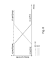
- both partial clutches K1 and K2 in the ground state are open (“Normally Open") and are pressed over at least one actuator. Then, the normally alternating applied actuating forces necessary for pressing must be applied in the same direction. The actuating forces must then be absorbed by a support bearing on the crankshaft or in the gearbox. The resulting in such an arrangement forces are the in Fig. 8 shown diagram removable.
- the partial clutch K1 is initially open, the partial clutch K2 is initially closed. The total operating force is therefore equal to the operating force of the partial clutch K2. Subsequently, an overlapping circuit is performed to close the sub-clutch K1 and open the sub-clutch K2.
- the operating force of the sub-clutch K1 increases and the operating force of the sub-clutch K2 decreases.
- the total operating force remains essentially the same.
- the partial clutch K1 is closed and the partial clutch K2 open.
- the total operating force corresponds to the operating force of the partial clutch 1.
- the total operating force remains essentially the same over the entire period.
- the partial clutch K1 in the ground state is closed ("Normally Closed") and is pressed over at least one actuator, and that the partial clutch K2 in the ground state is open (“Normally Open”) and at least one actuating device is pressed.
- the part clutch K1 closed and the part clutch K2 are open, no operating force needed.
- two actuating forces are required. In this case, add the two actuating forces and give a high axial force on the support bearing.
- Fig. 9 shown diagram removable.
- the partial clutch K1 is initially open, the partial clutch K2 is initially closed.
- the total operating force is therefore equal to the sum of the opening force of the partial clutch K1 and the closing force of the partial clutch K2.
- an overlapping circuit is performed to close the sub-clutch K1 and open the sub-clutch K2. Accordingly, the operating force of the partial clutch K1 decreases to near zero.
- the partial clutch K1 is closed and the partial clutch K2 open.
- the total operating force in turn corresponds to the sum of the actuating forces of the partial clutches K1 and K2.
- a double clutch with a first part clutch via which a drive shaft of a drive with a first transmission input shaft of a transmission is connectable and with a second part clutch via which the drive shaft of the drive with a second transmission input shaft of the transmission is connectable and with an actuating device
- the first sub-clutch K1 is closed in its unactuated state ("normally closed") and to open this first sub-clutch K1 a tensile force is applied (“pulled clutch”)
- the second sub-clutch K2 is opened in its inoperative state (“ normally open ") and a compressive force is applied to close this second partial clutch (“ depressed clutch "), so that the Actuating force of the first sub-clutch K1 against the operating force of the second sub-clutch K2 acts.
- the actuator comprises two (pressure) cylinder, wherein one of the (pressure) cylinder as a part operating means of the first part clutch K1 for forming a tensile force and a second (pressure) cylinder as a partial operating means of the second sub-coupling K2 to form a compressive force for actuation the respective partial clutches is provided.
- each of the partial actuation devices can have two separate pressure chambers.
- the aforementioned object is also achieved by a double clutch with a flywheel, which is fixedly connected to a drive shaft of a drive, wherein the double clutch further comprises a central plate as a counter-pressure plate for the pressure plates of the partial clutches, said central plate is fixed to the flywheel, and wherein the dual clutch is mounted solely on the attachment of the flywheel.
- the aforementioned object is also achieved by a double clutch with a first part clutch, via which a drive shaft of a drive with a first transmission input shaft of a Getriebes is connectable and with a second sub-coupling, via which the drive shaft of the drive with a second transmission input shaft of the transmission is connectable, wherein the double clutch has a central plate as a counter-pressure plate for the pressure plates (pressure plates) of the partial clutches, and wherein the pressure plates of both partial clutches on leaf springs, especially in connection with riveted joints, are fixed directly to the central plate.
- the aforementioned invention is also achieved by a double clutch with a flywheel (with or without vibration damping), a first part clutch K1 with clutch disc, pressure plate, lever element (in the present case designed as a plate spring) and clutch cover for supporting the lever element, via a drive shaft of a drive with a first transmission input shaft of a transmission is connectable and with a second part clutch K2 with clutch disc, pressure plate, lever element and clutch cover for supporting the lever element, via which the drive shaft of the drive with a second transmission input shaft of the transmission is connectable, wherein the double clutch, a central plate as a counter-pressure plate for the printing plates having the partial clutches, and wherein the clutch cover of the partial clutch K1 and / or the clutch cover of the partial clutch K2 are fixed by screws and centered on spacers, such as spacer tubes or Gußnocken, and these screws are stressed only to train. Accordingly, a load of the screws in the circumferential direction of the clutches can be avoided.
- a dual clutch with a flywheel with or without vibration damping
- a first part clutch K1 with clutch disc with clutch disc, pressure plate, lever element (in the present case designed as a plate spring) and clutch cover for supporting the lever element, via a drive shaft of a drive with a first transmission input shaft of a transmission is connectable and with a second part clutch K2 with clutch disc, pressure plate, lever element and clutch cover for supporting the lever element, via which the drive shaft of the drive shaft with a second transmission input shaft of the transmission is connectable
- the double clutch, a central plate as a counter pressure plate for the printing plates having the partial clutches
- the double clutch screw I with spacers such as spacer tubes or Gußnocken
- the spacers are provided for setting a defined distance between them, and wherein the central plate has openings, which of the screws of the screw connections be penetrate
- the double clutch also has further screw connections II with spacers for fixing the clutch cover of the partial clutch K1 on the pressure plate of the partial clutch K1, being provided between the clutch cover of the partial clutch K1 and the pressure plate of the partial clutch K1 spacers for setting a defined distance between them , And wherein the screws of the screw connections are screwed to the pressure plate of the partial clutch K1.
- the central plate is bolted via further screw connections III without spacers with the flywheel.
- the screws of all of the aforementioned types of bolted connections can be prestressed in accordance with the actuation force of the coupling required for torque transmission.
- the present embodiments relate to a double clutch, in particular designed for trucks (trucks).
- the dual clutch is arranged in the drive train of a vehicle between a drive and a dual clutch transmission, wherein between the drive and dual clutch, a torsion damping element, such as a dual mass flywheel, can be arranged.
- the dual clutch assembly 1 comprises a first part clutch K1, which is closed in the ground state ("normally closed”), wherein the lever mechanism of this sub-clutch K1 is formed such that this first sub-clutch K1 is subjected to a tensile force F K1 , to open them, as well a second partial clutch K2, which is open in the ground state ("normally open”), wherein the lever mechanism of this partial clutch K2 is designed such that it is acted upon for closing with a compressive force F K2 .
- One of the partial clutches K1 and K2 may have a wear adjustment device.
- both partial clutches K1 and K2 may each have wear adjusting devices.
- actuating forces tensile force F K1 of the partial clutch K1 and compressive force F K2 of the partial clutch K2
- actuating forces tensile force F K1 of the partial clutch K1 and compressive force F K2 of the partial clutch K2
- This actuating means 3 comprises a first cylinder 4 with an actuating piston 5 and pressure chambers separated from each other by this actuating piston 5, wherein one of the pressure chambers can be connected to a compressed air line 6 and the corresponding other pressure chamber can be connected to an air outlet 7.
- the air outlet 7 can be acted upon with the environment or another reservoir or with the compressed air line, if then at the same time the previous air inlet is connected to the environment, resulting in a faster operation due to the switching of the pressure level.
- FIG. 1 and Fig. 2 Shown are screw connections II spacers and screws, wherein the screws of the screw connection II are screwed to the pressure plate 12 of the partial coupling K1, and wherein the spacers in the form of spacer tubes between the pressure plate 12 and the cover 15 are braced.
- the structure of a first cylinder 4 of the actuating means 3 is such that a tensile force F K1 is exerted on the disc spring 14 of the partial clutch K1 via an actuating bearing (release bearing) 16, ie the actuating bearing 16 conveys this tensile force F K1 to the lever spring 14, which on Lid 15 is supported.
- An outer end of the lever spring 14 (plate spring 14) is mounted on the lid K1.
- a middle region of the lever spring 14 is supported on the cover 17 of the partial clutch 17.
- the actuating means 3 also comprises a second part operating means, which is also designed as a cylinder 21 having a piston 22 and two pressure chambers, which are separated from each other by the piston 22, wherein in turn one of the pressure chambers with a compressed air line 23 and another with an outlet 7 are connectable, and wherein these compounds (as in the first part operating means 4, 5) in the form of a multi-way valve (in particular three-way valve) is possible, one of the ways with the compressed air line and the other two ways with the respective Pressure chambers are connectable.
- a second part operating means which is also designed as a cylinder 21 having a piston 22 and two pressure chambers, which are separated from each other by the piston 22, wherein in turn one of the pressure chambers with a compressed air line 23 and another with an outlet 7 are connectable, and wherein these compounds (as in the first part operating means 4, 5) in the form of a multi-way valve (in particular three-way valve) is possible, one of the ways with the compressed air line and the other two ways with
- the second cylinder 21 is constructed such that a pressure force F K2 is generated, which is mediated via the actuating bearing 24 (engagement bearing) to the lever spring 13.
- the outer region of the lever spring 13 is supported on the cover 17 of the partial clutch K2, which is supported by the spacers 8 of the screw I to the central plate 10 and secured to the flywheel 11 via the screws 9 of the screw connection I.
- the cover 17 is thus supported by the spacers 8 of the screw connection I to the central plate 10 and fixed by means of the screws 9 of the screw connection I to the flywheel 11, i. the screws 9 of the screw connection penetrate passages in the central plate 10 and are screwed to the flywheel 11.
- the spacers 8 are formed as spacer tubes, wherein the screws 9 are received in the spacer tubes.
- Fig. 2 shows the double clutch 1 in the assembled state.
- Fig. 3 shows a schematic representation of the dual clutch 1 as a section in the region of the screw connection I between the cover 17 of the partial clutch K2 and central plate 10 and flywheel 11 and Fig. 4 shows a section in the region of the connection between the cover 15 of the partial clutch K1 and pressure plate (pressure plate) 12 of the partial clutch K1 via the screw connections II.
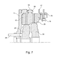
- Fig. 6 and Fig. 7 Show rivet connections, which via leaf spring assemblies 26, 27, the two pressure plates 12, 25 of the partial clutches K1 and K2 each with the common central plate 10 connect. These leaf spring assemblies 26, 27 are arranged on mutually corresponding positions on different sides of the central plate 10. The opposing leaf spring assemblies 26, 27 are each, as shown Fig. 7 can be seen at the corresponding other end via a common rivet 28 connected to the central plate 10.
- the covers 15, 17 of the partial clutches K1 and K2 are fixed by screws and centered and spaced by spacer tubes, so that the screws are loaded only to train and no moment must be transmitted.
- These spacer tubes can also be replaced by Gußnocken on the central plate.
- the dual clutch 1 is bolted to the flywheel 11 and supported exclusively on the crankshaft bearing 29.
- the actuator 3 of the dual clutch 1 has a central release and a central release each with pneumatic or hydraulic actuation. Due to the selected directions of force, the actuating forces of the clutch K1 and the actuating forces of the clutch K2 are opposite to each other, so that no axial force is transmitted to the crankshaft.
- the partial clutch K1 is closed in the ground state and must be pulled to open it and the partial clutch K2 is open in the ground state and must be pressed to close, again so that the actuating forces K1 and K2 counteract each other and an axial Force on the crankshaft can be avoided.
- the above description discloses, inter alia, that the two actuation forces of a double clutch, once the actuation force of the pushed "normally open” clutch and once the actuation force of the pulled “normally closed” clutch, balance so that the sum of the two actuation forces is almost zero, and an oversizing of the crankshaft bearing or the gearbox bearing is not required.
- the above description discloses that the partial clutch K1 in the basic state is closed (“normally closed”) is formed and to open a tensile force is applied (“pulled”), and that at the same time the partial clutch K2 in the ground state open (“Normally Open”) formed is and is applied to close a compressive force ("pressed").
- Fig. 10 a diagram is shown showing the course of the actuating forces in the present double clutch in a cross-over circuit.
- the partial clutch K1 is initially open and the partial clutch K2 is initially closed, wherein the actuating forces of the partial clutches K1 and K2 are directed counter to each other.
- the total operating force is therefore almost zero.
- an overlapping circuit is performed to close the sub-clutch K1 and open the sub-clutch K2.
- the operating force of the sub-clutch K1 increases and the operating force of the sub-clutch K2 decreases.
- the total operating force therefore remains essentially zero.
- the partial clutch K1 is closed and the partial clutch K2 open.
- Another particular advantage of the double clutch described above is that the partial clutch K1 closes by their own disc spring force, and that the partial clutch K2 opens by their own leaf spring force.
- the above description also discloses a central pneumatic double release, wherein one cylinder is provided for pushing the partial clutch K2 and another for pulling the partial clutch K1, and wherein the two cylinders are arranged axially.
- the dual clutch is bolted to the flywheel and is supported solely on the crankshaft bearing.
- the torque transmission takes place only between the pressure plates of the partial clutches K1 and K2 on the one hand and the intermediate plate on the other hand via leaf springs.
- Double coupling 2 axis of rotation 3 actuating means 4 cylinder 5 actuating piston 6 Compressed air line 7 air outlet 8th spacers 9 screw 10 Central plate 11 flywheel 12 printing plate 13 lever spring 14 Belleville spring 15 cover 16 operation seat 17 cover 18 Bearing 20 clutch disc 21 cylinder 22 piston 23 Compressed air line 25 printing plates 26 Leaf spring assembly 27 Leaf spring assembly 28 rivet 29 crankshaft bearing F K1 traction F K2 thrust K1 first part clutch K2 second part clutch
Landscapes
- Engineering & Computer Science (AREA)
- General Engineering & Computer Science (AREA)
- Mechanical Engineering (AREA)
- Mechanical Operated Clutches (AREA)
- Hydraulic Clutches, Magnetic Clutches, Fluid Clutches, And Fluid Joints (AREA)
Applications Claiming Priority (3)
| Application Number | Priority Date | Filing Date | Title |
|---|---|---|---|
| DE102008039358 | 2008-08-22 | ||
| DE102008063749 | 2008-12-18 | ||
| EP09807899.1A EP2326851B2 (fr) | 2008-08-22 | 2009-08-03 | Double embrayage |
Related Parent Applications (3)
| Application Number | Title | Priority Date | Filing Date |
|---|---|---|---|
| EP09807899.1 Division | 2009-08-03 | ||
| EP09807899.1A Division-Into EP2326851B2 (fr) | 2008-08-22 | 2009-08-03 | Double embrayage |
| EP09807899.1A Division EP2326851B2 (fr) | 2008-08-22 | 2009-08-03 | Double embrayage |
Publications (2)
| Publication Number | Publication Date |
|---|---|
| EP2626582A2 true EP2626582A2 (fr) | 2013-08-14 |
| EP2626582A3 EP2626582A3 (fr) | 2017-10-25 |
Family
ID=41256092
Family Applications (2)
| Application Number | Title | Priority Date | Filing Date |
|---|---|---|---|
| EP13002479.7A Withdrawn EP2626582A3 (fr) | 2008-08-22 | 2009-08-03 | Embrayage double |
| EP09807899.1A Active EP2326851B2 (fr) | 2008-08-22 | 2009-08-03 | Double embrayage |
Family Applications After (1)
| Application Number | Title | Priority Date | Filing Date |
|---|---|---|---|
| EP09807899.1A Active EP2326851B2 (fr) | 2008-08-22 | 2009-08-03 | Double embrayage |
Country Status (5)
| Country | Link |
|---|---|
| US (1) | US9175734B2 (fr) |
| EP (2) | EP2626582A3 (fr) |
| CN (1) | CN102132058B (fr) |
| DE (2) | DE112009001808A5 (fr) |
| WO (1) | WO2010020207A1 (fr) |
Cited By (1)
| Publication number | Priority date | Publication date | Assignee | Title |
|---|---|---|---|---|
| WO2018113836A1 (fr) * | 2016-12-19 | 2018-06-28 | Schaeffler Technologies AG & Co. KG | Débrayeur central pneumatique |
Families Citing this family (12)
| Publication number | Priority date | Publication date | Assignee | Title |
|---|---|---|---|---|
| EP2326852B1 (fr) * | 2008-08-22 | 2014-10-08 | Schaeffler Technologies GmbH & Co. KG | Ligne d'entraînement avec double embrayage |
| WO2010020206A1 (fr) * | 2008-08-22 | 2010-02-25 | Luk Lamellen Und Kupplungsbau Beteiligungs Kg | Dispositif d’actionnement pour double embrayage |
| DE202011002608U1 (de) * | 2011-02-11 | 2012-02-29 | Camera Dynamics Gmbh | Stativkopf |
| CN103307134B (zh) * | 2013-04-28 | 2015-11-18 | 长城汽车股份有限公司 | 离合器和具有该离合器的车辆 |
| WO2015164175A1 (fr) * | 2014-04-23 | 2015-10-29 | Schaeffler Technologies AG & Co. KG | Double embrayage à leviers emboîtés |
| DE102014215882A1 (de) * | 2014-08-11 | 2016-02-11 | Schaeffler Technologies AG & Co. KG | Doppelkupplung mit in Umfangsrichtung ausgerichteter und axial abstehender Lasche einer Gegendruckplatte |
| CN107735589B (zh) * | 2015-07-13 | 2020-07-07 | 舍弗勒技术股份两合公司 | 用于机动车辆的驱动系的离合器 |
| DE102015221274A1 (de) * | 2015-10-30 | 2017-05-04 | Volkswagen Aktiengesellschaft | Schaltvorrichtung und Antriebseinheit für ein Kraftfahrzeug |
| KR102238499B1 (ko) * | 2016-07-07 | 2021-04-08 | 유니프레스 가부시키가이샤 | 습식 다판 클러치 |
| DE102019100969B4 (de) * | 2019-01-16 | 2021-06-17 | Schaeffler Technologies AG & Co. KG | Trockendoppelkupplung für eine elektrische Achse sowie elektrische Achse mit der Trockendoppelkupplung |
| DE102019126188A1 (de) * | 2019-09-27 | 2021-04-01 | Schaeffler Technologies AG & Co. KG | Antriebsstrang |
| CN118188711B (zh) * | 2024-05-16 | 2024-10-18 | 陕西法士特汽车传动集团有限责任公司 | 一种干式双离合器、动力传动系统和动力系统 |
Citations (2)
| Publication number | Priority date | Publication date | Assignee | Title |
|---|---|---|---|---|
| EP0185176B1 (fr) | 1984-12-20 | 1989-03-08 | Dr.Ing.h.c. F. Porsche Aktiengesellschaft | Embrayage double pour transmission d'un véhicule automobile |
| WO2008064648A1 (fr) * | 2006-11-30 | 2008-06-05 | Luk Lamellen Und Kupplungsbau Beteiligungs Kg | Dispositif de transmission de couple |
Family Cites Families (32)
| Publication number | Priority date | Publication date | Assignee | Title |
|---|---|---|---|---|
| US2057559A (en) † | 1934-05-11 | 1936-10-13 | Backer Joseph De | Multiple clutch device |
| FR1300975A (fr) † | 1961-07-01 | 1962-08-10 | Ferodo Sa | Perfectionnements aux embrayages |
| DE1505577A1 (de) * | 1966-05-04 | 1970-07-23 | Bosch Gmbh Robert | Kupplungsvorrichtung |
| GB1233968A (fr) † | 1969-03-12 | 1971-06-03 | ||
| GB1365393A (en) † | 1971-04-13 | 1974-09-04 | Skf Uk Ltd | Clutch withdrawal bearing assemblies |
| DE2211521A1 (de) † | 1972-03-10 | 1973-09-13 | Volkswagenwerk Ag | Vorrichtung zur mechanischen kupplungsbetaetigung, insbesondere fuer kraftfahrzeugkupplungen |
| US3760918A (en) † | 1972-04-20 | 1973-09-25 | Deere & Co | Tractor pto and propulsion clutch assembly including lubrication means |
| DE2261775A1 (de) * | 1972-12-16 | 1974-06-20 | Luk Lamellen & Kupplungsbau | Reibungskupplung |
| US4069905A (en) † | 1975-02-13 | 1978-01-24 | Societe Anonyme Francaise Du Ferodo | Assembly unit for a clutch, especially for the clutches of automobile vehicles |
| DE3023294A1 (de) * | 1980-06-21 | 1982-01-07 | Fichtel & Sachs Ag, 8720 Schweinfurt | Schwungradkupplung |
| JPS59181340U (ja) † | 1983-05-20 | 1984-12-04 | 不二化学工業株式会社 | 多板式クラツチ装置 |
| FR2547882B1 (fr) † | 1983-06-22 | 1986-02-07 | Valeo | Mecanisme d'embrayage notamment pour vehicule automobile |
| GB2190714B (en) † | 1986-05-20 | 1990-06-20 | Automotive Products Plc | Friction clutches |
| FR2611838B1 (fr) † | 1987-03-06 | 1991-03-22 | Fraymon Sa | Dispositif d'actionnement d'embrayage a commande hydraulique |
| JP3193030B2 (ja) * | 1987-12-19 | 2001-07-30 | ルーク・ラメレン・ウント・クップルングスバウ・ゲゼルシヤフト・ミツト・ベシユレンクテル・ハフツング | クラッチユニット |
| DE3838865A1 (de) † | 1987-12-19 | 1989-06-29 | Luk Lamellen & Kupplungsbau | Mehrfachkupplungsaggregat |
| EP0931951B1 (fr) † | 1998-01-16 | 2000-09-13 | Ford Global Technologies, Inc. | Embrayage double à plateaux de friction, en particulier pour véhicules automobiles |
| DE19941837A1 (de) * | 1999-07-29 | 2001-02-01 | Rohs Voigt Patentverwertungsge | Kupplung, Anschlußelement sowie Anordnung hieraus und Verfahren zur Montage einer Kupplung |
| DE10012808A1 (de) * | 2000-03-16 | 2001-09-20 | Mannesmann Sachs Ag | Doppelkupplungsanordnung |
| DE10102300A1 (de) † | 2001-01-19 | 2002-07-25 | Zahnradfabrik Friedrichshafen | Zentrale Kupplungsvorrichtung |
| FR2824370B1 (fr) * | 2001-05-04 | 2003-06-27 | Valeo | Mecanisme d'embrayage a friction du type de diaphragme du genre tire commande en poussant |
| DE10149702A1 (de) * | 2001-10-09 | 2003-04-10 | Zf Sachs Ag | Mehrfach-Kupplungsanordnung |
| ATE344890T1 (de) * | 2001-10-09 | 2006-11-15 | Zf Sachs Ag | Mehrfach-kupplungsanordnung |
| ATE391863T1 (de) * | 2002-10-22 | 2008-04-15 | Zf Sachs Ag | Drehmomentübertragungsanordnung |
| DE10344124A1 (de) † | 2002-10-22 | 2004-05-06 | Zf Sachs Ag | Drehmomentübertragungsanordnung |
| DE10254900A1 (de) * | 2002-11-22 | 2004-06-03 | Zf Sachs Ag | Doppelkupplungsanordnung |
| FR2851627B1 (fr) * | 2003-02-20 | 2005-12-30 | Valeo Embrayages | Dispositif de transmission de couple pour vehicule automobile |
| FR2886996B1 (fr) | 2005-06-14 | 2007-08-17 | Valeo Embrayages | Mecanisme d'embrayages multiples avec disque de friction en 2 parties |
| EP1830095B1 (fr) * | 2006-03-02 | 2008-04-09 | C.R.F. Società Consortile per Azioni | Transmission avec embrayage double pour un véhicule automobile |
| CN104019149B (zh) * | 2007-10-15 | 2017-09-22 | 舍弗勒技术股份两合公司 | 从动缸和分离系统 |
| CN101225867B (zh) | 2008-01-29 | 2010-04-21 | 吉林大学 | 应用于干式双离合器上的两个飞轮 |
| WO2010006579A1 (fr) * | 2008-07-14 | 2010-01-21 | Luk Lamellen Und Kupplungsbau Beteiligungs Kg | Embrayage double |
-
2009
- 2009-08-03 US US13/060,195 patent/US9175734B2/en active Active
- 2009-08-03 DE DE112009001808T patent/DE112009001808A5/de not_active Withdrawn
- 2009-08-03 CN CN200980132759.2A patent/CN102132058B/zh not_active Expired - Fee Related
- 2009-08-03 WO PCT/DE2009/001085 patent/WO2010020207A1/fr not_active Ceased
- 2009-08-03 EP EP13002479.7A patent/EP2626582A3/fr not_active Withdrawn
- 2009-08-03 DE DE102009035912A patent/DE102009035912A1/de not_active Withdrawn
- 2009-08-03 EP EP09807899.1A patent/EP2326851B2/fr active Active
Patent Citations (2)
| Publication number | Priority date | Publication date | Assignee | Title |
|---|---|---|---|---|
| EP0185176B1 (fr) | 1984-12-20 | 1989-03-08 | Dr.Ing.h.c. F. Porsche Aktiengesellschaft | Embrayage double pour transmission d'un véhicule automobile |
| WO2008064648A1 (fr) * | 2006-11-30 | 2008-06-05 | Luk Lamellen Und Kupplungsbau Beteiligungs Kg | Dispositif de transmission de couple |
Cited By (1)
| Publication number | Priority date | Publication date | Assignee | Title |
|---|---|---|---|---|
| WO2018113836A1 (fr) * | 2016-12-19 | 2018-06-28 | Schaeffler Technologies AG & Co. KG | Débrayeur central pneumatique |
Also Published As
| Publication number | Publication date |
|---|---|
| EP2326851A1 (fr) | 2011-06-01 |
| EP2326851B2 (fr) | 2016-10-05 |
| EP2626582A3 (fr) | 2017-10-25 |
| CN102132058B (zh) | 2014-03-19 |
| DE112009001808A5 (de) | 2011-04-28 |
| US9175734B2 (en) | 2015-11-03 |
| US20110139565A1 (en) | 2011-06-16 |
| CN102132058A (zh) | 2011-07-20 |
| WO2010020207A1 (fr) | 2010-02-25 |
| DE102009035912A1 (de) | 2010-02-25 |
| EP2326851B1 (fr) | 2013-10-16 |
Similar Documents
| Publication | Publication Date | Title |
|---|---|---|
| EP2326851B1 (fr) | Double embrayage | |
| EP2326853B1 (fr) | Dispositif d'actionnement pour double embrayage | |
| EP2326852B1 (fr) | Ligne d'entraînement avec double embrayage | |
| EP1430230A1 (fr) | Systeme a plusieurs embrayages, en particulier a double embrayage | |
| EP2313665B1 (fr) | Procédé d'installation d'un dispositif de transmission de couple dans une chaîne cinématique d'un véhicule | |
| EP1851460B1 (fr) | Unite d'embrayage | |
| DE19539472A1 (de) | Schaltvorrichtung für Kraftfahrzeug-Wechselgetriebe - Pneumatischer Schaltservo - | |
| EP2494223B1 (fr) | Dispositif d'embrayage | |
| EP1512881B1 (fr) | Dispositif d'embrayage | |
| EP1862688B1 (fr) | Agencement de transmission d'un couple de rotation pour le conducteur de commande d'un véhicule | |
| DE102011102329A1 (de) | Doppelkupplung und Verfahren zu deren Steuerung | |
| WO2010149130A2 (fr) | Double embrayage | |
| DE19918733A1 (de) | Doppelkupplung, insbesondere für Kraftfahrzeuggetriebe | |
| EP1899629B1 (fr) | Boite de vitesses a double embrayage pour un vehicule a moteur | |
| WO2019001638A1 (fr) | Dispositif d'accouplement | |
| WO2011020457A1 (fr) | Ressort de levier | |
| DE102020210181A1 (de) | Fliehkraftkupplung für ein Fahrzeug, insbesondere für ein Elektrofahrzeug | |
| EP2753841B1 (fr) | Dispositif à embrayage | |
| DE102017217252A1 (de) | Kupplung | |
| DE102017123709A1 (de) | Doppelkupplungsvorrichtung und Antriebsanordnung für ein Kraftfahrzeug | |
| DE102016208824A1 (de) | Kupplungsaggregat und Antriebsstrang | |
| WO2007134944A1 (fr) | Embrayage à friction |
Legal Events
| Date | Code | Title | Description |
|---|---|---|---|
| PUAI | Public reference made under article 153(3) epc to a published international application that has entered the european phase |
Free format text: ORIGINAL CODE: 0009012 |
|
| AC | Divisional application: reference to earlier application |
Ref document number: 2326851 Country of ref document: EP Kind code of ref document: P |
|
| AK | Designated contracting states |
Kind code of ref document: A2 Designated state(s): AT BE BG CH CY CZ DE DK EE ES FI FR GB GR HR HU IE IS IT LI LT LU LV MC MK MT NL NO PL PT RO SE SI SK SM TR |
|
| RAP1 | Party data changed (applicant data changed or rights of an application transferred) |
Owner name: SCHAEFFLER TECHNOLOGIES GMBH & CO. KG |
|
| RAP1 | Party data changed (applicant data changed or rights of an application transferred) |
Owner name: SCHAEFFLER TECHNOLOGIES AG & CO. KG |
|
| PUAL | Search report despatched |
Free format text: ORIGINAL CODE: 0009013 |
|
| AK | Designated contracting states |
Kind code of ref document: A3 Designated state(s): AT BE BG CH CY CZ DE DK EE ES FI FR GB GR HR HU IE IS IT LI LT LU LV MC MK MT NL NO PL PT RO SE SI SK SM TR |
|
| RIC1 | Information provided on ipc code assigned before grant |
Ipc: F16D 25/08 20060101ALI20170918BHEP Ipc: F16D 21/06 20060101AFI20170918BHEP |
|
| 17P | Request for examination filed |
Effective date: 20180425 |
|
| RBV | Designated contracting states (corrected) |
Designated state(s): AT BE BG CH CY CZ DE DK EE ES FI FR GB GR HR HU IE IS IT LI LT LU LV MC MK MT NL NO PL PT RO SE SI SK SM TR |
|
| 17Q | First examination report despatched |
Effective date: 20190226 |
|
| STAA | Information on the status of an ep patent application or granted ep patent |
Free format text: STATUS: THE APPLICATION HAS BEEN WITHDRAWN |
|
| 18W | Application withdrawn |
Effective date: 20190606 |
|
| P01 | Opt-out of the competence of the unified patent court (upc) registered |
Effective date: 20230523 |