EP2628023B1 - Filterung seismischer daten auf basis eines mit einem vibrator gekoppelten bodenmodells - Google Patents
Filterung seismischer daten auf basis eines mit einem vibrator gekoppelten bodenmodells Download PDFInfo
- Publication number
- EP2628023B1 EP2628023B1 EP11833508.2A EP11833508A EP2628023B1 EP 2628023 B1 EP2628023 B1 EP 2628023B1 EP 11833508 A EP11833508 A EP 11833508A EP 2628023 B1 EP2628023 B1 EP 2628023B1
- Authority
- EP
- European Patent Office
- Prior art keywords
- ground
- source
- baseplate
- vibrator
- seismic
- Prior art date
- Legal status (The legal status is an assumption and is not a legal conclusion. Google has not performed a legal analysis and makes no representation as to the accuracy of the status listed.)
- Active
Links
Images


Classifications
-
- G—PHYSICS
- G01—MEASURING; TESTING
- G01V—GEOPHYSICS; GRAVITATIONAL MEASUREMENTS; DETECTING MASSES OR OBJECTS; TAGS
- G01V1/00—Seismology; Seismic or acoustic prospecting or detecting
- G01V1/28—Processing seismic data, e.g. for interpretation or for event detection
- G01V1/36—Effecting static or dynamic corrections on records, e.g. correcting spread; Correlating seismic signals; Eliminating effects of unwanted energy
- G01V1/37—Effecting static or dynamic corrections on records, e.g. correcting spread; Correlating seismic signals; Eliminating effects of unwanted energy specially adapted for seismic systems using continuous agitation of the ground, e.g. using pulse compression of frequency swept signals for enhancement of received signals
-
- G—PHYSICS
- G01—MEASURING; TESTING
- G01V—GEOPHYSICS; GRAVITATIONAL MEASUREMENTS; DETECTING MASSES OR OBJECTS; TAGS
- G01V1/00—Seismology; Seismic or acoustic prospecting or detecting
- G01V1/02—Generating seismic energy
- G01V1/04—Details
- G01V1/047—Arrangements for coupling the generator to the ground
- G01V1/0475—Arrangements for coupling the generator to the ground for controlling "Ground Force"
-
- G—PHYSICS
- G01—MEASURING; TESTING
- G01V—GEOPHYSICS; GRAVITATIONAL MEASUREMENTS; DETECTING MASSES OR OBJECTS; TAGS
- G01V1/00—Seismology; Seismic or acoustic prospecting or detecting
- G01V1/28—Processing seismic data, e.g. for interpretation or for event detection
- G01V1/282—Application of seismic models, synthetic seismograms
-
- G—PHYSICS
- G01—MEASURING; TESTING
- G01V—GEOPHYSICS; GRAVITATIONAL MEASUREMENTS; DETECTING MASSES OR OBJECTS; TAGS
- G01V1/00—Seismology; Seismic or acoustic prospecting or detecting
- G01V1/28—Processing seismic data, e.g. for interpretation or for event detection
-
- G—PHYSICS
- G01—MEASURING; TESTING
- G01V—GEOPHYSICS; GRAVITATIONAL MEASUREMENTS; DETECTING MASSES OR OBJECTS; TAGS
- G01V1/00—Seismology; Seismic or acoustic prospecting or detecting
- G01V1/28—Processing seismic data, e.g. for interpretation or for event detection
- G01V1/36—Effecting static or dynamic corrections on records, e.g. correcting spread; Correlating seismic signals; Eliminating effects of unwanted energy
- G01V1/364—Seismic filtering
Definitions
- seismic exploration The oil and gas exploration industry employ geophysical tools and techniques to identify a subterranean structure having potential hydrocarbon deposits.
- these techniques and tools generate an image of subsurface structures by recording energy in the form of vibrations reflected or refracted from geologic formations.
- seismic exploration for example, seismic waves generated by a source and imparted into the ground reflect off rocks in the subsurface. Boundaries between different rocks often reflect seismic waves, and information relating to these waves is collected and processed to generate a representation or images of the subsurface.
- a two-dimensional image which is called a seismic line, is essentially a cross-sectional view of the earth oriented parallel to the line of geophones.
- the information may also be collected as an intersecting grid of seismic lines referred to as a 3-D seismic volume.
- Any number of exploration systems can gather the desired information for processing.
- Dynamite explosions, vibrator trucks, air guns or the like can create the seismic waves.
- Sensors such as velocity geophones, accelerometers, and/or hydrophones can be laid out in lines, or towed in the case of hydrophones, to measure how long it takes the waves to leave the seismic source, reflect off a rock boundary, and return to the sensors used.
- An example seismic system 10 in Figure 1 can generate geophysical information to image earth subsurface structures.
- the system 10 has a central controller/recorder 90 in communication with a seismic acquisition array 12 known as a spread.
- the array 12 has spaced sensor stations 20, which can each have one or more sensors 22.
- the sensors 22 measure geophysical information and can include 3-component sensors for obtaining 3-dimensional energy known as 3D seismic.
- the sensors 22 can include accelerometers, velocity geophones, microphones, or the like, and the array 12 can be deployed on land or a seabed location.
- a seismic source 30 imparts acoustic energy into the ground, and the sensors 22 receive energy after reflection and refraction at boundaries in subsurface structures.
- the array 12 then communicates sensor data with the central controller or recorder 90 using wireless technology or other communication technique.
- the seismic source 30 can be a vibrator, such as shown in Figure 2 , although other types of sources can be used.
- the vibrator 30 transmits force to the ground using a baseplate 70 and a reaction mass 50.
- the vibrator 30 is mounted on a carrier vehicle (not shown) that uses bars 32/34 to lower the vibrator 30 to the ground. With the vibrator 30 lowered, the weight of the vehicle holds the baseplate 70 engaged with the ground so seismic source signals can be transmitted into the earth.
- the reaction mass 50 positions directly above baseplate 70 and stilts 52 extend from the baseplate 70 and through the mass 50 to stabilize it. Internally, the reaction mass 50 has a cylinder 56 formed therein. A vertically extending piston 60 extends through this cylinder 56, and a head 62 on the piston 60 divides the cylinder 56 into chambers. The ends of the piston 60 connect to cross-pieces 54U-L that connect to the stilts 52.
- Feet 36 with isolators 40 isolate the baseplate 70 from the bars 34, and tension members 42 interconnect between the feet 36 and the baseplate 70.
- the tension members 42 hold the baseplate 70 when the vibrator 30 is raised and lowered to the ground.
- shock absorbers 44 are also mounted between the bottom of the feet 36 and the baseplate 70 to isolate vibrations therebetween.
- a controller 80 receives signals from a first sensor 85 that measures acceleration of the baseplate 70 and receives signals from a second sensor 87 that measure acceleration of the reaction mass 50. Based on feedback from these sensors 85/87 and a desired sweep signal for operating the vibrator 30, the controller 80 generates a pilot signal to control a servo valve assembly 82. Driven by the drive signal, the servo valve assembly 82 alternatingly routes hydraulic fluid between a hydraulic fluid supply 84 and the piston 60. The reaction mass 50 reciprocally vibrates on the piston 60. In turn, the force generated by the vibrating mass 50 transfers to the baseplate 70 via the stilts 52 and the piston 60 so that the baseplate 70 vibrates at a desired amplitude and frequency or sweep to generate a seismic source signal into the ground.
- the moving reaction mass 50 acts upon the baseplate 70 to impart a seismic source signal into the earth, the signal travels through the ground, reflects at discontinuities and formations, and then travels toward the earth's surface.
- the array 12 of Figure 1 having the geophone receivers or other sensors 22 coupled to the ground detect the reflected signals, and the recorder 90 of Figure 1 records the seismic data 92 received from the geophone receivers 22.
- a data processing system 98 receives the seismic data 92 from the seismic recorder 90.
- the seismic data 92 can also include recorded data from the seismic vibrator 30 if information such as pilot signal, acceleration data, and weighted sum ground force are stored separately.
- the data processing system 98 can use a correlation processor to correlate the computed ground force supplied by the vibrator 30 to the seismic data 92 received by the geophone receivers 22.
- the correlated information can be used to create an image or representation of the earth's subsurface structures.
- a local sensor 85 e.g., accelerometer or geophone
- the upper cross piece 54U of the vibrator 50 which positions above the reaction mass 50.
- the controller 80 shown in Figure 2 measures the signal imparted into the ground using the local sensor 85 located on the upper cross-piece 54U and using the sensor 87 located on the reaction mass 50.
- the data processing system 98 of Figure 1 receives the seismic data 92 making up the seismic spread, it also receives the acceleration signals from these sensors 85/87 on the source 30.
- the system 98's correlation processor uses various algorithms to distinguish wave signal data from distortions and other spurious signals.
- a problem with this method is that original source signal distortion may vary and make correlation difficult.
- the results may be corrupted by unrealistic assumptions used in modeling the system 10.
- the vibrator 30 works on the surface of the ground, which can vary dramatically from location to location due to the presence of sand, rock, vegetation, etc.
- the baseplate 70 is often not evenly supported when deployed against the ground at a given location.
- the baseplate 70 will flex and directly affect the control system during operation. As a result, the radiated energy produced can vary from location to location depending on where the vibrator 30 is deployed.
- the vibrator's source signature is not the same (or nearly the same) from location to location and is not characteristically repeatable, which is desirable when performing seismic analysis.
- a more accurate knowledge of the source signal imparted into the ground by the source 30 can make the correlation easier at the data processing stage.
- the subject matter of the present disclosure is directed to overcoming, or at least reducing the effects of, one or more of the problems set forth above.
- a vibrator-coupled ground filter improves seismic data recorded during a seismic operation.
- This filter is based on a ground model that takes into consideration the vibrator system, the coupling system between the baseplate and captured ground, and the coupled ground system.
- the ground model can be used to derive particular variables for the ground model to help characterize the system.
- the recorded seismic data can be corrected to remove errors in the trace data produced by typical assumptions.
- a seismic data processing apparatus as claimed in claim 14.
- An example seismic system 10 in Figure 3 can generate geophysical information to image earth subsurface structures.
- the system 10 has a central controller/recorder 90 in communication with a seismic acquisition array 12 known as a spread.
- the array 12 has spaced sensor stations 20, which can each have one or more sensors 22.
- the sensors 22 measure geophysical information and can include 3-component sensors for obtaining 3-dimensional energy known as 3D seismic.
- the sensors 22 can include accelerometers, velocity geophones, microphones, or the like, and the array 12 can be deployed on land or a seabed location.
- a seismic source 30 imparts acoustic energy into the ground, and the sensors 22 receive energy after reflection and refraction at boundaries in earth subsurface structures.
- the seismic source 30 can be similar to the vibrator disclosed previously with reference to Figures 2 .
- the seismic source 30 according to the present disclosure need not necessarily be a hydraulically operated vibrator.
- the seismic source 30 can be a seismic vibrator have an electric motor, can have an internal or external drive, and can generate seismic shear waves (S-waves) or seismic compression waves (P-waves).
- the vibrator 30 can be any type of vibrator having a controller 80 and having a reaction mass 50 and a baseplate 70 for imparting energy into the ground.
- the moving reaction mass 50 acts upon the baseplate 70 of the vibrator 30 to impart seismic source signals into the ground.
- the signals travel through the ground, reflect at discontinuities and formations, and then travel toward the earth's surface.
- the array 12 having the geophone receivers 22 coupled to the earth detects the reflected signals, and the array 12 communicates seismic data with the central controller or recorder 90 using wireless technology or other communication technique.
- the recorder 90 records the seismic data 92 from the geophone receivers 22.
- a data processing system 98 is employed to process the seismic data 92.
- the seismic data 92 can also include recorded data from the seismic vibrator 30 if information such as pilot signal, acceleration data, and weighted sum ground force are stored separately.
- a vibrator-coupled ground filter system 94 is used to refine or improve the original seismic data 92 so that the improved data 96 can be provided to the data processing system 98.
- the data processing system 98 can use its correlation processor (not shown) to correlate a computed ground force from the information supplied by the vibrator 30 to the seismic data 96 and can ultimately provide more clear data for seismic imaging.
- the vibrator's controller 80 measures the acceleration data from local sensors.
- Part of the seismic data 92 received at the recorder 90 includes the acceleration data for both the baseplate 70 and reaction mass 50 of the vibrator 30 from such local sensors.
- the dynamic motions related to the coupling conditions of the vibrator 30 are recorded and embedded in the baseplate acceleration data.
- the motion of the vibrator's actuator e.g., hydraulic system
- the filter system 94 uses this acceleration data and a model of the coupling between the vibrator 30 and the ground to filter or correct the seismic data 92 before processing with the data processing system 98.
- the vibrator 30 works on the earth surface where the surface medium can change dramatically from location to location.
- the vibrator's baseplate 70 is coupled with the ground by applying the hold-down weight force to the baseplate 70, the baseplate 70 and the coupled ground join together and become one system. Due to the low rigidity of the baseplate 70 and variant surface conditions, the vibrator-coupled ground model can be a complex system.
- FIG 4 diagrammatically depicts a vibrator-coupled ground model 100 according to the present disclosure.
- the ground model 100 has three subsystems, which include a coupling system 110, an inhomogeneous and elastic coupled ground system 120, and a homogenous elastic deep ground 130. These subsystems express the complicated transmission of the Vibroseis wavelet from the vibrator system (30) to the ground (130).
- the vibrator-coupled ground model 100 expresses the rigidity of the baseplate 70 as part of non-ideal contact stiffness present at the boundary interaction of the baseplate 70 and the ground.
- This model 100 can serve as a more realistic representation of the vibrator-ground interaction and can describe a wide range of non-linear contact behavior (such as a partial contact and a full contact).
- the ground system 120 is described as a linear second-order system that consists of a ground mass M g , a ground stiffness K g , and a ground viscosity D g .
- the vibrator system 30 is also treated as a linear and rigid body.
- the baseplate 70 is only considered to have a mass M BP and its stiffness is distributed to become a part of the contact stiffness. Therefore, the contact stiffness in this model 100 is located in between the vibrator baseplate 70 and the ground.
- the contact stiffness here is defined as a group of “springs” (kc 1 , kc 2 , etc.) connecting the vibrator baseplate 70 and the ground 130, and the value depends on the number of "springs" (kc 1 , kc 2 , etc.) that physically connect the baseplate 70 and the ground during vibrator operation. Therefore, the contact stiffness is a variable stiffness.
- the vibrator baseplate 70 loses some contact with the ground so that the contact stiffness is reduced.
- the contact stiffness is reduced halfway through the compression cycle until halfway through the release cycle, and its value decreases as the sweep frequency increases.
- the vibrator baseplate 70 is subject to many motions such as bending, flexing, and twisting so that the contact stiffness becomes more unpredictable, and harmonic distortion becomes more severe.
- the coupling system 110 attempts to describe the coupling conditions at the interface between the baseplate 70 and the coupled ground system 120.
- the coupling system 110 can be modeled by a group of springs kc 1 , kc 2 ,...,kc n and a damper D c .
- the springs kc 1 , kc 2 ,..., kc n connect the vibrator's baseplate 70 and the coupled ground system 120 and are used to represent the variant contact stiffness in between the baseplate 70 and the coupled ground system 120 during operation of the vibrator 30.
- the baseplate's stiffness is separated as a number of small local stiffness coefficients distributed to join with these springs kc 1 , kc 2 ,...,kc n depending on the contact area between the baseplate 70 and the coupled ground.
- the damper D c represents the viscosity of the surface medium (e.g ., thin layer of vegetation or grass on the ground).
- the coupled ground system 120 in Figure 4 is described as an inhomogeneous and elastic system and can be represented by a mass-spring-damper model.
- This system 120 is inhomogeneous because the values of the captured ground mass M g , the ground stiffness K g , and the ground viscosity D g vary from location to location.
- this system 120 (and especially the captured ground mass M g ) joins with the baseplate 70 and becomes a part of the vibration source.
- the vibrator's baseplate 70 feels this coupled ground system 120, and the motion of this system 120 is embedded and detected in the baseplate acceleration data being recorded, as noted previously.
- the three parameters M g , K g , and D g of this ground coupled system 120 can be estimated using vibrator field measurements as described in more detail later. Fortunately, this system 120 can be treated as an elastic linear system because the total effect of its nonlinearities may be small and may be ignored, especially when compared to the nonlinearities existing in the vibrator hydraulic system and the nonlinearities due to low rigidity of the baseplate 70.
- the deep ground body 130 in Figure 4 is described as a homogeneous and elastic system.
- the traveled wavelet remains practically invariant.
- experimental testing can show that far-field wavelets remain invariant in deep ground and that the deep ground can be treated homogenously and elastically.
- ground model 100 All of the systems 30, 110, 120 combined together make up the vibrator-coupled ground model 100. Additional details of the ground model 100 can be found in Zhouhong Wei, "Modeling and modal analysis of seismic vibrator baseplate," Geophysical Prospecting, 58, 19-31 (2010 ).
- the block diagram of Figure 5 shows particular details to be quantified in the vibrator-coupled ground model 100 for creating a vibrator-coupled ground filter 150 for use in the purposes disclosed herein.
- the vibrator-coupled ground filter 150 of Figure 5 contains the vibrator's baseplate system 105, the coupling system 110, and the inhomogeneous elastic coupled ground system 120 expressed in formulas. This vibrator-coupled ground filter 150 is minimum phase.
- M bp is the mass of the vibrator baseplate (70)
- D c is the contact viscosity of the coupling system 110
- K c is the contact stiffness of the coupling system 110, which consists of many small springs.
- M g is the mass of the captured ground mass
- D g is the contact viscosity
- K g is the contact stiffness for the captured ground.
- the vibrator-coupled ground filter 150 is based on the transfer functions of these systems G 1 (s), G 2 (s), and G 3 (s), as well as the variables for M bp , D c , K c , M g , D g , K g , etc.
- Input 102 to the ground filter 150 includes either a pilot sweep (T ref ) or a weighted-sum ground force (W s-gf ), which are supplied by the vibrator (30).
- the weighted-sum ground force (W s-gf ) is determined by the masses M rm and M bp of the reaction mass (50) and baseplate (70), which are known, and the acceleration data Acc rm and Acc bp of the reaction mass (50) and baseplate (70) recorded at the vibrator (30).
- Output 104 of the ground filter 150 includes a filtered pilot signal (filtered T ref ) or a filtered weighted-sum ground force (filtered W s-gf ).
- This output 104 is used by the ground filter system (94) of Figure 3 to filter the seismic data (92) of the recorder (90) before processing by the data processing system (98) so that the seismic data is processed with the more accurate vibrator-captured ground model 100 of the present disclosure.
- the filtered weighted-sum ground force (filtered W s-gf ) can give better cross-correlated results between the vibrator's seismic energy and the seismic sensor responses and can reduce noise.
- the dynamic motions related to the coupling condition and the inhomogeneous and elastic coupled ground system 120 are recorded and embedded in the baseplate acceleration data Acc bp supplied by the vibrator (30) to the recorder (90).
- the motion of the vibrator's actuator e.g ., hydraulic system
- the reaction mass acceleration data Acc rm supplied by the vibrator (30) to the recorder (90).
- the vibrator measurements Acc bp and Acc rm are often recorded during data acquisition as the weighted-sum ground force (W s-gf ) using the recorder (90).
- the dynamic motions of the coupling system 110 and the coupled ground system 120 are extracted from the baseplate and reaction mass acceleration data Acc bp and Acc rm as described below.
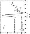
- Figure 6A shows an example frequency response for a vibrator.
- the reaction mass acceleration Acc RM is used as an input signal
- baseplate acceleration Acc BP is used as output responding to the input signal based on the ground model's transfer functions described previously.
- the frequency response of the vibrator is analyzed with the reaction mass acceleration data as input and with the baseplate acceleration as output.
- the inverse could also be done so that a frequency response can be analyzed with the baseplate acceleration data as input and with the reaction mass acceleration as output.
- the frequency responses would appear different, it is understood that the frequency response analysis can generally relate the reaction mass acceleration data and the baseplate acceleration data as input and output relative to one another.
- the magnitude plot 200A shows the magnitude ratio (dB) of Acc BP to Acc RM relative to frequency
- the phase plot 250A shows the phase (degrees) relative to frequency.
- the magnitude ratio increases at a sloped section 202 of about 40dB/dec as frequency increases.
- the magnitude ratio then reaches a turning point 204 at a resonant frequency between the baseplate (70) and the ground. Beyond this turning point 204, the magnitude ratio flattens out to a sloped section 206 of 0dB/dec.
- the phase in the phase plot 250A shifts from 0 degrees to -180 degrees. At the resonant frequency 254, the phase is expected to be -90 degrees.
- the turning point 204 is defined by the values of M g , K g , and D g in the coupled ground system (120; Figs. 3-4 ).
- the subsequent plateau section 206 is defined by the values of k c1 , k c2 , D c1 , and D c2 of the coupling system (110; Figs. 3-4 ). Knowing this theoretical nature of the frequency response having reaction mass acceleration Acc RM as input and baseplate acceleration Acc BP as output, an actual measured frequency response from measured data can be compared to the disclosed ground model 100 to derive values for M g , K g , D g , k c1-2 , D c1-2 for the vibrator-coupled ground filter 150.
- Figure 6B shows a measured frequency response using example vibrator measurement data 214 compared to model data 212 using the disclosed ground model 100.
- reaction mass acceleration data Acc rm is again used as an input signal
- baseplate acceleration data Acc bp is used as output responding to the input signal.
- the baseplate and reaction mass accelerations Acc bp and Acc rm have been measured and recorded on a standard vibrator (30) using a recorder (90).
- the measured frequency response curves 214/254 in Figure 6B are then compared to model frequency response curves 212/252 generated by the model data using the disclosed ground model 100.
- the values for the variables (M g , K g , D g ) in the ground model filter 150 are then obtained by successively modeling the measured frequency response seen in the measured data 214.
- the magnitude plot 200B the magnitude ratio spectra of the measured and model data curves 212/214 are shown.
- the phase plot 250B the corresponding phase spectra curves 262/264 are shown.
- the plots 200B/250B show that the model data curves 212/262 track the measured curves 214/264. Based on this, it can be seen that the main dynamic motions have been captured by the disclosed ground model 100, although some discrepancies are visible in these plots.
- first regions 204/254 show the main resonance produced by the baseplate (30) and the coupled ground system 110, which corresponds to flexure of the baseplate (30).
- second regions 206/256 illustrate the dynamic modes resulting from the coupling system 110.
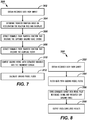
- FIG. 7 shows a process 300 for deriving the vibrator-coupled ground filter 150 of the present disclosure.
- recorded data from a survey is obtained (Block 302).
- this data includes the seismic signals obtained with the sensors (22) in the array (12) as in Figure 3 .
- this data includes the pilot signal (T ref ) and the weighted-sum ground force (W s-gf ), which includes the reaction mass and baseplate accelerations Acc bp and Acc rm .
- the acceleration data Acc bp and Acc rm for the reaction mass (50) and baseplate (70) are input into the transfer functions of the systems (i.e., G 1 (s), G 2 (s), and G 3 (s)) in the ground force model 100 (Block 304).
- the dynamic motions related to the coupling conditions are recorded and embedded in the baseplate acceleration data Acc BP .
- the motion of the vibrator's actuator system is recorded and embedded in the reaction mass acceleration data Acc RM .
- Useful information for the variables of the ground model 100 is then obtained from knowledge of the frequency response (as in Figures 6A-6B ) and the transfer functions G 1 (s), G 2 (s), and G 3 (s) for the system 100.
- variables that describe the captured ground force system 120 are extracted from the transfer functions G 1 (s), G 2 (s), and G 3 (s) (Block 306).
- These variables include M g , K g , and D g .
- the values for these variables are generally known and would be expected to lie within some target range. Yet, given the dynamic nature of the vibrator's operation, the values vary dynamically.
- the appropriate values for the variables M g , K g , and D g can be derived.
- these variables M g , K g , and D g govern the first turning point 204/254 in the frequency response of Figure 6B .
- the values for these variables M g , K g , and D g can then be derived from the first region of the frequency response.
- variables that describe the coupling system 110 are extracted from the transfer functions of the system (Block 308). These variables include kc 1-2 and Dc 1-2 . For a given vibrator, the values for these variables kc 1-2 and Dc 1-2 are generally known and would be expected to lie within some target range. Yet, given the dynamic nature of the vibrator's operation, the values vary dynamically. Using the transfer functions G 1 (s), G 2 (s), and G 3 (s) and numerical analysis, the appropriate values for the variables kc 1-2 and Dc 1-2 can be derived. In particular, these variables kc 1-2 and Dc 1-2 govern the second region 206/256 in the frequency response of Figure 6B past the turning point 204/254. Using polynomial fitting, the values for these variables kc 1-2 and Dc 1-2 can then be derived from the second region of the frequency response for the ground model 100.
- the derived values for the variables M g , K g , D g , kc 1-2 , and Dc 1-2 as well as the mass of the baseplate M BP are input into transform functions to convert the transfer functions G 1 (s), G 2 (s), and G 3 (s) into the frequency domain.
- the ground model with extracted variables is then converted into the frequency domain (Block 310) so the desired vibrator-coupled ground model filter 150 can be calculated (Block 312).
- Figure 8 shows a process 350 for using the vibrator-coupled ground filter 150 of the present disclosure.
- the array (12) and recorder (90) of Figure 3 obtain recorded data from a survey as discussed previously (Block 352).
- the seismic data (92) is to be handled by the data processing system (98).
- the system filters the original seismic data (92) with the ground filter system (94) using the vibrator-coupled ground filter 150 of the present disclosure (Block 354).
- the improved data (96) can then be provided to the data processing system (98).
- the data processing system (98) can use its correlation processor to cross-correlate survey data using the filtered pilot reference signal (filtered T ref ) or filtered weighted sum ground force (filtered W s-gf ) (Block 356).
- the system (98) can then output the cross-correlated results, which can then be used for imaging purposes (Block 358).
- the input 102 (either the pilot sweep T ref or the weighted-sum ground force W s-gf ) is injected into the vibrator-coupled ground filter 150, it is passed through transfer functions corresponding to the vibrator's baseplate system 105, the coupling system 110, and the elastic coupled ground system 120. This means that the input 102 (the pilot sweep or the weighted-sum ground force) will be sequentially filtered by these systems (105, 110, 120).
- the output 104 from the vibrator-coupled ground filter 150 becomes the filtered pilot sweep (filtered T ref ) or the filtered weighted-sum ground force (filtered W s-gf ), which is the expected input to the deep ground (130) by the vibrator 30.
- the wavelet produced by the cross-correlation function between the input 102 (pilot sweep or the weighted-sum ground force) and the output 104 (the filtered pilot sweep or the filtered weighted-sum ground force) will be indicative of an accurate wavelet that travels through the deep ground 130. It should be in phase with the downhole wavelets except for a time shift.
- the graph 400 in Figure 9 plots amplitude spectra 402 from six downhole geophones and the amplitude spectrum 404 from a filtered pilot sweep (filtered T ref ).
- the downhole geophone spectra 402 have been recorded using a standard vibrator driven by a linear sweep from 2 Hz to 160 Hz in 20 seconds. This linear sweep (pilot sweep) has been recorded as well.
- the downhole geophone spectra 402 plotted in Figure 9 are selected in 200 ft (60.96 m) intervals from 200 ft (60.96 m) to 1000 ft (304.8 m).
- the filtered pilot sweep spectrum 404 is obtained by passing the pilot sweep through the vibrator-coupled ground filter 150. It is observed that the amplitude spectrum 404 of the filtered pilot sweep (filtered T ref ) matches very well with the amplitude spectra 402 from six downhole geophones. This indicates that the filtered pilot sweep (filtered T ref ) is in the downgoing wavelet. Furthermore, the vibrator-coupled ground filter 150 does appear to accurately describe the filtering effects caused by the vibrator (30), the coupling condition between the baseplate (70) and the coupled ground, and the coupled ground system (120).
- the plot 410 in Figure 10 provides another example and shows a comparison of two wavelets 412/414.
- One wavelet 414 is produced by the cross-correlation between an original pilot sweep and the 1000 ft (304.8 m) downhole geophone data. Compensation for time delay of this wavelet 414 is made to provide a better comparison.
- the other wavelet 412 is the result of the cross-correlation function between the pilot sweep (T ref ) and the filtered pilot sweep (filtered T ref ), which is labeled as the Vibrator-Coupled Ground Model data 412 in Figure 10 .
- the two wavelets 412/414 match very well.
- the similarity of two wavelets 412/414 further confirms that the vibrator-coupled ground model 100 of the present disclosure is a reasonable model and each sub-model 110, 120, etc. can be used to represent its own system.
- Standard Vibroseis theory indicates that far-field particle velocity is proportional to a time differential of a true ground force. Again, this theory is built on an assumption that the ground can be treated as an isotropic homogeneous elastic body. As demonstrated above, the deep ground can be assumed to be a relatively homogeneous and elastic body 130, at least in the P-wave direction. However, the coupled ground system 120 of Figures 4-5 is definitely not a homogeneous body. Therefore, standard Vibroseis theory should be modified slightly to allow for the more realistic situation.
- the far-field particle velocity is proportional to the input of the deep ground 130, which is the output 104 of the pilot sweep (T ref ) or the weighted-sum ground force (W s-gf ) after it has passed through the vibrator-coupled ground model filter 150.
- Figures 11A-11B depict comparisons of wavelets generated by using the derivative of the pilot sweep (T ref ) as well as the filtered pilot sweep (filtered T ref ).
- wavelets 422/424 were obtained using the standard vibrator modeling.
- wavelets 432/434 were obtained from the modified vibrator modeling of the present disclosure.
- Curves 422/432 are produced by cross-correlating the derivatives of the pilot sweeps (T ref ) with the 1000-ft (304.8 m) downhole geophone traces.
- the curves 424/434 are results of the cross-correlation function between the filtered pilot sweeps (filtered T ref ) and the 1000-ft (304.8 m) downhole geophone traces.
- Figures 11A-11B clearly demonstrates that the zero-phase wavelets can be obtained when the filtered pilot sweep (filtered T ref ) was cross-correlated to the downhole geophone data.
- FIGS 12A-12B depict another representative example to show that the Vibrator-Coupled Ground Model 100 can describe the filtering effects seen in a Vibroseis wavelet caused by the vibrator-coupled ground system.
- These plots 440/450 depict the wavelets obtained by using the derivative of the weighted-sum ground force (W s-gf ) as well as the filtered weighted-sum ground force (filtered W s-gf ).
- W s-gf weighted-sum ground force
- filtered W s-gf filtered weighted-sum ground force
- the wavelets 442/452 are produced when the derivatives of the weighted-sum ground force (W s-gf ) was cross-correlated with the 1000-ft (304.8 m) downhole geophone traces.
- the other wavelets 444/454 are resulted from the cross-correlation of the filtered weighted-sum ground force (filtered W s-gf ) with the 1000-ft (304.8 m) downhole geophone traces.
- Figures 12A-12B show that the zero-phase wavelets can be obtained when the filtered weighted-sum ground force (filtered W s-gf ) was used to cross-correlate to the downhole geophone data. It can be observed that the wavelets in Figures 12A-12B delay slightly comparing to the wavelets in Figures 11A-11B . This tiny time-delay is due to the phase error between the pilot sweep (T ref ) and the weighted-sum ground force (W s-gf ).
- FIG. 13 shows an amplitude spectrum 460 comparing data recorded in an experimental test using a standard vibrator modeling.
- the curve 462 is produced from a surface geophone that was placed 1-m apart from the vibrator baseplate (70).
- the curve 462 represents the velocity power spectrum of particles where the surface geophone is located.
- the spectrum 460 was computed after geophone response removal.
- the baseplate accelerometer is mounted on the top cross of the baseplate stilt structure, the signal recorded by the baseplate accelerometer needs to physically pass through the baseplate (70), the coupling system (110), and the coupled ground system (120) in order to connect with any nodes in the coupled ground system (120). Additionally, because the surface geophone records the particle velocity, it makes more sense to convert the baseplate acceleration into the baseplate velocity. Therefore, the other curve 464 is calculated from the data output from the vibrator-coupled ground filter 150 where the input to the filter 150 is the baseplate velocity, which is obtained by integrating the baseplate acceleration.
- the curve 464 in the amplitude spectrum 460 obtained by utilizing the baseplate acceleration matches closely with the amplitude spectrum produced by using the surface geophone trace.
- Figure 13 indicates that the vibrator-coupled ground model 100 can simulate the filtering effects caused by the baseplate (70) and its vicinity. Moreover, it demonstrates that the coupled ground is a part of the source.
- Portions of the present disclosure may be implemented in terms of logic, software, or code typically encoded on a variety of media including, but not limited to, computer-readable media, machine-readable media, program storage media, or computer program product. Such media may be handled, read, sensed, and/or interpreted by a computing device having a processor. Those skilled in the art will appreciate that such media may take various forms such as cards, tapes, magnetic disks (e.g., floppy disk or hard drive) and optical disks (e.g., compact disk read only memory (“CD-ROM”) or digital versatile disc (“DVD”)). It should be understood that the given implementations are illustrative only and shall not limit the present disclosure.
- FIG 14 shows a geophysical information processing system 500 that can be used in accordance with the present disclosure.
- Geophysical information may be received by the geophysical information processing system 500 after being gathered by a geophysical information collector such as the collector or recorder 90 as described above and shown in Figure 3 .
- the information collector 90 can include one or more or any combination of the components shown in Figure 14 .
- the geophysical information processing system 500 may include one or more processing devices, such as a computer 520 with a storage device 510.
- the computer 500 can be, but is not limited to, a laptop computer, a desktop computer, a mainframe, or the like.
- the computer 520 may be in communication with the storage device 510 via any known interface and an interface for entering information into the computer 520 may be any acceptable interface.
- the interface may include the use of a network interface 530.
- the storage device 510 can be any useful storage device having a computer-readable media. Instructions for carrying out methods described herein may be stored on computer-readable media in the computer 520 or may be stored on an external storage device.
- Imaging includes any representation of a subsurface structure including, but not limited to, graphical representations, mathematical or numerical representation, strip charts or any other process output representative of the subsurface structure.
- Geophysical information as used herein means information relating to the location, shape, extent, depth, content, type, properties, and/or number of geologic bodies. Geophysical information includes, but is not necessarily limited to marine and land seismic information. Seismic information includes, but is not limited to, one or more or any combination of the following, analog signals, digital signals, recorded data, data structures, database information, parameters relating to surface geology, source type, source location, receiver location, receiver type, time of source activation, source duration, source frequency, energy amplitude, energy phase, energy frequency, wave acceleration, wave velocity and/or wave direction.
- Seismic information may be gathered using sensors monitoring seismic activities using, for example, a system as described above and shown in Figure 3 .
- the seismic activities result from active energy sources, including vibrator devices.
- the sensors can include geophones, accelerometers, pressure sensors, single component sensors, and/or multi-component sensors.
Landscapes
- Engineering & Computer Science (AREA)
- Remote Sensing (AREA)
- Physics & Mathematics (AREA)
- Life Sciences & Earth Sciences (AREA)
- Acoustics & Sound (AREA)
- Environmental & Geological Engineering (AREA)
- Geology (AREA)
- General Life Sciences & Earth Sciences (AREA)
- General Physics & Mathematics (AREA)
- Geophysics (AREA)
- Geophysics And Detection Of Objects (AREA)
- Investigation Of Foundation Soil And Reinforcement Of Foundation Soil By Compacting Or Drainage (AREA)
Claims (15)
- Verarbeitungsverfahren für seismische Daten, umfassend:Weiterleiten von akustischer Energie in den Boden mit einer seismischen Quelle (30), die einen Vibrator einschließt, der mit einer Reaktionsmasse (50) und einer Grundplatte (70) bereitgestellt ist;Erhalten von Reaktionsmasse-Beschleunigungsdaten der Quelle (30) seismischer Energie;Erhalten von Grundplatten-Beschleunigungsdaten der Quelle (30);Erhalten von seismischen Daten eines oder mehrerer seismischer Sensoren (22), die auf die seismische Energie der Quelle (30) reagieren;Definieren eines Bodenmodells (100), wobei das Bodenmodell (100) einen Satz von Variablen einschließt;Ableiten einer Übertragungsfunktion von dem Bodenmodell (100):Ableiten der Variablen, die im Bodenmodell (100) eingeschlossen sind, durch Analysieren einer Frequenzreaktion für den Vibrator basierend auf der Übertragungsfunktion des Bodenmodells, wobei die Frequenzreaktion die Reaktionsmasse-Beschleunigungsdaten und die Grundplatten-Beschleunigungsdaten als Eingabe und Ausgabe in Bezug aufeinander in Beziehung setzt;Filtern eines Quellensignals, das zum Betreiben der seismischen Quelle (30) konfiguriert ist, unter Verwendung der aus dem Bodenmodell (100) abgeleiteten Übertragungsfunktion mit den abgeleiteten Werten für die Variablen; undVerfügbarmachen des gefilterten Quellensignals zur Verarbeitung mit den seismischen Daten des einen oder der mehreren seismischen Sensoren (22),wobei das Verarbeitungsverfahren dadurch gekennzeichnet ist, dass das Bodenmodell (100) die Kopplung zwischen dem Vibrator und dem Boden definiert, auf dem der Vibrator platziert ist, und die Bodenmodellvariablen diese Kopplung beschreiben.
- Verfahren nach Anspruch 1, wobei das Erhalten der Reaktionsmasse-Beschleunigungsdaten das Erhalten von Messwerten eines Beschleunigungsmessers umfasst, der einer Reaktionsmasse (50) der Quelle (30) zugeordnet ist, und wobei das Erhalten der Grundplatten-Beschleunigungsdaten das Erhalten einer Auslesung eines Beschleunigungsmessers umfasst, der einer Grundplatte (70) der Quelle (30) zugeordnet ist.
- Verfahren nach Anspruch 1 oder 2, wobei das Erhalten der Reaktionsmasse (50) und der Grundplatten-Beschleunigungsdaten das Empfangen der Reaktionsmasse (50) und der Grundplatten-Beschleunigungsdaten von einer Aufzeichnungsvorrichtung umfasst, die der Quelle (30) zugeordnet ist, und wobei das Erhalten der seismischen Daten eines oder mehrerer seismischer Sensoren (22) das Empfangen der seismischen Daten von einer Aufzeichnungsvorrichtung umfasst, die dem einen oder den mehreren seismischen Sensoren (22) zugeordnet ist.
- Verfahren nach Anspruch 1, 2 oder 3, wobei das Ableiten der Variablen für das Bodenmodell (100) das Ableiten einer Masse, einer Viskosität und einer Steifigkeit von erfasstem Boden des Bodenmodells (100) basierend auf einer Resonanzfrequenz umfasst, die durch die Frequenzreaktion angezeigt wird.
- Verfahren nach einem der vorstehenden Ansprüche, wobei das Filtern des Quellensignals das Filtern einer gewichteten Summen-Bodenkraft für die Quelle (30) umfasst.
- Verfahren nach Anspruch 5, wobei die gewichtete Summen-Bodenkraft eine erste Kraft umfasst, die mit einer zweiten Kraft summiert wird, wobei die erste Kraft durch eine Masse einer Reaktionsmasse (50) der Quelle (30) multipliziert mit den Reaktionsmasse-Beschleunigungsdaten definiert wird, wobei die zweite Kraft durch eine Masse einer Grundplatte (70) der Quelle (30) multipliziert mit den Grundplatten-Beschleunigungsdaten definiert wird.
- Verfahren nach einem Ansprüche 1-4, wobei das Filtern des Quellensignals das Filtern eines Pilotsignals für die Quelle (30) umfasst.
- Verfahren nach einem der vorstehenden Ansprüche, weiter umfassend das Korrelieren der seismischen Daten mit dem gefilterten Quellensignal.
- Verfahren nach einem der vorstehenden Ansprüche, wobei das Ableiten der Variablen für das Bodenmodell (100) das Modellieren eines Grundplattensystems der Quelle in dem Bodenmodell (100) mit einer ersten Transformationsfunktion basierend auf einem Massenwert Mbp einer Grundplatte (70) der Quelle, einem Dämpfungswert Dc, der für eine Viskosität eines Oberflächenmediums steht, und auf einem Steifigkeitswert Kc basiert, das für eine Kontaktsteifigkeit des Bodenmodells (100) steht, und wobei die erste Transformationsfunktion wahlweise die folgende Form aufweist:

- Verfahren nach einem der vorstehenden Ansprüche, wobei das Ableiten der Variablen für das Bodenmodell (100) das Modellieren eines Kopplungssystems der Quelle in dem Bodenmodell (100) mit einer zweiten Transformationsfunktion basierend auf einem Dämpfungswert Dc, der für eine Viskosität eines Oberflächenmediums steht, und auf einem Steifigkeitswert Kc, das für eine Kontaktsteifigkeit des Kopplungssystems steht, umfasst, und wobei die zweite Transformationsfunktion wahlweise die folgende Form aufweist:
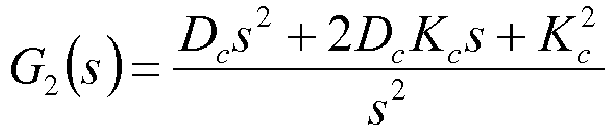
- Verfahren nach einem der vorstehenden Ansprüche, wobei das Ableiten der Variablen für das Bodenmodell (100) das Modellieren eines gekoppelten Bodensystems der Quelle in dem Bodenmodell (100) mit einer dritten Transformationsfunktion basierend auf einem Massenwert Mg von erfasstem Boden, einem Dämpfungswert Dg, der für eine Kontaktviskosität des erfassten Bodens steht, und auf einem Steifigkeitswert Kg basiert, das für eine Kontaktsteifigkeit des erfassten Bodens steht, und wobei die dritte Transformationsfunktion wahlweise die folgende Form aufweist:

- Verfahren nach einem der vorstehenden Ansprüche, wobei das Ableiten der Variablen für das Bodenmodell (100) durch Analysieren der Frequenzreaktion, welche die Reaktionsmasse-Beschleunigungsdaten und die Grundplatten-Beschleunigungsdaten als Eingabe und Ausgabe in Bezug aufeinander in Beziehung setzt, das Anwenden einer Kurvenanpassung an eine erste Region der Frequenzreaktion unterhalb einer Resonanzfrequenz einer Grundplatte (70) und des Bodens umfasst, um einen Massenwert Mg, der für eine Masse von erfasstem Boden in dem Bodenmodell (100) steht, einen Steifigkeitswert Kg, der für eine Kontaktsteifigkeit des erfassten Bodens steht, und einen Dämpfungswert Dg, das für eine Kontaktviskosität des erfassten Bodens steht, abzuleiten.
- Verfahren nach einem der vorstehenden Ansprüche, wobei das Ableiten der Variablen für das Bodenmodell (100) durch Analysieren der Frequenzreaktion, welche die Reaktionsmasse-Beschleunigungsdaten und die Grundplatten-Beschleunigungsdaten als Eingabe und Ausgabe in Bezug aufeinander in Beziehung setzt, das Anwenden einer Kurvenanpassung an eine zweite Region der Frequenzreaktion oberhalb einer Resonanzfrequenz einer Grundplatte (70) der Quelle und des Bodens umfasst, um einen Dämpfungswert Dc, der für eine Viskosität eines Oberflächenmediums steht, und einen Steifigkeitswert Kc, das für eine Kontaktsteifigkeit steht, abzuleiten.
- Verarbeitungseinrichtung für seismische Daten, umfassend:eine seismische Quelle (30), konfiguriert zum Weiterleiten von akustischer Energie in den Boden, wobei die seismische Quelle (30) einen Vibrator einschließt, der eine Reaktionsmasse (50) und eine Grundplatte (70) umfasst;einen Speicher, der ein Bodenmodell speichert, wobei das Bodenmodell einen Satz von Variablen und eine Übertragungsfunktion, ein Quellensignal, konfiguriert zum Betreiben der seismischen Quelle, Reaktionsmasse-Beschleunigungsdaten der Quelle (30), Grundplatten-Beschleunigungsdaten der Quelle (30) und seismische Daten eines oder mehrerer seismischer Sensoren (22), die auf die seismische Energie der Quelle (30) reagieren, einschließt; undeine oder mehrere Verarbeitungseinheiten, die mit dem Speicher betriebsbereit gekoppelt und konfiguriert sind zum:Analysieren einer Frequenzreaktion für den Vibrator basierend auf der Übertragungsfunktion des Bodenmodells, wobei die Frequenzreaktion die Reaktionsmasse-Beschleunigungsdaten und die Grundplatten-Beschleunigungsdaten als Eingabe und Ausgabe in Bezug aufeinander in Beziehung setzt,Ableiten der im Bodenmodell (100) eingeschlossenen Variablen basierend auf der analysierten Frequenzreaktion,Filtern des Quellensignals unter Verwendung der aus dem Bodenmodell (100) abgeleiteten Übertragungsfunktion mit den abgeleiteten Werten für die Variablen undVerfügbarmachen des gefilterten Quellensignals zum Verarbeiten mit abgeleiteten Werten für die seismischen Daten,wobei die Einrichtung dadurch gekennzeichnet ist, dass das Bodenmodell (100) die Kopplung zwischen dem Vibrator und dem Boden definiert, auf dem der Vibrator platziert ist, und die Variablen des Bodenmodells (100) diese Kopplung beschreiben.
- Einrichtung nach Anspruch 14, wobei die eine oder die mehreren Verarbeitungseinheiten betrieben werden können, um die seismischen Daten mit dem gefilterten Quellensignal zu korrelieren.
Applications Claiming Priority (2)
| Application Number | Priority Date | Filing Date | Title |
|---|---|---|---|
| US39310610P | 2010-10-14 | 2010-10-14 | |
| PCT/US2011/056409 WO2012051561A2 (en) | 2010-10-14 | 2011-10-14 | Seismic data filtering based on vibrator-coupled ground model |
Publications (3)
| Publication Number | Publication Date |
|---|---|
| EP2628023A2 EP2628023A2 (de) | 2013-08-21 |
| EP2628023A4 EP2628023A4 (de) | 2016-08-31 |
| EP2628023B1 true EP2628023B1 (de) | 2019-12-04 |
Family
ID=45939011
Family Applications (1)
| Application Number | Title | Priority Date | Filing Date |
|---|---|---|---|
| EP11833508.2A Active EP2628023B1 (de) | 2010-10-14 | 2011-10-14 | Filterung seismischer daten auf basis eines mit einem vibrator gekoppelten bodenmodells |
Country Status (5)
| Country | Link |
|---|---|
| US (1) | US8909480B2 (de) |
| EP (1) | EP2628023B1 (de) |
| CN (1) | CN103238087B (de) |
| CA (1) | CA2813782A1 (de) |
| WO (1) | WO2012051561A2 (de) |
Families Citing this family (17)
| Publication number | Priority date | Publication date | Assignee | Title |
|---|---|---|---|---|
| US20120075955A1 (en) * | 2010-09-28 | 2012-03-29 | Timothy Dean | Efficient seismic source operation in connection with a seismic survey |
| US20130201793A1 (en) * | 2012-01-13 | 2013-08-08 | Spencer Lewis Rowse | Vibrator source system for improved seismic imaging |
| EP2845035A4 (de) * | 2012-04-30 | 2015-05-13 | Conocophillips Co | Konstante energieverschiebungen |
| WO2014110565A1 (en) * | 2013-01-14 | 2014-07-17 | Inova Ltd. | Method of optimizing seismic vibrator output force |
| US9217797B2 (en) | 2013-04-11 | 2015-12-22 | Schlumberger Technology Corporation | High-speed image monitoring of baseplate movement in a vibrator |
| WO2014196858A1 (en) * | 2013-06-04 | 2014-12-11 | Mi-Partners Bv | Seismic shaker |
| WO2015101643A1 (en) * | 2013-12-30 | 2015-07-09 | Pgs Geophysical As | Control system for marine vibrators |
| US10488542B2 (en) | 2014-12-02 | 2019-11-26 | Pgs Geophysical As | Use of external driver to energize a seismic source |
| WO2018026623A1 (en) * | 2016-08-05 | 2018-02-08 | Inova Ltd. | Novel system and related methods for performing seismic surveys |
| MX367617B (es) * | 2016-10-14 | 2019-08-26 | Andres Pech Perez | Método y sistema de detección y caracterización de ondas inducidas por el flujo de fluidos, los flujos de particulas atómicas, la propagación de fracturas y la activación de fallas geológicas. |
| US10288755B2 (en) | 2017-03-28 | 2019-05-14 | Saudi Arabian Oil Company | Seismic processing workflow for broadband single-sensor single-source land seismic data |
| CN108425983B (zh) * | 2018-04-08 | 2024-03-29 | 天津大学 | 适用于振动台的多点地震动试验刚度阻尼可调边界系统 |
| CN110907992B (zh) * | 2019-12-05 | 2021-07-30 | 中国石油化工集团有限公司 | 一种基于可控震源震动感应的地表物性区分方法 |
| US11703607B2 (en) | 2020-06-15 | 2023-07-18 | Saudi Arabian Oil Company | Determining a seismic quality factor for subsurface formations from a seismic source to a first VSP downhole receiver |
| CN112305604A (zh) * | 2020-07-24 | 2021-02-02 | 中国石油化工集团有限公司 | 一种可控震源组合激发条件下的近地表物性区分方法 |
| CN113049202B (zh) * | 2021-03-08 | 2022-07-12 | 中国地震局工程力学研究所 | 一种加速度积分位移的局部加权回归校正方法及系统 |
| CN117751308A (zh) * | 2021-04-19 | 2024-03-22 | 挪威海洋反射公司 | 用于表征地震声信号的系统和方法 |
Family Cites Families (13)
| Publication number | Priority date | Publication date | Assignee | Title |
|---|---|---|---|---|
| FR1355517A (fr) | 1961-12-30 | 1964-03-20 | Inst Francais Du Petrole | Système d'asservissement pour vibrateurs |
| GB2190746B (en) | 1986-03-24 | 1990-06-13 | Bird James Mckenna | Improvements in or relating to methods of collecting data and seismic vibrators |
| US4750157A (en) * | 1987-05-06 | 1988-06-07 | Standard Oil Production Company | Seismic vibrator earth impedance determination and compensation system |
| WO1999026179A1 (en) * | 1997-11-14 | 1999-05-27 | Western Atlas International, Inc. | Seismic data acquisition and processing using non-linear distortion in a groundforce signal |
| US7206709B2 (en) * | 2003-05-29 | 2007-04-17 | Carnegie Mellon University | Determination of damping in bladed disk systems using the fundamental mistuning model |
| WO2005098731A2 (en) * | 2004-03-29 | 2005-10-20 | German Peter T | Systems and methods to determine elastic properties of materials |
| US7225662B2 (en) * | 2004-08-27 | 2007-06-05 | Schlumberger Technology Corporation | Geophone calibration technique |
| BRPI0520555B1 (pt) * | 2005-09-19 | 2017-11-14 | Micro Motion, Inc. | Electronic meter apparatus and method for determining a rigidity parameter of a flow meter |
| US7327633B2 (en) * | 2005-12-12 | 2008-02-05 | Westerneco L.L.C. | Systems and methods for enhancing low-frequency content in vibroseis acquisition |
| WO2007126786A2 (en) | 2006-03-27 | 2007-11-08 | Input/Output, Inc. | Apparatus and method for generating a seismic source signal |
| US7539079B2 (en) * | 2006-03-29 | 2009-05-26 | Pgs Geophysical As | System and method for determining positions of towed marine source-array elements |
| US20080201089A1 (en) * | 2007-01-11 | 2008-08-21 | Ensco, Inc. | System and method for determining neutral temperature of a metal |
| RU2503976C2 (ru) | 2009-05-01 | 2014-01-10 | Айнова Лтд. | Сейсмический вибратор, управляемый с прямым обнаружением перемещения плиты основания |
-
2011
- 2011-10-14 CA CA2813782A patent/CA2813782A1/en not_active Abandoned
- 2011-10-14 EP EP11833508.2A patent/EP2628023B1/de active Active
- 2011-10-14 US US13/273,997 patent/US8909480B2/en active Active
- 2011-10-14 CN CN201180055874.1A patent/CN103238087B/zh not_active Expired - Fee Related
- 2011-10-14 WO PCT/US2011/056409 patent/WO2012051561A2/en not_active Ceased
Non-Patent Citations (1)
| Title |
|---|
| None * |
Also Published As
| Publication number | Publication date |
|---|---|
| CN103238087A (zh) | 2013-08-07 |
| US20120271551A1 (en) | 2012-10-25 |
| WO2012051561A2 (en) | 2012-04-19 |
| WO2012051561A3 (en) | 2012-07-26 |
| US8909480B2 (en) | 2014-12-09 |
| EP2628023A4 (de) | 2016-08-31 |
| CA2813782A1 (en) | 2012-04-19 |
| EP2628023A2 (de) | 2013-08-21 |
| CN103238087B (zh) | 2016-05-04 |
Similar Documents
| Publication | Publication Date | Title |
|---|---|---|
| EP2628023B1 (de) | Filterung seismischer daten auf basis eines mit einem vibrator gekoppelten bodenmodells | |
| US11016211B2 (en) | 4D time shift and amplitude joint inversion for obtaining quantitative saturation and pressure separation | |
| US11428834B2 (en) | Processes and systems for generating a high-resolution velocity model of a subterranean formation using iterative full-waveform inversion | |
| JP5379163B2 (ja) | 地震探査データのスペクトルシェーピングインバージョン法及びマイグレーション法 | |
| RU2523734C2 (ru) | Система и способ сбора сейсмических данных | |
| EP3602136B1 (de) | Amplitudenkompensation von sammlungen von reverse-time-migration (rtm) zur avo/ava-analyse | |
| CA2718917C (en) | Method for imaging the earth's subsurface using passive seismic sensing | |
| CN102112894A (zh) | 用地震表面波的波形评估土壤性质 | |
| CN111025386A (zh) | 一种无分离假象的纵横波分离方法 | |
| EP2756333B1 (de) | Verbesserung einer seismischen frequenzablenkung | |
| Raji et al. | Wavefield analysis of crosswell seismic data | |
| Wei et al. | Break through the limits of vibroseis data quality | |
| Hailemikael et al. | From ambient vibration data analysis to 1D ground-motion prediction of the Mj 5.9 and the Mj 6.5 Kumamoto earthquakes in the Kumamoto alluvial plain, Japan | |
| US20080232195A1 (en) | Apparatus and Method for Processing Geophysical Information | |
| EP2722689B1 (de) | Seismische Quelle und Verfahren zur Abschwächung von Intermodulation in einer Einzelabtastung | |
| EP2722690A2 (de) | Seismische Quelle und Verfahren zur Intermodulationsabschwachung | |
| Wei | The vibrator-ground model and the vibroseis source wavelet | |
| Hu et al. | Quantitative FWI characterization of reservoir properties at the CMC Newell County Facility | |
| Sethi et al. | Finite-difference modeling for coupled acoustic-elastic anisotropic media using mimetic operators | |
| Liu et al. | Seismic Monitoring at the Farnsworth CO2-EOR Field Using Time-Lapse Elastic-Waveform Inversion of 3D-3C VSP Data. Energies 2023, 16, 3939 | |
| Song | Locating Petroleum Sources Using Dsp Techniques | |
| Luo et al. | Application of high-resolution linear Radon transform for Rayleigh-wave dispersive energy imaging and mode separating | |
| Barak et al. | Modeling ocean-bottom seismic rotation rates |
Legal Events
| Date | Code | Title | Description |
|---|---|---|---|
| PUAI | Public reference made under article 153(3) epc to a published international application that has entered the european phase |
Free format text: ORIGINAL CODE: 0009012 |
|
| 17P | Request for examination filed |
Effective date: 20130418 |
|
| AK | Designated contracting states |
Kind code of ref document: A2 Designated state(s): AL AT BE BG CH CY CZ DE DK EE ES FI FR GB GR HR HU IE IS IT LI LT LU LV MC MK MT NL NO PL PT RO RS SE SI SK SM TR |
|
| DAX | Request for extension of the european patent (deleted) | ||
| A4 | Supplementary search report drawn up and despatched |
Effective date: 20160803 |
|
| RIC1 | Information provided on ipc code assigned before grant |
Ipc: G01V 1/28 20060101ALI20160728BHEP Ipc: G01V 1/37 20060101ALI20160728BHEP Ipc: G01V 1/00 20060101AFI20160728BHEP Ipc: G01V 1/047 20060101ALI20160728BHEP Ipc: G01V 1/36 20060101ALI20160728BHEP |
|
| GRAP | Despatch of communication of intention to grant a patent |
Free format text: ORIGINAL CODE: EPIDOSNIGR1 |
|
| STAA | Information on the status of an ep patent application or granted ep patent |
Free format text: STATUS: GRANT OF PATENT IS INTENDED |
|
| INTG | Intention to grant announced |
Effective date: 20190103 |
|
| GRAJ | Information related to disapproval of communication of intention to grant by the applicant or resumption of examination proceedings by the epo deleted |
Free format text: ORIGINAL CODE: EPIDOSDIGR1 |
|
| STAA | Information on the status of an ep patent application or granted ep patent |
Free format text: STATUS: REQUEST FOR EXAMINATION WAS MADE |
|
| GRAP | Despatch of communication of intention to grant a patent |
Free format text: ORIGINAL CODE: EPIDOSNIGR1 |
|
| STAA | Information on the status of an ep patent application or granted ep patent |
Free format text: STATUS: GRANT OF PATENT IS INTENDED |
|
| INTC | Intention to grant announced (deleted) | ||
| INTG | Intention to grant announced |
Effective date: 20190614 |
|
| RIN1 | Information on inventor provided before grant (corrected) |
Inventor name: WEI, ZHOUHONG Inventor name: PHILLIPS, THOMAS |
|
| GRAS | Grant fee paid |
Free format text: ORIGINAL CODE: EPIDOSNIGR3 |
|
| GRAA | (expected) grant |
Free format text: ORIGINAL CODE: 0009210 |
|
| STAA | Information on the status of an ep patent application or granted ep patent |
Free format text: STATUS: THE PATENT HAS BEEN GRANTED |
|
| AK | Designated contracting states |
Kind code of ref document: B1 Designated state(s): AL AT BE BG CH CY CZ DE DK EE ES FI FR GB GR HR HU IE IS IT LI LT LU LV MC MK MT NL NO PL PT RO RS SE SI SK SM TR |
|
| REG | Reference to a national code |
Ref country code: GB Ref legal event code: FG4D |
|
| REG | Reference to a national code |
Ref country code: CH Ref legal event code: EP |
|
| REG | Reference to a national code |
Ref country code: AT Ref legal event code: REF Ref document number: 1210082 Country of ref document: AT Kind code of ref document: T Effective date: 20191215 |
|
| REG | Reference to a national code |
Ref country code: DE Ref legal event code: R096 Ref document number: 602011063840 Country of ref document: DE |
|
| REG | Reference to a national code |
Ref country code: IE Ref legal event code: FG4D |
|
| REG | Reference to a national code |
Ref country code: NL Ref legal event code: MP Effective date: 20191204 |
|
| REG | Reference to a national code |
Ref country code: LT Ref legal event code: MG4D |
|
| PG25 | Lapsed in a contracting state [announced via postgrant information from national office to epo] |
Ref country code: ES Free format text: LAPSE BECAUSE OF FAILURE TO SUBMIT A TRANSLATION OF THE DESCRIPTION OR TO PAY THE FEE WITHIN THE PRESCRIBED TIME-LIMIT Effective date: 20191204 Ref country code: LT Free format text: LAPSE BECAUSE OF FAILURE TO SUBMIT A TRANSLATION OF THE DESCRIPTION OR TO PAY THE FEE WITHIN THE PRESCRIBED TIME-LIMIT Effective date: 20191204 Ref country code: SE Free format text: LAPSE BECAUSE OF FAILURE TO SUBMIT A TRANSLATION OF THE DESCRIPTION OR TO PAY THE FEE WITHIN THE PRESCRIBED TIME-LIMIT Effective date: 20191204 Ref country code: LV Free format text: LAPSE BECAUSE OF FAILURE TO SUBMIT A TRANSLATION OF THE DESCRIPTION OR TO PAY THE FEE WITHIN THE PRESCRIBED TIME-LIMIT Effective date: 20191204 Ref country code: GR Free format text: LAPSE BECAUSE OF FAILURE TO SUBMIT A TRANSLATION OF THE DESCRIPTION OR TO PAY THE FEE WITHIN THE PRESCRIBED TIME-LIMIT Effective date: 20200305 Ref country code: NO Free format text: LAPSE BECAUSE OF FAILURE TO SUBMIT A TRANSLATION OF THE DESCRIPTION OR TO PAY THE FEE WITHIN THE PRESCRIBED TIME-LIMIT Effective date: 20200304 Ref country code: BG Free format text: LAPSE BECAUSE OF FAILURE TO SUBMIT A TRANSLATION OF THE DESCRIPTION OR TO PAY THE FEE WITHIN THE PRESCRIBED TIME-LIMIT Effective date: 20200304 Ref country code: FI Free format text: LAPSE BECAUSE OF FAILURE TO SUBMIT A TRANSLATION OF THE DESCRIPTION OR TO PAY THE FEE WITHIN THE PRESCRIBED TIME-LIMIT Effective date: 20191204 |
|
| PG25 | Lapsed in a contracting state [announced via postgrant information from national office to epo] |
Ref country code: RS Free format text: LAPSE BECAUSE OF FAILURE TO SUBMIT A TRANSLATION OF THE DESCRIPTION OR TO PAY THE FEE WITHIN THE PRESCRIBED TIME-LIMIT Effective date: 20191204 Ref country code: HR Free format text: LAPSE BECAUSE OF FAILURE TO SUBMIT A TRANSLATION OF THE DESCRIPTION OR TO PAY THE FEE WITHIN THE PRESCRIBED TIME-LIMIT Effective date: 20191204 |
|
| PG25 | Lapsed in a contracting state [announced via postgrant information from national office to epo] |
Ref country code: AL Free format text: LAPSE BECAUSE OF FAILURE TO SUBMIT A TRANSLATION OF THE DESCRIPTION OR TO PAY THE FEE WITHIN THE PRESCRIBED TIME-LIMIT Effective date: 20191204 |
|
| PG25 | Lapsed in a contracting state [announced via postgrant information from national office to epo] |
Ref country code: EE Free format text: LAPSE BECAUSE OF FAILURE TO SUBMIT A TRANSLATION OF THE DESCRIPTION OR TO PAY THE FEE WITHIN THE PRESCRIBED TIME-LIMIT Effective date: 20191204 Ref country code: PT Free format text: LAPSE BECAUSE OF FAILURE TO SUBMIT A TRANSLATION OF THE DESCRIPTION OR TO PAY THE FEE WITHIN THE PRESCRIBED TIME-LIMIT Effective date: 20200429 Ref country code: CZ Free format text: LAPSE BECAUSE OF FAILURE TO SUBMIT A TRANSLATION OF THE DESCRIPTION OR TO PAY THE FEE WITHIN THE PRESCRIBED TIME-LIMIT Effective date: 20191204 Ref country code: NL Free format text: LAPSE BECAUSE OF FAILURE TO SUBMIT A TRANSLATION OF THE DESCRIPTION OR TO PAY THE FEE WITHIN THE PRESCRIBED TIME-LIMIT Effective date: 20191204 Ref country code: RO Free format text: LAPSE BECAUSE OF FAILURE TO SUBMIT A TRANSLATION OF THE DESCRIPTION OR TO PAY THE FEE WITHIN THE PRESCRIBED TIME-LIMIT Effective date: 20191204 |
|
| PG25 | Lapsed in a contracting state [announced via postgrant information from national office to epo] |
Ref country code: SM Free format text: LAPSE BECAUSE OF FAILURE TO SUBMIT A TRANSLATION OF THE DESCRIPTION OR TO PAY THE FEE WITHIN THE PRESCRIBED TIME-LIMIT Effective date: 20191204 Ref country code: IS Free format text: LAPSE BECAUSE OF FAILURE TO SUBMIT A TRANSLATION OF THE DESCRIPTION OR TO PAY THE FEE WITHIN THE PRESCRIBED TIME-LIMIT Effective date: 20200404 Ref country code: SK Free format text: LAPSE BECAUSE OF FAILURE TO SUBMIT A TRANSLATION OF THE DESCRIPTION OR TO PAY THE FEE WITHIN THE PRESCRIBED TIME-LIMIT Effective date: 20191204 |
|
| REG | Reference to a national code |
Ref country code: DE Ref legal event code: R097 Ref document number: 602011063840 Country of ref document: DE |
|
| REG | Reference to a national code |
Ref country code: AT Ref legal event code: MK05 Ref document number: 1210082 Country of ref document: AT Kind code of ref document: T Effective date: 20191204 |
|
| PLBE | No opposition filed within time limit |
Free format text: ORIGINAL CODE: 0009261 |
|
| STAA | Information on the status of an ep patent application or granted ep patent |
Free format text: STATUS: NO OPPOSITION FILED WITHIN TIME LIMIT |
|
| PG25 | Lapsed in a contracting state [announced via postgrant information from national office to epo] |
Ref country code: DK Free format text: LAPSE BECAUSE OF FAILURE TO SUBMIT A TRANSLATION OF THE DESCRIPTION OR TO PAY THE FEE WITHIN THE PRESCRIBED TIME-LIMIT Effective date: 20191204 |
|
| 26N | No opposition filed |
Effective date: 20200907 |
|
| PG25 | Lapsed in a contracting state [announced via postgrant information from national office to epo] |
Ref country code: PL Free format text: LAPSE BECAUSE OF FAILURE TO SUBMIT A TRANSLATION OF THE DESCRIPTION OR TO PAY THE FEE WITHIN THE PRESCRIBED TIME-LIMIT Effective date: 20191204 Ref country code: SI Free format text: LAPSE BECAUSE OF FAILURE TO SUBMIT A TRANSLATION OF THE DESCRIPTION OR TO PAY THE FEE WITHIN THE PRESCRIBED TIME-LIMIT Effective date: 20191204 Ref country code: AT Free format text: LAPSE BECAUSE OF FAILURE TO SUBMIT A TRANSLATION OF THE DESCRIPTION OR TO PAY THE FEE WITHIN THE PRESCRIBED TIME-LIMIT Effective date: 20191204 |
|
| PG25 | Lapsed in a contracting state [announced via postgrant information from national office to epo] |
Ref country code: IT Free format text: LAPSE BECAUSE OF FAILURE TO SUBMIT A TRANSLATION OF THE DESCRIPTION OR TO PAY THE FEE WITHIN THE PRESCRIBED TIME-LIMIT Effective date: 20191204 |
|
| REG | Reference to a national code |
Ref country code: CH Ref legal event code: PL |
|
| PG25 | Lapsed in a contracting state [announced via postgrant information from national office to epo] |
Ref country code: MC Free format text: LAPSE BECAUSE OF FAILURE TO SUBMIT A TRANSLATION OF THE DESCRIPTION OR TO PAY THE FEE WITHIN THE PRESCRIBED TIME-LIMIT Effective date: 20191204 Ref country code: LU Free format text: LAPSE BECAUSE OF NON-PAYMENT OF DUE FEES Effective date: 20201014 |
|
| REG | Reference to a national code |
Ref country code: BE Ref legal event code: MM Effective date: 20201031 |
|
| PG25 | Lapsed in a contracting state [announced via postgrant information from national office to epo] |
Ref country code: LI Free format text: LAPSE BECAUSE OF NON-PAYMENT OF DUE FEES Effective date: 20201031 Ref country code: CH Free format text: LAPSE BECAUSE OF NON-PAYMENT OF DUE FEES Effective date: 20201031 Ref country code: BE Free format text: LAPSE BECAUSE OF NON-PAYMENT OF DUE FEES Effective date: 20201031 |
|
| PG25 | Lapsed in a contracting state [announced via postgrant information from national office to epo] |
Ref country code: IE Free format text: LAPSE BECAUSE OF NON-PAYMENT OF DUE FEES Effective date: 20201014 |
|
| PG25 | Lapsed in a contracting state [announced via postgrant information from national office to epo] |
Ref country code: TR Free format text: LAPSE BECAUSE OF FAILURE TO SUBMIT A TRANSLATION OF THE DESCRIPTION OR TO PAY THE FEE WITHIN THE PRESCRIBED TIME-LIMIT Effective date: 20191204 Ref country code: MT Free format text: LAPSE BECAUSE OF FAILURE TO SUBMIT A TRANSLATION OF THE DESCRIPTION OR TO PAY THE FEE WITHIN THE PRESCRIBED TIME-LIMIT Effective date: 20191204 Ref country code: CY Free format text: LAPSE BECAUSE OF FAILURE TO SUBMIT A TRANSLATION OF THE DESCRIPTION OR TO PAY THE FEE WITHIN THE PRESCRIBED TIME-LIMIT Effective date: 20191204 |
|
| PG25 | Lapsed in a contracting state [announced via postgrant information from national office to epo] |
Ref country code: MK Free format text: LAPSE BECAUSE OF FAILURE TO SUBMIT A TRANSLATION OF THE DESCRIPTION OR TO PAY THE FEE WITHIN THE PRESCRIBED TIME-LIMIT Effective date: 20191204 |
|
| PGFP | Annual fee paid to national office [announced via postgrant information from national office to epo] |
Ref country code: GB Payment date: 20250904 Year of fee payment: 15 |
|
| PGFP | Annual fee paid to national office [announced via postgrant information from national office to epo] |
Ref country code: FR Payment date: 20250908 Year of fee payment: 15 |
|
| PGFP | Annual fee paid to national office [announced via postgrant information from national office to epo] |
Ref country code: DE Payment date: 20250902 Year of fee payment: 15 |