EP2628165B1 - Procédé et dispositif de fabrication d'une pile de tôles - Google Patents
Procédé et dispositif de fabrication d'une pile de tôles Download PDFInfo
- Publication number
- EP2628165B1 EP2628165B1 EP11790780.8A EP11790780A EP2628165B1 EP 2628165 B1 EP2628165 B1 EP 2628165B1 EP 11790780 A EP11790780 A EP 11790780A EP 2628165 B1 EP2628165 B1 EP 2628165B1
- Authority
- EP
- European Patent Office
- Prior art keywords
- metal sheets
- sheets
- stack
- stop elements
- stacking table
- Prior art date
- Legal status (The legal status is an assumption and is not a legal conclusion. Google has not performed a legal analysis and makes no representation as to the accuracy of the status listed.)
- Not-in-force
Links
Images


Classifications
-
- B—PERFORMING OPERATIONS; TRANSPORTING
- B21—MECHANICAL METAL-WORKING WITHOUT ESSENTIALLY REMOVING MATERIAL; PUNCHING METAL
- B21D—WORKING OR PROCESSING OF SHEET METAL OR METAL TUBES, RODS OR PROFILES WITHOUT ESSENTIALLY REMOVING MATERIAL; PUNCHING METAL
- B21D43/00—Feeding, positioning or storing devices combined with, or arranged in, or specially adapted for use in connection with, apparatus for working or processing sheet metal, metal tubes or metal profiles; Associations therewith of cutting devices
- B21D43/20—Storage arrangements; Piling or unpiling
- B21D43/22—Devices for piling sheets
-
- B—PERFORMING OPERATIONS; TRANSPORTING
- B21—MECHANICAL METAL-WORKING WITHOUT ESSENTIALLY REMOVING MATERIAL; PUNCHING METAL
- B21D—WORKING OR PROCESSING OF SHEET METAL OR METAL TUBES, RODS OR PROFILES WITHOUT ESSENTIALLY REMOVING MATERIAL; PUNCHING METAL
- B21D28/00—Shaping by press-cutting; Perforating
- B21D28/02—Punching blanks or articles with or without obtaining scrap; Notching
-
- B—PERFORMING OPERATIONS; TRANSPORTING
- B65—CONVEYING; PACKING; STORING; HANDLING THIN OR FILAMENTARY MATERIAL
- B65H—HANDLING THIN OR FILAMENTARY MATERIAL, e.g. SHEETS, WEBS, CABLES
- B65H29/00—Delivering or advancing articles from machines; Advancing articles to or into piles
- B65H29/26—Delivering or advancing articles from machines; Advancing articles to or into piles by dropping the articles
- B65H29/30—Delivering or advancing articles from machines; Advancing articles to or into piles by dropping the articles from magnetic holders
-
- B—PERFORMING OPERATIONS; TRANSPORTING
- B65—CONVEYING; PACKING; STORING; HANDLING THIN OR FILAMENTARY MATERIAL
- B65H—HANDLING THIN OR FILAMENTARY MATERIAL, e.g. SHEETS, WEBS, CABLES
- B65H31/00—Pile receivers
- B65H31/04—Pile receivers with movable end support arranged to recede as pile accumulates
- B65H31/08—Pile receivers with movable end support arranged to recede as pile accumulates the articles being piled one above another
- B65H31/10—Pile receivers with movable end support arranged to recede as pile accumulates the articles being piled one above another and applied at the top of the pile
-
- B—PERFORMING OPERATIONS; TRANSPORTING
- B65—CONVEYING; PACKING; STORING; HANDLING THIN OR FILAMENTARY MATERIAL
- B65H—HANDLING THIN OR FILAMENTARY MATERIAL, e.g. SHEETS, WEBS, CABLES
- B65H31/00—Pile receivers
- B65H31/20—Pile receivers adjustable for different article sizes
-
- B—PERFORMING OPERATIONS; TRANSPORTING
- B65—CONVEYING; PACKING; STORING; HANDLING THIN OR FILAMENTARY MATERIAL
- B65H—HANDLING THIN OR FILAMENTARY MATERIAL, e.g. SHEETS, WEBS, CABLES
- B65H2301/00—Handling processes for sheets or webs
- B65H2301/40—Type of handling process
- B65H2301/42—Piling, depiling, handling piles
- B65H2301/421—Forming a pile
- B65H2301/4219—Forming a pile forming a pile in which articles are offset from each other, e.g. forming stepped pile
-
- B—PERFORMING OPERATIONS; TRANSPORTING
- B65—CONVEYING; PACKING; STORING; HANDLING THIN OR FILAMENTARY MATERIAL
- B65H—HANDLING THIN OR FILAMENTARY MATERIAL, e.g. SHEETS, WEBS, CABLES
- B65H2404/00—Parts for transporting or guiding the handled material
- B65H2404/70—Other elements in edge contact with handled material, e.g. registering, orientating, guiding devices
- B65H2404/72—Stops, gauge pins, e.g. stationary
- B65H2404/721—Stops, gauge pins, e.g. stationary adjustable
-
- B—PERFORMING OPERATIONS; TRANSPORTING
- B65—CONVEYING; PACKING; STORING; HANDLING THIN OR FILAMENTARY MATERIAL
- B65H—HANDLING THIN OR FILAMENTARY MATERIAL, e.g. SHEETS, WEBS, CABLES
- B65H2404/00—Parts for transporting or guiding the handled material
- B65H2404/70—Other elements in edge contact with handled material, e.g. registering, orientating, guiding devices
- B65H2404/74—Guiding means
- B65H2404/742—Guiding means for guiding transversely
-
- B—PERFORMING OPERATIONS; TRANSPORTING
- B65—CONVEYING; PACKING; STORING; HANDLING THIN OR FILAMENTARY MATERIAL
- B65H—HANDLING THIN OR FILAMENTARY MATERIAL, e.g. SHEETS, WEBS, CABLES
- B65H2701/00—Handled material; Storage means
- B65H2701/10—Handled articles or webs
- B65H2701/17—Nature of material
- B65H2701/173—Metal
-
- H—ELECTRICITY
- H01—ELECTRIC ELEMENTS
- H01F—MAGNETS; INDUCTANCES; TRANSFORMERS; SELECTION OF MATERIALS FOR THEIR MAGNETIC PROPERTIES
- H01F27/00—Details of transformers or inductances, in general
- H01F27/24—Magnetic cores
- H01F27/245—Magnetic cores made from sheets, e.g. grain-oriented
-
- H—ELECTRICITY
- H01—ELECTRIC ELEMENTS
- H01F—MAGNETS; INDUCTANCES; TRANSFORMERS; SELECTION OF MATERIALS FOR THEIR MAGNETIC PROPERTIES
- H01F41/00—Apparatus or processes specially adapted for manufacturing or assembling magnets, inductances or transformers; Apparatus or processes specially adapted for manufacturing materials characterised by their magnetic properties
- H01F41/02—Apparatus or processes specially adapted for manufacturing or assembling magnets, inductances or transformers; Apparatus or processes specially adapted for manufacturing materials characterised by their magnetic properties for manufacturing cores, coils, or magnets
- H01F41/0206—Manufacturing of magnetic cores by mechanical means
- H01F41/0233—Manufacturing of magnetic circuits made from sheets
Definitions
- the invention relates to a method for producing a stack of sheets, in particular sheets, which are free of guide holes and / or in particular of transformer sheets.
- the invention also relates to an apparatus for producing a stack of sheets, in particular sheets, which are free of guide holes and / or in particular of transformer sheets, wherein the apparatus comprises a stacking table and above the stacking table horizontally adjustable stop elements, which are designed and intended to be placed laterally sheets.
- the invention relates to a stack of sheets, in particular of sheets, which are free of guide holes, which is produced by a method according to the invention and / or with a device according to the invention.
- the prior art discloses methods and apparatus for producing a stack of plates, in particular a transformer core.
- a device for coating plates provided with guide holes for aligning each plate with a predetermined position.
- a horizontal base is provided to stack the plates.
- a conveyor sequentially advances the plates to a predetermined position above the horizontal base, the plates falling from the predetermined position on the conveyor to the horizontal base to laminate the plates.
- guide means with guide pins which move together with the falling plate to engage the corresponding guide holes.
- a device for holding stacked sheets, in particular transformer sheets is known.
- the sheets have a thread hole, so that they can be aligned by means of a threading bolt.
- a stacking device for transformer sheets having thread holes is also made DE 25 06 681 A1 known.
- the stacking device has height-fixed threading bolts, which engage in the thread holes of the transformer sheets during the stacking process.
- DE 21 63 700 a method for laying laid of individual sheets cores for transformers, inductors and the like, in which an already stored sheet itself serves as a stop for further sheets to be deposited.
- This embodiment has the disadvantage that no great accuracy with regard to the positioning of the individual sheets can be achieved. This is particularly because the edges of the sheets, which also serve as a stop for further sheets according to this method, usually have dimensional inaccuracies of a few tenths of a millimeter, as well as protruding burrs.
- DE 2551 497 discloses a device in which a core sheet is deposited on a stack. To remove the core sheet, a clamping caused by brake strips and guide rails is achieved. After releasing the clamping, the core sheet drops onto the stack with the fall of the core sheet passing through the funneling power.
- the further object is achieved by a device which is characterized in that the stop elements are formed and positioned such that they exclusively define a plurality of horizontal desired positions for a plurality of sheets to be deposited in the same horizontal plane.
- the stop elements are positioned such that each of the plurality of horizontal desired positions is determined without mechanical overdetermination.
- precise positioning is possible only when the setpoint position is reached by the stop elements is defined such that the sheet to be deposited can come to rest only in this one desired position.
- each of the plurality of horizontal desired positions is determined directly and exclusively by the stop elements.
- This embodiment has the particular advantage that one relies only on the stop elements whose position is known exactly, while on the use of other attacks, such as the use of the side edges or the corners of already deposited sheets can be completely dispensed as a stop. This achieves a particularly high precision.
- At least one sheet to be deposited is provided with a lateral recess, for example with a lateral notch and / or a lateral indentation, into which a stop element during depositing of the sheet at least partially intervenes.
- a lateral recess for example by a milling process-takes place with particularly great accuracy such that the recess has little, in particular none, imperfections, such as protruding burrs or measurement inaccuracies.
- the lateral recess for example the notch or the indentation
- the effort required to produce a precise notch or a precise indentation is very limited.
- a precise reference is thereby created on the sheet to be deposited, which allows a very accurate positioning of the sheet.
- a stop element has a projection-preferably rounded-which engages in a notch or indentation during the depositing process.
- the desired position is already determined by the engaging in the notch or indentation projection in the manner that the sheet is still free in the horizontal plane only in terms of its angular position.
- an additional stop is provided in an advantageous embodiment, which effectively prevents horizontal rotation of the sheet around the projection which engages in the notch. In this way, the target position of the sheet is defined clearly and without overdetermination.
- the stack is formed from layers, each having a plurality of juxtaposed and spaced apart sheets.
- the fact that the sheets are spaced apart in the storage position, is achieved in an advantageous manner that it does not come to inaccuracies, for example, because of abutting, protruding ridges on the individual sheet edges. It has been shown that a very good positioning accuracy can be achieved if the distance between adjacent plates is less than 0.5 mm, in particular less than 0.3 mm. In particular, it is advantageous if the spacing of adjacent sheets is in the range of 0.1 mm to 0.3 mm, in particular 0.2 mm.
- the method according to the invention it is possible to produce stacks which are formed from staggered layers and / or those within the layers have different sized and / or differently shaped sheets.
- the stop elements are positioned differently for the deposition of a new layer of sheets than in the previous layer of sheets.
- every possible shaping of sheet metal stacks is possible according to the invention.
- the vertical relative positioning takes place in that the stacking table is moved downwards in each case after the process of depositing, preferably by a distance corresponding to the thickness of the previously deposited sheets.
- Such a design has the particular advantage that the required horizontal adjustability and the required vertical adjustability are decoupled from each other in such a way that only the stacking table must be movable in the vertical direction, while the stop elements must be movable only in the horizontal direction.
- the complexity of the overall structure is drastically reduced. This particular because it can be dispensed with a vertical adjustability of the stop elements and a horizontal adjustability of the stacking table.
- the sheets are brought from above into the desired position.
- the relative positioning of the stacking table and / or the positioning of the stop elements and / or the deposition of the sheets takes place automatically and / or computer-controlled.
- the sheets to be deposited are cut out of a sheet metal material and / or punched and then immediately after the cutting or punching - spent without viteablegen - in their desired position.
- This design is particularly efficient both in terms of space requirements, as well as in terms of workload.
- On the one hand can be dispensed with an intermediate storage.
- Such an embodiment can be realized, for example, in the manner in which a cutting or punching system is controlled in such a way that - in terms of shape and size - the sheet is produced which is to be deposited next and / or which can be attached immediately to the row of sheets to be deposited is.
- a stack produced according to the inventive method and / or apparatus with a device according to the invention has the advantage that it can be free of guide holes.
- the fact that the individual sheets may have small lateral notches or indentations used for accurate positioning is generally irrelevant to the distribution of the magnetic field. This particular because the notches or indentations are small compared to the size of the sheet and in particular laterally - not like guide holes in the central region - are arranged.
- lateral notches or indentations has the further advantage that a stop element engaging there can be designed and shaped such that-unlike a guide pin in a guide hole-a very precise abutment position is defined.
- a stack of sheets which is produced according to the method according to the invention and / or with a device according to the invention can be constructed according to the invention in such a way that the stack is formed from layers which each have a plurality of sheets arranged next to one another and spaced from one another.
- the distance between adjacent plates is smaller than 0.5 mm, in particular less than 0.3 mm, in particular in the range of 0.1 mm to 0.3 mm, in particular about 0.2 mm.
- Fig. 1 shows a processing apparatus 1 with a device 2 for producing a stack of sheets and with a cutting and punching device 3 for cutting and punching to be deposited sheets.
- the cutting and punching device 3 is precisely made in each case in terms of size and shape, the sheet to be added next to the series of sheets to be deposited. After the production of a sheet to be deposited, this is transported to the device 2 for producing a stack of sheets with a transport device 4, which has magnetically operating transport gripper 5.
- the apparatus for producing a stack of sheets is shown only schematically in this figure.
- the device 2 for producing a stack of sheets has a height-adjustable stacking table 6, on which the sheets are deposited.
- Fig. 2 to 8 are individual steps of a method according to the invention for producing a stack of sheets which are free of guide holes, shown schematically.
- Fig. 2 shows a section of a device 2 according to the invention for producing a stack.
- the horizontally adjustable stop elements 7 are mounted at a fixed height.
- the stacking table is positioned vertically relative to the stop elements such that sheets deposited on the stacking table lie at the same vertical height at which the stop elements 7 are located.
- the stop elements 7 consist of small round projections which are attached to support rods 8.
- the vertical relative positioning of the stacking table relative to the horizontally adjustable stop elements is in the side view of Fig. 3 well illustrated. It can be clearly seen that the stop elements 7 are arranged directly above the stacking table 6.
- the horizontal positioning of the horizontally adjustable stop elements 7 is now carried out in such a manner that a plurality of horizontal desired positions for a plurality of sheets to be deposited are completely defined exclusively by the stop elements 7.
- the sheets to be deposited 11 are stored by the transport grippers 5 in the specified positions 10, the sheets are guided laterally when depositing the stop elements.
- the stacking table 6 is moved downwards by a distance corresponding to the sheet thickness of the deposited layer. Subsequently, the horizontally adjustable stop elements are positioned so that they completely set a plurality of horizontal target positions for several sheets to be deposited next layer. This is in Fig. 5 shown. Subsequently, the sheets of the next layer are deposited.
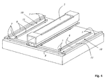
- Fig. 6 shows the thus growing stack 12 of stowed sheets 11. It is clearly seen that the stack has on its outer contour in the lower region of an increasing diameter staircase and in the upper part has a decreasing in diameter staircase. This situation is in Fig. 7 shown in perspective. After the stack 12 is completely made, the stacking table is moved down to expose the finished stack and transported away.
- Fig. 9 shows a detailed view of positioned sheets 11. It can be clearly seen that the sheets 11 are spaced from each other. In particular, one sheet 11 does not serve as a stop for another sheet 11. One of the sheets 11 has a precise notch 13 into which a stop element 7 rounded in its end region engages. There is another stop element 7 arranged on the opposite edge of this sheet, so that the target position of the sheet is completely defined by the stop elements 7.
Landscapes
- Engineering & Computer Science (AREA)
- Mechanical Engineering (AREA)
- Pile Receivers (AREA)
Claims (16)
- Procédé de fabrication d'une pile (12) de tôles (11), en particulier de tôles (11) qui sont dépourvues de trous de guidage et/ou notamment de tôles de transformateur, caractérisé par les étapes suivantes :a. positionnement vertical relatif d'une table d'empilement (6) par rapport à des éléments de butée (7) réglables horizontalement qui sont disposés au-dessus de la table d'empilement (6),b. positionnement horizontal des éléments de butée (7) réglables horizontalement de telle sorte que pour plusieurs tôles (11) à déposer, plusieurs positions de consigne horizontales (10) soient complètement définies dans le même plan horizontal exclusivement à chaque fois par les éléments de butée (7) et de telle sorte que les tôles (11), lorsqu'elles sont déposées, soient guidées latéralement, de préférence exclusivement, par les éléments de butée (7),c. dépose séquentielle ou simultanée des tôles (11) dans les positions de consigne (10) etd. répétition des étapes a à c avec d'autres tôles (11) jusqu'à l'obtention d'une pile souhaitée (12).
- Procédé selon la revendication 1, caractérisé en ce que les éléments de butée (7) sont positionnés de telle sorte que chacune des plusieurs positions de consigne horizontales (10) soit définie sans coïncidence mécanique et/ou en ce que les éléments de butée (7) sont positionnés de telle sorte que chacune des plusieurs positions de consigne horizontales (10) soit définie directement et exclusivement par les éléments de butée (7).
- Procédé selon l'une quelconque des revendications 1 ou 2, caractérisé en ce qu'au moins une tôle (11) à déposer est munie d'un évidement latéral, par exemple d'une encoche latérale (13) et/ou d'un renfoncement, dans laquelle, lequel ou lesquels s'engage au moins en partie un élément de butée (7) pendant la dépose de la tôle (11).
- Procédé selon l'une quelconque des revendications 1 à 3, caractérisé en ce que la pile (12) est formée de couches qui présentent à chaque fois plusieurs tôles (11) disposées les unes à côté des autres et espacées les unes des autres, la distance entre des tôles adjacentes étant inférieure à 0,5 mm, en particulier inférieure à 0,3 mm, notamment étant de l'ordre de 0,1 mm à 0,3 mm, notamment valant environ 0,2 mm.
- Procédé selon l'une quelconque des revendications 1 à 4, caractérisé en ce que la pile (12) est formée de couches décalées les unes par rapport aux autres et/ou en ce que la pile (12) est formée de couches qui présentent à chaque fois des tôles (11) de tailles différentes et/ou en ce que la pile (12) est formée de couches qui présentent à chaque fois des tôles (11) ayant une forme différente.
- Procédé selon l'une quelconque des revendications 1 à 5, caractérisé en ce que le positionnement vertical relatif est réalisé en ce que la table d'empilement (6) est déplacée vers le bas à chaque fois après l'opération de dépose, de préférence suivant une distance qui correspond à l'épaisseur de la tôle (11) préalablement déposée.
- Procédé selon l'une quelconque des revendications 1 à 6, caractérisé en ce que les tôles (11) sont amenées par le haut dans la position de consigne (10) .
- Procédé selon l'une quelconque des revendications 1 à 7, caractérisé en ce que le positionnement relatif et/ou le positionnement et/ou la dépose s'effectuent automatiquement et/ou par commande par ordinateur.
- Procédé selon l'une quelconque des revendications 1 à 8, caractérisé en ce que les tôles (11) à déposer sont découpées et/ou estampées dans un matériau de tôle brut, et en ce que les tôles (11) sont amenées dans leurs positions de consigne (10) directement après le découpage ou l'estampage sans stockage intermédiaire.
- Dispositif de fabrication d'une pile (12) de tôles (11), en particulier de tôles (11) qui sont dépourvues de trous de guidage et/ou notamment de tôles de transformateur, le dispositif présentant une table d'empilement (6) et des éléments de butée (7) réglables horizontalement au-dessus de la table d'empilement (6), lesquels sont réalisés et prévus pour guider latéralement des tôles (11) à déposer, caractérisé en ce que les éléments de butée (7) sont formés et peuvent être positionnés de telle sorte qu'exclusivement les éléments de butée définissent plusieurs positions de consigne horizontales (10) pour plusieurs tôles (11) à déposer dans le même plan horizontal.
- Dispositif selon la revendication 10, caractérisé en ce que les éléments de butée (7) peuvent être positionnés de telle sorte que chacune des plusieurs positions de consigne (10) soit définie sans coïncidence mécanique et/ou en ce que les éléments de butée (7) peuvent être positionnés de telle sorte que chacune des plusieurs positions de consigne horizontales (10) soit définie directement et exclusivement par les éléments de butée (7).
- Dispositif selon l'une quelconque des revendications 10 ou 11, caractérisé en ce qu'au moins un élément de butée (7) présente une saillie qui est réalisée et prévue de manière à s'engager dans un évidement latéral, par exemple une encoche latérale (13) et/ou un renfoncement latéral, d'une tôle (11) à déposer.
- Dispositif selon l'une quelconque des revendications 10 à 12, caractérisé en ce que la table d'empilement (6) est réglable en hauteur et/ou en ce que la table d'empilement (6) peut être réglée en hauteur de telle sorte qu'elle puisse être déplacée vers le bas après la dépose des tôles (11) dans leurs positions de consigne horizontales (10) d'une distance qui correspond à l'épaisseur des tôles (11) déposées.
- Dispositif de traitement (1) comprenant un dispositif selon l'une quelconque des revendications 10 à 13 et un dispositif de coupe et/ou d'estampage (3) pour découper et/ou estamper des tôles (11) à déposer constituées d'un matériau brut.
- Pile de tôles, en particulier de tôles (11) qui sont dépourvues de trous de guidage, fabriquées selon un procédé selon l'une quelconque des revendications 1 à 9 et/ou fabriquées avec un dispositif selon l'une quelconque des revendications 10 à 14, dans laquelle au moins une tôle (11) déposée est pourvue d'un évidement latéral, pour s'engager avec l'élément de butée pendant la dépose de la tôle.
- Pile selon la revendication 15, caractérisée en ce que la pile (12) est formée de couches qui présentent à chaque fois plusieurs tôles (11) disposées les unes à côté des autres et espacées les unes des autres, la distance entre des tôles (11) adjacentes étant inférieure à 0,5 mm, en particulier inférieure à 0,3 mm, notamment étant de l'ordre de 0,1 mm à 0,3 mm, notamment valant environ 0,2 mm.
Applications Claiming Priority (2)
| Application Number | Priority Date | Filing Date | Title |
|---|---|---|---|
| DE201010061022 DE102010061022B3 (de) | 2010-12-03 | 2010-12-03 | Verfahren und Vorrichtung zum Herstellen eines Stapels von Blechen |
| PCT/EP2011/071421 WO2012072699A2 (fr) | 2010-12-03 | 2011-11-30 | Procédé et dispositif de fabrication d'une pile de tôles |
Publications (2)
| Publication Number | Publication Date |
|---|---|
| EP2628165A2 EP2628165A2 (fr) | 2013-08-21 |
| EP2628165B1 true EP2628165B1 (fr) | 2014-06-11 |
Family
ID=45092357
Family Applications (1)
| Application Number | Title | Priority Date | Filing Date |
|---|---|---|---|
| EP11790780.8A Not-in-force EP2628165B1 (fr) | 2010-12-03 | 2011-11-30 | Procédé et dispositif de fabrication d'une pile de tôles |
Country Status (3)
| Country | Link |
|---|---|
| EP (1) | EP2628165B1 (fr) |
| DE (1) | DE102010061022B3 (fr) |
| WO (1) | WO2012072699A2 (fr) |
Families Citing this family (5)
| Publication number | Priority date | Publication date | Assignee | Title |
|---|---|---|---|---|
| ES2891343T3 (es) | 2017-02-21 | 2022-01-27 | Koenig & Bauer Metalprint Gmbh | Procedimiento y dispositivo para el apilado de hojas de material planas, así como máquina de impresión y/o barnizado |
| DE102017202749A1 (de) | 2017-02-21 | 2018-08-23 | Kba-Metalprint Gmbh | Verfahren und Vorrichtung zum Stapeln von flächigen Materialbogen sowie eine Druck- und/oder Lackiermaschine |
| JP2020530655A (ja) * | 2017-08-10 | 2020-10-22 | ハインリヒ ゲオルク ゲーエムベーハー マシーネンファブリークHeinrich Georg GmbH Maschinenfabrik | 変圧器鉄心の製造装置及びその製造方法 |
| CN110394749B (zh) * | 2019-07-30 | 2024-11-01 | 南通思瑞机器制造有限公司 | 变压器硅钢片叠装精定位装置 |
| CN114582619B (zh) * | 2022-03-25 | 2023-11-14 | 无锡普天铁心股份有限公司 | 一种变压器铁心柱预叠装置 |
Family Cites Families (9)
| Publication number | Priority date | Publication date | Assignee | Title |
|---|---|---|---|---|
| DE1081831B (de) * | 1958-08-04 | 1960-05-12 | Moeller & Neumann Gmbh | Einrichtung zum gruppenweise versetzten Stapeln von Blechen |
| DE2163700C3 (de) | 1971-12-22 | 1979-03-15 | Transformatoren Union Ag, 7000 Stuttgart | Verfahren und Vorrichtung zum automatischen Schichten von Einzelblechen für das untere Joch und die Schenkel mehrschenkeliger Kerne für Transformatoren, Drosselspulen u.dgl |
| DE2506681A1 (de) | 1975-02-17 | 1976-08-26 | Heinrich Georg Maschinenfabrik | Stapelvorrichtung fuer transformatorbleche |
| DE2530309C3 (de) * | 1975-07-08 | 1979-01-25 | Waldemar Von 5340 Bad Honnef Lewin | Vorrichtung zur Durchführung eines programmgesteuerten Herstellungsverfahrens von Schichtkernen für Transformatoren |
| DE2537410C2 (de) * | 1975-08-22 | 1983-08-11 | Brown, Boveri & Cie Ag, 6800 Mannheim | Vorrichtung zum Stapeln von Einzelblechen zu einem Blechpaket |
| DE2551497C3 (de) * | 1975-11-17 | 1982-02-11 | Heinrich Georg GmbH Maschinenfabrik, 5910 Kreuztal | Vorrichtung zum kantengleichen Stapeln von Transformatorkernblechen |
| DE3028605C2 (de) | 1980-07-28 | 1983-10-27 | Transformatoren Union Ag, 7000 Stuttgart | Vorrichtung zum Schichten von Kernen für Transformatoren und Drosselspulen |
| JP2903925B2 (ja) | 1992-11-16 | 1999-06-14 | 富士電機株式会社 | 板材の積み重ね装置 |
| DE10332018B3 (de) | 2003-07-15 | 2005-01-13 | Heinrich Georg Gmbh Maschinenfabrik | Vorrichtung zum Halten von abgestapelten Blechen, insbesondere Transformatorblechen |
-
2010
- 2010-12-03 DE DE201010061022 patent/DE102010061022B3/de not_active Withdrawn - After Issue
-
2011
- 2011-11-30 WO PCT/EP2011/071421 patent/WO2012072699A2/fr not_active Ceased
- 2011-11-30 EP EP11790780.8A patent/EP2628165B1/fr not_active Not-in-force
Also Published As
| Publication number | Publication date |
|---|---|
| EP2628165A2 (fr) | 2013-08-21 |
| WO2012072699A3 (fr) | 2012-08-16 |
| WO2012072699A2 (fr) | 2012-06-07 |
| DE102010061022B3 (de) | 2012-03-01 |
Similar Documents
| Publication | Publication Date | Title |
|---|---|---|
| EP3102515B1 (fr) | Procédé et installation de dépôt de barres profilées | |
| DE102012009259B4 (de) | Transformatorenkern-Stapelanlage zum Anschluß an eineTranformatorenblech-Schneid- und Stanzanlage sowieVerfahren zum Betrieb der Transformatorenkern-Stapelanlage | |
| EP2628165B1 (fr) | Procédé et dispositif de fabrication d'une pile de tôles | |
| EP0553724B1 (fr) | Procédé et dispositif pour fabriquer des piles bien déterminées de feuilles pliées ou non-pliées ou d'objets sous forme de feuilles | |
| EP2159173A1 (fr) | Dispositif de transport et procédé de transport ordonné d'articles | |
| DE2151102B2 (de) | Tragwerk und Verfahren zu seiner Herstellung | |
| EP2172109B1 (fr) | Procédé de production de morceaux de pâte pourvus d'une forme au moins essentiellement triangulaire et isocèle à partir d'une bande de pâte et dispositif correspondant | |
| EP2605987B1 (fr) | Dispositif continu | |
| DE3625841A1 (de) | Stapelvorrichtung fuer, insbesondere in einer thermoform-maschine hergestellte, kunststoff-tiefziehteile | |
| DE2254262A1 (de) | Verfahren und vorrichtung zur befestigung von beschlaegen an behaeltern | |
| EP2009652B1 (fr) | Procédé de fabrication de noyaux de transformateur | |
| EP1950159B1 (fr) | Procédé et dispositif de fabrication d'un agencement sous forme d'empilage d'objets plats | |
| DE102014001779A1 (de) | Vorrichtung zum Lagern von Filamentspulen | |
| EP2316611B1 (fr) | Dispositif de chargement de tiges de matière active | |
| DE102009007987A1 (de) | Vorrichtung zum Stapeln von Packungsblechen | |
| DE2744061C2 (fr) | ||
| DE3302046A1 (de) | Verfahren zum stapeln oder entstapeln von langmaterial und stapel- bzw. entstapelvorrichtung | |
| EP0414061B1 (fr) | Dispositif pour retirer une barre métallique d'un faisceau de barres | |
| EP1570962A1 (fr) | Machine et méthode à découper des produits alimentaires | |
| DE2009138C3 (de) | Einrichtung zum kontinuierlichen Abtransport von Werkstücken | |
| AT398746B (de) | Einrichtung zum zusammenstellen von auf einer plattenaufteilanlage durch längs- und querschnitte aus plattenförmigen werkstücken gewonnenen formatzuschnitten zu stapelbildern | |
| DE4209952A1 (de) | Einrichtung bei buntaufteilanlagen | |
| DE19711464C2 (de) | Verfahren zum Stapeln von Transportkisten und Transportkistenstapellager | |
| DE102022117040B4 (de) | Verfahren und Vorrichtung zum Herstellen einer Wellenwicklung mit variablem Drahtabstand | |
| DE2727287A1 (de) | Verfahren und vorrichtung zum biegen profilierter bleche, platten, baender u.dgl. |
Legal Events
| Date | Code | Title | Description |
|---|---|---|---|
| PUAI | Public reference made under article 153(3) epc to a published international application that has entered the european phase |
Free format text: ORIGINAL CODE: 0009012 |
|
| 17P | Request for examination filed |
Effective date: 20130514 |
|
| AK | Designated contracting states |
Kind code of ref document: A2 Designated state(s): AL AT BE BG CH CY CZ DE DK EE ES FI FR GB GR HR HU IE IS IT LI LT LU LV MC MK MT NL NO PL PT RO RS SE SI SK SM TR |
|
| DAX | Request for extension of the european patent (deleted) | ||
| RAP1 | Party data changed (applicant data changed or rights of an application transferred) |
Owner name: HEDRICH GMBH |
|
| GRAP | Despatch of communication of intention to grant a patent |
Free format text: ORIGINAL CODE: EPIDOSNIGR1 |
|
| INTG | Intention to grant announced |
Effective date: 20140107 |
|
| GRAS | Grant fee paid |
Free format text: ORIGINAL CODE: EPIDOSNIGR3 |
|
| GRAA | (expected) grant |
Free format text: ORIGINAL CODE: 0009210 |
|
| AK | Designated contracting states |
Kind code of ref document: B1 Designated state(s): AL AT BE BG CH CY CZ DE DK EE ES FI FR GB GR HR HU IE IS IT LI LT LU LV MC MK MT NL NO PL PT RO RS SE SI SK SM TR |
|
| REG | Reference to a national code |
Ref country code: GB Ref legal event code: FG4D Free format text: NOT ENGLISH |
|
| REG | Reference to a national code |
Ref country code: CH Ref legal event code: EP |
|
| REG | Reference to a national code |
Ref country code: IE Ref legal event code: FG4D Free format text: LANGUAGE OF EP DOCUMENT: GERMAN |
|
| REG | Reference to a national code |
Ref country code: AT Ref legal event code: REF Ref document number: 672598 Country of ref document: AT Kind code of ref document: T Effective date: 20140715 |
|
| REG | Reference to a national code |
Ref country code: DE Ref legal event code: R096 Ref document number: 502011003398 Country of ref document: DE Effective date: 20140724 |
|
| PG25 | Lapsed in a contracting state [announced via postgrant information from national office to epo] |
Ref country code: LT Free format text: LAPSE BECAUSE OF FAILURE TO SUBMIT A TRANSLATION OF THE DESCRIPTION OR TO PAY THE FEE WITHIN THE PRESCRIBED TIME-LIMIT Effective date: 20140611 Ref country code: NO Free format text: LAPSE BECAUSE OF FAILURE TO SUBMIT A TRANSLATION OF THE DESCRIPTION OR TO PAY THE FEE WITHIN THE PRESCRIBED TIME-LIMIT Effective date: 20140911 Ref country code: GR Free format text: LAPSE BECAUSE OF FAILURE TO SUBMIT A TRANSLATION OF THE DESCRIPTION OR TO PAY THE FEE WITHIN THE PRESCRIBED TIME-LIMIT Effective date: 20140912 Ref country code: FI Free format text: LAPSE BECAUSE OF FAILURE TO SUBMIT A TRANSLATION OF THE DESCRIPTION OR TO PAY THE FEE WITHIN THE PRESCRIBED TIME-LIMIT Effective date: 20140611 |
|
| REG | Reference to a national code |
Ref country code: NL Ref legal event code: VDEP Effective date: 20140611 |
|
| REG | Reference to a national code |
Ref country code: LT Ref legal event code: MG4D |
|
| PG25 | Lapsed in a contracting state [announced via postgrant information from national office to epo] |
Ref country code: HR Free format text: LAPSE BECAUSE OF FAILURE TO SUBMIT A TRANSLATION OF THE DESCRIPTION OR TO PAY THE FEE WITHIN THE PRESCRIBED TIME-LIMIT Effective date: 20140611 Ref country code: SE Free format text: LAPSE BECAUSE OF FAILURE TO SUBMIT A TRANSLATION OF THE DESCRIPTION OR TO PAY THE FEE WITHIN THE PRESCRIBED TIME-LIMIT Effective date: 20140611 Ref country code: RS Free format text: LAPSE BECAUSE OF FAILURE TO SUBMIT A TRANSLATION OF THE DESCRIPTION OR TO PAY THE FEE WITHIN THE PRESCRIBED TIME-LIMIT Effective date: 20140611 Ref country code: LV Free format text: LAPSE BECAUSE OF FAILURE TO SUBMIT A TRANSLATION OF THE DESCRIPTION OR TO PAY THE FEE WITHIN THE PRESCRIBED TIME-LIMIT Effective date: 20140611 |
|
| PG25 | Lapsed in a contracting state [announced via postgrant information from national office to epo] |
Ref country code: CZ Free format text: LAPSE BECAUSE OF FAILURE TO SUBMIT A TRANSLATION OF THE DESCRIPTION OR TO PAY THE FEE WITHIN THE PRESCRIBED TIME-LIMIT Effective date: 20140611 Ref country code: EE Free format text: LAPSE BECAUSE OF FAILURE TO SUBMIT A TRANSLATION OF THE DESCRIPTION OR TO PAY THE FEE WITHIN THE PRESCRIBED TIME-LIMIT Effective date: 20140611 Ref country code: PT Free format text: LAPSE BECAUSE OF FAILURE TO SUBMIT A TRANSLATION OF THE DESCRIPTION OR TO PAY THE FEE WITHIN THE PRESCRIBED TIME-LIMIT Effective date: 20141013 Ref country code: SK Free format text: LAPSE BECAUSE OF FAILURE TO SUBMIT A TRANSLATION OF THE DESCRIPTION OR TO PAY THE FEE WITHIN THE PRESCRIBED TIME-LIMIT Effective date: 20140611 Ref country code: RO Free format text: LAPSE BECAUSE OF FAILURE TO SUBMIT A TRANSLATION OF THE DESCRIPTION OR TO PAY THE FEE WITHIN THE PRESCRIBED TIME-LIMIT Effective date: 20140611 Ref country code: ES Free format text: LAPSE BECAUSE OF FAILURE TO SUBMIT A TRANSLATION OF THE DESCRIPTION OR TO PAY THE FEE WITHIN THE PRESCRIBED TIME-LIMIT Effective date: 20140611 |
|
| PG25 | Lapsed in a contracting state [announced via postgrant information from national office to epo] |
Ref country code: PL Free format text: LAPSE BECAUSE OF FAILURE TO SUBMIT A TRANSLATION OF THE DESCRIPTION OR TO PAY THE FEE WITHIN THE PRESCRIBED TIME-LIMIT Effective date: 20140611 Ref country code: IS Free format text: LAPSE BECAUSE OF FAILURE TO SUBMIT A TRANSLATION OF THE DESCRIPTION OR TO PAY THE FEE WITHIN THE PRESCRIBED TIME-LIMIT Effective date: 20141011 Ref country code: NL Free format text: LAPSE BECAUSE OF FAILURE TO SUBMIT A TRANSLATION OF THE DESCRIPTION OR TO PAY THE FEE WITHIN THE PRESCRIBED TIME-LIMIT Effective date: 20140611 |
|
| REG | Reference to a national code |
Ref country code: DE Ref legal event code: R097 Ref document number: 502011003398 Country of ref document: DE |
|
| PLBE | No opposition filed within time limit |
Free format text: ORIGINAL CODE: 0009261 |
|
| STAA | Information on the status of an ep patent application or granted ep patent |
Free format text: STATUS: NO OPPOSITION FILED WITHIN TIME LIMIT |
|
| PG25 | Lapsed in a contracting state [announced via postgrant information from national office to epo] |
Ref country code: DK Free format text: LAPSE BECAUSE OF FAILURE TO SUBMIT A TRANSLATION OF THE DESCRIPTION OR TO PAY THE FEE WITHIN THE PRESCRIBED TIME-LIMIT Effective date: 20140611 |
|
| 26N | No opposition filed |
Effective date: 20150312 |
|
| REG | Reference to a national code |
Ref country code: DE Ref legal event code: R097 Ref document number: 502011003398 Country of ref document: DE Effective date: 20150312 |
|
| PG25 | Lapsed in a contracting state [announced via postgrant information from national office to epo] |
Ref country code: MC Free format text: LAPSE BECAUSE OF FAILURE TO SUBMIT A TRANSLATION OF THE DESCRIPTION OR TO PAY THE FEE WITHIN THE PRESCRIBED TIME-LIMIT Effective date: 20140611 Ref country code: LU Free format text: LAPSE BECAUSE OF FAILURE TO SUBMIT A TRANSLATION OF THE DESCRIPTION OR TO PAY THE FEE WITHIN THE PRESCRIBED TIME-LIMIT Effective date: 20141130 |
|
| PG25 | Lapsed in a contracting state [announced via postgrant information from national office to epo] |
Ref country code: SI Free format text: LAPSE BECAUSE OF FAILURE TO SUBMIT A TRANSLATION OF THE DESCRIPTION OR TO PAY THE FEE WITHIN THE PRESCRIBED TIME-LIMIT Effective date: 20140611 |
|
| REG | Reference to a national code |
Ref country code: IE Ref legal event code: MM4A |
|
| REG | Reference to a national code |
Ref country code: FR Ref legal event code: ST Effective date: 20150731 |
|
| PG25 | Lapsed in a contracting state [announced via postgrant information from national office to epo] |
Ref country code: IE Free format text: LAPSE BECAUSE OF NON-PAYMENT OF DUE FEES Effective date: 20141130 |
|
| PG25 | Lapsed in a contracting state [announced via postgrant information from national office to epo] |
Ref country code: FR Free format text: LAPSE BECAUSE OF NON-PAYMENT OF DUE FEES Effective date: 20141201 |
|
| PGFP | Annual fee paid to national office [announced via postgrant information from national office to epo] |
Ref country code: CH Payment date: 20151118 Year of fee payment: 5 Ref country code: IT Payment date: 20151125 Year of fee payment: 5 Ref country code: DE Payment date: 20151130 Year of fee payment: 5 |
|
| PGFP | Annual fee paid to national office [announced via postgrant information from national office to epo] |
Ref country code: BE Payment date: 20151118 Year of fee payment: 5 |
|
| PG25 | Lapsed in a contracting state [announced via postgrant information from national office to epo] |
Ref country code: SM Free format text: LAPSE BECAUSE OF FAILURE TO SUBMIT A TRANSLATION OF THE DESCRIPTION OR TO PAY THE FEE WITHIN THE PRESCRIBED TIME-LIMIT Effective date: 20140611 |
|
| PG25 | Lapsed in a contracting state [announced via postgrant information from national office to epo] |
Ref country code: BG Free format text: LAPSE BECAUSE OF FAILURE TO SUBMIT A TRANSLATION OF THE DESCRIPTION OR TO PAY THE FEE WITHIN THE PRESCRIBED TIME-LIMIT Effective date: 20140611 Ref country code: CY Free format text: LAPSE BECAUSE OF FAILURE TO SUBMIT A TRANSLATION OF THE DESCRIPTION OR TO PAY THE FEE WITHIN THE PRESCRIBED TIME-LIMIT Effective date: 20140611 |
|
| GBPC | Gb: european patent ceased through non-payment of renewal fee |
Effective date: 20151130 |
|
| PG25 | Lapsed in a contracting state [announced via postgrant information from national office to epo] |
Ref country code: HU Free format text: LAPSE BECAUSE OF FAILURE TO SUBMIT A TRANSLATION OF THE DESCRIPTION OR TO PAY THE FEE WITHIN THE PRESCRIBED TIME-LIMIT; INVALID AB INITIO Effective date: 20111130 Ref country code: TR Free format text: LAPSE BECAUSE OF FAILURE TO SUBMIT A TRANSLATION OF THE DESCRIPTION OR TO PAY THE FEE WITHIN THE PRESCRIBED TIME-LIMIT Effective date: 20140611 Ref country code: MT Free format text: LAPSE BECAUSE OF FAILURE TO SUBMIT A TRANSLATION OF THE DESCRIPTION OR TO PAY THE FEE WITHIN THE PRESCRIBED TIME-LIMIT Effective date: 20140611 |
|
| PG25 | Lapsed in a contracting state [announced via postgrant information from national office to epo] |
Ref country code: GB Free format text: LAPSE BECAUSE OF NON-PAYMENT OF DUE FEES Effective date: 20151130 |
|
| PG25 | Lapsed in a contracting state [announced via postgrant information from national office to epo] |
Ref country code: BE Free format text: LAPSE BECAUSE OF NON-PAYMENT OF DUE FEES Effective date: 20161130 |
|
| REG | Reference to a national code |
Ref country code: DE Ref legal event code: R119 Ref document number: 502011003398 Country of ref document: DE |
|
| REG | Reference to a national code |
Ref country code: CH Ref legal event code: PL |
|
| PG25 | Lapsed in a contracting state [announced via postgrant information from national office to epo] |
Ref country code: CH Free format text: LAPSE BECAUSE OF NON-PAYMENT OF DUE FEES Effective date: 20161130 Ref country code: LI Free format text: LAPSE BECAUSE OF NON-PAYMENT OF DUE FEES Effective date: 20161130 |
|
| PG25 | Lapsed in a contracting state [announced via postgrant information from national office to epo] |
Ref country code: IT Free format text: LAPSE BECAUSE OF NON-PAYMENT OF DUE FEES Effective date: 20161130 |
|
| PG25 | Lapsed in a contracting state [announced via postgrant information from national office to epo] |
Ref country code: DE Free format text: LAPSE BECAUSE OF NON-PAYMENT OF DUE FEES Effective date: 20170601 |
|
| REG | Reference to a national code |
Ref country code: AT Ref legal event code: MM01 Ref document number: 672598 Country of ref document: AT Kind code of ref document: T Effective date: 20161130 |
|
| PG25 | Lapsed in a contracting state [announced via postgrant information from national office to epo] |
Ref country code: AT Free format text: LAPSE BECAUSE OF NON-PAYMENT OF DUE FEES Effective date: 20161130 |
|
| REG | Reference to a national code |
Ref country code: BE Ref legal event code: MM Effective date: 20161130 |
|
| PG25 | Lapsed in a contracting state [announced via postgrant information from national office to epo] |
Ref country code: MK Free format text: LAPSE BECAUSE OF FAILURE TO SUBMIT A TRANSLATION OF THE DESCRIPTION OR TO PAY THE FEE WITHIN THE PRESCRIBED TIME-LIMIT Effective date: 20140611 |
|
| PG25 | Lapsed in a contracting state [announced via postgrant information from national office to epo] |
Ref country code: AL Free format text: LAPSE BECAUSE OF FAILURE TO SUBMIT A TRANSLATION OF THE DESCRIPTION OR TO PAY THE FEE WITHIN THE PRESCRIBED TIME-LIMIT Effective date: 20140611 |