EP2628497B1 - Beatmungs- und Anästhesiesystem - Google Patents
Beatmungs- und Anästhesiesystem Download PDFInfo
- Publication number
- EP2628497B1 EP2628497B1 EP13167921.9A EP13167921A EP2628497B1 EP 2628497 B1 EP2628497 B1 EP 2628497B1 EP 13167921 A EP13167921 A EP 13167921A EP 2628497 B1 EP2628497 B1 EP 2628497B1
- Authority
- EP
- European Patent Office
- Prior art keywords
- measuring module
- unit
- main unit
- ventilation
- patient
- Prior art date
- Legal status (The legal status is an assumption and is not a legal conclusion. Google has not performed a legal analysis and makes no representation as to the accuracy of the status listed.)
- Active
Links
Images



Classifications
-
- A—HUMAN NECESSITIES
- A61—MEDICAL OR VETERINARY SCIENCE; HYGIENE
- A61M—DEVICES FOR INTRODUCING MEDIA INTO, OR ONTO, THE BODY; DEVICES FOR TRANSDUCING BODY MEDIA OR FOR TAKING MEDIA FROM THE BODY; DEVICES FOR PRODUCING OR ENDING SLEEP OR STUPOR
- A61M16/00—Devices for influencing the respiratory system of patients by gas treatment, e.g. ventilators; Tracheal tubes
- A61M16/01—Devices for influencing the respiratory system of patients by gas treatment, e.g. ventilators; Tracheal tubes specially adapted for anaesthetising
-
- A—HUMAN NECESSITIES
- A61—MEDICAL OR VETERINARY SCIENCE; HYGIENE
- A61M—DEVICES FOR INTRODUCING MEDIA INTO, OR ONTO, THE BODY; DEVICES FOR TRANSDUCING BODY MEDIA OR FOR TAKING MEDIA FROM THE BODY; DEVICES FOR PRODUCING OR ENDING SLEEP OR STUPOR
- A61M16/00—Devices for influencing the respiratory system of patients by gas treatment, e.g. ventilators; Tracheal tubes
- A61M16/10—Preparation of respiratory gases or vapours
- A61M16/12—Preparation of respiratory gases or vapours by mixing different gases
- A61M16/122—Preparation of respiratory gases or vapours by mixing different gases with dilution
-
- A—HUMAN NECESSITIES
- A61—MEDICAL OR VETERINARY SCIENCE; HYGIENE
- A61M—DEVICES FOR INTRODUCING MEDIA INTO, OR ONTO, THE BODY; DEVICES FOR TRANSDUCING BODY MEDIA OR FOR TAKING MEDIA FROM THE BODY; DEVICES FOR PRODUCING OR ENDING SLEEP OR STUPOR
- A61M16/00—Devices for influencing the respiratory system of patients by gas treatment, e.g. ventilators; Tracheal tubes
- A61M16/10—Preparation of respiratory gases or vapours
- A61M16/14—Preparation of respiratory gases or vapours by mixing different fluids, one of them being in a liquid phase
- A61M16/18—Vaporising devices for anaesthetic preparations
-
- A—HUMAN NECESSITIES
- A61—MEDICAL OR VETERINARY SCIENCE; HYGIENE
- A61M—DEVICES FOR INTRODUCING MEDIA INTO, OR ONTO, THE BODY; DEVICES FOR TRANSDUCING BODY MEDIA OR FOR TAKING MEDIA FROM THE BODY; DEVICES FOR PRODUCING OR ENDING SLEEP OR STUPOR
- A61M16/00—Devices for influencing the respiratory system of patients by gas treatment, e.g. ventilators; Tracheal tubes
- A61M16/22—Carbon dioxide-absorbing devices ; Other means for removing carbon dioxide
-
- A—HUMAN NECESSITIES
- A61—MEDICAL OR VETERINARY SCIENCE; HYGIENE
- A61M—DEVICES FOR INTRODUCING MEDIA INTO, OR ONTO, THE BODY; DEVICES FOR TRANSDUCING BODY MEDIA OR FOR TAKING MEDIA FROM THE BODY; DEVICES FOR PRODUCING OR ENDING SLEEP OR STUPOR
- A61M2205/00—General characteristics of the apparatus
- A61M2205/35—Communication
- A61M2205/3546—Range
- A61M2205/3561—Range local, e.g. within room or hospital
-
- A—HUMAN NECESSITIES
- A61—MEDICAL OR VETERINARY SCIENCE; HYGIENE
- A61M—DEVICES FOR INTRODUCING MEDIA INTO, OR ONTO, THE BODY; DEVICES FOR TRANSDUCING BODY MEDIA OR FOR TAKING MEDIA FROM THE BODY; DEVICES FOR PRODUCING OR ENDING SLEEP OR STUPOR
- A61M2205/00—General characteristics of the apparatus
- A61M2205/82—Internal energy supply devices
- A61M2205/8206—Internal energy supply devices battery-operated
-
- A—HUMAN NECESSITIES
- A61—MEDICAL OR VETERINARY SCIENCE; HYGIENE
- A61M—DEVICES FOR INTRODUCING MEDIA INTO, OR ONTO, THE BODY; DEVICES FOR TRANSDUCING BODY MEDIA OR FOR TAKING MEDIA FROM THE BODY; DEVICES FOR PRODUCING OR ENDING SLEEP OR STUPOR
- A61M2230/00—Measuring parameters of the user
- A61M2230/60—Muscle strain, i.e. measured on the user
-
- A—HUMAN NECESSITIES
- A61—MEDICAL OR VETERINARY SCIENCE; HYGIENE
- A61M—DEVICES FOR INTRODUCING MEDIA INTO, OR ONTO, THE BODY; DEVICES FOR TRANSDUCING BODY MEDIA OR FOR TAKING MEDIA FROM THE BODY; DEVICES FOR PRODUCING OR ENDING SLEEP OR STUPOR
- A61M2230/00—Measuring parameters of the user
- A61M2230/63—Motion, e.g. physical activity
-
- H—ELECTRICITY
- H02—GENERATION; CONVERSION OR DISTRIBUTION OF ELECTRIC POWER
- H02J—ELECTRIC POWER NETWORKS; CIRCUIT ARRANGEMENTS OR SYSTEMS FOR SUPPLYING OR DISTRIBUTING ELECTRIC POWER; SYSTEMS FOR STORING ELECTRIC ENERGY
- H02J2105/00—Networks for supplying or distributing electric power characterised by their spatial reach or by the load
- H02J2105/40—Networks for supplying or distributing electric power characterised by their spatial reach or by the load characterised by the loads connecting to the networks or being supplied by the networks
- H02J2105/46—Medical devices, medical implants or life supporting devices
-
- H—ELECTRICITY
- H02—GENERATION; CONVERSION OR DISTRIBUTION OF ELECTRIC POWER
- H02J—ELECTRIC POWER NETWORKS; CIRCUIT ARRANGEMENTS OR SYSTEMS FOR SUPPLYING OR DISTRIBUTING ELECTRIC POWER; SYSTEMS FOR STORING ELECTRIC ENERGY
- H02J7/00—Circuit arrangements for charging or discharging batteries or for supplying loads from batteries
- H02J7/50—Circuit arrangements for charging or discharging batteries or for supplying loads from batteries acting upon multiple batteries simultaneously or sequentially
-
- H—ELECTRICITY
- H02—GENERATION; CONVERSION OR DISTRIBUTION OF ELECTRIC POWER
- H02J—ELECTRIC POWER NETWORKS; CIRCUIT ARRANGEMENTS OR SYSTEMS FOR SUPPLYING OR DISTRIBUTING ELECTRIC POWER; SYSTEMS FOR STORING ELECTRIC ENERGY
- H02J7/00—Circuit arrangements for charging or discharging batteries or for supplying loads from batteries
- H02J7/865—Battery or charger load switching, e.g. concurrent charging and load supply
Definitions
- the present invention relates to a respiratory or anesthetic system according to the preamble of claim 1.
- Ventilators or respiratory systems are used to ventilate patients and can also be used with an anesthetic refractor and anesthetic dispensers as anesthetic or anesthetic systems for anesthesia.
- the exhaled expiratory gas exhaled by the patient may be reused as inspiratory gas, i. H. It is a rebreathing system with a breathing air circulation system.
- a gas delivery means is provided which directs the breathing air to the patient during inspiration.
- the gas conveyor is either switched off or is operated only with a very low flow.
- the ventilation performed by the ventilator or anesthesia system can either completely take over the self-ventilatory activity of the patient or, in a supporting procedure, only partially replace the patient's own respiratory activity so that the respiratory muscles of the patient take over part of the respiratory activity.
- control of the proportion of ventilation is required, ie, the proportion of self-ventilatory activity of the patient can be controlled and / or regulated.
- the performance of the gas delivery unit of the ventilation or anesthesia system to control and adjust the timing and the amplitude of ventilation with respect to the patient's own breath.
- EMG sensors electromyographic sensors Invasively recorded the electromyographic activity of the patient's respiratory muscles.
- the EMG sensors are invasive, especially in a trachea, placed on the patient.
- the DE 10 2007 062 214 B3 shows a method for automatically controlling a ventilation system for proportional assist ventilation with a control device and a fan that supplies a breathing gas with a predetermined pressure from the control unit.
- An electromyographic electrical signal is recorded with electrodes and from this the respiratory activity and the respiratory muscle pressure are determined.
- WO 2006/131149 A1 discloses a ventilator or anesthesia system for ventilating a patient, comprising a gas delivery device, at least one gas line for forming a breathing air duct system, at least one EMG sensor suitable for non-invasive detection of the electromyographic muscle activity of the respiratory muscles of a patient to be ventilated on the skin surface, a control device for Control and / or regulation of the gas delivery device as a function of the detected muscle activity of the respiratory muscles, a main unit which has the gas delivery device, and at least one measurement module to which the at least one EMG sensor is arranged.
- the document US 2007 / 163588A1 discloses a ventilator having as a power supply a battery with an integrated charger.
- two power supply units can be provided in corresponding receiving devices in a main unit.
- Both a rechargeable battery and a rechargeable battery pack are provided. These rechargeable batteries can be charged by a charger.
- the charger can be permanently connected to these energy storage devices and provided for this purpose in a receiving device of the main unit.
- the object of the present invention is therefore to provide a ventilation or anesthesia system and a method for controlling and / or regulating a ventilation or anesthetic system in which an adaptation of the proportion of ventilation to the performance of the respiratory muscles of the ventilated patient without an invasive measurement of the electromyographic activity of the respiratory muscles is possible.
- a ventilation or anesthesia system for ventilating a patient, comprising a gas delivery device, at least one gas line for forming a breathing air system, in particular a Atemluft Vietnamesesystems, at least one EMG sensor (electromyographic sensor) for non-invasive detection of electromyographic muscle activity of the respiratory muscles a patient to be ventilated at the skin surface, a control device for controlling and / or regulating the power of the gas delivery device in dependence on the detected muscle activity of the respiratory muscles, a main unit having a main housing and the gas delivery device, at least one measurement module to which the at least one EMG sensor is arranged, wherein the at least one measurement module is a separate unit from the main unit, characterized in that the main unit comprises a charge and switch unit, wherein in the charging and switching unit batteries are charged by means of charge parts, that the charging and switching unit again comprises switching units which are adapted to connect only a first battery to the measuring module for powering the measuring module, further at least one other battery with only one Charging part for charging the
- the sEMG sensor is thus a surface EMG sensor and records the electrical activity of the respiratory muscles non-invasively, ie on the surface, in particular skin surface, of the patient.
- an unpleasant or harmful to the patient invasive measurement of the electrical activity of the respiratory muscles for example in the trachea invasive with an EMG sensor, is no longer required.
- the beginning of the respiratory phase of the patient and / or the intrinsic activity or self-breathing of the patient can thus be detected non-invasively with the at least one sEMG sensor.
- the ventilation or anesthesia system with a device for. B. at least one key and / or a lever for controlling and / or regulating and / or changing the proportion of ventilation provided.
- a physician can thus increase the proportion of ventilation and reduce and thereby adapt to the health of the patient, for example, for a slow weaning of the patient from the ventilation.
- An increase in ventilation causes a reduction in the patient's own breathing and vice versa.
- the respiration or anesthesia system preferably comprises at least two sEMG sensors, in particular at least one pair of sEMG sensors.
- the at least one sEMG sensor is arranged at a distance of less than 100 cm, 70 cm, 50 cm, 30 cm, 20 cm or 10 cm from the measuring module.
- the at least one sEMG sensor is connected to the at least one measuring module with an analog cable or with a radio link.
- the tension from the respiratory muscle activity measured by the at least one sEMG sensor preferably at the skin surface, is conducted to the at least one measuring module with the analogue cable.
- very small voltages in the range of a few to about 100 ⁇ V are measured by the at least one sEMG sensor.
- the measured voltage can be converted into digital signals and transmitted to the measuring module and / or the main unit.
- the at least one measuring module is provided with an analog-digital conversion unit for converting the analogous electromyographic muscle activity detected by the at least one sEMG sensor into digital signals.
- the at least one sEMG sensor detects only very small voltages from the respiratory muscles, so that when these very small currents are conducted over a greater distance to the main unit, these very small voltages can be falsified. For this reason, conversion of these very small measured voltages into digital signals makes sense and is effective in locally near conversion in the analog-to-digital conversion unit in the at least one measurement module.
- the at least one measuring module expediently has a data processing unit and / or a power supply unit.
- the energy supply unit is at least one battery, preferably a plurality of batteries, and / or a capacitor, preferably a plurality of capacitors, as energy storage.
- the main unit is provided with a charge unit for the at least one energy store.
- the power supply unit in the at least one measurement module is at least one power cable and the at least one power cable is routed to the main unit for conducting electrical power from the main unit to the at least one measurement module and preferably at least one of the at least one Power cable conducted electricity with an induction unit with two coils by induction from the main unit to the at least one power cable conductive.
- the current is inducted in the induction unit from a primary coil transmit a secondary coil and thus the measuring module is electrically and / or magnetically decoupled from the main unit.
- the induction unit is arranged in or on the main unit.
- the respiration or anesthesia system is provided with at least two energy stores, in particular a battery or a capacitor, and a charging and switching unit for energy supply of the at least one measuring module, so that during a discharge at least one energy storage of at least one energy storage of a power supply of the main unit electrically is separated and electrically connected to the measuring module and during a charging phase of the at least one energy storage, the at least one energy storage is electrically separated from the at least one measuring module and is electrically connected to the main unit.
- the at least one measuring module of the main unit is electrically and / or magnetically decoupled, because the at least one measuring module is not connected simultaneously with an electrical cable directly to the main unit.
- the at least one measuring module with at least one MMG sensor (mechanomyographic sensor) and / or at least one acceleration sensor and / or a microphone for non-invasive detection of the muscle activity of the respiratory muscles, so that these sensors are non-invasive sensors.
- the at least one MMG sensor (mechanomyographischer sensor) and / or the at least one acceleration sensor and / or the microphone is connected in an analogous manner as the at least one sEMG sensor with an analog cable to the measuring module.
- control device determines the power of the gas delivery device and / or the pressure of the inspiration gas as a function of the data and / or currents of the at least one MMG sensor and / or the at least one acceleration sensor and / or the microphone can be controlled and / or regulated.
- Method according to the invention for controlling and / or regulating a respiratory or anesthetic system, in particular a respiratory or anesthesia system described in this patent application comprising the steps of: conveying respiratory air through at least one gas line of a respiratory air duct system with a gas conveyor, detecting the electromyographic muscular activity of the respiratory musculature ventilating patients preferably with an EMG sensor, controlling and / or regulating the performance of the gas delivery device and / or the pressure of the inspiratory air in response to the detected muscle activity of the respiratory muscles, wherein the electromyographic muscle activity of at least one sEMG sensor on a skin surface of the respiratory Patient is detected.
- the analogous electromyographic muscle activity detected by the at least one sEMG sensor is converted into digital signals by means of an analog-to-digital conversion unit.
- the sEMG sensor detects as analogous muscle activity a very small tension of the respiratory muscle.
- At least one measuring module with the at least one sEMG sensor with electrical energy from a main unit of the respiratory or anesthetic machine.
- the electrical energy is passed through at least one power cable from the main unit to the at least one measuring module and thereby, preferably at the main unit, the current is transmitted with induction to reduce the coupling capacitance between the at least one measuring module and the main unit (at least a measuring module is thus electrically and / or magnetically decoupled from the main unit because a power line to the main unit to the at least one measuring module is possible only by induction) and / or at least one measuring module at least one energy storage is arranged and after the Detecting the electromyographic muscle activity with the at least one measuring module on the patient, the at least one measuring module is brought to the main unit and at the main unit of at least one energy storage is charged and preferably at least one other measuring module after charging the at least one energy storage at the main unit that at least another measuring module brought to the patient for detecting the electromyographic muscle activity (the at least one measuring module is thus electrically and / or magnetically decoupled from the main unit, because the energy storage is only charged when the energy storage is not
- the digital data for the muscle activity of the respiratory muscles are transmitted wirelessly (with a radio link) or wired from the at least one measurement module to the main unit.
- a coupling capacity between the at least one measuring module and the main unit is less than 40 to 50 pF, preferably less than 30 to 40 pF, in particular less than 10 to 12 pF (pFarad).
- the main unit of the ventilation or anesthesia system has a CO 2 absorber.
- the CO 2 absorber removes the carbon dioxide from the expiratory gas exhaled by the patient to be ventilated.
- the official or anesthesia system includes an inspiratory tube and an expiratory tube.
- the ventilation or anesthesia system has a Y-piece or a breathing mask.
- the inspiratory and / or expiratory tube are connected to the Y-piece or the breathing mask.
- a check valve are arranged on the inspiratory and expiratory tube.
- the main unit of the respiratory or anesthesia system comprises an anesthetic reflector.
- anesthetic reflector By means of the Anallehesiestoffreflektors the anesthetic, z. B. halotan or enflurane, the expired gas withdrawn and then fed the extracted anesthetic the inspiratory gas.
- the main unit of the ventilator or anesthesia system comprises an anesthetic dispenser with an anesthetic reservoir.
- Anesthetic agent is added to the inspiration gas by means of the anesthetic agent meter.
- the anesthetic agent is generally in a liquid form and the anesthetic agent is converted in the anesthetic dispenser from the liquid to the gaseous phase and thus supplied to the patient.
- the expiratory gas exhaled by the patient is at least partially returned to the patient as inspiratory gas.
- the exhaled expiratory gas is preferably in the CO 2 absorber, the carbon dioxide withdrawn and preferably in a gas mixer enriches the inspiratory gas to be supplied to the patient with a mixture of oxygen, nitrous oxide, air and / or xenon.
- Respirators or respiratory systems 1 are used to ventilate patients 20 and anesthesia devices or anesthesia systems 1 are used in addition to the ventilation for anesthesia of patients 20.
- the respiratory or Anesthesia system 1 in this case has a breathing air circulation system, that is to say that the exhaled expiratory gas exhaled by the patient 20 is reused for inspiration as inspiratory gas.
- the breathing air is guided by a gas delivery device 3 as a fan in a main unit 2 through gas lines 4 in a breathing air circulation system.
- the gas lines 4 are thus connected to the main unit 2.
- a first, inspiratory check valve and a second expiratory check valve are arranged.
- an expiratory gas line or an expiratory tube 8 and an inspiratory gas line or an inspiratory tube 7 are formed.
- a Y-piece is connected, which leads the inspiratory and expiratory gas to and from a patient 20 to be ventilated by means of a patient connection piece.
- An unillustrated CO 2 absorber in the main unit 2 absorbs the carbon dioxide contained in the expiratory gas.
- an anesthetic agent reflector (not shown) in the main unit 2 and an anesthetic dispenser, the inspiratory gas is enriched with anesthetic (not shown).
- a mixture of oxygen and nitrous oxide is supplied to the inspiration gas by means of a gas mixer, not shown in the main unit.
- the gas mixer is supplied separately by means of two valves, the oxygen and nitrous oxide.
- the respiratory or anesthesia system 1 further comprises a measuring module 5 with two sEMG sensors 6, wherein the sEMG sensors 6 are electrically connected to a measuring module 5 with an analog cable of short length, for example in the range between 3 and 15 cm.
- the two sEMG sensors 6 rest in the chest region on the skin of the patient 20, ie the sEMG sensors 6 measure the electrical activity of the respiratory muscles non-invasively.
- the measuring module 5 has connectors, not shown, for connecting up to five pairs of sEMG sensors 6 (not shown).
- an analog-to-digital conversion unit 10 and a data processing unit 11 is ordered.
- the sEMG sensors 6 measure very small currents with a voltage of between a few to about 100 ⁇ V, so that when these small currents are conducted over a greater distance through a long analog cable, a falsification of them small measured voltages can occur. For this reason, with the analog-to-digital conversion unit 10, the voltages detected by the two sEMG sensors 6 are converted into digital signals at a short distance from the sEMG sensors 6.
- the measuring module 5 is supplied with electrical power from the main unit 2 by two power cables 15 (only one power cable 15 shown).
- the power cables 15 in the measuring module 5 thus represent a power supply unit (not shown).
- a DC-DC converter 17 is arranged as an induction unit 19 with a primary and secondary coil, not shown.
- DC is first modulated, then transmitted the modulated DC by induction from the primary to the secondary coil and then the current induced in the secondary coil again converted into DC and passed through the two power cables 15 to the measuring module 2 for power supply of the measuring module 2.
- the power supply of the measuring module 2 is electrically or magnetically decoupled from the main unit 2, so that disturbances in the conversion of the measured analog currents into digital signals in the analog-to-digital conversion unit 10 are very low.
- the measuring module 5 is connected to the main unit 2 by a data cable 16 for transmitting the digital data generated by the analog-to-digital conversion unit 10 to the main unit 2.
- the data cable 16 is connected to an electrical isolation unit 18 in the main unit 2 and by the potential separation unit 18, the digital data is transmitted to a controller 9 in the main unit 2.
- the data cable 16 may be an electrical cable for conducting power or a fiber optic cable for optically transmitting data.
- the potential separation unit 18 the electrical potential of the measuring module 5 is separated from the electrical potential of the main unit 2, so that even with different electrical potentials in the main unit 2 and the measuring module 5 through the data cable 16 no resulting current flows.
- the digital signals are evaluated and controlled as a function of the digital signals, ie the measured from the two sEMG sensors 6 on the skin surface electrical potential difference from the respiratory muscle activity, the performance of the gas conveyor 3 and / or regulated.
- digital signals can be stored and processed and further, a measurement module 5 and thus a patient 20 can be identified by the control unit 9 when using multiple measurement modules 5 for the same main unit 2.
- the data processing unit 11 checksums the transmitted digital data and / or control signals are transmitted to the control device 9 in order to detect possible errors in the transmission from the measuring module 5 to the main unit 2 and the control device 9, respectively. This is to prevent false ventilation of the patient 20 due to data transmission errors.
- the measuring module 5 also has at least one sensor (not shown) for detecting a patient's ground, i. H. the average electrical potential of the patient 20, on. Notwithstanding this, the patient's ground can also be calculated from the average electrical potential detected by the sEMG sensors 6.
- This sensor is a non-invasive sensor that measures the electrical potential at the skin surface.
- the electrical potential in the measuring module 5 is controlled by the data processing unit 11 in such a way that the electrical potential in the measuring module 5 essentially corresponds to the patient's ground, in order to prevent resulting currents in the analog cable for connecting the sEMG sensors 6 to the measuring module 5.
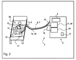
- Fig. 2 a second embodiment of the respiratory or anesthesia system 1 is shown.
- the power cable 15 and the data cable 16 for connecting the measuring module 5 to the main unit 2 is integrated into the inspiratory tube 7 and / or the expiratory tube 8, so that the main unit 2 and the measuring module 5 are connected to one another only by a line unit or a cable channel for pneumatic as well as electrical connection.
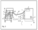
- a third embodiment of the respiratory or anesthesia system 1 is shown.
- a battery 13 is installed as an energy storage 12 and is used for electrical power supply of the measuring module 5.
- a transmitter 21 and in the main unit 2 a receiver 22 installed for wireless transmission of digital signals from the measuring module 5 From the receiver 22, the digital signals with respect to the electromyographic respiratory muscle activity are transmitted to the control device 9.
- a measuring module 5 can be identified by the control device 9 with a bidirectional radio link.
- the respiration or anesthesia system 1 comprises two or three measurement modules 5, because a measurement module 5 is located at the patient 5 for the detection of the electromyographic respiratory muscle activity and transmission of the digital data, so that the battery 13 in the measurement module 5 on the patient 5 is discharged.
- the second or third measuring module 5 is arranged in a loading unit 14 as a parking holder 23 and is charged.
- the measuring module 5 on the patient 20 is replaced by a charge module 14 charged in the charging unit 14 when falling below a predetermined state of charge of the battery 13.
- the measuring module 5 is provided with a central plug-in unit, not shown, with which all sEMG sensors 6 arranged on the patient 20 can be connected to the measuring module 5.
- the charging time of a measuring module 5 in the parking holder 23 is a maximum of half the operating time of the measuring module 5 on the patient. Expediently, the charging time is 1/4 or 1/6 of the operating time. An operating time of 24 h is z. B. compared to a charging time of 4 h.
- the measuring module 5 can from the Control means 9 are also identified by means of data in the data processing unit 11.
- Fig. 4 and 5 show two embodiments of the cargo unit 14.
- the energy or current transmission takes place from a transmitter coil 24 on the main unit 2 by means of electrical induction contactlessly to a slave coil 25 in the measuring module 5.
- the second embodiment ( Fig. 5 ) of the charge unit 14 shows a contact-bound current transfer from the main unit 2 with a designed as a metal spring 27 Kunststoffelemerit 26 on the main unit 2 and a metal plate 29 as a mating contact element 28.
- the charge unit 2 has two contact elements 26 and the measuring module 5 is two Counter contact elements 28 provided.
- electric power can be conducted from the main unit 2 into the battery 13.
- a fourth embodiment of the ventilation or anesthesia system 1 is shown.
- a charging and switching unit 30 is arranged in the charging and switching unit 30 in the charging and switching unit 30 batteries 13 are charged with charge parts 31.
- the charge parts 31 are connected to charge cables 33 to the main unit 2 and the batteries 13.
- the power cables 15 are led to the batteries 13, with which the current is conducted from the batteries 13 in the measuring module 5.
- Switching units 32 on the batteries 13 are used so that only one battery 13 is connected to the measuring module 5 for powering the measuring module 5 with the one battery 13 and at least one other battery 13 is connected to only one charge part 31 for charging the at least one other battery 13.
- the discharged battery 13 with the switching unit 32 is electrically disconnected from the measuring module 5 and another charged battery 13 is electrically connected to the measuring module 5.
- the discharged battery 13 is then electrically connected to the charging member 31 and charged.
- the batteries 13 are thus never connected to the measuring module 5 as well as to the charging part 31 or the main unit 2 in a timely manner, so that the measuring module 5 electrically or magnetically decoupled from the main unit 2.
- the charging and switching unit 30 may also be arranged in the measuring module 5 instead of in the main unit 2 (not shown).
- the gas delivery device 3 is operated as a function of the electromyographic respiratory muscle activity, which is measured with sEMG sensors 6, so that a disadvantageous invasive measurement is no longer necessary.
- the power supply of the measuring module 5 is electrically and magnetically decoupled from the main unit 2, so that no disturbances due to an electrical and magnetic coupling of the measuring module 5 with the main unit 2 occur.
Landscapes
- Health & Medical Sciences (AREA)
- Anesthesiology (AREA)
- Emergency Medicine (AREA)
- Pulmonology (AREA)
- Engineering & Computer Science (AREA)
- Biomedical Technology (AREA)
- Heart & Thoracic Surgery (AREA)
- Hematology (AREA)
- Life Sciences & Earth Sciences (AREA)
- Animal Behavior & Ethology (AREA)
- General Health & Medical Sciences (AREA)
- Public Health (AREA)
- Veterinary Medicine (AREA)
- Measurement Of The Respiration, Hearing Ability, Form, And Blood Characteristics Of Living Organisms (AREA)
Description
- Die vorliegende Erfindung betrifft eine Beatmungs- oder Anästhesiesystem gemäß dem Oberbegriff des Anspruches 1.
- Für verschiedene medizinische Anwendungen, z. B. bei Operationen, ist eine Beatmung von Patienten notwendig. Beatmungsgeräte bzw. Beatmungssysteme dienen zur Beatmung von Patienten und können zusätzlichen mit einem Anästhesiemittelreflektor und Anästhesiemitteldosierer als Anästhesiegeräte bzw. Anästhesiesysteme auch zur Narkose eingesetzt werden. Bei einigen Beatmungs-oder Anästhesiesystemen kann wenigstens teilweise das von dem Patienten ausgeatmete Exspirationsgas wieder als Inspirationsgas wiederverwendet werden, d. h. es handelt sich um ein Rückatemsystem mit einem Atemluftkreissystem. In dem Beatmungsgerät mit dem Atemluftkreissystem ist eine Gasfördereinrichtung vorhanden, welche die Atemluft während der Inspiration zum Patienten leitet. Während und nach der Ausatmung ist die Gasfördereinrichtung entweder abgeschaltet oder wird nur mit einem sehr geringen Förderstrom betrieben.
- Die von dem Beatmungs- oder Anästhesiesystem durchgeführte Beatmung kann entweder vollständig die Eigenbeatmungstätigkeit des Patienten übernehmen oder bei einem unterstützenden Verfahren die eigenen Atemtätigkeit des Patienten lediglich nur teilweise ersetzten, so dass die Atemmuskulatur des Patienten einen Teil der Atemtätigkeit übernimmt. Für eine verbesserte Therapie, insbesondere bei COPD-Patienten, ist eine Steuerung des Anteils der Beatmung erforderlich, d. h. der Anteil der Eigenbeatmungstätigkeit des Patienten kann gesteuert und/oder geregelt werden. Hierzu sind die Leistung der Gasfördereinheit des Beatmungs- oder Anästhesiesystems zu steuern und der Zeitpunkt und die Amplitude der Beatmung in Bezug auf die der Eigenatmung des Patienten anzupassen. Dazu wird mit elektromyographischen Sensoren (EMG-Sensoren) invasiv die elektromyographische Aktivität der Atemmuskulatur des Patienten erfasst. Die EMG-Sensoren sind invasiv, insbesondere in einer Luftröhre, am Patienten angeordnet.
- Die
DE 10 2007 062 214 B3 zeigt ein Verfahren zum automatischen Steuern eines Beatmungssystems für proportional unterstützende Ventilation mit einer Steuereinrichtung und einem Ventilator, der ein Atemgas mit einem von der Steuereinheit vorgegebenen Druck liefert. Mit Elektroden wird elektromyographisch ein elektrisches Signal aufgenommen und hieraus die Atemaktivität und der Atemmuskeldruck bestimmt. - Das Dokument
WO 2006/131149 A1 offenbart ein Beatmungs- oder Anästhesiesystem zur Beatmung eines Patienten, umfassend eine Gasfördereinrichtung, wenigstens eine Gasleitung zur Ausbildung eines Atemluftleitungssystems, wenigstens ein EMG-Sensor geeignet zur nicht-invasiven Erfassung der elektromyografischen Muskelaktivität der Atemmuskulatur eines zu beatmenden Patienten an dessen Hautoberfläche, eine Steuereinrichtung zur Steuerung und/oder Regelung der Gasfördereinrichtung in Abhängigkeit von der erfassten Muskelaktivität der Atemmuskulatur, eine Haupteinheit, welche die Gasfördereinrichtung aufweist, und wenigstens ein Messmodul, an welchem der wenigstens eine EMG-Sensor angeordnet ist. - Das Dokument
US 2007/163588A1 offenbart ein Beatmungsgerät, welches als Stromversorgung eine Batterie mit einem integrierten Ladegerät aufweist. Hierbei können zwei Energieversorgungseinheiten in entsprechenden Aufnahmevorrichtungen in einer Haupteinheit vorgesehen werden. Sowohl eine wiederaufladbare Batterie als auch eine wiederaufladbare Batteriepackung sind vorgesehen. Diese wiederaufladbaren Batterien können durch ein Ladegerät aufgeladen werden. Das Ladegerät kann permanent mit diesen Energiespeichern verbunden und hierzu in einer Aufnahmevorrichtung der Haupteinheit vorgesehen sein. - Die Aufgabe der vorliegenden Erfindung besteht deshalb darin, ein Beatmungs- oder Anästhesiesystem und ein Verfahren zur Steuerung und/oder Regelung eines Beatmungs- oder Anästhesiesystems zur Verfügung zu stellen, bei dem eine Anpassung des Anteils der Beatmung an die Leistungsfähigkeit der Atemmuskulatur des beatmeten Patienten ohne eine invasive Messung der elektromyographischen Aktivität der Atemmuskulatur möglich ist.
- Diese Aufgabe wird gelöst mit einem Beatmungs- oder Anästhesiesystem zur Beatmung eines Patienten, umfassend eine Gasfördereinrichtung, wenigstens eine Gasleitung zur Ausbildung eines Atemluftleitungssystems, insbesondere eines Atemluftkreissystems, wenigstens einen EMG-Sensor (elektromyographischer Sensor) zur nicht-invasiven Erfassung der elektromyographischen Muskelaktivität der Atemmuskulatur eines zu beatmenden Patienten an dessen Hautoberfläche, eine Steuereinrichtung zur Steuerung und/oder Regelung der Leistung der Gasfördereinrichtung in Abhängigkeit von der erfassten Muskelaktivität der Atemmuskulatur, eine Haupteinheit mit einem Hauptgehäuse und der Gasfördereinrichtung, wenigstens ein Messmodul, an welchem der wenigstens eine EMG-Sensor angeordnet ist, wobei das wenigstens eine Messmodul eine von der Haupteinheit getrennte Baueinheit ist, dadurch gekennzeichnet, dass die Haupteinheit eine Ladungs- und Schalteinheit umfasst, wobei in der Ladungs- und Schalteinheit Batterien mittels Ladungsteilen aufgeladen werden, dass die Ladungs- und Schalteinheit wiederum Schalteinheiten umfasst, welche dazu ausgebildet sind, nur eine erste Batterie mit dem Messmodul zur Stromversorgung des Messmoduls zu verbinden, ferner wenigstens eine andere Batterie nur mit einem Ladungsteil zum Aufladen der anderen Batterie zu verbinden, und ferner die erste Batterie nach dem Entladen von dem Messmodul elektrisch zu trennen und die andere, aufgeladene Batterie mit dem Messmodul elektrisch zu verbinden, wobei der wenigstens eine EMG-Sensor ein sEMG-Sensor ist. Der sEMG-Sensor ist damit ein surface EMG-Sensor und erfasst die elektrische Aktivität der Atemmuskulatur nicht-invasiv, d. h. an der Oberfläche, insbesondere Hautoberfläche, des Patienten. Damit ist in vorteilhafter Weise eine für den Patienten unangenehme oder schädliche invasive Messung der elektrischen Aktivität der Atemmuskulatur, beispielsweise in der Luftröhre invasiv mit einem EMG-Sensor, nicht mehr erforderlich. Der Beginn der Atemphase des Patienten und/oder die Eigenatemaktivität bzw. Eigenatmung des Patienten kann damit nicht-invasiv mit dem wenigstens einen sEMG-Sensor erfasst werden.
- In einer ergänzenden Variante ist das Beatmungs- oder Anästhesiesystem mit einer Einrichtung, z. B. wenigstens eine Taste und/oder ein Hebel, zur Steuerung und/oder Regelung und/oder Veränderung des Anteils der Beatmung versehen. Ein Arzt kann damit den Anteil der Beatmung erhöhen und reduzieren und damit an den Gesundheitszustand des Patienten anpassen, beispielsweise für eine langsame Entwöhnung des Patienten von der Beatmung. Eine Erhöhung der Beatmung bedingt eine Reduzierung der Eigenatmung des Patienten und umgekehrt.
- Vorzugsweise umfasst das Beatmungs- oder Anästhesiesystem wenigstens zwei sEMG-Sensoren, insbesondere wenigstens ein Paar an sEMG-Sensoren.
- Vorzugsweise ist der wenigstens eine sEMG-Sensor in einem Abstand von weniger als 100 cm, 70 cm, 50 cm, 30 cm, 20 cm oder 10 cm zu dem Messmodul angeordnet.
- In einer weiteren Ausgestaltung ist der wenigstens eine sEMG-Sensor mit einem Analogkabel oder mit einer Funkverbindung mit dem wenigstens einen Messmodul verbunden. Die von dem wenigstens einen sEMG-Sensor, vorzugsweise an der Hautoberfläche gemessene, Spannung aus der Atemmuskulaturaktivität wird mit dem Analogkabel zu dem wenigstens einen Messmodul geleitet. Dabei werden sehr kleine Spannungen im Bereich von einigen bis ungefähr 100 µV von dem wenigstens einen sEMG-Sensor gemessen.
- Damit kann in dem wenigstens einen SEMG-Sensor die gemessene Spannung in digitale Signale umgewandelt werden und in das Messmodul und/oder die Haupteinheit übertragen werden.
- In einer Variante ist das wenigstens eine Messmodul mit einer Analog-Digital-Wandeleinheit zur Umwandlung der von dem wenigstens einen sEMG-Sensor erfassten analogen elektromyographischen Muskelaktivität in digitale Signale versehen. Der wenigstens eine sEMG-Sensor erfasst nur sehr kleine Spannungen aus der Atemmuskulatur, so dass bei einer Leitung dieser sehr kleinen Ströme über eine größere Entfernung zu der Haupteinheit diese sehr kleinen Spannungen verfälscht werden können. Aus diesem Grund ist eine Umwandlung dieser sehr kleinen gemessenen Spannungen in digitale Signale sinnvoll und wirkungsvoll bei einer örtlich nahen Umwandlung in der Analog-Digital-Wandeleinheit in dem wenigstens einen Messmodul.
- Zweckmäßig weist das wenigstens eine Messmodul eine Datenverarbeitungseinheit und/oder eine Energieversorgungseinheit auf.
- In einer Variante ist die Energieversorgungseinheit wenigstens eine Batterie, vorzugsweise mehrere Batterien, und/oder ein Kondensator, vorzugsweise mehrere Kondensatoren, als Energiespeicher.
- In einer weiteren Ausgestaltung ist die Haupteinheit mit einer Ladungseinheit für den wenigstens einen Energiespeicher versehen.
- In einer ergänzenden Ausführungsform ist die Energieversorgungseinheit in dem wenigstens einen Messmodul wenigstens ein Stromkabel und das ' wenigstens eine Stromkabel ist zu der Haupteinheit geführt zum Leiten von elektrischem Strom von der Haupteinheit zu dem wenigstens einen Messmodul und vorzugsweise ist an der Haupteinheit der von dem wenigstens einen Stromkabel geleitete Strom mit einer Induktionseinheit mit zwei Spulen mittels Induktion von der Haupteinheit zu dem wenigstens einen Stromkabel leitbar. Der Strom wird in der Induktionseinheit von einer Primärspule mittels Induktion auf eine Sekundärspule übertragen und damit ist das Messmodul elektrisch und/oder magnetisch von der Haupteinheit entkoppelt.
- Insbesondere ist die Induktionseinheit in oder an der Haupteinheit angeordnet.
- Erfindungsgemäß ist zur Energieversorgung des wenigstens einen Messmoduls das Beatmungs- oder Anästhesiesystem mit wenigstens zwei Energiespeichern, insbesondere eine Batterie oder ein Kondensator, und einer Ladungs- und Schalteinheit versehen, sodass während einer Entladephase wenigstens einen Energiespeichers der wenigstens eine Energiespeicher von einer Energieversorgung der Haupteinheit elektrisch getrennt sowie mit dem Messmodul elektrisch verbunden ist und während einer Aufladephase des wenigstens einen Energiespeichers der wenigstens eine Energiespeicher elektrisch von dem wenigstens einem Messmodul getrennt ist sowie mit der Haupteinheit elektrisch verbunden ist. Damit ist das wenigstens eine Messmodul von der Haupteinheit elektrisch und/oder magnetisch entkoppelt, weil das wenigstens eine Messmodul nicht gleichzeitig mit einem elektrischen Kabel direkt mit der Haupteinheit verbunden ist.
- In einer zusätzlichen Ausgestaltung ist das wenigstens eine Messmodul mit wenigstens einem MMG-Sensor (mechanomyographischer Sensor) und/oder wenigstens einem Beschleunigungssensor und/oder einem Mikrofon zur nicht-invasiven Erfassung der Muskelaktivität der Atemmuskulatur, so dass diese Sensoren nicht-invasive Sensoren sind. Der wenigstens eine MMG-Sensor (mechanomyographischer Sensor) und/oder der wenigstens einem Beschleunigungssensor und/oder das Mikrofon ist in analoger Weise wie der wenigstens eine sEMG-Sensor mit einem Analogkabel mit dem Messmodul verbunden.
- Vorzugsweise ist von der Steuereinrichtung die Leistung der Gasfördereinrichtung und/oder der Druck des Inspirationsgases in Abhängigkeit von den Daten und/oder Strömen des wenigstens einem MMG-Sensors und/oder des wenigstens einen Beschleunigungssensors und/oder des Mikrofons steuerbar und/oder regelbar.
- Erfindungsgemäßes Verfahren zur Steuerung und/oder Regelung eines Beatmungs- oder Anästhesiesystems, insbesondere eines in dieser Schutzrechtsanmeldung beschriebenen Beatmungs- oder Anästhesiesystems, mit den Schritten: Fördern von Atemluft durch wenigstens eine Gasleitung eines Atemluftleitungssystems mit einer Gasfördereinrichtung, Erfassen der elektromyographischen Muskelaktivität der Atemmuskulatur eines zu beatmenden Patienten vorzugsweise mit einem EMG-Sensor, Steuern und/oder Regeln der Leistung der Gasfördereinrichtung und/oder des Druckes der Inspirationsluft in Abhängigkeit von der erfassten Muskelaktivität der Atemmuskulatur, wobei die elektromyographische Muskelaktivität von wenigstens einem sEMG-Sensor an einer Hautoberfläche des zu beatmenden Patienten erfasst wird.
- In einer zusätzlichen Ausgestaltung werden mit einer Analog-Digital-Wandeleinheit die von dem wenigstens einen sEMG-Sensor erfasste analoge elektromyographische Muskelaktivität in digitale Signale umgewandelt. Der sEMG-Sensor erfasst als analoge Muskelaktivität eine sehr kleine Spannung des Atemmuskels.
- Zweckmäßig wird wenigstens ein Messmodul mit dem wenigstens einen sEMG-Sensor mit elektrischer Energie aus einer Haupteinheit des Beatmungs-oder Anästhesiergerätes versorgt.
- In einer weiteren Ausgestaltung wird die elektrische Energie durch wenigstens ein Stromkabel von der Haupteinheit zu dem wenigstens einem Messmodul geleitet und dabei wird, vorzugsweise an der Haupteinheit, der Strom mit Induktion übertragen zur Verringerung der Koppelkapazität zwischen dem wenigstens einem Messmodul und der Haupteinheit (das wenigstens eine Messmodul ist damit elektrisch und/oder magnetisch von der Haupteinheit entkoppelt, weil eine Stromleitung von zu der Haupteinheit zu dem wenigstens einen Messmodul nur mittels Induktion möglich ist) und/oder an dem wenigstens einem Messmodul ist wenigstens ein Energiespeicher angeordnet und nach dem Erfassen der elektromyographischen Muskelaktivität mit dem wenigstens einem Messmodul an dem Patienten wird das wenigstens eine Messmodul zu der Haupteinheit gebracht und an der Haupteinheit wird der wenigstens eine Energiespeicher aufgeladen und vorzugsweise wird wenigstens ein anderes Messmodul nach dem Aufladen des wenigstens einen Energiespeichers an der Haupteinheit das wenigstens eine andere Messmodul zum Patienten gebracht zum Erfassen der elektromyographischen Muskelaktivität (das wenigstens eine Messmodul ist damit elektrisch und/oder magnetisch von der Haupteinheit entkoppelt, weil der Energiespeicher nur aufgeladen wird, wenn der Energiespeicher nicht mit dem Messmodul, sondern nur mit der Haupteinheit elektrisch verbunden ist) und/oder das wenigstens eine Messmodul wird mit wenigstens zwei Energiespeichern mit elektrischer Energie versorgt und während einer Entladephase wenigstens eines Energiespeichers wird das wenigstens eine Messmodul mit elektrischer Energie versorgt und während der Entladephase der wenigstens eine Energiespeicher elektrisch von der Haupteinheit getrennt wird und/oder während einer Aufladephase des wenigstens einen Energiespeichers der wenigstens eine Energiespeicher mit elektrischer Energie aus der Haupteinheit aufgeladen wird und während der Aufladephase der wenigstens eine Energiespeicher elektrisch von dem wenigstens einen Messmodul getrennt wird und/oder ist (das wenigstens eine Messmodul ist damit elektrisch und/oder magnetisch von der Haupteinheit entkoppelt, weil der Energiespeicher nur aufgeladen wird, wenn der Energiespeicher nicht mit dem Messmodul, sondern nur mit der Haupteinheit elektrisch verbunden ist).
- In einer weiteren Ausgestaltung werden die digitalen Daten zur Muskelaktivität der Atemmuskulatur drahtlos (mit einer Funkverbindung) oder drahtgebunden von dem wenigstens einen Messmodul zu der Haupteinheit übertragen.
- In einer weiteren Ausgestaltung ist eine Koppelkapazität zwischen dem wenigstens einem Messmodul und der Haupteinheit kleiner als 40 bis 50 pF, vorzugsweise kleiner als 30 bis 40 pF, insbesondere kleiner als 10 bis 12 pF (pFarad).
- In einer ergänzenden Variante weist die Haupteinheit des Beatmungs- oder Anästhesiesystems einen CO2-Absorber auf. Von dem CO2-Absorber wird dem von dem zu beatmenden Patienten ausgeatmete Exspirationsgas das Kohlendioxid entzogen.
- Zweckmäßig umfasst das Beamtungs- oder Anästhesiesystem einen Inspirations- und ein Exspirationsschlauch.
- In einer weiteren Variante weist das Beatmungs- oder Anästhesiesystem ein Y-Stück oder eine Atemmaske auf.
- In einer ergänzenden Variante sind der Inspirations- und/oder Exspirationsschlauch an dem Y-Stück oder der Atemmaske angeschlossen.
- Vorzugsweise sind an dem Inspirations- und Exspirationsschlauch jeweils ein Rückschlagventil angeordnet.
- In einer zusätzlichen Ausgestaltung weist die Haupteinheit des Beatmungs-oder Anästhesiesystem einen Anästhesiemittelreflektor auf. Mittels des Anästhesiemittelreflektors wird das Anästhesiemittel, z. B. Halotan oder Enfluran, dem Exspirationsgas entzogen und anschließend das entzogene Anästhesiemittel dem Inspirationsgas zugeführt.
- In einer zusätzlichen Ausgestaltung weist die Haupteinheit des Beatmungs-oder Anästhesiesystems einen Anästhesiemitteldosierer mit einem Anästhesiemittelvorratsbehälter auf. Mittels des Anästhesiemitteldosierers wird dem Inspirationsgas Anästhesiemittel zugesetzt. Das Anästhesiemittel liegt dabei im Allgemeinen in einer flüssigen Form vor und das Anästhesiemittel wird in dem Anästhesiemitteldosierer von der flüssigen in die gasförmige Phase umgewandelt und somit dem Patienten zugeführt.
- Bei der Ausbildung eines Atemluftkreissystems wird das von dem Patienten ausgeatmete Exspirationsgas wenigstens teilweise wieder als Inspirationsgas dem Patienten zugeführt. Dabei wird dem ausgeatmeten Exspirationsgas, vorzugsweise in dem CO2-Absorber, das Kohlendioxid entzogen und vorzugsweise wird in einem Gasmischer das dem Patienten zuzuführende Inspirationsgas mit einer Mischung aus Sauerstoff, Lachgas, Luft und/oder Xenon angereichert.
- Im Nachfolgenden werden Ausführungsbeispiele der Erfindung unter Bezugnahme auf die beigefügte Zeichnung näher beschrieben.
- Es zeigen:
- Fig. 1
- eine stark vereinfachte Darstellung eines Beatmungs- oder Anästhesiesystems in einem ersten Ausführungsbeispiel,
- Fig. 2
- eine stark vereinfachte Darstellung des Beatmungs- oder Anästhesiesystems in einem zweiten Ausführungsbeispiel,
- Fig. 3
- eine stark vereinfachte Darstellung des Beatmungs- oder Anästhesiesystems in einem dritten Ausführungsbeispiel,
- Fig. 4
- einen Parkhalter in einem ersten Ausführungsbeispiel des Beatmungs- oder Anästhesiesystems gemäß
Fig. 3 , - Fig. 5
- den Parkhalter in einem zweiten Ausführungsbeispiel des Beatmungs- oder Anästhesiesystems gemäß
Fig. 3 , - Fig. 6
- eine Ladungs- und Schalteinheit des Beatmungs- und Anästhesiegerätes gemäß
Fig. 7 und - Fig. 7
- eine stark vereinfachte Darstellung des Beatmungs- oder Anästhesiesystems in einem vierten Ausführungsbeispiel.
- Beatmungsgeräte bzw. Beatmungssysteme 1 werden zur Beatmung von Patienten 20 und Anästhesiegeräte bzw. Anästhesiesysteme 1 werden neben der Beatmung auch zur Narkose von Patienten 20 eingesetzt. Das Beatmungs- oder Anästhesiesystem 1 weist dabei einen Atemluftkreissystem auf, d. h., dass das von dem Patienten 20 ausgeatmete Exspirationsgas für eine Rückatmung als Inspirationsgas wiederverwendet wird. Die Atemluft wird dabei von einer Gasfördereinrichtung 3 als Gebläse in einer Haupteinheit 2 durch Gasleitungen 4 in einem Atemluftkreissystem geleitet. Die Gasleitungen 4 sind somit an die Haupteinheit 2 angeschlossen. In den Gasleitungen 4 sind ein erstes, inspiratorisches Rückschlagventil und ein zweites expiratorisches Rückschlagventil angeordnet. Dadurch bildet sich eine Exspirationsgasleitung bzw. ein Exspirationsschlauch 8 und eine Inspirationsgasleitung bzw. ein Inspirationsschlauch 7 aus. Am Ende der Inspirations- und Exspirationsgasleitung 7, 8 ist ein Y-Stück angeschlossen, das mittels eines Patientenanschlussstückes das Inspirations- und Exspirationsgas zu und von einem zu beatmenden Patienten 20 leitet. Ein nicht dargestellter CO2-Absorber in der Haupteinheit 2 absorbiert das in dem Exspirationsgas enthaltene Kohlendioxid. Ferner wird mit einem nicht dargestellten Anästhesiemittelreflektor in der Haupteinheit 2 und einem Anästhesiemitteldosierer das Inspirationsgas mit Anästhesiemittel angereichert (nicht dargestellt). Zusätzlich wird mittels eines nicht dargestellten Gasmischers in der Haupteinheit dem Inspirationsgas eine Mischung aus Sauerstoff und Lachgas zugeführt. Dem Gasmischer wird dabei mittels zweier Ventile separat der Sauerstoff und das Lachgas zugeführt.
- Das Beatmungs- oder Anästhesiesystem 1 umfasst ferner ein Messmodul 5 mit zwei sEMG-Sensoren 6, wobei mit einem Analogkabel von geringer Länge, beispielsweise im Bereich zwischen 3 und 15 cm, die sEMG-Sensoren 6 elektrisch mit einem Messmodul 5 verbunden sind. Die beiden sEMG-Sensoren 6 liegen im Brustbereich auf der Haut des Patienten 20 auf, d. h. von den sEMG-Sensoren 6 wird die elektrische Aktivität der Atemmuskulatur nicht-invasiv gemessen. Das Messmodul 5 verfügt über nicht dargestellte Steckverbinder zum Anschließen von bis zu fünf Paaren an sEMG-Sensoren 6 (nicht dargestellt). Innerhalb eines Gehäuses (nicht dargestellt) des Messmoduls 5 ist eine Analog-Digital-Wandeleinheit 10 und eine Datenverarbeitungseinheit 11 angerordnet. Die sEMG-Sensoren 6 messen sehr kleine Ströme mit einer Spannung zwischen einigen bis ungefähr 100 µV, so dass bei einer Leitung dieser geringen Ströme über eine größere Entfernung durch ein langes Analogkabel eine Verfälschung dieser kleinen gemessenen Spannungen eintreten kann. Aus diesem Grund werden mit der Analog-Digital-Wandeleinheit 10 die von den beiden sEMG-Sensoren 6 erfassten Spannungen in einer geringen Entfernung von den sEMG-Sensoren 6 in digitale Signale umgewandelt. Das Messmodul 5 wird durch zwei Stromkabel 15 (nur ein Stromkabel 15 dargestellt) mit elektrischen Strom aus der Haupteinheit 2 versorgt. Die Stromkabel 15 in dem Messmodul 5 stellen damit eine Energieversorgungseinheit (nicht dargestellt) dar. In der Haupteinheit 2 ist ein DC-DC-Wandler 17 als Induktionseinheit 19 angeordnet mit einer nicht dargestellten Primär- und Sekundärspule. Dabei wird Gleichstrom zunächst moduliert, anschließend der modulierte Gleichstrom mittels Induktion von der Primär- auf die Sekundärspule übertragen und anschließend der in der Sekundärspule induzierte Strom wieder in Gleichstrom umgewandelt und durch die beiden Stromkabel 15 zu dem Messmodul 2 geleitet zur Stromversorgung des Messmoduls 2. Damit ist die Stromversorgung des Messmoduls 2 elektrisch bzw. magnetisch von der Haupteinheit 2 entkoppelt, so dass Störungen bei der Wandlung der gemessenen analogen Ströme in digitale Signale in der Analog-Digital-Wandeleinheit 10 sehr gering ausfallen.
- Das Messmodul 5 ist mit einem Datenkabel 16 mit der Haupteinheit 2 verbunden zur Übertragung der von der Analog-Digital-Wandeleinheit 10 erzeugten digitalen Daten in die Haupteinheit 2. Dabei ist das Datenkabel 16 an eine Potentialtrenneinheit 18 in der Haupteinheit 2 angeschlossenen und von der Potentialtrenneinheit 18 werden die digitalen Daten zu einer Steuereinrichtung 9 in der Haupteinheit 2 übertragen. Das Datenkabel 16 kann ein elektrisches Kabel zur Leitung von Strom oder ein Glasfaserkabel zur optischen Übertragung von Daten sein. Mit der Potentialtrenneinheit 18 wird das elektrische Potential des Messmoduls 5 von dem elektrischen Potential der Haupteinheit 2 getrennt, damit auch bei unterschiedlichen elektrischen Potentialen in der Haupteinheit 2 und dem Messmodul 5 durch das Datenkabel 16 kein hieraus resultierender Strom fließt. In der Steuereinrichtung 9 werden die digitalen Signale ausgewertet und in Abhängigkeit von den digitalen Signalen, d. h. der von den beiden sEMG-Sensoren 6 auf der Hautoberfläche gemessenen elektrischen Potentialdifferenz aus der Atemmuskelaktivität, die Leistung der Gasfördereinrichtung 3 gesteuert und/oder geregelt.
- In der Datenverarbeitungseinheit 11 können digitale Signale gespeichert und verarbeitet werden und ferner kann ein Messmodul 5 und damit auch ein Patient 20 von der Steuerungseinheit 9 identifiziert werden bei einer Verwendung von mehreren Messmodulen 5 für die gleiche Haupteinheit 2. Außerdem können von der Datenverarbeitungseinheit 11 Checksummen der übertragenen digitalen Daten und/oder Kontrollsignale zu der Steuereinrichtung 9 übertragen werden, um mögliche Fehler bei der Übertragung von dem Messmodul 5 zu der Haupteinheit 2 bzw. der Steuereinrichtung 9 zu erfassen. Damit soll eine falsche Beatmung des Patienten 20 aufgrund von Datenübertragungsfehlern ausgeschlossen werden.
- Das Messmodul 5 weist außerdem'wenigstens einen Sensor (nicht dargestellt) zur Erfassung eines Patientengrounds, d. h. des durchschnittlichen elektrischen Potentials des Patienten 20, auf. Abweichend hiervon kann der Patientenground auch aus dem von den sEMG-Sensoren 6 erfassten durchschnittlichen elektrischen Potential berechnet werden. Es handelt sich bei diesem Sensor um einen nicht-invasiven Sensor, der das elektrische Potential an der Hautoberfläche misst. Das elektrische Potential in dem Messmodul 5 wird mit der Datenverarbeitungseinheit 11 derart gesteuert, dass das elektrische Potential in dem Messmodul 5 im Wesentlichen dem Patientenground entspricht, um hieraus resultierende Ströme in dem Analogkabel zur Verbindung der sEMG-Sensoren 6 mit dem Messmodul 5 zu verhindern.
- In
Fig. 2 ist ein zweites Ausführungsbeispiel des Beatmungs- oder Anästhesiesystems 1 dargestellt. Im Nachfolgenden werden im Wesentlichen nur die Unterschiede zu dem ersten Ausführungsbeispiel gemäßFig. 1 beschrieben. Das Stromkabel 15 und das Datenkabel 16 zur Verbindung des Messmoduls 5 mit der Haupteinheit 2 ist in den Inspirationsschlauch 7 und/oder den Exspirationsschlauch 8 integriert, so dass die Haupteinheit 2 und das Messmodul 5 nur mit eine Leitungseinheit bzw. einem Kabelkanal miteinander verbunden sind sowohl zur pneumatischen als auch zur elektrischen Verbindung. - In
Fig. 3 ist ein drittes Ausführungsbeispiel des Beatmungs- oder Anästhesiesystems 1 dargestellt. Im Nachfolgenden werden im Wesentlichen nur die Unterschiede zu dem ersten Ausführungsbeispiel gemäßFig. 1 beschrieben. In das Messmodul 5 ist eine Batterie 13 als Energiespeicher 12 eingebaut und dient zur elektrischen Energieversorgung des Messmoduls 5. Außerdem ist in das Messmodul 5 ein Sender 21 und in die Haupteinheit 2 ein Empfänger 22 eingebaut zur drahtlosen Übertragung der digitalen Signale von dem Messmodul 5 zu der Haupteinheit 2 bzw. der Steuereinrichtung 9. Von dem Empfänger 22 werden die digitalen Signale bezüglich der elektromyographischen Atemmuskelaktivität zu der Steuereinrichtung 9 übertragen. Dabei kann von der Steuereinrichtung 9 ein Messmodul 5 identifiziert werden mit einer bidirektionalen Funkverbindung. - Das Beatmungs- oder Anästhesiesystem 1 umfasst zwei oder drei Messmodule 5, weil sich ein Messmodul 5 beim Patienten 5 befindet zur Erfassung der elektromyographischen Atemmuskelaktivität und Übertragung der digitalen Daten, so dass die Batterie 13 in dem Messmodul 5 am Patienten 5 entladen wird. Das zweite oder dritte Messmodul 5 ist in einer Ladungseinheit 14 als Parkhalter 23 angeordnet und wird aufgeladen. Das Messmodul 5 an dem Patienten 20 wird bei einem Unterschreiten eines vorgegebenen Ladezustandes der Batterie 13 durch ein in der Ladungseinheit 14 aufgeladenes Messmodul 5 ersetzt. Dabei ist das Messmodul 5 mit einer nicht dargestellten zentralen Steckeinheit versehen, mit dem sämtliche an dem Patienten 20 angeordnete sEMG-Sensoren 6 mit dem Messmodul 5 verbunden werden können. Damit besteht auch keine direkte elektrische Verbindung zwischen der Haupteinheit 2 und dem Messmodul 5 am Patienten 20, so dass damit das Messmodul 5 an dem Patienten 20 elektrisch und magnetisch von der Haupteinheit 2 entkoppelt ist. Die Aufladezeit eines Messmoduls 5 in dem Parkhalter 23 beträgt maximal die Hälfte der Betriebsdauer des Messmoduls 5 am Patienten. Zweckmäßig beträgt die Aufladezeit 1/4 oder 1/6 der Betriebsdauer. Eine Betriebsdauer von 24 h steht z. B. eine Aufladezeit von 4 h gegenüber. Während der Aufladens des Messmoduls 5 können auch digitale Daten mittels nicht dargestellter Kontaktelemente von dem Messmodul 5 in die Steuereinrichtung 9 übertragen werden, beispielsweise bezüglich der Historie des Messmoduls 5, der Ladezyklen, der Betriebsstunden und Statusinformationen. Das Messmodul 5 kann von der Steuereinrichtung 9 auch identifiziert werden mittels Daten in der Datenverarbeitungseinheit 11.
-
Fig. 4 und5 zeigen zwei Ausführungsbeispiele für die Ladungseinheit 14. Im ersten Ausführungsbeispiel gemäßFig. 1 erfolgt die Energie- bzw. Stromübertragung von einer Geberspule 24 an der Haupteinheit 2 mittels elektrischer Induktion kontaktlos zu einer Nehmerspule 25 in dem Messmodul 5. Das zweite Ausführungsbeispiel (Fig. 5 ) der Ladungseinheit 14 zeigt eine kontaktgebundene Stromübertragung von der Haupteinheit 2 mit einem als Metallfeder 27 ausgebildeten Kontaktelemerit 26 an der Haupteinheit 2 und einem Metallplättchen 29 als Gegenkontaktelement 28. Die Ladungseinheit 2 weist je zwei Kontaktelemente 26 und das Messmodul 5 ist mit zwei
Gegenkontaktelementen 28 versehen. Damit kann elektrischer Strom von der Haupteinheit 2 in die Batterie 13 geleitet werden. - In
Fig. 6 und7 ist ein viertes Ausführungsbeispiel des Beatmungs- oder Anästhesiesystems 1 dargestellt. Im Nachfolgenden werden im Wesentlichen nur die Unterschiede zu dem ersten Ausführungsbeispiel gemäßFig. 1 beschrieben. In der Haupteinheit 2 ist eine Ladungs- und Schaleinheit 30 angeordnet. In der Ladungs- und Schalteinheit 30 werden Batterien 13 mit Ladungsteilen 31 aufgeladen. Die Ladungsteile 31 sind mit Ladungskabel 33 mit der Haupteinheit 2 und den Batterien 13 verbunden. Außerdem sind zu den Batterien 13 die Stromkabel 15 geführt, mit denen der Strom aus den Batterien 13 in das Messmodul 5 geleitet wird. Schalteinheiten 32 an den Batterien 13 dienen dazu, dass nur eine Batterie 13 mit dem Messmodul 5 verbunden ist zur Stromversorgung des Messmoduls 5 mit der einen Batterie 13 und wenigstens eine andere Batterie 13 nur mit einem Ladungsteil 31 verbunden ist zum Aufladen der wenigstens einen anderen Batterie 13. Nach dem Entladen einer Batterie 13 wird die entladene Batterie 13 mit der Schalteinheit 32 von dem Messmodul 5 elektrisch getrennt und eine andere aufgeladene Batterie 13 mit dem Messmodul 5 elektrisch verbunden. Die entladene Batterie 13 wird anschließend mit dem Ladungsteil 31 elektrisch verbunden und aufgeladen. Die Batterien 13 sind damit niemals zeitglich sowohl mit dem Messmodul 5 als auch mit dem Ladungsteil 31 bzw. der Haupteinheit 2 elektrisch verbunden, so dass das Messmodul 5 elektrisch bzw. magnetisch von der Haupteinheit 2 entkoppelt ist. Die Ladungs-und Schalteinheit 30 kann anstelle in der Haupteinheit 2 auch in dem Messmodul 5 angeordnet sein (nicht dargestellt). - Insgesamt betrachtet sind mit dem erfindungsgemäßen Beatmungs- oder Anästhesiesystem 1 wesentliche Vorteile verbunden. Die Gasfördereinrichtung 3 wird in Abhängigkeit von der elektromyographischen Atemmuskelaktivität betrieben, welche mit sEMG-Sensoren 6 gemessen wird, so dass eine nachteilige invasive Messung nicht mehr erforderlich ist. Die Energieversorgung des Messmoduls 5 ist elektrisch und magnetisch von der Haupteinheit 2 entkoppelt, so dass keine Störungen wegen einer elektrischen und magnetischen Koppelung des Messmoduls 5 mit der Haupteinheit 2 auftreten.
-
- 1
- Beatmungs- oder Anästhesiesystem
- 2
- Haupteinheit
- 3
- Gasfördereinrichtung
- 4
- Gasleitung
- 5
- Messmodul
- 6
- sEMG-Sensor
- 7
- Inspirationsschlauch
- 8
- Exspirationsschlauch
- 9
- Steuereinrichtung
- 10
- Analog-Digital-Wandeleinheit
- 11
- Datenverarbeitungseinheit
- 12
- Energiespeicher
- 13
- Batterie
- 14
- Ladungseinheit
- 15
- Stromkabel
- 16
- Datenkabel
- 17
- DC-DC-Wandler
- 18
- Potentialtrenneinheit
- 19
- Induktionseinheit
- 20
- Patient
- 21
- Sender
- 22
- Empfänger
- 23
- Parkhalter
- 24
- Geberspule
- 25
- Nehmerspule
- 26
- Kontaktelement
- 27
- Metallfeder
- 28
- Gegenkontaktelement
- 29
- Metallplättchen
- 30
- Ladungs- und Schalteinheit
- 31
- Ladungsteil
- 32
- Schalteinheit
- 33
- Ladungskabel
Claims (7)
- Beatmungs- oder Anästhesiesystem zur Beatmung eines Patienten, umfassend- eine Gasfördereinrichtung (3),- wenigstens eine Gasleitung (4) zur Ausbildung eines Atemluftleitungssystems,- wenigstens einen sEMG-Sensor (6) zur nicht-invasiven Erfassung der elektromyographischen Muskelaktivität der Atemmuskulatur eines zu beatmenden Patienten (20) an dessen Hautoberfläche,- eine Steuereinrichtung (9) zur Steuerung und/oder Regelung der Leistung der Gasfördereinrichtung (3) in Abhängigkeit von der erfassten Muskelaktivität der Atemmuskulatur,- eine Haupteinheit (2) mit einem Hauptgehäuse und der Gasfördereinrichtung (3),- wenigstens ein Messmodul (5), an welchem der wenigstens eine EMG-Sensor (6) angeordnet ist, wobei das wenigstens eine Messmodul (5) eine von der Haupteinheit (2) getrennte Baueinheit ist,dadurch gekennzeichnet,
dass die Haupteinheit (2) eine Ladungs- und Schalteinheit (30) umfasst, wobei in der Ladungs- und Schalteinheit Batterien (13) mittels Ladungsteilen (31) aufgeladen werden,
dass die Ladungs- und Schalteinheit (30) wiederum Schalteinheiten umfasst, welche dazu ausgebildet sind,- nur eine erste Batterie mit dem Messmodul (5) zur Stromversorgung des Messmoduls zu verbinden,- ferner wenigstens eine andere Batterie nur mit einem Ladungsteil (31) zum Aufladen der anderen Batterie zu verbinden,- und ferner die erste Batterie nach dem Entladen von dem Messmodul elektrisch zu trennen und die andere, aufgeladene Batterie mit dem Messmodul elektrisch zu verbinden. - Beatmungs- oder Anästhesiesystem nach Anspruch 1, dadurch gekennzeichnet, dass das wenigstens eine Messmodul (5) mit einer Analog-Digital-Wandeleinheit (10) zur Umwandlung der von dem wenigstens einen sEMG-Sensor (6) erfassten analogen elektromyographischen Muskelaktivität in digitale Signale versehen ist.
- Beatmungs- oder Anästhesiesystem nach einem oder mehreren der Ansprüche 1 bis 2, dadurch gekennzeichnet, dass das wenigstens eine Messmodul (5) eine Datenverarbeitungseinheit (11) und/oder eine Energieversorgungseinheit aufweist.
- Beatmungs- oder Anästhesiesystem nach Anspruch 3 , dadurch gekennzeichnet, dass das wenigstens eine Messmodul (5) eine Energieversorgungseinheit aufweist, und dass die Energieversorgungseinheit wenigstens eine Batterie (13) und/oder ein Kondensator als Energiespeicher (12) ist.
- Beatmungs- oder Anästhesiesystem nach Anspruch 4 , dadurch gekennzeichnet, dass die Haupteinheit (2) mit einer Ladungseinheit (14) für den wenigstens einen Energiespeicher (12) versehen ist.
- Beatmungs- oder Anästhesiesystem nach Anspruch 5, dadurch gekennzeichnet, dass die Energieversorgungseinheit in dem wenigstens einen Messmodul (5) wenigstens ein Stromkabel (15) ist und das wenigstens eine Stromkabel (15) zu der Haupteinheit (2) geführt ist zum Leiten von elektrischem Strom von der Haupteinheit (2) zu dem wenigstens einen Messmodul (5) und vorzugsweise an der Haupteinheit (2) der von dem weinigstens einen Stromkabel (15) geleitete Strom mit einer Induktionseinheit (19) mit zwei Spulen mittels Induktion von der Haupteinheit (2) zu dem wenigstens einen Stromkabel (15) leitbar ist.
- Beatmungs- oder Anästhesiesystem nach einem oder mehreren der vorhergehenden Ansprüche, dadurch gekennzeichnet, dass das wenigstens eine Messmodul (5) zur Erfassung der Muskelaktivität der Atemmuskulatur mit wenigstens einem MMG-Sensor oder wenigstens einem Beschleunigungssensor oder einem Mikrofon versehen ist.
Priority Applications (1)
| Application Number | Priority Date | Filing Date | Title |
|---|---|---|---|
| EP13167921.9A EP2628497B1 (de) | 2010-03-30 | 2010-03-30 | Beatmungs- und Anästhesiesystem |
Applications Claiming Priority (2)
| Application Number | Priority Date | Filing Date | Title |
|---|---|---|---|
| EP10158480.3A EP2371412B1 (de) | 2010-03-30 | 2010-03-30 | Beatmungs- oder Anästhesiesystem |
| EP13167921.9A EP2628497B1 (de) | 2010-03-30 | 2010-03-30 | Beatmungs- und Anästhesiesystem |
Related Parent Applications (2)
| Application Number | Title | Priority Date | Filing Date |
|---|---|---|---|
| EP10158480.3A Division EP2371412B1 (de) | 2010-03-30 | 2010-03-30 | Beatmungs- oder Anästhesiesystem |
| EP10158480.3 Division | 2010-03-30 |
Publications (3)
| Publication Number | Publication Date |
|---|---|
| EP2628497A2 EP2628497A2 (de) | 2013-08-21 |
| EP2628497A3 EP2628497A3 (de) | 2014-10-01 |
| EP2628497B1 true EP2628497B1 (de) | 2016-10-12 |
Family
ID=42352176
Family Applications (2)
| Application Number | Title | Priority Date | Filing Date |
|---|---|---|---|
| EP13167921.9A Active EP2628497B1 (de) | 2010-03-30 | 2010-03-30 | Beatmungs- und Anästhesiesystem |
| EP10158480.3A Active EP2371412B1 (de) | 2010-03-30 | 2010-03-30 | Beatmungs- oder Anästhesiesystem |
Family Applications After (1)
| Application Number | Title | Priority Date | Filing Date |
|---|---|---|---|
| EP10158480.3A Active EP2371412B1 (de) | 2010-03-30 | 2010-03-30 | Beatmungs- oder Anästhesiesystem |
Country Status (2)
| Country | Link |
|---|---|
| US (1) | US9211384B2 (de) |
| EP (2) | EP2628497B1 (de) |
Families Citing this family (8)
| Publication number | Priority date | Publication date | Assignee | Title |
|---|---|---|---|---|
| DE102007026035B3 (de) * | 2007-06-04 | 2008-03-27 | Dräger Medical AG & Co. KG | Verfahren zum Betreiben einer Beatmungs- und/oder Anästhesievorrichtung im APRV-Modus mit %PEF-Kriterium und entsprechend betriebene Vorrichtung |
| DE102012003509B4 (de) | 2012-02-22 | 2020-06-10 | Drägerwerk AG & Co. KGaA | Beatmungssystem |
| DE102014008841A1 (de) | 2014-06-20 | 2015-12-24 | Drägerwerk AG & Co. KGaA | Signalverarbeitungseinheit eines EMG-Messsystems |
| JP6470407B2 (ja) * | 2014-11-14 | 2019-02-13 | ノキア テクノロジーズ オーユー | フェイスマスク |
| DE102015004113A1 (de) | 2015-03-31 | 2016-10-06 | Drägerwerk AG & Co. KGaA | Messsignalverstärker und Verfahren zur Energieversorgung eines Messsignalverstärkers |
| CN106581833B (zh) * | 2017-01-18 | 2024-02-06 | 北京雅果科技有限公司 | 一种呼吸机 |
| DE102019006866A1 (de) | 2019-10-02 | 2021-04-08 | Drägerwerk AG & Co. KGaA | Verfahren und Vorrichtung zum Ermitteln eines respiratorischen oder eines kardiogenen Signals |
| US12420045B2 (en) | 2022-03-15 | 2025-09-23 | GE Precision Healthcare LLC | System and method for patient-ventilator synchronization/onset detection utilizing time-frequency analysis of EMG signals |
Family Cites Families (14)
| Publication number | Priority date | Publication date | Assignee | Title |
|---|---|---|---|---|
| US5353788A (en) * | 1992-09-21 | 1994-10-11 | Miles Laughton E | Cardio-respiratory control and monitoring system for determining CPAP pressure for apnea treatment |
| US5820560A (en) * | 1995-03-31 | 1998-10-13 | Universite De Montreal | Inspiratory proportional pressure assist ventilation controlled by a diaphragm electromyographic signal |
| US6238338B1 (en) * | 1999-07-19 | 2001-05-29 | Altec, Inc. | Biosignal monitoring system and method |
| AU707148B2 (en) * | 1995-10-31 | 1999-07-01 | Compumedics Limited | Apparatus for gas delivery |
| US6643541B2 (en) * | 2001-12-07 | 2003-11-04 | Motorola, Inc | Wireless electromyography sensor and system |
| DE10164446A1 (de) * | 2001-12-29 | 2003-07-10 | Map Medizin Technologie Gmbh | Verfahren zur Bereitstellung von Atemgas auf im wesentlichen atmungssynchron alternierenden Druckpegeln sowie Anordnung hierzu |
| TWI247469B (en) * | 2003-02-11 | 2006-01-11 | O2Micro Int Ltd | Power supply system, electronic device comprising the same, and method of ensuring safe operation of batteries in parallel |
| EP2008581B1 (de) * | 2003-08-18 | 2011-08-17 | Cardiac Pacemakers, Inc. | Patientenüberwachungs-, Diagnose- und/oder Therapiesysteme und -verfahren |
| US8469026B2 (en) * | 2005-06-09 | 2013-06-25 | Maquet Critical Care Ab | Ventilator operable in a bioelectric signal-dependent mode, with automatic switching to another mode upon dropout of the bioelectric signal |
| US20070163588A1 (en) * | 2005-11-08 | 2007-07-19 | Jack Hebrank | Respirators for Delivering Clean Air to an Individual User |
| US20100113945A1 (en) * | 2006-12-29 | 2010-05-06 | Ryan Timothy J | Hemodynamic monitors and systems and methods for using them |
| DE102007062214C5 (de) * | 2007-12-21 | 2017-12-21 | Drägerwerk AG & Co. KGaA | Verfahren zum automatischen Steuern eines Beatmungssystems sowie zugehörige Beatmungsvorrichtung |
| US20110074342A1 (en) * | 2009-09-30 | 2011-03-31 | Nellcor Puritan Bennett Llc | Wireless electricity for electronic devices |
| US8547062B2 (en) * | 2009-12-02 | 2013-10-01 | Covidien Lp | Apparatus and system for a battery pack assembly used during mechanical ventilation |
-
2010
- 2010-03-30 EP EP13167921.9A patent/EP2628497B1/de active Active
- 2010-03-30 EP EP10158480.3A patent/EP2371412B1/de active Active
-
2011
- 2011-03-08 US US13/043,054 patent/US9211384B2/en active Active
Non-Patent Citations (1)
| Title |
|---|
| None * |
Also Published As
| Publication number | Publication date |
|---|---|
| EP2371412A1 (de) | 2011-10-05 |
| US20110240021A1 (en) | 2011-10-06 |
| EP2628497A2 (de) | 2013-08-21 |
| EP2628497A3 (de) | 2014-10-01 |
| US9211384B2 (en) | 2015-12-15 |
| EP2371412B1 (de) | 2013-07-31 |
Similar Documents
| Publication | Publication Date | Title |
|---|---|---|
| EP2628497B1 (de) | Beatmungs- und Anästhesiesystem | |
| DE102007019487B3 (de) | Modulares Beatmungssystem für die maschinelle Beatmung eines Patienten | |
| DE19626924C2 (de) | Gerät zur Bereitstellung eines Atemgases | |
| EP1859830B1 (de) | Vorrichtung zur Notfallversorgung | |
| DE102007007969B4 (de) | Patientenverbindung für die maschinelle Beatmung eines Patienten | |
| Guttmann et al. | Respiratory comfort of automatic tube compensation and inspiratory pressure support in conscious humans | |
| DE102007026565A1 (de) | Zubehöreinrichtungen für tragbare Atemweg-Positivdruckvorrichtung und Verfahren zu deren Verwendung | |
| DE102014008841A1 (de) | Signalverarbeitungseinheit eines EMG-Messsystems | |
| DE102007011924A1 (de) | Verfahren und Vorrichtung zur Steuerung eines Beatmungsgerätes | |
| EP3957241B1 (de) | Anordnung und computerprogrammprodukt zur ermittlung der regionalen lungen-compliance | |
| EP3289974A1 (de) | Erfassungsgerät sowie verfahren zur observation schlafbezogener atmungsstörungen | |
| DE102011018671B4 (de) | Mobiles Beatmungsgerät | |
| DE4312510A1 (de) | Anästhesiemaschine | |
| DE102018008493A1 (de) | Transfereinheit, Beatmungsvorrichtung, Beatmungssystem sowie Verfahren zum Wechsel einer für einen Beatmungsvorgang eines Patienten verwendeten Beatmungsvorrichtung | |
| DE102016013138B4 (de) | Medizintechnische Vorrichtung und Verfahren zur Bestimmung von Betriebssituationen bei einer medizintechnischen Vorrichtung | |
| DE102016013140A1 (de) | Beatmungsvorrichtung und Betriebsverfahren für eine Beatmungsvorrichtung mit einer Bestimmung von Hustenattacken | |
| DE10301202B3 (de) | Beatmungssystem | |
| DE102015009056A1 (de) | Beatmungsgerät und Verfahren für ein Beatmungsgerät | |
| EP3968336A1 (de) | Verfahren und system zur datenübertragung bei beatmungsgeräten | |
| DE102016007336A1 (de) | Medizintechnische Vorrichtung und Verfahren zur Alarmorganisation | |
| EP2219718A1 (de) | Beatmungs- und/oder anästhesiegerät | |
| EP3218039B1 (de) | Multifunktionaler, mobil einsatzfähiger applikator | |
| EP3115075B1 (de) | Vorrichtung zur veränderung des atemgas-druckes in abhängigkeit von einem mass der herzleistung | |
| DE102014012792A1 (de) | Beatmungsgerät und Verfahren für ein Beatmungsgerät | |
| DE10021784A1 (de) | Anordnung zur Diagnose und/oder Therapie schalfbezogener Atmungsstörungen |
Legal Events
| Date | Code | Title | Description |
|---|---|---|---|
| PUAI | Public reference made under article 153(3) epc to a published international application that has entered the european phase |
Free format text: ORIGINAL CODE: 0009012 |
|
| AC | Divisional application: reference to earlier application |
Ref document number: 2371412 Country of ref document: EP Kind code of ref document: P |
|
| AK | Designated contracting states |
Kind code of ref document: A2 Designated state(s): AT BE BG CH CY CZ DE DK EE ES FI FR GB GR HR HU IE IS IT LI LT LU LV MC MK MT NL NO PL PT RO SE SI SK SM TR |
|
| 17P | Request for examination filed |
Effective date: 20140130 |
|
| RBV | Designated contracting states (corrected) |
Designated state(s): AT BE BG CH CY CZ DE DK EE ES FI FR GB GR HR HU IE IS IT LI LT LU LV MC MK MT NL NO PL PT RO SE SI SK SM TR |
|
| PUAL | Search report despatched |
Free format text: ORIGINAL CODE: 0009013 |
|
| AK | Designated contracting states |
Kind code of ref document: A3 Designated state(s): AT BE BG CH CY CZ DE DK EE ES FI FR GB GR HR HU IE IS IT LI LT LU LV MC MK MT NL NO PL PT RO SE SI SK SM TR |
|
| RIC1 | Information provided on ipc code assigned before grant |
Ipc: A61M 16/00 20060101AFI20140825BHEP |
|
| 17Q | First examination report despatched |
Effective date: 20150323 |
|
| RAP1 | Party data changed (applicant data changed or rights of an application transferred) |
Owner name: DRAEGERWERK AG & CO. KGAA |
|
| GRAP | Despatch of communication of intention to grant a patent |
Free format text: ORIGINAL CODE: EPIDOSNIGR1 |
|
| INTG | Intention to grant announced |
Effective date: 20160531 |
|
| GRAJ | Information related to disapproval of communication of intention to grant by the applicant or resumption of examination proceedings by the epo deleted |
Free format text: ORIGINAL CODE: EPIDOSDIGR1 |
|
| GRAP | Despatch of communication of intention to grant a patent |
Free format text: ORIGINAL CODE: EPIDOSNIGR1 |
|
| INTC | Intention to grant announced (deleted) | ||
| GRAS | Grant fee paid |
Free format text: ORIGINAL CODE: EPIDOSNIGR3 |
|
| GRAA | (expected) grant |
Free format text: ORIGINAL CODE: 0009210 |
|
| INTG | Intention to grant announced |
Effective date: 20160823 |
|
| AC | Divisional application: reference to earlier application |
Ref document number: 2371412 Country of ref document: EP Kind code of ref document: P |
|
| AK | Designated contracting states |
Kind code of ref document: B1 Designated state(s): AT BE BG CH CY CZ DE DK EE ES FI FR GB GR HR HU IE IS IT LI LT LU LV MC MK MT NL NO PL PT RO SE SI SK SM TR |
|
| REG | Reference to a national code |
Ref country code: GB Ref legal event code: FG4D Free format text: NOT ENGLISH |
|
| REG | Reference to a national code |
Ref country code: CH Ref legal event code: EP |
|
| REG | Reference to a national code |
Ref country code: AT Ref legal event code: REF Ref document number: 835915 Country of ref document: AT Kind code of ref document: T Effective date: 20161015 |
|
| REG | Reference to a national code |
Ref country code: IE Ref legal event code: FG4D Free format text: LANGUAGE OF EP DOCUMENT: GERMAN |
|
| REG | Reference to a national code |
Ref country code: DE Ref legal event code: R096 Ref document number: 502010012582 Country of ref document: DE |
|
| REG | Reference to a national code |
Ref country code: SE Ref legal event code: TRGR |
|
| REG | Reference to a national code |
Ref country code: LT Ref legal event code: MG4D |
|
| REG | Reference to a national code |
Ref country code: NL Ref legal event code: MP Effective date: 20161012 |
|
| PG25 | Lapsed in a contracting state [announced via postgrant information from national office to epo] |
Ref country code: LV Free format text: LAPSE BECAUSE OF FAILURE TO SUBMIT A TRANSLATION OF THE DESCRIPTION OR TO PAY THE FEE WITHIN THE PRESCRIBED TIME-LIMIT Effective date: 20161012 |
|
| REG | Reference to a national code |
Ref country code: FR Ref legal event code: PLFP Year of fee payment: 8 |
|
| PG25 | Lapsed in a contracting state [announced via postgrant information from national office to epo] |
Ref country code: GR Free format text: LAPSE BECAUSE OF FAILURE TO SUBMIT A TRANSLATION OF THE DESCRIPTION OR TO PAY THE FEE WITHIN THE PRESCRIBED TIME-LIMIT Effective date: 20170113 Ref country code: LT Free format text: LAPSE BECAUSE OF FAILURE TO SUBMIT A TRANSLATION OF THE DESCRIPTION OR TO PAY THE FEE WITHIN THE PRESCRIBED TIME-LIMIT Effective date: 20161012 Ref country code: NO Free format text: LAPSE BECAUSE OF FAILURE TO SUBMIT A TRANSLATION OF THE DESCRIPTION OR TO PAY THE FEE WITHIN THE PRESCRIBED TIME-LIMIT Effective date: 20170112 |
|
| PG25 | Lapsed in a contracting state [announced via postgrant information from national office to epo] |
Ref country code: PT Free format text: LAPSE BECAUSE OF FAILURE TO SUBMIT A TRANSLATION OF THE DESCRIPTION OR TO PAY THE FEE WITHIN THE PRESCRIBED TIME-LIMIT Effective date: 20170213 Ref country code: HR Free format text: LAPSE BECAUSE OF FAILURE TO SUBMIT A TRANSLATION OF THE DESCRIPTION OR TO PAY THE FEE WITHIN THE PRESCRIBED TIME-LIMIT Effective date: 20161012 Ref country code: IS Free format text: LAPSE BECAUSE OF FAILURE TO SUBMIT A TRANSLATION OF THE DESCRIPTION OR TO PAY THE FEE WITHIN THE PRESCRIBED TIME-LIMIT Effective date: 20170212 Ref country code: NL Free format text: LAPSE BECAUSE OF FAILURE TO SUBMIT A TRANSLATION OF THE DESCRIPTION OR TO PAY THE FEE WITHIN THE PRESCRIBED TIME-LIMIT Effective date: 20161012 Ref country code: PL Free format text: LAPSE BECAUSE OF FAILURE TO SUBMIT A TRANSLATION OF THE DESCRIPTION OR TO PAY THE FEE WITHIN THE PRESCRIBED TIME-LIMIT Effective date: 20161012 Ref country code: ES Free format text: LAPSE BECAUSE OF FAILURE TO SUBMIT A TRANSLATION OF THE DESCRIPTION OR TO PAY THE FEE WITHIN THE PRESCRIBED TIME-LIMIT Effective date: 20161012 Ref country code: FI Free format text: LAPSE BECAUSE OF FAILURE TO SUBMIT A TRANSLATION OF THE DESCRIPTION OR TO PAY THE FEE WITHIN THE PRESCRIBED TIME-LIMIT Effective date: 20161012 |
|
| REG | Reference to a national code |
Ref country code: DE Ref legal event code: R097 Ref document number: 502010012582 Country of ref document: DE |
|
| PG25 | Lapsed in a contracting state [announced via postgrant information from national office to epo] |
Ref country code: SK Free format text: LAPSE BECAUSE OF FAILURE TO SUBMIT A TRANSLATION OF THE DESCRIPTION OR TO PAY THE FEE WITHIN THE PRESCRIBED TIME-LIMIT Effective date: 20161012 Ref country code: RO Free format text: LAPSE BECAUSE OF FAILURE TO SUBMIT A TRANSLATION OF THE DESCRIPTION OR TO PAY THE FEE WITHIN THE PRESCRIBED TIME-LIMIT Effective date: 20161012 Ref country code: EE Free format text: LAPSE BECAUSE OF FAILURE TO SUBMIT A TRANSLATION OF THE DESCRIPTION OR TO PAY THE FEE WITHIN THE PRESCRIBED TIME-LIMIT Effective date: 20161012 Ref country code: CZ Free format text: LAPSE BECAUSE OF FAILURE TO SUBMIT A TRANSLATION OF THE DESCRIPTION OR TO PAY THE FEE WITHIN THE PRESCRIBED TIME-LIMIT Effective date: 20161012 Ref country code: DK Free format text: LAPSE BECAUSE OF FAILURE TO SUBMIT A TRANSLATION OF THE DESCRIPTION OR TO PAY THE FEE WITHIN THE PRESCRIBED TIME-LIMIT Effective date: 20161012 |
|
| PLBE | No opposition filed within time limit |
Free format text: ORIGINAL CODE: 0009261 |
|
| STAA | Information on the status of an ep patent application or granted ep patent |
Free format text: STATUS: NO OPPOSITION FILED WITHIN TIME LIMIT |
|
| PG25 | Lapsed in a contracting state [announced via postgrant information from national office to epo] |
Ref country code: SM Free format text: LAPSE BECAUSE OF FAILURE TO SUBMIT A TRANSLATION OF THE DESCRIPTION OR TO PAY THE FEE WITHIN THE PRESCRIBED TIME-LIMIT Effective date: 20161012 Ref country code: BG Free format text: LAPSE BECAUSE OF FAILURE TO SUBMIT A TRANSLATION OF THE DESCRIPTION OR TO PAY THE FEE WITHIN THE PRESCRIBED TIME-LIMIT Effective date: 20170112 Ref country code: IT Free format text: LAPSE BECAUSE OF FAILURE TO SUBMIT A TRANSLATION OF THE DESCRIPTION OR TO PAY THE FEE WITHIN THE PRESCRIBED TIME-LIMIT Effective date: 20161012 |
|
| 26N | No opposition filed |
Effective date: 20170713 |
|
| REG | Reference to a national code |
Ref country code: CH Ref legal event code: PL |
|
| PG25 | Lapsed in a contracting state [announced via postgrant information from national office to epo] |
Ref country code: SI Free format text: LAPSE BECAUSE OF FAILURE TO SUBMIT A TRANSLATION OF THE DESCRIPTION OR TO PAY THE FEE WITHIN THE PRESCRIBED TIME-LIMIT Effective date: 20161012 Ref country code: MC Free format text: LAPSE BECAUSE OF FAILURE TO SUBMIT A TRANSLATION OF THE DESCRIPTION OR TO PAY THE FEE WITHIN THE PRESCRIBED TIME-LIMIT Effective date: 20161012 |
|
| REG | Reference to a national code |
Ref country code: IE Ref legal event code: MM4A |
|
| PG25 | Lapsed in a contracting state [announced via postgrant information from national office to epo] |
Ref country code: LU Free format text: LAPSE BECAUSE OF NON-PAYMENT OF DUE FEES Effective date: 20170330 |
|
| PG25 | Lapsed in a contracting state [announced via postgrant information from national office to epo] |
Ref country code: IE Free format text: LAPSE BECAUSE OF NON-PAYMENT OF DUE FEES Effective date: 20170330 Ref country code: CH Free format text: LAPSE BECAUSE OF NON-PAYMENT OF DUE FEES Effective date: 20170331 Ref country code: LI Free format text: LAPSE BECAUSE OF NON-PAYMENT OF DUE FEES Effective date: 20170331 |
|
| REG | Reference to a national code |
Ref country code: BE Ref legal event code: MM Effective date: 20170331 |
|
| REG | Reference to a national code |
Ref country code: FR Ref legal event code: PLFP Year of fee payment: 9 |
|
| REG | Reference to a national code |
Ref country code: AT Ref legal event code: MM01 Ref document number: 835915 Country of ref document: AT Kind code of ref document: T Effective date: 20170330 |
|
| PG25 | Lapsed in a contracting state [announced via postgrant information from national office to epo] |
Ref country code: BE Free format text: LAPSE BECAUSE OF NON-PAYMENT OF DUE FEES Effective date: 20170331 |
|
| PG25 | Lapsed in a contracting state [announced via postgrant information from national office to epo] |
Ref country code: AT Free format text: LAPSE BECAUSE OF NON-PAYMENT OF DUE FEES Effective date: 20170330 |
|
| PG25 | Lapsed in a contracting state [announced via postgrant information from national office to epo] |
Ref country code: MT Free format text: LAPSE BECAUSE OF FAILURE TO SUBMIT A TRANSLATION OF THE DESCRIPTION OR TO PAY THE FEE WITHIN THE PRESCRIBED TIME-LIMIT Effective date: 20161012 |
|
| PG25 | Lapsed in a contracting state [announced via postgrant information from national office to epo] |
Ref country code: HU Free format text: LAPSE BECAUSE OF FAILURE TO SUBMIT A TRANSLATION OF THE DESCRIPTION OR TO PAY THE FEE WITHIN THE PRESCRIBED TIME-LIMIT; INVALID AB INITIO Effective date: 20100330 |
|
| PG25 | Lapsed in a contracting state [announced via postgrant information from national office to epo] |
Ref country code: CY Free format text: LAPSE BECAUSE OF NON-PAYMENT OF DUE FEES Effective date: 20161012 |
|
| PG25 | Lapsed in a contracting state [announced via postgrant information from national office to epo] |
Ref country code: MK Free format text: LAPSE BECAUSE OF FAILURE TO SUBMIT A TRANSLATION OF THE DESCRIPTION OR TO PAY THE FEE WITHIN THE PRESCRIBED TIME-LIMIT Effective date: 20161012 |
|
| PG25 | Lapsed in a contracting state [announced via postgrant information from national office to epo] |
Ref country code: TR Free format text: LAPSE BECAUSE OF FAILURE TO SUBMIT A TRANSLATION OF THE DESCRIPTION OR TO PAY THE FEE WITHIN THE PRESCRIBED TIME-LIMIT Effective date: 20161012 |
|
| PGFP | Annual fee paid to national office [announced via postgrant information from national office to epo] |
Ref country code: SE Payment date: 20260323 Year of fee payment: 17 |
|
| PGFP | Annual fee paid to national office [announced via postgrant information from national office to epo] |
Ref country code: GB Payment date: 20260324 Year of fee payment: 17 |
|
| PGFP | Annual fee paid to national office [announced via postgrant information from national office to epo] |
Ref country code: DE Payment date: 20260320 Year of fee payment: 17 |
|
| PGFP | Annual fee paid to national office [announced via postgrant information from national office to epo] |
Ref country code: FR Payment date: 20260325 Year of fee payment: 17 |