EP2628566B1 - Bearbeitungsvorrichtung für die Herstellung von zahntechnischen Werkstücken - Google Patents
Bearbeitungsvorrichtung für die Herstellung von zahntechnischen Werkstücken Download PDFInfo
- Publication number
- EP2628566B1 EP2628566B1 EP13000616.6A EP13000616A EP2628566B1 EP 2628566 B1 EP2628566 B1 EP 2628566B1 EP 13000616 A EP13000616 A EP 13000616A EP 2628566 B1 EP2628566 B1 EP 2628566B1
- Authority
- EP
- European Patent Office
- Prior art keywords
- processing
- cover
- processing apparatus
- holding device
- liquid
- Prior art date
- Legal status (The legal status is an assumption and is not a legal conclusion. Google has not performed a legal analysis and makes no representation as to the accuracy of the status listed.)
- Not-in-force
Links
- 238000004519 manufacturing process Methods 0.000 title claims description 5
- 239000007788 liquid Substances 0.000 claims description 21
- XLYOFNOQVPJJNP-UHFFFAOYSA-N water Substances O XLYOFNOQVPJJNP-UHFFFAOYSA-N 0.000 claims description 6
- 238000007493 shaping process Methods 0.000 claims 2
- 238000003754 machining Methods 0.000 description 25
- 239000000463 material Substances 0.000 description 3
- 230000001681 protective effect Effects 0.000 description 3
- 238000011109 contamination Methods 0.000 description 2
- 239000002826 coolant Substances 0.000 description 2
- 239000000428 dust Substances 0.000 description 2
- 238000003801 milling Methods 0.000 description 2
- 238000000465 moulding Methods 0.000 description 2
- 238000009420 retrofitting Methods 0.000 description 2
- 239000000919 ceramic Substances 0.000 description 1
- 238000006243 chemical reaction Methods 0.000 description 1
- 238000001816 cooling Methods 0.000 description 1
- 239000012809 cooling fluid Substances 0.000 description 1
- 239000005068 cooling lubricant Substances 0.000 description 1
- 238000010410 dusting Methods 0.000 description 1
- 238000002474 experimental method Methods 0.000 description 1
- 238000000605 extraction Methods 0.000 description 1
- 239000004744 fabric Substances 0.000 description 1
- 206010016256 fatigue Diseases 0.000 description 1
- 239000011521 glass Substances 0.000 description 1
- 238000002347 injection Methods 0.000 description 1
- 239000007924 injection Substances 0.000 description 1
- 239000002184 metal Substances 0.000 description 1
- 238000013021 overheating Methods 0.000 description 1
- 238000005192 partition Methods 0.000 description 1
- 239000004033 plastic Substances 0.000 description 1
- 239000002985 plastic film Substances 0.000 description 1
- 229920006255 plastic film Polymers 0.000 description 1
- 230000008674 spewing Effects 0.000 description 1
- 239000002699 waste material Substances 0.000 description 1
- 239000001993 wax Substances 0.000 description 1
- 229910052845 zircon Inorganic materials 0.000 description 1
- GFQYVLUOOAAOGM-UHFFFAOYSA-N zirconium(iv) silicate Chemical compound [Zr+4].[O-][Si]([O-])([O-])[O-] GFQYVLUOOAAOGM-UHFFFAOYSA-N 0.000 description 1
Images


Classifications
-
- B—PERFORMING OPERATIONS; TRANSPORTING
- B23—MACHINE TOOLS; METAL-WORKING NOT OTHERWISE PROVIDED FOR
- B23Q—DETAILS, COMPONENTS, OR ACCESSORIES FOR MACHINE TOOLS, e.g. ARRANGEMENTS FOR COPYING OR CONTROLLING; MACHINE TOOLS IN GENERAL CHARACTERISED BY THE CONSTRUCTION OF PARTICULAR DETAILS OR COMPONENTS; COMBINATIONS OR ASSOCIATIONS OF METAL-WORKING MACHINES, NOT DIRECTED TO A PARTICULAR RESULT
- B23Q1/00—Members which are comprised in the general build-up of a form of machine, particularly relatively large fixed members
- B23Q1/25—Movable or adjustable work or tool supports
- B23Q1/44—Movable or adjustable work or tool supports using particular mechanisms
- B23Q1/50—Movable or adjustable work or tool supports using particular mechanisms with rotating pairs only, the rotating pairs being the first two elements of the mechanism
- B23Q1/54—Movable or adjustable work or tool supports using particular mechanisms with rotating pairs only, the rotating pairs being the first two elements of the mechanism two rotating pairs only
- B23Q1/5406—Movable or adjustable work or tool supports using particular mechanisms with rotating pairs only, the rotating pairs being the first two elements of the mechanism two rotating pairs only a single rotating pair followed perpendicularly by a single rotating pair
- B23Q1/5443—Movable or adjustable work or tool supports using particular mechanisms with rotating pairs only, the rotating pairs being the first two elements of the mechanism two rotating pairs only a single rotating pair followed perpendicularly by a single rotating pair and in which the degree of freedom, which belongs to the working surface, is parallel to this surface
-
- A—HUMAN NECESSITIES
- A61—MEDICAL OR VETERINARY SCIENCE; HYGIENE
- A61C—DENTISTRY; APPARATUS OR METHODS FOR ORAL OR DENTAL HYGIENE
- A61C13/00—Dental prostheses; Making same
- A61C13/12—Tools for fastening artificial teeth; Holders, clamps, or stands for artificial teeth
-
- B—PERFORMING OPERATIONS; TRANSPORTING
- B23—MACHINE TOOLS; METAL-WORKING NOT OTHERWISE PROVIDED FOR
- B23Q—DETAILS, COMPONENTS, OR ACCESSORIES FOR MACHINE TOOLS, e.g. ARRANGEMENTS FOR COPYING OR CONTROLLING; MACHINE TOOLS IN GENERAL CHARACTERISED BY THE CONSTRUCTION OF PARTICULAR DETAILS OR COMPONENTS; COMBINATIONS OR ASSOCIATIONS OF METAL-WORKING MACHINES, NOT DIRECTED TO A PARTICULAR RESULT
- B23Q11/00—Accessories fitted to machine tools for keeping tools or parts of the machine in good working condition or for cooling work; Safety devices specially combined with or arranged in, or specially adapted for use in connection with, machine tools
- B23Q11/08—Protective coverings for parts of machine tools; Splash guards
- B23Q11/0891—Protective coverings for parts of machine tools; Splash guards arranged between the working area and the operator
-
- A—HUMAN NECESSITIES
- A61—MEDICAL OR VETERINARY SCIENCE; HYGIENE
- A61C—DENTISTRY; APPARATUS OR METHODS FOR ORAL OR DENTAL HYGIENE
- A61C13/00—Dental prostheses; Making same
- A61C13/0003—Making bridge-work, inlays, implants or the like
- A61C13/0022—Blanks or green, unfinished dental restoration parts
Definitions
- the invention relates to a processing device for the production of dental workpieces, with a housing, a movable relative to the housing holding device for a mold blank and a machining tool, with the supply of liquid, especially water, in a processing region of the mold blank is machinable, wherein the processing area is surrounded by a separate cover from the housing at least partially.
- the EP 0 402 720 A1 shows a device for the production of dental moldings with a copying device, wherein the use of a Abdeckgetudes the copying device and a rocker are not polluted by coolant.
- the invention relates to a processing device in which the cover device is attached to the holding device and the cover always moves with the holding device.
- the cover is not the movement of the holding device in the way, which could be the case, for example, if the covering would be fixed to the housing or the support element.
- the EP 1 795 298 A1 shows such a generic machine tool with a loading device. On a horizontal carriage for a workpiece holding device, a splash guard is arranged. This, together with a cover attached to the frame, provides protection so that chips or coolant do not escape.
- the object of the present invention is therefore to provide a comparison with the prior art improved or alternative processing device.
- no complex seal and no complex liquid protection for all components of the processing device should be given.
- a processing device for "dry” processing should simply be convertible or retrofittable to a processing device for "wet” processing.
- a targeted acting around the processing area protection is to be achieved.
- the cover has a first cover and a second cover, wherein the first, preferably cup-shaped, cover from the Covering machining tool opposite side of the machining area.
- the second, preferably annular, cover part surrounds the side of the machining area facing the machining tool.
- the holding device is movably mounted on a carrier element fastened to the housing, wherein the covering device is arranged between the carrier element and the processing area.
- the covering device is arranged between the carrier element and the processing area.
- the holding device forms the covering device. That is, when retrofitting the cover is placed or applied to the holding device and then together form a splash guard.
- an opening for collecting and draining off the injected water could be formed in this first cover part.
- the second cover part has a collecting trough for the liquid.
- the processing area it is possible for the processing area to be completely surrounded or enclosed by a covering device. It only has to be guaranteed that the machining tool can enter this machining area.
- a preferably tear-resistant elastic or yielding protective element between the machining tool and the rest of the covering device could be clamped.
- the covering device since little liquid is injected back from the processing area in the direction of the machining tool, it is preferably provided that the covering device has an opening on the side facing the machining tool.
- the processing area is surrounded or closed except for the opening of the cover.
- the holding device has an inner ring and an outer ring, which are arranged Kardar skilletkförmig, wherein the cover device is attached to the outer ring. It would also be possible for the cover device to be attached to the inner ring.
- the liquid for cooling the processing region can be supplied, for example, from a nozzle in the region of the holding device or from a separate injection device. However, it is preferably provided that a supply device for the liquid is arranged on the processing tool.
- a processing apparatus 1 which has a frame-shaped housing 2.
- This housing 2 may have walls, for example made of glass.
- the main drive elements for illustrated the machining tool 5, which will not be discussed in detail.
- On the left side of the area is shown, in which the mold blank 4 to be processed is arranged. Between these two areas is a partition 15, in which a passage opening 16 is formed for the machining tool 5.
- compliant brushes are arranged so that although the machining tool 5 can pass through, but hardly dust or liquid can escape from the left area.
- the left-hand region has a carrier element 7 which can be moved along a vertical axis.
- This support element 7 is C-shaped.
- a drive element 17 is arranged, through which the holding device 3 is rotatable about a vertical axis.
- the cup-shaped cover 8 is attached in the area facing away from the machining tool 5 area of the holding device 3.
- the annular cover member 9 is attached in the machining tool 5 facing region of the holding device 3.
- the holding device 3 is formed in two parts and has a rotatable about the vertical axis outer ring 13 and a rotatable about a preferably horizontal axis and driven by the drive device 20 inner ring 12. It is out of this Fig. 2 It can also be seen that the second cover part 9 has a collecting trough 10. In addition, in this second cover part 9, an air suction opening 19 is formed.
- a feeder 14 is indicated by a dashed line for a liquid. In the area of the spindle of the machining tool 5, the liquid is sprayed in the direction of the machining area B.
- FIG. 3 This processing area B is indicated and is essentially limited by the inner ring 12.
- the nozzle 22 for the air extraction and the drain hose 21 from the drip pan 10 is attached.
- the second cover member 9 is fastened via the fastening elements 30 on the outer ring 13, preferably screwed.
- the first cover 8, however, is connected via the connecting pin 18 directly to the second cover 9, preferably screwed.
- the first cover part 8 of the covering device 6 can be seen between the fastening region B and the carrier element 7.
- This bowl-shaped first cover part 8, together with the outer ring 13, surrounds the entire side of the machining area B facing away from the machining tool 5.
- the machining area B is partially surrounded by the annular second cover part 9 in the direction of the machining tool 5. Since only very little liquid splashes back in the direction of the machining tool 5 due to experiments, the covering device 6 can have an opening 11. The entire collected in the rear and in the front area water flows towards drip pan 10 together. However, according to section A-A, the drip pan 10 is still protected by an apron 23.
- This fender 23 is only appropriate when the mold blank 4 is "dry” processed to prevent dusting of the drain hose 21.
- this mudguard 23 is removed, water flowing together can be dissipated unhindered into the drip pan 10 and further through the drain hose 21.
- a cap 29 is fastened, which has a brush-shaped protective element 25 and a discharge slope 26.
- the outer ring 13 is rotatably supported on the carrier element 7 via the rotary joint 24.
- FIG. 3 shows a 3D view of the second cover part 9 with the opening 11, the brush-shaped protective element 25 and the air suction opening 19.
- the drip pan 10 is covered by the mudguard 23.
- each cover part 8 or 9 may be one or more parts.
Landscapes
- Health & Medical Sciences (AREA)
- Engineering & Computer Science (AREA)
- Mechanical Engineering (AREA)
- Life Sciences & Earth Sciences (AREA)
- Dentistry (AREA)
- Epidemiology (AREA)
- Oral & Maxillofacial Surgery (AREA)
- Animal Behavior & Ethology (AREA)
- General Health & Medical Sciences (AREA)
- Public Health (AREA)
- Veterinary Medicine (AREA)
- Grinding-Machine Dressing And Accessory Apparatuses (AREA)
- Dental Tools And Instruments Or Auxiliary Dental Instruments (AREA)
- Cleaning By Liquid Or Steam (AREA)
Description
- Die Erfindung betrifft eine Bearbeitungsvorrichtung für die Herstellung von zahntechnischen Werkstücken, mit einem Gehäuse, einer relativ zum Gehäuse bewegbaren Haltevorrichtung für einen Formrohling und einem Bearbeitungswerkzeug, mit dem unter Zufuhr von Flüssigkeit, insbesondere Wasser, in einem Bearbeitungsbereich der Formrohling bearbeitbar ist, wobei der Bearbeitungsbereich von einer vom Gehäuse gesonderten Abdeckvorrichtung zumindest teilweise umgeben ist.
- Auf dem Gebiet der Herstellung von Zahnersatz gibt es bereits seit vielen Jahren diverse, meistens automatische Bearbeitungsvorrichtungen. Dabei werden aus Formrohlingen (z.B. aus Zirkon, Keramik, Metall, Plastik, Wachs usw.) entsprechende dentale Ersatzteile gefräst. Um den vom Formrohling abgefrästen Abfall (Staub, Späne, usw.) aufzufangen und eine Verschmutzung zu verhindern, sind um den Bearbeitungsbereich Absaugvorrichtungen angeordnet, die den Schmutz sofort absaugen. Zum Aufbau einer solchen bekannten "trockenen" Bearbeitungsvorrichtung sei auf die
EP 2 247 405 B1 verwiesen. - Da beim Fräsen je nach bearbeitetem Material auch große Hitze entstehen kann, werden auch solche Bearbeitungsvorrichtungen eingesetzt, bei denen eine Kühlflüssigkeit während der Bearbeitung in den Bearbeitungsbereich bzw. auf den Formrohling gespritzt wird. Dadurch wird eine zu starke Erhitzung verhindert. Zugleich wird das weggefräste Material durch die Flüssigkeit abgeführt bzw. ausgewaschen. Um die gesamten Komponenten der Bearbeitungsvorrichtung vor der Flüssigkeit und vor den sehr kleinen ausgewaschenen Fräsabfällen zu schützen, müssen vor allem die Antriebskomponenten der Bearbeitungsvorrichtung mit aufwändigen Dichtungen geschützt werden. Auch um die komplette Umgebung vor umherspritzender Flüssigkeit zu schützen, werden die Komponenten der Bearbeitungsvorrichtung komplett von einem meist wasserdichten Gehäuse umgeben und somit geschützt. In einem solchen Gehäuse muss dann im untersten Bereich auch eine Sammelvorrichtung ausgebildet sein, in der sich das abfließende Wasser sammelt und abfließen kann. Eine solche Vorrichtung ist meist sehr aufwändig.
- Die
EP 0 402 720 A1 zeigt ein Gerät zur Herstellung von zahnmedizinischen Formkörpern mit einer Kopiereinrichtung, wobei durch die Verwendung eines Abdeckgehäuses die Kopiereinrichtung und eine Wippe nicht von Kühlflüssigkeit verschmutzt werden. - Aus der
EP 0 543 258 A2 ist eine Haube bekannt, mit der eine Verschmutzung einer Bearbeitungsvorrichtung von Inlays durch Kühl-Schmiermittel verhindert wird. Diese Abdeckvorrichtung schützt auch vor bei der Bearbeitung weggeschleuderten Teilen. - Weiters betrifft die Erfindung eine Bearbeitungsvorrichtung, bei der die Abdeckvorrichtung an der Haltevorrichtung befestigt ist und sich die Abdeckvorrichtung immer mit der Haltevorrichtung mit bewegt. Damit ist auch die Abdeckvorrichtung nicht der Bewegung der Haltevorrichtung im Weg, was beispielsweise der Fall sein könnte, wenn die Abdeckvorrichtung fix am Gehäuse oder am Trägerelement befestigt wäre.
- Die
EP 1 795 298 A1 zeigt eine solche gattungsbildende Werkzeugmaschine mit einer Beladeeinrichtung. An einem Horizontalschlitten für eine Werkstückhaltevorrichtung ist ein Spritzschutz angeordnet. Dieser bildet zusammen mit einer am Rahmen befestigten Abdeckung einen Schutz, sodass Späne oder Kühlmittel nicht hinausdringen. - Die Aufgabe der vorliegenden Erfindung liegt daher darin, eine gegenüber dem Stand der Technik verbesserte bzw. alternative Bearbeitungsvorrichtung zu schaffen. Insbesondere sollen keine aufwändige Dichtung und kein aufwändiger Flüssigkeitsschutz für alle Komponenten der Bearbeitungsvorrichtung gegeben sein. Zudem soll auf ein komplett abgedichtetes Gehäuse mit großem Sammelbehältnis verzichtet werden können. Weiters soll eine Bearbeitungsvorrichtung zur "trockenen" Bearbeitung einfach zu einer Bearbeitungsvorrichtung zur "nassen" Bearbeitung umrüstbar bzw. nachrüstbar sein. Zudem soll ein gezielt um den Bearbeitungsbereich wirkender Schutz erreicht werden.
- Dies wird für eine Bearbeitungsvorrichtung mit den Merkmalen des Oberbegriffes von Anspruch 1 dadurch erreicht, dass - um eine einfache Nachrüstbarkeit zu garantieren - die Abdeckvorrichtung einen ersten Abdeckteil und einen zweiten Abdeckteil aufweist, wobei der erste, vorzugsweise schalenförmige, Abdeckteil die vom Bearbeitungswerkzeug abgewandte Seite des Bearbeitungsbereichs abdeckt. Somit ist vor allem der hintere Teil des Bearbeitungsbereichs - in welchen die meiste Flüssigkeit gespritzt wird - geschützt. Zudem umgibt erfindungsgemäß das zweite, vorzugsweise ringförmige, Abdeckteil die dem Bearbeitungswerkzeug zugewandte Seite des Bearbeitungsbereichs. Somit ist ein kompakterer Aufbau möglich. Das heißt, es muss kein großes, wasserdichtes Gehäuse vorgesehen sein, sondern es wird der Bearbeitungsbereich direkt von einer relativ kleinen Abdeckvorrichtung umgeben. Diese Abdeckvorrichtung bildet sozusagen einen Topf, in dem der Formrohling angeordnet bzw. gehalten ist und in den das Bearbeitungswerkzeug zum Bearbeiten des Formrohlings eingefahren werden kann.
- Bevorzugt kann vorgesehen sein, dass die Haltevorrichtung an einem am Gehäuse befestigten Trägerelement bewegbar gelagert ist, wobei die Abdeckvorrichtung zwischen Trägerelement und Bearbeitungsbereich angeordnet ist. Somit ist nur die Haltevorrichtung und Abdeckvorrichtung direkt der Flüssigkeit ausgesetzt und das Trägerelement und das Gehäuse sind vor der Flüssigkeit und den darin gelösten Materialien geschützt. Es muss somit nur die Abdeckvorrichtung und die Haltevorrichtung flüssigkeitsresistent sein.
- Bevorzugt kann vorgesehen sein, dass die Haltevorrichtung die Abdeckvorrichtung mitbildet. Das heißt, beim Nachrüsten wird die Abdeckvorrichtung auf die Haltevorrichtung aufgesetzt bzw. aufgebracht und beide zusammen bilden dann einen Spritzschutz.
- Grundsätzlich könnte in diesem ersten Abdeckteil eine Öffnung zum Sammeln und Abfließen des eingespritzten Wassers ausgebildet sein. Bevorzugt ist jedoch vorgesehen, dass der zweite Abdeckteil eine Auffangwanne für die Flüssigkeit aufweist. Somit fließt die gesamte, innerhalb der Abdeckvorrichtung gesammelte Flüssigkeit in der Auffangwanne zusammen.
- Prinzipiell ist es möglich, dass der Bearbeitungsbereich komplett von einer Abdeckvorrichtung umgeben bzw. eingeschlossen ist. Es muss nur garantiert sein, dass das Bearbeitungswerkzeug in diesen Bearbeitungsbereich einfahren kann. Dazu könnte beispielsweise ein möglichst reißfestes elastisches bzw. nachgiebiges Schutzelement zwischen dem Bearbeitungswerkzeug und der restlichen Abdeckvorrichtung aufgespannt sein. Da aber vom Bearbeitungsbereich in Richtung Bearbeitungswerkzeug wenig Flüssigkeit zurückspritzt, ist bevorzugt vorgesehen, dass die Abdeckvorrichtung auf der dem Bearbeitungswerkzeug zugewandten Seite eine Öffnung aufweist. Dazu kann bevorzugt vorgesehen sein, dass der Bearbeitungsbereich bis auf die Öffnung von der Abdeckvorrichtung umgeben bzw. verschlossen ist.
- Für die Bewegung des Formrohlings kann bevorzugt vorgesehen sein, dass die Haltevorrichtung einen Innenring und einen Außenring aufweist, die kardangelenkförmig angeordnet sind, wobei die Abdeckvorrichtung am Außenring befestigt ist. Es wäre auch möglich, dass die Abdeckvorrichtung am Innenring befestigt ist.
- Die Flüssigkeit zum Kühlen des Bearbeitungsbereichs kann beispielsweise von einer Düse im Bereich der Haltevorrichtung oder von einer eigenständigen Einspritzvorrichtung zugeführt werden. Bevorzugt ist allerdings vorgesehen, dass am Bearbeitungswerkzeug eine Zuführeinrichtung für die Flüssigkeit angeordnet ist.
- Weitere Einzelheiten und Vorteile der vorliegenden Erfindung werden anhand der Figurenbeschreibung unter Bezugnahme auf die in den Zeichnungen dargestellten Ausführungsbeispiele im Folgenden näher erläutert. Darin zeigen:
- Fig. 1
- eine 3D-Ansicht der Bearbeitungsvorrichtung,
- Fig. 2
- das Trägerelement samt Haltevorrichtung und Bearbeitungswerkzeug,
- Fig. 3
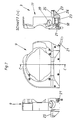
- die Haltevorrichtung samt Abdeckvorrichtung mit einem Schnitt,
- Fig. 4
- das erste Abdeckteil in Ansichten und in einem Schnitt,
- Fig. 5
- eine 3D-Ansicht des zweiten Abdeckteiles mit abgedeckter Auffangwanne,
- Fig. 6
- eine 3D-Ansicht des zweiten Abdeckteiles mit offener Auffangwanne und
- Fig. 7
- das zweite Abdeckteil in Ansichten und in einem Schnitt.
- In
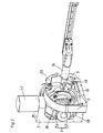
Fig. 1 ist eine Bearbeitungsvorrichtung 1 dargestellt, die ein rahmenförmiges Gehäuse 2 aufweist. Dieses Gehäuse 2 kann Wände z.B. aus Glas aufweisen. In diesem Gehäuse 2 sind auf der rechten Seite die wesentlichen Antriebselemente für das Bearbeitungswerkzeug 5 dargestellt, auf die nicht näher eingegangen wird. Auf der linken Seite ist der Bereich dargestellt, in dem der zu bearbeitende Formrohling 4 angeordnet ist. Zwischen diesen beiden Bereichen befindet sich eine Trennwand 15, in welcher eine Durchtrittsöffnung 16 für das Bearbeitungswerkzeug 5 ausgebildet ist. In dieser Durchtrittsöffnung 16 sind nachgiebige Bürsten angeordnet, sodass zwar das Bearbeitungswerkzeug 5 durchfahren kann, jedoch kaum Staub oder Flüssigkeit aus dem linken Bereich austreten kann. Der linke Bereich weist ein entlang einer vertikalen Achse verfahrbares Trägerelement 7 auf. Dieses Trägerelement 7 ist C-förmig ausgebildet. Am oberen Ende dieses C-förmigen Trägerelementes 7 ist ein Antriebselement 17 angeordnet, durch welches die Haltevorrichtung 3 um eine vertikale Achse drehbar ist. Im vom Bearbeitungswerkzeug 5 abgewandten Bereich der Haltevorrichtung 3 ist das schalenförmige Abdeckteil 8 angebracht. Im dem Bearbeitungswerkzeug 5 zugewandten Bereich der Haltevorrichtung 3 ist das ringförmige Abdeckteil 9 angebracht. Diese beiden Abdeckteile 8 und 9 bilden gemeinsam die Abdeckvorrichtung 6 und sind durch die Verbindungsbolzen 18 miteinander verbunden. - In
Fig. 2 ist ersichtlich, dass die Haltevorrichtung 3 zweiteilig ausgebildet ist und einen um die vertikale Achse drehbaren Außenring 13 und einen um eine vorzugsweise horizontale Achse drehbaren und von der Antriebsvorrichtung 20 antreibbaren Innenring 12 aufweist. Es ist aus dieserFig. 2 auch ersichtlich, dass das zweite Abdeckteil 9 eine Auffangwanne 10 aufweist. Zudem ist in diesem zweiten Abdeckteil 9 eine Luftabsaugöffnung 19 ausgebildet. Am Bearbeitungswerkzeug 5 ist strichliert eine Zuführeinrichtung 14 für eine Flüssigkeit angedeutet. Im Bereich der Spindel des Bearbeitungswerkzeuges 5 wird die Flüssigkeit in Richtung Bearbeitungsbereich B gespritzt. - In
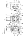
Fig. 3 ist dieser Bearbeitungsbereich B angedeutet und wird im Wesentlichen vom Innenring 12 begrenzt. In diesen Bearbeitungsbereich B wird der inFig. 3 strichliert angedeutete Formrohling 4 über eine nicht dargestellte Halteplatte an den Befestigungselementen 27 aufgespannt. Im rechten unteren Bereich ist am zweiten Abdeckteil 9 zum einen der Stutzen 22 für die Luftabsaugung und der Abflussschlauch 21 aus der Auffangwanne 10 angebracht. Der zweite Abdeckteil 9 ist über die Befestigungselemente 30 am Außenring 13 befestigt, vorzugsweise verschraubt. Das erste Abdeckteil 8 ist dagegen über die Verbindungsbolzen 18 direkt mit dem zweiten Abdeckteil 9 verbunden, vorzugsweise verschraubt. - Im Schnitt A-A ist zwischen dem Befestigungsbereich B und dem Trägerelement 7 das erste Abdeckteil 8 der Abdeckvorrichtung 6 ersichtlich. Dieser schüsselförmige erste Abdeckteil 8 umgibt gemeinsam mit dem Außenring 13 die gesamte vom Bearbeitungswerkzeug 5 abgewandte Seite des Bearbeitungsbereichs B. Nach vorne in Richtung Bearbeitungswerkzeug 5 wird der Bearbeitungsbereich B vom ringförmigen zweiten Abdeckteil 9 teilweise umgeben. Da aufgrund von Versuchen nur sehr wenig Flüssigkeit in Richtung Bearbeitungswerkzeug 5 zurückspritzt, kann die Abdeckvorrichtung 6 eine Öffnung 11 aufweisen. Das gesamte im hinteren Bereich und im vorderen Bereich aufgefangene Wasser fließt in Richtung Auffangwanne 10 zusammen. Gemäß Schnitt A-A ist die Auffangwanne 10 allerdings noch durch ein Schutzblech 23 geschützt. Dieses Schutzblech 23 ist nur dann angebracht, wenn der Formrohling 4 "trocken" bearbeitet wird, um ein Verstauben des Abflussschlauches 21 zu verhindern. Wenn dieses Schutzblech 23 entfernt ist, kann zusammenfließendes Wasser ungehindert in die Auffangwanne 10 und weiter über den Abflussschlauch 21 abgeführt werden. Am zweiten Abdeckteil 9 ist ein Aufsatz 29 befestigt, der ein bürstenförmiges Schutzelement 25 und eine Abfließschräge 26 aufweist. Der Außenring 13 ist über das Drehgelenk 24 drehbar am Trägerelement 7 gelagert.
- Beim Umrüsten von einer "trockenen" Bearbeitungsvorrichtung 1 auf eine "nasse" Bearbeitungsvorrichtung 1 müssen die Abstände zwischen den einzelnen Komponenten berücksichtigt werden. Vor allem zwischen dem Innenring 13 und dem Trägerelement 7 ist im vom Bearbeitungswerkzeug 5 abgewandten Bereich des Befestigungsbereichs B ein sehr geringer Abstand gegeben, sodass sich dazwischen nicht genügend Platz für eine relativ dicke und formstabile Ausbildung des ersten Abdeckteils 8 verbleibt (siehe Schnitt A-A). Um ein solches Umrüsten dennoch zu ermöglichen, ist in diesem ersten Abdeckteil ein reißfestes elastisches Element 28 (z.B. ein Tuch oder eine Plastikfolie) eingespannt bzw. angebracht. In
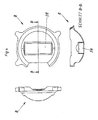
Fig. 4 ist dieses erste Abdeckteil 8 mitsamt dem elastischen Element 28 gezeigt. Es ist auch die Schalenförmigkeit dieses ersten Abdeckteils 8 ersichtlich. - In
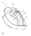
Fig. 5 ist eine 3D-Ansicht des zweiten Abdeckteils 9 mit der Öffnung 11, dem bürstenförmigen Schutzelement 25 und der Luftabsaugöffnung 19 gezeigt. Dabei ist die Auffangwanne 10 durch das Schutzblech 23 abgedeckt. - Demgegenüber ist in
Fig. 6 das Schutzblech 23 nur strichliert dargestellt bzw. entfernt, wodurch die Auffangwanne 10 offen ist. Bei der dadurch möglichen "nassen" Benützung der Bearbeitungsvorrichtung 1 sollte die Luftabsaugöffnung 19 durch einen hier nicht dargestellten Deckel verschlossen sein. - In
Fig. 7 ist nochmals das Trägerelement 7 samt Abflussschlauch 21, Auffangwanne 10 und Aufsatz 29 ersichtlich. Grundsätzlich kann jedes Abdeckteil 8 oder 9 ein- oder mehrteilig sein.
Claims (9)
- Bearbeitungsvorrichtung (1) für die Herstellung von zahntechnischen Werkstücken, mit- einem Gehäuse (2),- einer relativ zum Gehäuse (2) bewegbaren Haltevorrichtung (3) für einen Formrohling (4) und- einem Bearbeitungswerkzeug (5), mit dem unter Zufuhr von Flüssigkeit, insbesondere Wasser, in einem Bearbeitungsbereich (B) der Formrohling (4) bearbeitbar ist,
wobei der Bearbeitungsbereich (B) von einer vom Gehäuse (2) gesonderten Abdeckvorrichtung (6) zumindest teilweise umgeben ist, wobei die Abdeckvorrichtung (6) an der Haltevorrichtung (3) befestigt und mit der Haltevorrichtung (3) mit bewegbar ist, dadurch gekennzeichnet, dass die Abdeckvorrichtung (6) einen ersten Abdeckteil (8) und einen zweiten Abdeckteil (9) aufweist, wobei der erste, vorzugsweise schalenförmige, Abdeckteil (8) die vom Bearbeitungswerkzeug (5) abgewandte Seite des Bearbeitungsbereichs (B) abdeckt und der zweite, vorzugsweise ringförmige, Abdeckteil (9) die dem Bearbeitungswerkzeug (5) zugewandte Seite des Bearbeitungsbereichs (B) umgibt. - Bearbeitungsvorrichtung nach Anspruch 1, dadurch gekennzeichnet, dass die Haltevorrichtung (3) an einem am Gehäuse (2) befestigten Trägerelement (7) bewegbar gelagert ist.
- Bearbeitungsvorrichtung nach Anspruch 2, dadurch gekennzeichnet, dass die Abdeckvorrichtung (6) zwischen Trägerelement (7) und Bearbeitungsbereich (B) angeordnet ist.
- Bearbeitungsvorrichtung nach einem der Ansprüche 1 bis 3, dadurch gekennzeichnet, dass die Haltevorrichtung (3) die Abdeckvorrichtung (6) mitbildet.
- Bearbeitungswerkzeug nach einem der Ansprüche 1 bis 4, dadurch gekennzeichnet, dass der zweite Abdeckteil (9) eine Auffangwanne (10) für die Flüssigkeit aufweist.
- Bearbeitungsvorrichtung nach einem der Ansprüche 1 bis 5, dadurch gekennzeichnet, dass die Abdeckvorrichtung (6) auf der dem Bearbeitungswerkzeug (5) zugewandten Seite eine Öffnung (11) aufweist.
- Bearbeitungsvorrichtung nach Anspruch 6, dadurch gekennzeichnet, dass der Bearbeitungsbereich (B) bis auf die Öffnung (11) von der Abdeckvorrichtung (6) umgeben bzw. verschlossen ist.
- Bearbeitungsvorrichtung nach einem der Ansprüche 1 bis 7, dadurch gekennzeichnet, dass die Haltevorrichtung (3) einen Innenring (12) und einen Außenring (13) aufweist, die kardangelenkförmig angeordnet sind, wobei die Abdeckvorrichtung (6) am Außenring (13) befestigt ist.
- Bearbeitungsvorrichtung nach einem der Ansprüche 1 bis 8, dadurch gekennzeichnet, dass am Bearbeitungswerkzeug (5) eine Zuführeinrichtung (14) für die Flüssigkeit angeordnet ist.
Applications Claiming Priority (1)
| Application Number | Priority Date | Filing Date | Title |
|---|---|---|---|
| AT1872012A AT513082B1 (de) | 2012-02-14 | 2012-02-14 | Bearbeitungsvorrichtung für die herstellung von zahntechnischen werkstücken |
Publications (2)
| Publication Number | Publication Date |
|---|---|
| EP2628566A1 EP2628566A1 (de) | 2013-08-21 |
| EP2628566B1 true EP2628566B1 (de) | 2015-11-18 |
Family
ID=47738976
Family Applications (1)
| Application Number | Title | Priority Date | Filing Date |
|---|---|---|---|
| EP13000616.6A Not-in-force EP2628566B1 (de) | 2012-02-14 | 2013-02-07 | Bearbeitungsvorrichtung für die Herstellung von zahntechnischen Werkstücken |
Country Status (2)
| Country | Link |
|---|---|
| EP (1) | EP2628566B1 (de) |
| AT (1) | AT513082B1 (de) |
Cited By (1)
| Publication number | Priority date | Publication date | Assignee | Title |
|---|---|---|---|---|
| WO2021048299A1 (de) | 2019-09-12 | 2021-03-18 | Heinrich Steger | Haltevorrichtung für ein dentales werkstück |
Families Citing this family (5)
| Publication number | Priority date | Publication date | Assignee | Title |
|---|---|---|---|---|
| ITAL20120003A1 (it) * | 2012-05-10 | 2013-11-11 | Secondino Maccagno | Attrezzatura per la lavorazione in umido denominata fix and go |
| LU92420B1 (de) * | 2014-04-02 | 2015-10-05 | Vhf Camfacture Ag | Rechnergesteuerte Werkzeugmaschine zur Herstellungvon kleinen Werkst}cken |
| AT515412B1 (de) * | 2014-04-15 | 2015-09-15 | Steger Heinrich | CNC-Maschine |
| CN107170386B (zh) * | 2017-05-31 | 2023-04-14 | Oppo广东移动通信有限公司 | 灯箱布及灯箱 |
| AT519962B1 (de) * | 2017-06-13 | 2018-12-15 | Steger Heinrich | Bearbeitungsmaschine für die Herstellung von zahntechnischen Werkstücken |
Family Cites Families (7)
| Publication number | Priority date | Publication date | Assignee | Title |
|---|---|---|---|---|
| DE7835355U1 (de) * | 1980-05-08 | Rager, Richard, 8901 Neusaess | Vorrichtung zur Bearbeitung von zahntechnischen Modellen unter Verwendung eines rotierenden Abtragungswerkzeuges | |
| US3703124A (en) * | 1971-06-07 | 1972-11-21 | William Smith | Machine tool guard and/or safety shield |
| CH682990A5 (de) * | 1989-06-13 | 1993-12-31 | Mikrona Technologie Ag | Verfahren zur Herstellung eines Formkörpers, insbesondere zur Herstellung von Inlays, Onlays und Kronen in der Zahnmedizin sowie Gerät zur Durchführung des Verfahrens. |
| CH686657A5 (de) * | 1991-11-17 | 1996-05-31 | Liconic Ag | Verfahren zur Herstellung eines partiellen Ersatzes eines Zahnes und Einrichtung zur Durchfuehrung des Verfahrens. |
| DE102005016531A1 (de) * | 2005-04-08 | 2006-10-12 | Georg Schick Dental Gmbh | Absaugwanne für Werkstoffbearbeitungsmaschinen, insbesondere für Dentalfräsgeräte |
| DE102005058347B4 (de) * | 2005-12-06 | 2014-10-23 | Schwäbische Werkzeugmaschinen GmbH | Werkzeugmaschine zur Bearbeitung von Werkstücken |
| AT506486B1 (de) | 2008-02-15 | 2013-03-15 | Steger Heinrich | Aufspannvorrichtung für eine rechnergesteuerte, spanabhebende bearbeitungsmaschine |
-
2012
- 2012-02-14 AT AT1872012A patent/AT513082B1/de not_active IP Right Cessation
-
2013
- 2013-02-07 EP EP13000616.6A patent/EP2628566B1/de not_active Not-in-force
Cited By (1)
| Publication number | Priority date | Publication date | Assignee | Title |
|---|---|---|---|---|
| WO2021048299A1 (de) | 2019-09-12 | 2021-03-18 | Heinrich Steger | Haltevorrichtung für ein dentales werkstück |
Also Published As
| Publication number | Publication date |
|---|---|
| EP2628566A1 (de) | 2013-08-21 |
| AT513082A1 (de) | 2014-01-15 |
| AT513082B1 (de) | 2014-06-15 |
Similar Documents
| Publication | Publication Date | Title |
|---|---|---|
| AT513082B1 (de) | Bearbeitungsvorrichtung für die herstellung von zahntechnischen werkstücken | |
| DE3139962C2 (de) | Werkzeugmaschine mit Spanfördereinrichtung | |
| EP2488327B1 (de) | Abschirmungsvorrichtung an einem bearbeitungskopf sowie bearbeitungskopf und bearbeitungsmaschine mit einer abschirmungsvorrichtung | |
| DE102014108548B4 (de) | Verstreuschutzabdeckung für eine Werkzeugmaschine | |
| DE102012018226A1 (de) | Werkzeugmaschine mit Schutzabdeckung | |
| DE102009026935A1 (de) | Härtemaschine zum induktiven Härten unter Schutzgas | |
| DE19547085C2 (de) | Läpp- oder Poliermaschine | |
| EP0855245A1 (de) | Werkzeugmaschine mit einer Spülvorrichtung | |
| DE3203738A1 (de) | Vorrichtung zum abdecken von gleit- und fuehrungsschienen bei werkzeugmaschinen | |
| EP3081331B1 (de) | Dentalfräsmaschine | |
| DE3104065A1 (de) | Werkzeugmaschine | |
| EP0925817A1 (de) | Abspülbares Filter | |
| DE102014102071B4 (de) | Werkzeugmaschine mit Spanabstreifer | |
| DE19861132B4 (de) | Werkzeugmaschine mit Abdeckung | |
| DE102016101744A1 (de) | Kameraanordnung eines Kraftfahrzeugs | |
| EP3090831A1 (de) | Werkzeugschnellwechselsystem mit späneleiteinrichtung | |
| DE102014013129A1 (de) | Werkzeugmaschine zur spanabhebenden Bearbeitung eines Werkstücks mittels einer Minimalmengenschmierung sowie Verfahren zur Reinigung einer derartigen Werkzeugmaschine | |
| DE102004045078A1 (de) | Tank | |
| EP0232532A2 (de) | Fliehkraftbearbeitungsmaschine | |
| DE2613160A1 (de) | Schutzvorrichtung fuer schleifmaschinen | |
| DE19613443A1 (de) | Tiefbohreinheit mit Späneauffangbehälter | |
| DE10136778C2 (de) | Rundarbeitstisch mit mehreren Arbeitspositionen | |
| DE10011941A1 (de) | Bearbeitungsmaschine zur materialabtragenden Bearbeitung eines Werkstücks | |
| DE9013621U1 (de) | Werkzeugmaschine mit einer Teleskopabdeckung auf dem Maschinenbett zur Ableitung von Kühlmittel | |
| EP1709941A1 (de) | Absaugwanne für Werkstoffbearbeitungsmaschinen, insbesondere für Dentalfräsgeräte |
Legal Events
| Date | Code | Title | Description |
|---|---|---|---|
| PUAI | Public reference made under article 153(3) epc to a published international application that has entered the european phase |
Free format text: ORIGINAL CODE: 0009012 |
|
| AK | Designated contracting states |
Kind code of ref document: A1 Designated state(s): AL AT BE BG CH CY CZ DE DK EE ES FI FR GB GR HR HU IE IS IT LI LT LU LV MC MK MT NL NO PL PT RO RS SE SI SK SM TR |
|
| AX | Request for extension of the european patent |
Extension state: BA ME |
|
| 17P | Request for examination filed |
Effective date: 20140212 |
|
| RBV | Designated contracting states (corrected) |
Designated state(s): AL AT BE BG CH CY CZ DE DK EE ES FI FR GB GR HR HU IE IS IT LI LT LU LV MC MK MT NL NO PL PT RO RS SE SI SK SM TR |
|
| 17Q | First examination report despatched |
Effective date: 20140326 |
|
| GRAP | Despatch of communication of intention to grant a patent |
Free format text: ORIGINAL CODE: EPIDOSNIGR1 |
|
| INTG | Intention to grant announced |
Effective date: 20150622 |
|
| GRAS | Grant fee paid |
Free format text: ORIGINAL CODE: EPIDOSNIGR3 |
|
| GRAA | (expected) grant |
Free format text: ORIGINAL CODE: 0009210 |
|
| AK | Designated contracting states |
Kind code of ref document: B1 Designated state(s): AL AT BE BG CH CY CZ DE DK EE ES FI FR GB GR HR HU IE IS IT LI LT LU LV MC MK MT NL NO PL PT RO RS SE SI SK SM TR |
|
| REG | Reference to a national code |
Ref country code: GB Ref legal event code: FG4D Free format text: NOT ENGLISH |
|
| REG | Reference to a national code |
Ref country code: CH Ref legal event code: EP |
|
| REG | Reference to a national code |
Ref country code: AT Ref legal event code: REF Ref document number: 761277 Country of ref document: AT Kind code of ref document: T Effective date: 20151215 |
|
| REG | Reference to a national code |
Ref country code: IE Ref legal event code: FG4D Free format text: LANGUAGE OF EP DOCUMENT: GERMAN |
|
| REG | Reference to a national code |
Ref country code: DE Ref legal event code: R096 Ref document number: 502013001463 Country of ref document: DE |
|
| REG | Reference to a national code |
Ref country code: FR Ref legal event code: PLFP Year of fee payment: 4 |
|
| REG | Reference to a national code |
Ref country code: NL Ref legal event code: MP Effective date: 20160218 |
|
| REG | Reference to a national code |
Ref country code: LT Ref legal event code: MG4D |
|
| PG25 | Lapsed in a contracting state [announced via postgrant information from national office to epo] |
Ref country code: NL Free format text: LAPSE BECAUSE OF FAILURE TO SUBMIT A TRANSLATION OF THE DESCRIPTION OR TO PAY THE FEE WITHIN THE PRESCRIBED TIME-LIMIT Effective date: 20151118 Ref country code: NO Free format text: LAPSE BECAUSE OF FAILURE TO SUBMIT A TRANSLATION OF THE DESCRIPTION OR TO PAY THE FEE WITHIN THE PRESCRIBED TIME-LIMIT Effective date: 20160218 Ref country code: IS Free format text: LAPSE BECAUSE OF FAILURE TO SUBMIT A TRANSLATION OF THE DESCRIPTION OR TO PAY THE FEE WITHIN THE PRESCRIBED TIME-LIMIT Effective date: 20160318 Ref country code: LT Free format text: LAPSE BECAUSE OF FAILURE TO SUBMIT A TRANSLATION OF THE DESCRIPTION OR TO PAY THE FEE WITHIN THE PRESCRIBED TIME-LIMIT Effective date: 20151118 Ref country code: HR Free format text: LAPSE BECAUSE OF FAILURE TO SUBMIT A TRANSLATION OF THE DESCRIPTION OR TO PAY THE FEE WITHIN THE PRESCRIBED TIME-LIMIT Effective date: 20151118 Ref country code: ES Free format text: LAPSE BECAUSE OF FAILURE TO SUBMIT A TRANSLATION OF THE DESCRIPTION OR TO PAY THE FEE WITHIN THE PRESCRIBED TIME-LIMIT Effective date: 20151118 |
|
| PGFP | Annual fee paid to national office [announced via postgrant information from national office to epo] |
Ref country code: DE Payment date: 20160201 Year of fee payment: 4 Ref country code: IT Payment date: 20160229 Year of fee payment: 4 |
|
| PG25 | Lapsed in a contracting state [announced via postgrant information from national office to epo] |
Ref country code: FI Free format text: LAPSE BECAUSE OF FAILURE TO SUBMIT A TRANSLATION OF THE DESCRIPTION OR TO PAY THE FEE WITHIN THE PRESCRIBED TIME-LIMIT Effective date: 20151118 Ref country code: RS Free format text: LAPSE BECAUSE OF FAILURE TO SUBMIT A TRANSLATION OF THE DESCRIPTION OR TO PAY THE FEE WITHIN THE PRESCRIBED TIME-LIMIT Effective date: 20151118 Ref country code: PT Free format text: LAPSE BECAUSE OF FAILURE TO SUBMIT A TRANSLATION OF THE DESCRIPTION OR TO PAY THE FEE WITHIN THE PRESCRIBED TIME-LIMIT Effective date: 20160318 Ref country code: BE Free format text: LAPSE BECAUSE OF NON-PAYMENT OF DUE FEES Effective date: 20160229 Ref country code: LV Free format text: LAPSE BECAUSE OF FAILURE TO SUBMIT A TRANSLATION OF THE DESCRIPTION OR TO PAY THE FEE WITHIN THE PRESCRIBED TIME-LIMIT Effective date: 20151118 Ref country code: GR Free format text: LAPSE BECAUSE OF FAILURE TO SUBMIT A TRANSLATION OF THE DESCRIPTION OR TO PAY THE FEE WITHIN THE PRESCRIBED TIME-LIMIT Effective date: 20160219 Ref country code: PL Free format text: LAPSE BECAUSE OF FAILURE TO SUBMIT A TRANSLATION OF THE DESCRIPTION OR TO PAY THE FEE WITHIN THE PRESCRIBED TIME-LIMIT Effective date: 20151118 Ref country code: SE Free format text: LAPSE BECAUSE OF FAILURE TO SUBMIT A TRANSLATION OF THE DESCRIPTION OR TO PAY THE FEE WITHIN THE PRESCRIBED TIME-LIMIT Effective date: 20151118 |
|
| PGFP | Annual fee paid to national office [announced via postgrant information from national office to epo] |
Ref country code: FR Payment date: 20160202 Year of fee payment: 4 |
|
| PG25 | Lapsed in a contracting state [announced via postgrant information from national office to epo] |
Ref country code: CZ Free format text: LAPSE BECAUSE OF FAILURE TO SUBMIT A TRANSLATION OF THE DESCRIPTION OR TO PAY THE FEE WITHIN THE PRESCRIBED TIME-LIMIT Effective date: 20151118 |
|
| REG | Reference to a national code |
Ref country code: DE Ref legal event code: R097 Ref document number: 502013001463 Country of ref document: DE |
|
| PG25 | Lapsed in a contracting state [announced via postgrant information from national office to epo] |
Ref country code: SM Free format text: LAPSE BECAUSE OF FAILURE TO SUBMIT A TRANSLATION OF THE DESCRIPTION OR TO PAY THE FEE WITHIN THE PRESCRIBED TIME-LIMIT Effective date: 20151118 Ref country code: SK Free format text: LAPSE BECAUSE OF FAILURE TO SUBMIT A TRANSLATION OF THE DESCRIPTION OR TO PAY THE FEE WITHIN THE PRESCRIBED TIME-LIMIT Effective date: 20151118 Ref country code: EE Free format text: LAPSE BECAUSE OF FAILURE TO SUBMIT A TRANSLATION OF THE DESCRIPTION OR TO PAY THE FEE WITHIN THE PRESCRIBED TIME-LIMIT Effective date: 20151118 Ref country code: DK Free format text: LAPSE BECAUSE OF FAILURE TO SUBMIT A TRANSLATION OF THE DESCRIPTION OR TO PAY THE FEE WITHIN THE PRESCRIBED TIME-LIMIT Effective date: 20151118 Ref country code: RO Free format text: LAPSE BECAUSE OF FAILURE TO SUBMIT A TRANSLATION OF THE DESCRIPTION OR TO PAY THE FEE WITHIN THE PRESCRIBED TIME-LIMIT Effective date: 20151118 |
|
| PLBE | No opposition filed within time limit |
Free format text: ORIGINAL CODE: 0009261 |
|
| STAA | Information on the status of an ep patent application or granted ep patent |
Free format text: STATUS: NO OPPOSITION FILED WITHIN TIME LIMIT |
|
| PG25 | Lapsed in a contracting state [announced via postgrant information from national office to epo] |
Ref country code: LU Free format text: LAPSE BECAUSE OF FAILURE TO SUBMIT A TRANSLATION OF THE DESCRIPTION OR TO PAY THE FEE WITHIN THE PRESCRIBED TIME-LIMIT Effective date: 20160207 Ref country code: MC Free format text: LAPSE BECAUSE OF FAILURE TO SUBMIT A TRANSLATION OF THE DESCRIPTION OR TO PAY THE FEE WITHIN THE PRESCRIBED TIME-LIMIT Effective date: 20151118 |
|
| REG | Reference to a national code |
Ref country code: CH Ref legal event code: PL |
|
| 26N | No opposition filed |
Effective date: 20160819 |
|
| PG25 | Lapsed in a contracting state [announced via postgrant information from national office to epo] |
Ref country code: CH Free format text: LAPSE BECAUSE OF NON-PAYMENT OF DUE FEES Effective date: 20160229 Ref country code: LI Free format text: LAPSE BECAUSE OF NON-PAYMENT OF DUE FEES Effective date: 20160229 |
|
| PG25 | Lapsed in a contracting state [announced via postgrant information from national office to epo] |
Ref country code: SI Free format text: LAPSE BECAUSE OF FAILURE TO SUBMIT A TRANSLATION OF THE DESCRIPTION OR TO PAY THE FEE WITHIN THE PRESCRIBED TIME-LIMIT Effective date: 20151118 |
|
| REG | Reference to a national code |
Ref country code: IE Ref legal event code: MM4A |
|
| PG25 | Lapsed in a contracting state [announced via postgrant information from national office to epo] |
Ref country code: IE Free format text: LAPSE BECAUSE OF NON-PAYMENT OF DUE FEES Effective date: 20160207 |
|
| PG25 | Lapsed in a contracting state [announced via postgrant information from national office to epo] |
Ref country code: MT Free format text: LAPSE BECAUSE OF FAILURE TO SUBMIT A TRANSLATION OF THE DESCRIPTION OR TO PAY THE FEE WITHIN THE PRESCRIBED TIME-LIMIT Effective date: 20151118 |
|
| REG | Reference to a national code |
Ref country code: DE Ref legal event code: R119 Ref document number: 502013001463 Country of ref document: DE |
|
| GBPC | Gb: european patent ceased through non-payment of renewal fee |
Effective date: 20170207 |
|
| REG | Reference to a national code |
Ref country code: FR Ref legal event code: ST Effective date: 20171031 |
|
| PG25 | Lapsed in a contracting state [announced via postgrant information from national office to epo] |
Ref country code: DE Free format text: LAPSE BECAUSE OF NON-PAYMENT OF DUE FEES Effective date: 20170901 Ref country code: FR Free format text: LAPSE BECAUSE OF NON-PAYMENT OF DUE FEES Effective date: 20170228 |
|
| PG25 | Lapsed in a contracting state [announced via postgrant information from national office to epo] |
Ref country code: IT Free format text: LAPSE BECAUSE OF NON-PAYMENT OF DUE FEES Effective date: 20170207 Ref country code: GB Free format text: LAPSE BECAUSE OF NON-PAYMENT OF DUE FEES Effective date: 20170207 |
|
| PG25 | Lapsed in a contracting state [announced via postgrant information from national office to epo] |
Ref country code: CY Free format text: LAPSE BECAUSE OF FAILURE TO SUBMIT A TRANSLATION OF THE DESCRIPTION OR TO PAY THE FEE WITHIN THE PRESCRIBED TIME-LIMIT Effective date: 20151118 Ref country code: HU Free format text: LAPSE BECAUSE OF FAILURE TO SUBMIT A TRANSLATION OF THE DESCRIPTION OR TO PAY THE FEE WITHIN THE PRESCRIBED TIME-LIMIT; INVALID AB INITIO Effective date: 20130207 |
|
| PG25 | Lapsed in a contracting state [announced via postgrant information from national office to epo] |
Ref country code: MK Free format text: LAPSE BECAUSE OF FAILURE TO SUBMIT A TRANSLATION OF THE DESCRIPTION OR TO PAY THE FEE WITHIN THE PRESCRIBED TIME-LIMIT Effective date: 20151118 Ref country code: TR Free format text: LAPSE BECAUSE OF FAILURE TO SUBMIT A TRANSLATION OF THE DESCRIPTION OR TO PAY THE FEE WITHIN THE PRESCRIBED TIME-LIMIT Effective date: 20151118 |
|
| PG25 | Lapsed in a contracting state [announced via postgrant information from national office to epo] |
Ref country code: BG Free format text: LAPSE BECAUSE OF FAILURE TO SUBMIT A TRANSLATION OF THE DESCRIPTION OR TO PAY THE FEE WITHIN THE PRESCRIBED TIME-LIMIT Effective date: 20151118 |
|
| PG25 | Lapsed in a contracting state [announced via postgrant information from national office to epo] |
Ref country code: AL Free format text: LAPSE BECAUSE OF FAILURE TO SUBMIT A TRANSLATION OF THE DESCRIPTION OR TO PAY THE FEE WITHIN THE PRESCRIBED TIME-LIMIT Effective date: 20151118 |
|
| REG | Reference to a national code |
Ref country code: AT Ref legal event code: MM01 Ref document number: 761277 Country of ref document: AT Kind code of ref document: T Effective date: 20180207 |
|
| PG25 | Lapsed in a contracting state [announced via postgrant information from national office to epo] |
Ref country code: AT Free format text: LAPSE BECAUSE OF NON-PAYMENT OF DUE FEES Effective date: 20180207 |