EP2628577B1 - Vorrichtung zum Wechseln des Oberwerkzeugs einer Stanzmaschine - Google Patents
Vorrichtung zum Wechseln des Oberwerkzeugs einer Stanzmaschine Download PDFInfo
- Publication number
- EP2628577B1 EP2628577B1 EP13153729.2A EP13153729A EP2628577B1 EP 2628577 B1 EP2628577 B1 EP 2628577B1 EP 13153729 A EP13153729 A EP 13153729A EP 2628577 B1 EP2628577 B1 EP 2628577B1
- Authority
- EP
- European Patent Office
- Prior art keywords
- changing
- punching
- braking
- upper tool
- locking unit
- Prior art date
- Legal status (The legal status is an assumption and is not a legal conclusion. Google has not performed a legal analysis and makes no representation as to the accuracy of the status listed.)
- Active
Links
Images

Classifications
-
- B—PERFORMING OPERATIONS; TRANSPORTING
- B26—HAND CUTTING TOOLS; CUTTING; SEVERING
- B26D—CUTTING; DETAILS COMMON TO MACHINES FOR PERFORATING, PUNCHING, CUTTING-OUT, STAMPING-OUT OR SEVERING
- B26D7/00—Details of apparatus for cutting, cutting-out, stamping-out, punching, perforating, or severing by means other than cutting
- B26D7/26—Means for mounting or adjusting the cutting member; Means for adjusting the stroke of the cutting member
-
- B—PERFORMING OPERATIONS; TRANSPORTING
- B26—HAND CUTTING TOOLS; CUTTING; SEVERING
- B26D—CUTTING; DETAILS COMMON TO MACHINES FOR PERFORATING, PUNCHING, CUTTING-OUT, STAMPING-OUT OR SEVERING
- B26D7/00—Details of apparatus for cutting, cutting-out, stamping-out, punching, perforating, or severing by means other than cutting
- B26D7/27—Means for performing other operations combined with cutting
-
- B—PERFORMING OPERATIONS; TRANSPORTING
- B26—HAND CUTTING TOOLS; CUTTING; SEVERING
- B26D—CUTTING; DETAILS COMMON TO MACHINES FOR PERFORATING, PUNCHING, CUTTING-OUT, STAMPING-OUT OR SEVERING
- B26D7/00—Details of apparatus for cutting, cutting-out, stamping-out, punching, perforating, or severing by means other than cutting
- B26D7/26—Means for mounting or adjusting the cutting member; Means for adjusting the stroke of the cutting member
- B26D2007/2607—Means for mounting or adjusting the cutting member; Means for adjusting the stroke of the cutting member for mounting die cutters
Definitions
- the invention relates to a device for changing the upper tool of a punching and / or embossing station according to the preamble of claim 1.
- Punching is the term used to describe cutting with self-contained geometric cutting shapes, which can be circular, oval or polygonal as well as imaginative shapes of all kinds.
- the practices used in print finishing, such as punching with a punch, corner knocking off and register punching, are also included in this area.
- the punching takes place against a punching pad or against a stamp, sometimes there are also shearing processes.
- Packaging materials made of paper, cardboard, cardboard or corrugated cardboard are mainly punched in sheet format. During the punching process, however, creasing lines or blind embossing can also be made in the panel. This complex process makes it essential to punch the sheets individually. Since the end products are sophisticated packaging in terms of technical and graphic design (e.g.
- Such a flat bed punch is for example from DE 30 44 083 A1 or the US 7,658,378 B2 known.
- the two tables are equipped with cutting and creasing tools or corresponding counter-tools, with which the panels are punched out of the arches guided intermittently between the table surface and at the same time the creases necessary for clean folding are pressed.
- the waste is removed automatically using stripping tools.
- the punched copies can finally be separated in a dedicated depaneling device.
- a well-known flatbed sheet punching machine which from the DE 37 12 510 A1 is known, is additionally equipped with a handling device in order to make it easier for an operator to change tools at the individual processing stations of the punching machine.
- the handling device is designed here as a semi-automatic lifting device which is arranged on the operating platform of the machine and can be moved along it. The operator has the option of positioning the handling device at each of the processing stations and then extending a lifting fork in order to grip and position a tool.
- a tool magazine is assigned to the handling device, from which the tools can be removed or in which the tools that are no longer required can be stored. The tool magazine can be moved together with the handling device and, in particular, can be moved out of the operating area of the machine when it is not needed.
- the DE 694 02 653 T2 describes a method for exchanging punching tools in a crucible punch with the aid of a sliding carriage and the structure of this carriage.
- the chassis of the trolley is located below a platform on the operator's side of the crucible punch; Above the pedestal there is a device for receiving a punching tool to be changed.
- the receptacle is designed to be rotatable so that a punching tool can be provided in a horizontal position for the tool change.
- the mobility of the carriage ensures that the carriage can be moved from an outermost position on the edge of the platform to a transfer position directly in front of the punching station of the crucible punch.
- a device for changing tools of a crucible punch is also disclosed.
- it can be displaced on the platform on the operator's side along the crucible punch, ie parallel to it.
- the tool holder of the device is designed in such a way that two upper tools can be accommodated in it at the same time. By rotating the receptacle, one of the tools is brought into a transfer position in which the punching tool can be pushed into the punching station of the crucible punch.
- friction brakes are used, which act permanently on the rotatable tool holder.
- the machine operator has to work against the force of the friction brake when handling.
- the tool holder is locked in one of the two horizontal positions by means of locking bolts or the like. Means. These must be pulled out manually by the machine operator before turning the tool holder.
- the object of the present invention is therefore to create a device for changing the upper tool of a punching and / or embossing station which allows easier handling with greater safety for the machine operator.
- the device according to the invention for changing the upper tool of a punching and / or embossing station of a flatbed sheet punching and / or embossing machine is immediately adjacent to a punching and / or embossing station of the flatbed sheet punching and / or for the changing process of the upper tool - Embossing machine can be positioned.
- the device has a rotatable tool holder for receiving and providing the upper tool in a substantially horizontal supply plane.
- the upper tool can be a punching tool, creasing tool, stamping tool or a combined tool with several of the functions of stamping, creasing and stamping.
- the device for changing the upper tool has a braking and locking unit, a transmission system and an actuating button.
- the braking and locking unit is advantageously designed in such a way that it prevents or at least restricts the rotational mobility of the tool holder.
- the transmission system is arranged between the actuating button and the braking and locking unit and is used to transmit a force from the actuating button to the braking and locking unit.
- the actuation button is arranged at a distance from the braking and locking unit in an ergonomically favorable position.
- the actuation of the actuation button by the machine operator cancels the effect of the braking and locking unit. This advantageously ensures that the tool holder can be rotated by the machine operator without a great deal of force while the actuating button is being operated.
- the actuation button can in particular be positioned easily accessible on the tool holder and in particular in a rotary handle be integrated for turning the tool holder.
- the braking and locking unit acts on the tool holder, in that it is braked or completely locked when predetermined locking positions are reached. This significantly reduces the risk of injury to the machine operator while changing the upper tool.
- the transmission system has an actuator, the actuator canceling the effect of the braking and locking unit.
- This actuator can in particular be controlled by the actuating button.
- the brake and locking unit can have a brake disk and at least one brake pad, the at least one brake pad acting on the brake disk.
- the brake disk can be connected to the tool holder and can be rotated together with the tool holder. The brake pad then decelerates the brake disk and thus the tool holder during its rotary movement.
- the brake disc has at least two locking notches, which can be made on the circumference of the brake disc, for example, and in which the at least one brake pad can engage. These notches lock the brake disc in place.
- the locking of the brake disc simultaneously causes the tool holder to be locked.
- the brake disc is a circular disc, two locking notches can be arranged diametrically opposite one another on the circumference of the circular disc. After rotating the tool holder and thus the brake disc by 180 °, the brake block engages in the locking notch and can thus position and lock the tool holder in such a way that the tool is made available in the preparation plane.
- the braking and locking unit has a spring, the spring pressing the at least one brake pad against the brake disc.
- the actuator can act on the at least one brake pad and lift it off the brake disc.
- the actuator is activated by pressing the actuation button, the actuator lifts the brake pad from the brake disc and the effect of the brake and locking unit is thereby canceled.
- the effect of the braking and locking unit is only canceled as long as the machine operator presses the operating button.
- the actuating button is designed as a rotary handle at the same time, so that the machine operator both effects the rotary movement of the tool holder by grasping the rotary handle and actuates the actuating button and thus cancels the effect of the braking and locking unit.
- the braking and locking unit acts immediately and an uncontrolled and therefore dangerous further movement of the tool holder is prevented.
- the transmission system is designed to be electrical, so that there is no direct mechanical connection between the actuation button and the braking and locking unit.
- the actuator is advantageously designed as a controllable electric motor.
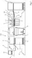
- FIG 1 shows the basic structure of a sheet punching and embossing machine 100 for punching, breaking, blanking and depositing sheets of paper, cardboard and the like.
- the punching and embossing machine 100 has a feeder 1, a punching station 2, a stripping station 3 and a boom 4, which are carried and enclosed by a common machine housing 5.
- the processing stations 2, 3, 4 are accessible from one side, the so-called operator side, via a walk-on platform 5.1;
- the drive train of the sheet punching and embossing machine 100 is located on the opposite side, the so-called drive side.
- the sheets 6 are separated from a stack by a feeder 1, fed to the sheet transport system 7 and gripped at their front edge by grippers attached to the gripper bridges of a gripper carriage 8 and intermittently through the various stations 2, 3 and 4 of the punching and embossing machine 100 in the sheet transport direction B pulled through.
- the sheet transport system 7 has several gripper carriages 8 so that several sheets 6 can be processed at the same time in the various stations 2, 3 and 4.
- the gripper carriages 8 can be driven by a chain drive or, in an alternative embodiment, by an electromagnetic linear drive with traveling field motors.
- the punching station 2 consists of a lower crucible, a so-called lower table 9, and an upper crucible, a so-called upper table 10.
- the upper table 10 can be moved vertically to and fro and is provided with a tool 30 with punching and scoring knives.
- the upper table 10 is driven by a drive 2.1.
- a device (not shown here) for changing the upper tool 40 Fig. 2 be executed shown.
- the lower table 9 is firmly mounted in the machine frame 5 and provided with a counter plate 20 for the punching and scoring knives.
- the gripper carriage 8 transports the sheet 6 from the punching and embossing station 2 to the subsequent stripping station 3, which is equipped with stripping tools.
- the stripping station 3 with the help of the stripping tools, the waste pieces that are not required are pushed out of the arch 6 downwards, as a result of which the waste pieces 11 fall into a carriage-like container 12 pushed under the station.
- the sheet 6 arrives at the delivery 4, where the sheet 6 is either simply deposited or the individual copies of a respective sheet 6 are separated at the same time.
- the boom 4 can also contain a pallet 13 on which the individual sheets 6 are stacked in the form of a stack 14, so that after a certain stack height has been reached, the pallet 13 with the sheet stack 14 can be moved away from the area of the punching and embossing machine 100 .
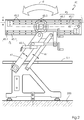
- Figure 2 shows an example of a device 40 for changing the upper tool: the device 40 stands on the machine foundation 200 and has arms 47 which are supported by a platform 5.1 attached in front of a sheet punching machine 100, also as a gallery marked, protrude through.
- the device 40 has two tool holders 45 at the upper ends of the arms 47.
- a respective tool holder 45 is formed by rails 45.1 into which an in Fig. 3 upper tool not shown can be inserted.
- a respective rail 45.1 has a plurality of rollers 45.2 on which an upper tool (not shown) can be moved with little friction.
- the upper tool holder 45 lies in a preparation plane r, from which an upper tool (not shown) can be transferred to a punching and / or embossing station 2 of a punching machine 100.
- a securing element designed here as a securing pin 45.3, is provided in each tool holder 45. This can be operated by hand.
- the tool holder 45 can be variable in its height level h ', for example moved by the motor 42.1, which acts as a height compensation drive
- Fig. 3 shows the device for changing the upper tool 40, a so-called chase frame changer, in a detailed view.
- a rotary handle 401 with an actuating button 406 is attached to the tool holder 45.
- a braking and locking unit 408 is arranged between the swivel arms 47 and the tool holder 45.
- the brake and locking unit 408 has a brake and switching disk 405 on which a brake pad 403 acts.
- the brake pad 403 is connected to a locking lever 402, which is acted upon by a spring 409, so that the brake pad 403 acts on the brake and switching disk 405.
- the effect of the spring 409 can be canceled by an actuator, designed here as a pneumatic cylinder 404.
- a pneumatic system 410 with a connection line from the actuating button 406 to the pneumatic cylinder 404 is provided.
- the pneumatic cylinder 404 is actuated, which deflects the lever 402 against the action of the spring 409, so that the brake pad 403 can no longer act on the brake disc 405.
- the braking and Switching disk 405 has, as shown, two locking notches 407 which are arranged on the circumference of the brake and switching disk 105 diametrically opposite one another.
- the brake pad 403 can engage in these latching notches 407 and thus prevent the brake and shift disk 405 from rotating.
- the two latching notches 407 thus represent switching positions of the brake and switching disk 405 in which rotation of the tool holder 45 is not possible.
- the brake and shift disc In the representation of Fig. 3 the brake and shift disc is currently in the locked state.
- the locking of the brake and switching disk 405 In order to be able to rotate the tool holder 45 and to be able to change the upper tools 10.1, the locking of the brake and switching disk 405 must be released by actuating the actuating button 406 by disengaging the brake pad 403.
- the locking positions defined by the locking notches 407 are selected so that one of the two guide rails 45.1 and thus one of the two upper tools 10.1, which are received in the guide rails 45.1, are in the supply plane r and thus a tool 30 from the device 40 to Changing the upper tool can be transferred to the punching and / or embossing station 2 of the punching machine 100.
Landscapes
- Life Sciences & Earth Sciences (AREA)
- Forests & Forestry (AREA)
- Engineering & Computer Science (AREA)
- Mechanical Engineering (AREA)
- Perforating, Stamping-Out Or Severing By Means Other Than Cutting (AREA)
- Bending Of Plates, Rods, And Pipes (AREA)
Description
- Die Erfindung betrifft eine Vorrichtung zum Wechseln des Oberwerkzeugs einer Stanz- und/oder -Prägestation gemäß dem Oberbegriff von Anspruch 1.
- Als Stanzen wird das Schneiden mit in sich geschlossenen geometrischen Zuschnittstormen bezeichnet, die kreisförmig, oval oder mehreckig sowie Phantasieformen aller Art sein können. Auch die in der Druckweiterverarbeitung geübten Praktiken, wie Stanzen mit Locheisen, Eckenabstoßen und Registerstanzen werden zu diesem Bereich gezählt. Die Stanzung erfolgt gegen eine Stanzunterlage oder gegen Stempel, teilweise sind es auch Schervorgänge. Verpackungsmaterialien aus Papier, Karton, Pappe oder Wellpappe werden hauptsächlich im Bogenformat gestanzt. Beim Stanzvorgang können zusätzlich aber auch Rilllinien oder Blindprägungen in den Nutzen eingebracht werden. Dieser komplexe Prozess macht es unabdingbar, die Bogen einzeln zu stanzen. Da es sich bei den Endprodukten um anspruchsvolle Verpackungen hinsichtlich technischer und graphischer Ausführung handelt (etwa Verpackungen für Kosmetik, Zigaretten, Pharmazie, Lebensmittel, etc.), werden besondere Anforderungen nicht nur an die Verpackungsmaterialien selbst gestellt, sondern es sind für optimale Resultate auch Stanzwerkzeuge mit geringsten Toleranzen und äußerst präzise und zuverlässig arbeitende Stanzmaschinen erforderlich. Diesen Ansprüchen wird das Flachbettstanzen am besten gerecht. Dabei werden die gedruckten und auf einer Palette gestapelten Bogen der Stanzmaschine zugeführt. In der Maschine werden in einer Ausrichteinrichtung die zu stanzenden Bogen passgenau ausgerichtet, von einem Greiferwagen übernommen und exakt in der Stanzeinrichtung zwischen einem fest gelagerten Untertisch und einem über einen Kniehebel oder Exzentergetriebe vertikal bewegbaren Obertisch positioniert.
- In bekannten Bogenstanz- und Prägemaschinen, die zum Stanzen, Prägen, Ausbrechen, ggfs. Nutzentrennen und Ablegen von Bögen aus Papier, Pappe und der gleichen eingesetzt werden, ist es bekannt die Bögen mittels Greiferwagen durch die einzelnen Stationen der Maschine zu bewegen. Ein jeweiliger Greiferwagen besitzt eine Greiferbrücke, an der Greifer befestigt sind, die die Bögen an einem vorderen Ende ergreifen. Ein Greiferwagen besitzt weiterhin seitliche Fahrwagen, welche mit endlosen Ketten des Transportsystems verbunden sind und wodurch die Greiferwagen durch die Maschine bewegt werden. Durch diese Art der Bewegung der Bögen durch die Maschine wird ein kontinuierliches Arbeiten in den einzelnen hintereinander angeordneten Stationen der Maschine, insbesondere Stanz-, Ausbrech- und Nutzentrennstation, ermöglicht.
- Eine derartige Flachbettstanze ist beispielsweise aus der
DE 30 44 083 A1 oder derUS 7,658,378 B2 bekannt. Die beiden Tische sind mit Schneid- und Rillwerkzeugen bzw. entsprechenden Gegenwerkzeugen bestückt, mit denen aus dem taktweise zwischen die Tischfläche geführten Bögen die Nutzen ausgestanzt und gleichzeitig die zum sauberen Falten notwendigen Rillen eingedrückt werden. In der nachfolgenden Ausbrecheinrichtung wird der Abfall über Ausbrechwerkzeuge maschinell entfernt. Je nach Ausstattung der Maschine können schließlich die gestanzten Nutzen in einer hierfür vorgesehenen Nutzentrenneinrichtung separiert werden. - Eine bekannte Flachbett-Bogenstanzmaschine, welche aus der
DE 37 12510 A1 bekannt ist, ist zusätzlich mit einer Handhabungseinrichtung ausgestattet, um einer Bedienungsperson einen Werkzeugwechsel an den einzelnen Bearbeitungsstationen der Stanzmaschine zu erleichtern. Die Handhabungseinrichtung ist hier als halbautomatische Hebevorrichtung ausgestaltet, welche an dem Bedienungspodest der Maschine angeordnet und entlang von dieser verfahrbar ist. Die Bedienungsperson hat die Möglichkeit, die Handhabungseinrichtung an jeder der Bearbeitungsstationen zu positionieren und dann eine Hubgabel auszufahren, um ein Werkzeug zu greifen und zu positionieren. Der Handhabungseinrichtung ist ein Werkzeugmagazin zugeordnet, aus welchem die Werkzeuge entnommen bzw. in dem die nicht mehr benötigten Werkzeuge abgelegt werden können. Das Werkzeugmagazin ist zusammen mit der Handhabungseinrichtung verfahrbar und kann insbesondere aus dem Bedienungsbereich der Maschine heraus bewegt werden, wenn es nicht benötigt wird. - Die
DE 694 02 653 T2 beschreibt ein Verfahren zum Austauschen von Stanzwerkzeugen in einer Tiegelstanze mit Hilfe eines verschiebbaren Wagens als auch den Aufbau dieses Wagens. Das Fahrgestell des Wagens befindet sich unterhalb eines Podestes auf der Bedienerseite der Tiegelstanze; oberhalb des Podestes befindet sich eine Einrichtung zur Aufnahme eines zu wechselnden Stanzwerkzeuges. Die Aufnahme ist drehbar gestaltet, sodass ein Stanzwerkzeug in einer horizontalen Position für den Werkzeugwechsel bereitgestellt werden kann. Durch die Verschieblichkeit des Wagens ist sichergestellt, dass der Wagen von einer äußersten Position am Rande des Podestes hin zu einer Übergabeposition direkt vor der Stanzstation der Tiegelstanze bewegt werden kann. - In der
DE 695 06 031 T2 ist ebenfalls eine Vorrichtung zum Werkzeugwechsel einer Tiegelstanze offenbart. Im Gegensatz zur zuvor beschriebenen Vorrichtung ist diese auf dem Podest auf der Bedienerseite entlang der Tiegelstanze, d.h. parallel zu ihr, verschieblich. Die Werkzeugaufnahme der Vorrichtung ist derart ausgeführt, dass zeitgleich zwei Oberwerkzeuge in ihr aufgenommen sein können. Durch eine Drehbewegung der Aufnahme wird eines der Werkzeuge in eine Übergabeposition verbracht, in welcher das Stanzwerkzeug in die Stanzstation der Tiegelstanze eingeschoben werden kann. - Bei den aus dem Stand der Technik bekannten Werkzeugwechslern kommen Reibbremsen zum Einsatz, welche permanent auf die drehbare Werkzeugaufnahme wirken. Der Maschinenbediener muss damit bei der Handhabung gegen die Kraft der Reibbremse arbeiten. Die Arretierung der Werkzeugaufnahme in einer der beiden horizontalen Lagen erfolgt mittels Rastbolzen o.ä. Mitteln. Diese müssen vom Maschinenbedienervor dem Verdrehen der Werkzeugaufnahme händisch herausgezogen werden.
- Die Bedienung des Werkzeugwechslers ist damit aufwändig und mit Risiken für den Maschinenbediener verbunden. Ein Werkzeugwechsler mit einer als Bandbremse ausgeführten Reibbremse geht aus der
DE 35 90 391 C2 hervor. - Aufgabe der vorliegenden Erfindung ist es daher, eine Vorrichtung zum Wechseln des Oberwerkzeugs einer Stanz- und/oder -Prägestation zu schaffen, welche eine einfachere Handhabung bei größerer Sicherheit für den Maschinenbediener erlaubt.
- Gelöst wird diese Aufgabe durch eine Vorrichtung zum Wechseln des Oberwerkzeugs einer Stanz- und/oder -Prägestation mit den Merkmalen von Anspruch 1.
- Die erfindungsgemäße Vorrichtung zum Wechseln des Oberwerkzeugs einer Stanz- und/oder -Prägestation einer Flachbett-Bogenstanz- und/oder -Prägemaschine ist für den Wechselvorgang des Oberwerkzeugs unmittelbar angrenzend an eine Stanz- und/oder - Prägestation der Flachbett-Bogenstanz- und/oder -Prägemaschine positionierbar. Die Vorrichtung besitzt eine drehbare Werkzeugaufnahme zum Aufnehmen und Bereitstellen des Oberwerkzeugs in einer im Wesentlichen horizontalen Bereitstellebene. Bei dem Oberwerkzeug kann es sich dabei um ein Stanzwerkzeug, Rillwerkzeug, Prägewerkzeug oder kombiniertes Werkzeug mit mehreren der Funktionalitäten Stanzen, Rillen und Prägen handeln. In der Werkzeugaufnahme können zeitgleich zwei Werkzeuge aufgenommen sein, wobei durch das Drehen der Werkzeugaufnahme eines der beiden Werkzeuge in die horizontale Bereitstellebene gebracht wird. Die Drehbewegung erfolgt insbesondere um eine horizontale Drehachse mit einem Drehwinkel von 180°. Erfindungsgemäß besitzt die Vorrichtung zum Wechseln des Oberwerkzeugs eine Brems- und Arretiereinheit, ein Übertragungssystem und einen Betätigungsknopf. Die Brems- und Arretiereinheit ist vorteilhaft derart ausgeführt, dass sie die Drehbeweglichkeit der Werkzeugaufnahme verhindert oder zumindest einschränkt. Das Übertragungssystem ist zwischen dem Betätigungsknopf und der Brems- und Arretiereinheit angeordnet und dient der Übertragung einer Kraft vom Betätigungsknopf auf die Brems- und Arretiereinheit. Der Betätigungsknopf ist beabstandet von der Brems- und Arretiereinheit in einer ergonomisch günstigen Lage angeordnet. Die Betätigung des Betätigungsknopfes durch den Maschinenbediener hebt dabei die Wirkung der Brems- und Arretiereinheit auf. Dadurch wird in vorteilhafterweise sichergestellt, dass während der Betätigung des Betätigungsknopfes die Werkzeugaufnahme vom Maschinenbediener ohne großen Kraftaufwand gedreht werden kann. Der Betätigungsknopf kann insbesondere an der Werkzeugaufnahme leicht zugänglich positioniert sein und insbesondere in einen Drehgriff zum Drehen der Werkzeugaufnahme integriert sein. Sobald der Maschinenbediener jedoch den Betätigungsknopf freigibt, wirkt die Brems- und Arretiereinheit auf die Werkzeugaufnahme, indem diese abgebremst bzw. beim Erreichen von vorgegebenen Rastpositionen ganz arretiert wird. Damit wird die Verletzungsgefahr des Maschinenbedieners während dem Wechseln des Oberwerkzeugs deutlich reduziert.
- In einer besonders vorteilhaften und daher bevorzugten Ausführungsform der Vorrichtung zum Wechseln des Oberwerkzeugs besitzt das Übertragungssystem einen Aktuator, wobei der Aktuator die Wirkung der Brems- und Arretiereinheit aufhebt. Dieser Aktuator kann insbesondere vom Betätigungsknopf angesteuert werden. Die Brems- und Arretiereinheit kann eine Bremsscheibe und mindestens einen Bremsklotz besitzen, wobei der mindestens eine Bremsklotz auf die Bremsscheibe wirkt. Die Bremsscheibe kann mit der Werkzeugaufnahme verbunden und gemeinsam mit der Werkzeugaufnahme drehbeweglich sein. Der Bremsklotz bewirkt dann ein Abbremsen der Bremsscheibe und damit der Werkzeugaufnahme während deren Drehbewegung.
- In vorteilhafter Weiterbildung weist die Bremsscheibe mindestens zwei Einrastkerben auf, welche beispielsweise am Umfang der Bremsscheibe eingebracht sein können, und in welche der mindestens eine Bremsklotz eingreifen kann. Diese Einrastkerben bewirken ein Arretieren der Bremsscheibe. Wenn die Bremsscheibe mit der Werkzeugaufnahme verbunden und gemeinsam mit dieser drehbeweglich ist, bewirkt das Arretieren der Bremsscheibe gleichzeitig ein Arretieren der Werkzeugaufnahme. Handelt es sich bei der Bremsscheibe um eine kreisrunde Scheibe, so können zwei Einrastkerben am Umfang der Kreisscheibe einander diametral gegenüberliegend angeordnet sein. Nach einer Drehbewegung der Werkzeugaufnahme und damit der Bremsscheibe um 180° greift der Bremsklotz in die Einrastkerbe ein und kann damit die Werkzeugaufnahme so positionieren und arretieren, dass das Werkezeug in der Bereitstellebene bereitgestellt wird.
- In vorteilhafter Weiterbildung besitzt die Brems- und Arretiereinheit eine Feder, wobei die Feder den mindestens einen Bremsklotz gegen die Bremsscheibe presst. Der Aktuator kann auf den mindestens einen Bremsklotz wirken und diesen von der Bremsscheibe abheben. Durch die Betätigung des Betätigungsknopfes wird der Aktuator angesteuert, der Aktuator hebt den Bremsklotz von der Bremsscheibe an und die Wirkung der Brems- und Arretiereinheit wird dadurch aufgehoben. Die Wirkung der Brems- und Arretiereinheit bleibt allerdings nur solange aufgehoben, wie der Maschinenbedienerden Betätigungsknopf betätigt.
- Besonders vorteilhaft kann es daher sein, wenn der Betätigungsknopf gleichzeitig als Drehgriff ausgeführt ist, sodass der Maschinenbedien er durch Ergreifen des Drehgriffs sowohl die Drehbewegung der Werkzeugaufnahme bewirkt als auch den Betätigungsknopf betätigt und damit die Wirkung der Brems- und Arretiereinheit aufhebt. Für den Fall, dass der Drehgriff vom Maschinenbediener während der Ausführung der Drehbewegung der Werkzeugaufnahme losgelassen wird, insbesondere auch unbeabsichtigt, so wirkt umgehend die Brems- und Arretiereinheit und eine unkontrollierte und damit für den Maschinenbediener gefährliche Weiterbewegung der Werkzeugaufnahme wird verhindert.
- In der vorliegenden Erfindung ist das Übertragungssystem elektrisch ausgeführt, so dass es keine direkte mechanische Verbindung zwischen dem Betätigungsknopf und der Brems- und Arretiereiheit gibt. Der Aktuator ist vorteilhafterweise als steuerbarer Elektromotor ausgeführt. Die beschriebene Erfindung und die beschriebenen vorteilhaften Weiterbildungen der Erfindung stellen auch in beliebiger Kombination miteinander vorteilhafte Weiterbildungen der Erfindung dar.
- Hinsichtlich weiterer vorteilhafter Ausgestaltungen der Erfindung wird auf die Unteransprüche sowie die Beschreibung eines Ausführungsbeispiels unter Bezugnahme auf die beiliegenden Zeichnungen verwiesen.
- Die Erfindung soll an Hand eines Ausführungsbeispiels noch näher erläutert werden. Es zeigen in schematischer Darstellung
- Fig. 1
- eine Flachbett-Bogenstanz- und/oder -prägemaschine
- Fig. 2
- eine Ansicht der Vorrichtung zum Wechseln des Oberwerkzeuges
- Fig. 3
- eine Detaildarstellung der Werkzeugaufnahme
- In
Figur 1 ist der prinzipielle Aufbau einer Bogenstanz- und -prägemaschine 100 zum Stanzen, Ausbrechen, Nutzentrennen und Ablegen von Bögen aus Papier, Pappe und dergleichen dargestellt. Die Stanz- und Prägemaschine 100 besitzt einen Anleger 1, eine Stanzstation 2, eine Ausbrechstation 3 und einen Ausleger 4, die von einem gemeinsamen Maschinengehäuse 5 getragen und umschlossen werden. Von einer Seite, der sogenannten Bedienerseite, sind die Bearbeitungsstationen 2, 3, 4 über einen begehbaren Podest 5.1 zugänglich; auf der gegenüberliegenden Seite, der sogenannten Antriebsseite, befindet sich der Antriebsstrang der Bogenstanz- und -prägemaschine 100. - Die Bögen 6 werden durch einen Anleger 1 von einem Stapel vereinzelt, dem Bogentransportsystem 7 zugeführt und von an Greiferbrücken eines Greiferwagens 8 befestigten Greifern an ihrer Vorderkante ergriffen und in Bogentransportrichtung B intermittierend durch die verschiedenen Stationen 2, 3 und 4 der Stanz- und Prägemaschine 100 hindurch gezogen.
- Das Bogentransportsystem 7 besitzt mehrere Greiferwagen 8, sodass mehrere Bögen 6 gleichzeitig in den verschiedenen Stationen 2, 3 und 4 bearbeitet werden können. Die Greiferwagen 8 können von einem Kettenantrieb oder in einer alternativen Ausführungsform durch einen elektromagnetischen Linearantrieb mit Wanderfeldmotoren angetrieben werden.
- Die Stanzstation 2 besteht aus einem unteren Tiegel, einem sog. Untertisch 9, und einem oberen Tiegel, einem sog. Obertisch 10. Der Obertisch 10 ist vertikal hin und her bewegbar h gelagert und mit einem Werkzeug 30 mit Stanz- und Rillmessern versehen. Angetrieben wird der Obertisch 10 durch einen Antrieb 2.1. Vor der Stanzstation 2 befindet sich eine hier nicht dargestellte Vorrichtung zum Wechseln des Oberwerkzeugs 40. Diese kann jedoch wie in
Fig. 2 dargestellt ausgeführt sein. Der Untertisch 9 ist fest im Maschinengestell 5 gelagert und mit einer Gegenplatte 20 zu den Stanz- und Rillmessern versehen. Beim Prägen kommen an Stelle der Stanz- und Rillwerkzeuge Prägewerkzeuge, insbesondere in Form sogenannter Prägeklischees, zum Einsatz. - Der Greiferwagen 8 transportiert den Bogen 6 von der Stanz- und Prägestation 2 in die nachfolgende Ausbrechstation 3, die mit Ausbrechwerkzeugen ausgestattet ist. In der Ausbrechstation 3 werden mit Hilfe der Ausbrechwerkzeuge die nicht benötigten Abfallstücke aus dem Bogen 6 nach unten herausgestoßen, wodurch die Abfallstücke 11 in einen unter der Station eingeschobenen wagenartigen Behälter 12 fallen.
- Von der Ausbrechstation 3 gelangt der Bogen 6 in den Ausleger 4, wo der Bogen 6 entweder nur einfach abgelegt wird, oder aber gleichzeitig eine Trennung der einzelnen Nutzen eines jeweiligen Bogens 6 erfolgt. Der Ausleger 4 kann auch eine Palette 13 enthalten, auf der die einzelnen Bögen 6 in Form eines Stapels 14 aufgestapelt werden, so dass nach Erreichen einer bestimmten Stapelhöhe die Palette 13 mit dem Bogenstapel 14 aus dem Bereich der Stanz- und Prägemaschine 100 weggefahren werden kann.
-
Figur 2 zeigt beispielhaft eine Vorrichtung 40 zum Wechseln des Oberwerkzeugs: die Vorrichtung 40 steht auf dem Maschinenfundament 200 und besitzt Arme 47, welche durch einen vor einer Bogenstanzmaschine 100 angebrachten Podest 5.1, auch als Galerie bezeichnet, hindurch ragen. An den oberen Enden der Arme 47 besitzt die Vorrichtung 40 zwei Werkzeugaufnahmen 45. Eine jeweilige Werkzeugaufnahme 45 wird dabei durch Schienen 45.1 gebildet, in welche ein inFig. 3 nicht dargestelltes Oberwerkzeug eingeschoben werden kann. Eine jeweilige Schiene 45.1 weit eine Mehrzahl von Rollen 45.2 auf, auf welchen ein nicht dargestelltes Oberwerkzeug reibungsarm bewegt werden kann. Die obere Werkzeugaufnahme 45 liegt in einer Bereitstellebene r, aus welcher ein nicht dargestelltes Oberwerkzeug an eine Stanz- und/oder -Prägestation 2 einer Stanzmaschine 100 übergeben werden kann. Um die untere Werkzeugaufnahme 45 und ein sich in dieser Werkzeugaufnahme befindliches Oberwerkzeug in die Bereitstellebene r zu verbringen, wird die Einheit aus den beiden Werkzeugaufnahmen 45 um 180° gedreht, wie durch den Doppelpfeil d angedeutet. Um ein ungewolltes entgleiten eines Werkzeugs aus den Schienen 45.1 zu vermeiden, ist in jeder Werkzeugaufnahme 45 ein Sicherungselement, hier ausgeführt als Sicherungsstift 45.3, vorgesehen. Dieses ist von Hand betätigbar. - Die Werkzeugaufnahme 45 kann in ihrem Höhenniveau veränderlich h' sein, beispielsweise bewegt durch den Motor 42.1, welcher als Höhenausgleichsantrieb
-
Fig. 3 zeigt die Vorrichtung zum Wechseln des Oberwerkzeugs 40, einen sogenannten Schließrahmenwechsler in einer Detailansicht. An der Werkzeugaufnahme 45 ist ein Drehgriff 401 mit Betätigungsknopf 406 angebracht. Zwischen den Schwenkarmen 47 und der Werkzeugaufnahme 45 ist eine Brems- und Arretiereinheit 408 angeordnet. Die Brems- und Arretiereinheit 408 weist eine Brems- und Schaltscheibe 405 auf, auf welche ein Bremsklotz 403 wirkt. Der Bremsklotz 403 ist mit einem Verriegelungshebel 402 verbunden, welcher von einer Feder 409 beaufschlagt wird, so dass der Bremsklotz 403 auf die Brems- und Schaltscheibe 405 wirkt. Die Wirkung der Feder 409 kann durch einen Aktuator, hier ausgeführt als Pneumatikzylinder 404, aufgehoben werden. Dazu ist ein Pneumatiksystem 410 mit einer Verbindungsleitung von dem Betätigungsknopf 406 zum Pneumatikzylinder 404 vorgesehen. Bei Betätigung des Betätigungsknopfes 406 vom Maschinenbediener wird also der Pneumatikzylinder 404 betätigt, welcher den Hebel 402 gegen die Wirkung der Feder 409 auslenkt, so dass der Bremsklotz 403 nicht länger auf die Bremsscheibe 405 einwirken kann. Mit geringem Kraftaufwand wird so ein einfaches Verdrehen der Werkzeugaufnahme 45 um die Drehachse 45.4 ermöglicht. Die Brems- und Schaltscheibe 405 weist, wie dargestellt, zwei Einrastkerben 407 auf, welche am Umfang der Brems- und Schaltscheibe 105 diametral gegenüberliegend angeordnet sind. In diese Einrastkerben 407 kann der Bremsklotz 403 eingreifen und damit ein Verdrehen der Brems- und Schaltscheibe 405 unterbinden. Die zwei Einrastkerben 407 stellen damit Schaltstellungen der Brems- und Schaltscheibe 405 dar, in welchen eine Verdrehung der Werkzeugaufnahme 45 nicht möglich ist. In der Darstellung vonFig. 3 befindet sich die Brems- und Schaltscheibe gerade in arretiertem Zustand. Um die Werkzeugaufnahme 45 verdrehen zu können und einen Wechsel der Oberwerkzeuge 10.1 durchführen zu können, muss durch Betätigung des Betätigungsknopfes 406 die Arretierung der Brems- und Schaltscheibe 405 durch Außereingriffbringen des Bremsklotzes 403 aufgehoben werden. - Die durch die Einrastkerben 407 definierten Raststellungen sind dabei so gewählt, dass sich jeweils eine der beiden Führungsschienen 45.1 und damit eines der beiden Oberwerkzeuge 10.1, welche in den Führungsschienen 45.1 aufgenommen sind, in Bereitstellebene r befinden und damit ein Werkzeug 30 von der Vorrichtung 40 zum Wechseln des Oberwerkzeugs in die Stanz- und/oder -Prägestation 2 der Stanzmaschine 100 übergeben werden kann.
-
- 1
- Anleger
- 2
- Stanz- und/oder Prägestation
- 2.1
- Antrieb Obertisch / Höhenausgleichsantrieb
- 3
- Ausbrechstation
- 4
- Ausleger, ggfs. mit Nutzentrennstation
- 5
- Maschinengehäuse
- 5.1
- Podest / Galerie
- 6
- Bogen
- 7
- Bogentransportsystem
- 8
- Greiferwagen
- 9
- Untertisch / unterer Tiegel
- 10
- Obertisch / oberer Tiegel
- 10.1
- Oberwerkzeug
- 11
- Abfallstücke
- 12
- Behälter
- 13
- Palette
- 14
- Auslagestapel
- 15
- Steuerung mit Interface und Eingabegeräten / Maschinensteuerung
- 16
- Zuführtisch mit einer Einheit zum Ausrichten der Bogen
- 17
- Detektor Höhenniveau Obertisch (Sensor)
- 20
- Unterwerkzeug
- 30
- Einrichtung zur Werkzeugaufnahme eines Oberwerkzeugs (Stanzwerkzeug)
- 30.1
- Schließrahmen mit Stanzwerkzeug
- 40
- Vorrichtung zum Wechseln des Oberwerkzeugs (Schließrahmenwechsler)
- 42.1
- Motor / Höhenausgleichsantrieb
- 45
- Werkzeugaufnahme
- 45.1
- Führungsschiene mit Rollen
- 45.2
- Rollen
- 45.3
- Sicherungsstift
- 45.4
- Drehachse
- 46
- Führung
- 47
- Schwenkarm
- 100
- Flachbett-Bogenstanz- und/oder -prägemaschine (Stanzmaschine)
- 200
- Fundament
- 401
- Drehgriff mit Betätigungsknopf
- 402
- Verrieglungshebel
- 403
- Bremsklotz
- 404
- Pneumatikzylinder
- 405
- Brems- und Schaltscheibe
- 406
- Betätigungsknopf
- 407
- Einrastkerbe
- 408
- Brems- und Arretiereinheit
- 409
- Feder
- 410
- Übertragungssystem (Pneumatiksystem)
- d
- Drehbewegung
- h
- Hubbewegung Obertisch
- h'
- Veränderung Höhenniveau Werkzeugaufnahme
- r
- Bereitstellebene/ Referenzhöhe Schließrahmenwechsler
- B
- Bogentransportrichtung
- E
- Bogentransportebene
Claims (8)
- Vorrichtung (40) zum Wechseln des Oberwerkzeugs (10.1) einer Stanz- und/oder Prägestation (2) einer Flachbett-Bogenstanz- und/oder -prägemaschine (100), wobei die Vorrichtung (40) zum Wechseln des Oberwerkzeugs unmittelbar angrenzend an eine Stanz- und /oder Prägestation (2) der Flachbett-Bogenstanz- und/oder -prägemaschine (100) positionierbar ist und eine drehbare Werkzeugaufnahme (45) zum Aufnehmen und Bereitstellen des Oberwerkzeugs (10.1) in einer im Wesentlichen horizontalen Bereitstellebene (r) besitzt,
wobei die Vorrichtung (40) zum Wechseln des Oberwerkzeugs eine Brems- und Arretiereinheit (408), ein Übertragungssystem (410) und einen Betätigungsknopf (406) aufweist,
wobei die Brems- und Arretiereinheit (408) die Drehbeweglichkeit der Werkzeugaufnahme (45) einschränkt bzw. verhindert,
wobei das Übertragungssystem (410) zwischen dem Betätigungsknopf (406) und der Brems- und Arretiereinheit (408) angeordnet ist zur Übertragung einer Kraft vom Betätigungsknopf (401) auf die Brems- und Arretiereinheit (408), und wobei die Betätigung des Betätigungsknopfes (406) die Wirkung der Brems- und Arretiereinheit (408) aufhebt,
dadurch gekennzeichnet,
dass das Übertragungssystem elektrisch ausgeführt ist. - Vorrichtung zum Wechseln des Oberwerkzeugs nach Anspruch 1,
dadurch gekennzeichnet,
dass das Übertragungssystem (410) einen Aktuator (404) besitzt, wobei der Aktuator die Wirkung der Brems- und Arretiereinheit (408) aufhebt. - Vorrichtung zum Wechseln des Oberwerkzeugs nach Anspruch 2,
dadurch gekennzeichnet,
dass der Aktuator (404) vom Betätigungsknopf (406) angesteuert wird. - Vorrichtung zum Wechseln des Oberwerkzeugs nach einem der vorangehenden Ansprüche,
dadurch gekennzeichnet,
dass die Brems- und Arretiereinheit (408) eine Bremsscheibe (405) und mindestens einen Bremsklotz (403) besitzt, wobei der Bremsklotz (403) auf die Bremsscheibe (405) wirkt. - Vorrichtung zum Wechseln des Oberwerkzeugs nach Anspruch 4,
dadurch gekennzeichnet,
dass die Bremsscheibe (405) mindestens zwei Einrastkerben (407) aufweist, in welche der mindestens eine Bremsklotz (403) eingreifen kann. - Vorrichtung zum Wechseln des Oberwerkzeugs nach Anspruch 4 oder 5,
dadurch gekennzeichnet,
dass die Brems- und Arretiereinheit (408) eine Feder (409) besitzt, wobei die Feder (409) den mindestens einen Bremsklotz (403) gegen die Bremsscheibe (405) presst. - Vorrichtung zum Wechseln des Oberwerkzeugs nach Anspruch 2 und einem der Ansprüche 4 bis 6,
dadurch gekennzeichnet,
dass der Aktuator (404) auf den mindestens einen Bremsklotz (403) wirkt und diesen von der Bremsscheibe (405) abhebt. - Vorrichtung zum Wechseln des Oberwerkzeugs nach Anspruch 1,
dadurch gekennzeichnet,
dass der Betätigungsknopf (406) an der Werkzeugaufnahme (45) leicht zugänglich positioniert und in einen Drehgriff (401) zum Drehen der Werkzeugaufnahme (45) integriert ist.
Applications Claiming Priority (1)
| Application Number | Priority Date | Filing Date | Title |
|---|---|---|---|
| DE102012002899A DE102012002899A1 (de) | 2012-02-14 | 2012-02-14 | Vorrichtung zum Wechseln des Oberwerkzeugs einer Stanzmaschine |
Publications (2)
| Publication Number | Publication Date |
|---|---|
| EP2628577A1 EP2628577A1 (de) | 2013-08-21 |
| EP2628577B1 true EP2628577B1 (de) | 2020-10-21 |
Family
ID=47681739
Family Applications (1)
| Application Number | Title | Priority Date | Filing Date |
|---|---|---|---|
| EP13153729.2A Active EP2628577B1 (de) | 2012-02-14 | 2013-02-01 | Vorrichtung zum Wechseln des Oberwerkzeugs einer Stanzmaschine |
Country Status (3)
| Country | Link |
|---|---|
| EP (1) | EP2628577B1 (de) |
| CN (1) | CN103252810B (de) |
| DE (1) | DE102012002899A1 (de) |
Families Citing this family (5)
| Publication number | Priority date | Publication date | Assignee | Title |
|---|---|---|---|---|
| DE102012019185B4 (de) | 2012-09-28 | 2015-02-12 | Audi Ag | Verfahren und System zum Ermitteln einer Mobilfunknetzqualität und Laden von Mobilfunkdaten |
| JP6690294B2 (ja) * | 2016-02-24 | 2020-04-28 | 曙機械工業株式会社 | 裁断機、刃型交換方法、裁断機の刃型収納部および刃型移送方法 |
| CN111922214B (zh) * | 2020-07-09 | 2022-03-11 | 常州睿纯佳金属制品有限公司 | 一种用于光伏组件框架的一体式冲压设备 |
| CN120659698A (zh) * | 2022-12-22 | 2025-09-16 | 鲍勃斯脱梅克斯股份有限公司 | 工具交换系统及具有工具交换系统的片材加工机 |
| DE102024105384A1 (de) * | 2024-02-27 | 2025-08-28 | Koenig & Bauer Ag | Vorrichtung zum Positionieren eines Werkzeugs und eine Substratbogen verarbeitende Maschine und Verfahren zum Positionieren eines Werkzeugs |
Family Cites Families (13)
| Publication number | Priority date | Publication date | Assignee | Title |
|---|---|---|---|---|
| DE3044083C2 (de) | 1980-11-24 | 1990-05-10 | Bobst S.A., Lausanne | Stanzeinrichtungen für Stanzautomaten zum Stanzen von Bögen aus Papier, Pappe u. dgl. |
| JPS6156898A (ja) * | 1984-08-21 | 1986-03-22 | レンゴ−株式会社 | シ−トの打抜き装置 |
| CH667420A5 (fr) | 1986-04-14 | 1988-10-14 | Bobst Sa | Dispositif de manutention pour echanger les outils d'une presse a decouper. |
| CH689418A5 (fr) | 1993-09-22 | 1999-04-15 | Bobst Sa | Procédé pour l'échange des outils de découpage dans une presse à platines et dispositif pour sa mise en oeuvre. |
| CH689972A5 (fr) * | 1994-05-20 | 2000-02-29 | Bobst Sa | Dispositif pour la manutention et le réglage des outils d'une presse à découper. |
| GB2324755B (en) * | 1997-05-01 | 2001-02-14 | Tradewise Engineering Ltd | Device for converting punch changing in punching machines from manual to quick and automatic |
| CN2570019Y (zh) * | 2002-08-30 | 2003-09-03 | 天津市天锻压力机有限公司 | 用于小型液压机上的快速换模装置 |
| ITMI20041343A1 (it) * | 2004-07-05 | 2004-10-05 | Camozzi S P A | Attuatore a corsa variabile |
| DE202004018151U1 (de) * | 2004-11-23 | 2005-01-20 | Karl Marbach Gmbh & Co. Kg | Verarbeitungsanlage zum Stanzen von Zuschnitten aus einem Bogen |
| DE102005057914A1 (de) * | 2005-12-02 | 2007-01-11 | Alfmeier Präzision AG Baugruppen und Systemlösungen | Pneumatischer oder hydraulischer Aktuator |
| DE102007002154A1 (de) | 2007-01-15 | 2008-07-17 | Heidelberger Druckmaschinen Ag | Vorrichtung und Verfahren zum Ausrichten von Bogenstapel |
| DE102010024274A1 (de) * | 2010-06-18 | 2011-12-22 | Heidelberger Druckmaschinen Ag | Stanz- und/oder Prägestation einer Bogenstanzmaschine |
| DE102010032643A1 (de) * | 2010-07-29 | 2012-02-02 | Heidelberger Druckmaschinen Ag | Vorrichtung und Verfahren zum Wechseln des Oberwerkzeugs einer Stanzstation einer Bogenstanzmaschine |
-
2012
- 2012-02-14 DE DE102012002899A patent/DE102012002899A1/de not_active Withdrawn
-
2013
- 2013-02-01 EP EP13153729.2A patent/EP2628577B1/de active Active
- 2013-02-06 CN CN201310165902.6A patent/CN103252810B/zh active Active
Non-Patent Citations (1)
| Title |
|---|
| None * |
Also Published As
| Publication number | Publication date |
|---|---|
| CN103252810A (zh) | 2013-08-21 |
| DE102012002899A1 (de) | 2013-08-14 |
| EP2628577A1 (de) | 2013-08-21 |
| CN103252810B (zh) | 2016-04-06 |
Similar Documents
| Publication | Publication Date | Title |
|---|---|---|
| EP2399715B1 (de) | Ablage- und Nutzentrennstation für eine Bogenstanzmaschine | |
| EP2452790B1 (de) | Bearbeitungsstation für eine Stanzmaschine und Verfahren zur Probebogenauslage | |
| EP2397285B1 (de) | Stanz- und/oder Prägestation einer Bogenstanzmaschine | |
| DE102007014314A1 (de) | Bogenstanz- und -prägemaschine mit hydraulischem Antrieb | |
| EP2628577B1 (de) | Vorrichtung zum Wechseln des Oberwerkzeugs einer Stanzmaschine | |
| EP2706029B1 (de) | Vorrichtung zum Ausrichten von Bogen mit Gelenkarmlagerung | |
| EP2087972B1 (de) | Vorrichtung zum Stanzen | |
| DE102007012638A1 (de) | Bogenstanz- und -prägemaschine | |
| EP2093176B1 (de) | Bogenbremseinrichtung | |
| DE102011118283A1 (de) | Bearbeitungsstation einer Bogenstanzmaschine mit Stellmotor | |
| EP1970174A1 (de) | Bogenstanz- und -prägemaschine | |
| DE102012019051B4 (de) | Transportvorrichtung für Bogen mit obenliegender Blasluftkammer | |
| EP2653420B1 (de) | Verfahren zur Bogenübergabe und Stanzmaschine mit Greifer-Transportsystem | |
| DE102008011051A1 (de) | Bogenstanz- und -prägemaschine | |
| EP2412497B1 (de) | Vorrichtung und Verfahen zum Wechseln des Oberwerkzeugs einer Stanzstation einer Bogenstanzmaschine | |
| EP2014589A2 (de) | Bogenstanz- und -prägemaschine und Verfahren zur Bogenausrichtung | |
| EP2719508B1 (de) | Antriebsvorrichtung und Stanzmaschine mit einer solchen Antriebsvorrichtung | |
| DE102011118905B4 (de) | Bearbeitungsstation für eine Stanzmaschine | |
| EP2479011B1 (de) | Adaptereinheit zur Aufnahme von Stanzwerkzeugen | |
| DE102009058591A1 (de) | Bogenstanz- und -/oder Prägemaschine mit einer Vorrichtung zum Absenken der Greiferbrücke | |
| DE102007012640A1 (de) | Bogenstanz- und -prägemaschine | |
| DE202007012353U1 (de) | Bogenstanz- und -prägemaschine | |
| EP1925387B1 (de) | Flachbett-Bogenstanzmaschine | |
| DE102013006348A1 (de) | Oberwerkzeug, Bearbeitungsstation und Verfahren zum Ausbrechen |
Legal Events
| Date | Code | Title | Description |
|---|---|---|---|
| PUAI | Public reference made under article 153(3) epc to a published international application that has entered the european phase |
Free format text: ORIGINAL CODE: 0009012 |
|
| AK | Designated contracting states |
Kind code of ref document: A1 Designated state(s): AL AT BE BG CH CY CZ DE DK EE ES FI FR GB GR HR HU IE IS IT LI LT LU LV MC MK MT NL NO PL PT RO RS SE SI SK SM TR |
|
| AX | Request for extension of the european patent |
Extension state: BA ME |
|
| 17P | Request for examination filed |
Effective date: 20140221 |
|
| RBV | Designated contracting states (corrected) |
Designated state(s): AL AT BE BG CH CY CZ DE DK EE ES FI FR GB GR HR HU IE IS IT LI LT LU LV MC MK MT NL NO PL PT RO RS SE SI SK SM TR |
|
| RAP1 | Party data changed (applicant data changed or rights of an application transferred) |
Owner name: MASTERWORK MACHINERY CO., LTD. |
|
| STAA | Information on the status of an ep patent application or granted ep patent |
Free format text: STATUS: EXAMINATION IS IN PROGRESS |
|
| 17Q | First examination report despatched |
Effective date: 20180606 |
|
| GRAP | Despatch of communication of intention to grant a patent |
Free format text: ORIGINAL CODE: EPIDOSNIGR1 |
|
| STAA | Information on the status of an ep patent application or granted ep patent |
Free format text: STATUS: GRANT OF PATENT IS INTENDED |
|
| RIC1 | Information provided on ipc code assigned before grant |
Ipc: B26D 7/26 20060101ALN20200408BHEP Ipc: B26D 7/27 20060101AFI20200408BHEP Ipc: B23D 35/00 20060101ALI20200408BHEP |
|
| INTG | Intention to grant announced |
Effective date: 20200512 |
|
| GRAS | Grant fee paid |
Free format text: ORIGINAL CODE: EPIDOSNIGR3 |
|
| RAP1 | Party data changed (applicant data changed or rights of an application transferred) |
Owner name: MASTERWORK GROUP CO., LTD. |
|
| GRAA | (expected) grant |
Free format text: ORIGINAL CODE: 0009210 |
|
| STAA | Information on the status of an ep patent application or granted ep patent |
Free format text: STATUS: THE PATENT HAS BEEN GRANTED |
|
| AK | Designated contracting states |
Kind code of ref document: B1 Designated state(s): AL AT BE BG CH CY CZ DE DK EE ES FI FR GB GR HR HU IE IS IT LI LT LU LV MC MK MT NL NO PL PT RO RS SE SI SK SM TR |
|
| REG | Reference to a national code |
Ref country code: GB Ref legal event code: FG4D Free format text: NOT ENGLISH |
|
| REG | Reference to a national code |
Ref country code: CH Ref legal event code: EP |
|
| REG | Reference to a national code |
Ref country code: DE Ref legal event code: R096 Ref document number: 502013015223 Country of ref document: DE |
|
| REG | Reference to a national code |
Ref country code: IE Ref legal event code: FG4D Free format text: LANGUAGE OF EP DOCUMENT: GERMAN |
|
| REG | Reference to a national code |
Ref country code: AT Ref legal event code: REF Ref document number: 1325376 Country of ref document: AT Kind code of ref document: T Effective date: 20201115 |
|
| REG | Reference to a national code |
Ref country code: NL Ref legal event code: MP Effective date: 20201021 |
|
| PG25 | Lapsed in a contracting state [announced via postgrant information from national office to epo] |
Ref country code: NL Free format text: LAPSE BECAUSE OF FAILURE TO SUBMIT A TRANSLATION OF THE DESCRIPTION OR TO PAY THE FEE WITHIN THE PRESCRIBED TIME-LIMIT Effective date: 20201021 Ref country code: PT Free format text: LAPSE BECAUSE OF FAILURE TO SUBMIT A TRANSLATION OF THE DESCRIPTION OR TO PAY THE FEE WITHIN THE PRESCRIBED TIME-LIMIT Effective date: 20210222 Ref country code: NO Free format text: LAPSE BECAUSE OF FAILURE TO SUBMIT A TRANSLATION OF THE DESCRIPTION OR TO PAY THE FEE WITHIN THE PRESCRIBED TIME-LIMIT Effective date: 20210121 Ref country code: FI Free format text: LAPSE BECAUSE OF FAILURE TO SUBMIT A TRANSLATION OF THE DESCRIPTION OR TO PAY THE FEE WITHIN THE PRESCRIBED TIME-LIMIT Effective date: 20201021 Ref country code: RS Free format text: LAPSE BECAUSE OF FAILURE TO SUBMIT A TRANSLATION OF THE DESCRIPTION OR TO PAY THE FEE WITHIN THE PRESCRIBED TIME-LIMIT Effective date: 20201021 Ref country code: GR Free format text: LAPSE BECAUSE OF FAILURE TO SUBMIT A TRANSLATION OF THE DESCRIPTION OR TO PAY THE FEE WITHIN THE PRESCRIBED TIME-LIMIT Effective date: 20210122 |
|
| REG | Reference to a national code |
Ref country code: LT Ref legal event code: MG4D |
|
| PG25 | Lapsed in a contracting state [announced via postgrant information from national office to epo] |
Ref country code: IS Free format text: LAPSE BECAUSE OF FAILURE TO SUBMIT A TRANSLATION OF THE DESCRIPTION OR TO PAY THE FEE WITHIN THE PRESCRIBED TIME-LIMIT Effective date: 20210221 Ref country code: LV Free format text: LAPSE BECAUSE OF FAILURE TO SUBMIT A TRANSLATION OF THE DESCRIPTION OR TO PAY THE FEE WITHIN THE PRESCRIBED TIME-LIMIT Effective date: 20201021 Ref country code: SE Free format text: LAPSE BECAUSE OF FAILURE TO SUBMIT A TRANSLATION OF THE DESCRIPTION OR TO PAY THE FEE WITHIN THE PRESCRIBED TIME-LIMIT Effective date: 20201021 Ref country code: PL Free format text: LAPSE BECAUSE OF FAILURE TO SUBMIT A TRANSLATION OF THE DESCRIPTION OR TO PAY THE FEE WITHIN THE PRESCRIBED TIME-LIMIT Effective date: 20201021 Ref country code: ES Free format text: LAPSE BECAUSE OF FAILURE TO SUBMIT A TRANSLATION OF THE DESCRIPTION OR TO PAY THE FEE WITHIN THE PRESCRIBED TIME-LIMIT Effective date: 20201021 Ref country code: BG Free format text: LAPSE BECAUSE OF FAILURE TO SUBMIT A TRANSLATION OF THE DESCRIPTION OR TO PAY THE FEE WITHIN THE PRESCRIBED TIME-LIMIT Effective date: 20210121 |
|
| PG25 | Lapsed in a contracting state [announced via postgrant information from national office to epo] |
Ref country code: HR Free format text: LAPSE BECAUSE OF FAILURE TO SUBMIT A TRANSLATION OF THE DESCRIPTION OR TO PAY THE FEE WITHIN THE PRESCRIBED TIME-LIMIT Effective date: 20201021 |
|
| REG | Reference to a national code |
Ref country code: DE Ref legal event code: R097 Ref document number: 502013015223 Country of ref document: DE |
|
| PG25 | Lapsed in a contracting state [announced via postgrant information from national office to epo] |
Ref country code: SK Free format text: LAPSE BECAUSE OF FAILURE TO SUBMIT A TRANSLATION OF THE DESCRIPTION OR TO PAY THE FEE WITHIN THE PRESCRIBED TIME-LIMIT Effective date: 20201021 Ref country code: RO Free format text: LAPSE BECAUSE OF FAILURE TO SUBMIT A TRANSLATION OF THE DESCRIPTION OR TO PAY THE FEE WITHIN THE PRESCRIBED TIME-LIMIT Effective date: 20201021 Ref country code: LT Free format text: LAPSE BECAUSE OF FAILURE TO SUBMIT A TRANSLATION OF THE DESCRIPTION OR TO PAY THE FEE WITHIN THE PRESCRIBED TIME-LIMIT Effective date: 20201021 Ref country code: EE Free format text: LAPSE BECAUSE OF FAILURE TO SUBMIT A TRANSLATION OF THE DESCRIPTION OR TO PAY THE FEE WITHIN THE PRESCRIBED TIME-LIMIT Effective date: 20201021 Ref country code: CZ Free format text: LAPSE BECAUSE OF FAILURE TO SUBMIT A TRANSLATION OF THE DESCRIPTION OR TO PAY THE FEE WITHIN THE PRESCRIBED TIME-LIMIT Effective date: 20201021 Ref country code: SM Free format text: LAPSE BECAUSE OF FAILURE TO SUBMIT A TRANSLATION OF THE DESCRIPTION OR TO PAY THE FEE WITHIN THE PRESCRIBED TIME-LIMIT Effective date: 20201021 |
|
| PLBE | No opposition filed within time limit |
Free format text: ORIGINAL CODE: 0009261 |
|
| STAA | Information on the status of an ep patent application or granted ep patent |
Free format text: STATUS: NO OPPOSITION FILED WITHIN TIME LIMIT |
|
| PG25 | Lapsed in a contracting state [announced via postgrant information from national office to epo] |
Ref country code: DK Free format text: LAPSE BECAUSE OF FAILURE TO SUBMIT A TRANSLATION OF THE DESCRIPTION OR TO PAY THE FEE WITHIN THE PRESCRIBED TIME-LIMIT Effective date: 20201021 |
|
| 26N | No opposition filed |
Effective date: 20210722 |
|
| PG25 | Lapsed in a contracting state [announced via postgrant information from national office to epo] |
Ref country code: MC Free format text: LAPSE BECAUSE OF FAILURE TO SUBMIT A TRANSLATION OF THE DESCRIPTION OR TO PAY THE FEE WITHIN THE PRESCRIBED TIME-LIMIT Effective date: 20201021 |
|
| GBPC | Gb: european patent ceased through non-payment of renewal fee |
Effective date: 20210201 |
|
| REG | Reference to a national code |
Ref country code: BE Ref legal event code: MM Effective date: 20210228 |
|
| PG25 | Lapsed in a contracting state [announced via postgrant information from national office to epo] |
Ref country code: IT Free format text: LAPSE BECAUSE OF FAILURE TO SUBMIT A TRANSLATION OF THE DESCRIPTION OR TO PAY THE FEE WITHIN THE PRESCRIBED TIME-LIMIT Effective date: 20201021 Ref country code: AL Free format text: LAPSE BECAUSE OF FAILURE TO SUBMIT A TRANSLATION OF THE DESCRIPTION OR TO PAY THE FEE WITHIN THE PRESCRIBED TIME-LIMIT Effective date: 20201021 Ref country code: LU Free format text: LAPSE BECAUSE OF NON-PAYMENT OF DUE FEES Effective date: 20210201 |
|
| PG25 | Lapsed in a contracting state [announced via postgrant information from national office to epo] |
Ref country code: SI Free format text: LAPSE BECAUSE OF FAILURE TO SUBMIT A TRANSLATION OF THE DESCRIPTION OR TO PAY THE FEE WITHIN THE PRESCRIBED TIME-LIMIT Effective date: 20201021 |
|
| PG25 | Lapsed in a contracting state [announced via postgrant information from national office to epo] |
Ref country code: FR Free format text: LAPSE BECAUSE OF NON-PAYMENT OF DUE FEES Effective date: 20210228 Ref country code: GB Free format text: LAPSE BECAUSE OF NON-PAYMENT OF DUE FEES Effective date: 20210201 Ref country code: IE Free format text: LAPSE BECAUSE OF NON-PAYMENT OF DUE FEES Effective date: 20210201 |
|
| REG | Reference to a national code |
Ref country code: AT Ref legal event code: MM01 Ref document number: 1325376 Country of ref document: AT Kind code of ref document: T Effective date: 20210201 |
|
| PG25 | Lapsed in a contracting state [announced via postgrant information from national office to epo] |
Ref country code: AT Free format text: LAPSE BECAUSE OF NON-PAYMENT OF DUE FEES Effective date: 20210201 |
|
| PG25 | Lapsed in a contracting state [announced via postgrant information from national office to epo] |
Ref country code: IS Free format text: LAPSE BECAUSE OF FAILURE TO SUBMIT A TRANSLATION OF THE DESCRIPTION OR TO PAY THE FEE WITHIN THE PRESCRIBED TIME-LIMIT Effective date: 20210221 |
|
| PG25 | Lapsed in a contracting state [announced via postgrant information from national office to epo] |
Ref country code: BE Free format text: LAPSE BECAUSE OF NON-PAYMENT OF DUE FEES Effective date: 20210228 |
|
| PG25 | Lapsed in a contracting state [announced via postgrant information from national office to epo] |
Ref country code: HU Free format text: LAPSE BECAUSE OF FAILURE TO SUBMIT A TRANSLATION OF THE DESCRIPTION OR TO PAY THE FEE WITHIN THE PRESCRIBED TIME-LIMIT; INVALID AB INITIO Effective date: 20130201 |
|
| PG25 | Lapsed in a contracting state [announced via postgrant information from national office to epo] |
Ref country code: CY Free format text: LAPSE BECAUSE OF FAILURE TO SUBMIT A TRANSLATION OF THE DESCRIPTION OR TO PAY THE FEE WITHIN THE PRESCRIBED TIME-LIMIT Effective date: 20201021 |
|
| PG25 | Lapsed in a contracting state [announced via postgrant information from national office to epo] |
Ref country code: MK Free format text: LAPSE BECAUSE OF FAILURE TO SUBMIT A TRANSLATION OF THE DESCRIPTION OR TO PAY THE FEE WITHIN THE PRESCRIBED TIME-LIMIT Effective date: 20201021 |
|
| PGFP | Annual fee paid to national office [announced via postgrant information from national office to epo] |
Ref country code: DE Payment date: 20240226 Year of fee payment: 12 Ref country code: CH Payment date: 20240301 Year of fee payment: 12 |
|
| PG25 | Lapsed in a contracting state [announced via postgrant information from national office to epo] |
Ref country code: TR Free format text: LAPSE BECAUSE OF FAILURE TO SUBMIT A TRANSLATION OF THE DESCRIPTION OR TO PAY THE FEE WITHIN THE PRESCRIBED TIME-LIMIT Effective date: 20201021 |
|
| PG25 | Lapsed in a contracting state [announced via postgrant information from national office to epo] |
Ref country code: MT Free format text: LAPSE BECAUSE OF FAILURE TO SUBMIT A TRANSLATION OF THE DESCRIPTION OR TO PAY THE FEE WITHIN THE PRESCRIBED TIME-LIMIT Effective date: 20201021 |
|
| REG | Reference to a national code |
Ref country code: DE Ref legal event code: R119 Ref document number: 502013015223 Country of ref document: DE |
|
| REG | Reference to a national code |
Ref country code: CH Ref legal event code: PL |
|
| PG25 | Lapsed in a contracting state [announced via postgrant information from national office to epo] |
Ref country code: CH Free format text: LAPSE BECAUSE OF NON-PAYMENT OF DUE FEES Effective date: 20250228 |
|
| PG25 | Lapsed in a contracting state [announced via postgrant information from national office to epo] |
Ref country code: DE Free format text: LAPSE BECAUSE OF NON-PAYMENT OF DUE FEES Effective date: 20250902 |