EP2628589A1 - Couches de composite avec renfort exposé - Google Patents
Couches de composite avec renfort exposé Download PDFInfo
- Publication number
- EP2628589A1 EP2628589A1 EP13151015.8A EP13151015A EP2628589A1 EP 2628589 A1 EP2628589 A1 EP 2628589A1 EP 13151015 A EP13151015 A EP 13151015A EP 2628589 A1 EP2628589 A1 EP 2628589A1
- Authority
- EP
- European Patent Office
- Prior art keywords
- composite
- reinforcement
- composite layer
- matrix
- exposed
- Prior art date
- Legal status (The legal status is an assumption and is not a legal conclusion. Google has not performed a legal analysis and makes no representation as to the accuracy of the status listed.)
- Granted
Links
- 239000002131 composite material Substances 0.000 title claims abstract description 607
- 230000002787 reinforcement Effects 0.000 title claims abstract description 230
- 239000011159 matrix material Substances 0.000 claims abstract description 94
- 230000001965 increasing effect Effects 0.000 claims abstract description 32
- 239000004020 conductor Substances 0.000 claims abstract description 29
- 239000012811 non-conductive material Substances 0.000 claims abstract description 18
- 238000000034 method Methods 0.000 claims description 76
- 239000000835 fiber Substances 0.000 claims description 55
- 230000008569 process Effects 0.000 claims description 49
- 239000004918 carbon fiber reinforced polymer Substances 0.000 claims description 10
- 239000000126 substance Substances 0.000 claims description 6
- 238000002679 ablation Methods 0.000 claims description 4
- 238000007788 roughening Methods 0.000 claims description 4
- 239000000463 material Substances 0.000 description 17
- 238000004519 manufacturing process Methods 0.000 description 14
- 230000004044 response Effects 0.000 description 10
- 230000037361 pathway Effects 0.000 description 7
- OKTJSMMVPCPJKN-UHFFFAOYSA-N Carbon Chemical compound [C] OKTJSMMVPCPJKN-UHFFFAOYSA-N 0.000 description 6
- 229910052799 carbon Inorganic materials 0.000 description 6
- 238000010586 diagram Methods 0.000 description 6
- 238000001311 chemical methods and process Methods 0.000 description 5
- 238000005299 abrasion Methods 0.000 description 4
- 230000005684 electric field Effects 0.000 description 4
- -1 for example Substances 0.000 description 4
- 238000012423 maintenance Methods 0.000 description 4
- 238000010297 mechanical methods and process Methods 0.000 description 4
- 230000005226 mechanical processes and functions Effects 0.000 description 4
- 230000000694 effects Effects 0.000 description 3
- 230000010354 integration Effects 0.000 description 3
- 230000004048 modification Effects 0.000 description 3
- 238000012986 modification Methods 0.000 description 3
- 239000002245 particle Substances 0.000 description 3
- 230000000704 physical effect Effects 0.000 description 3
- 239000003381 stabilizer Substances 0.000 description 3
- 229920000049 Carbon (fiber) Polymers 0.000 description 2
- 239000004696 Poly ether ether ketone Substances 0.000 description 2
- 239000004917 carbon fiber Substances 0.000 description 2
- 229910010293 ceramic material Inorganic materials 0.000 description 2
- 238000000224 chemical solution deposition Methods 0.000 description 2
- 238000005530 etching Methods 0.000 description 2
- 239000000945 filler Substances 0.000 description 2
- 230000001939 inductive effect Effects 0.000 description 2
- 238000000608 laser ablation Methods 0.000 description 2
- 239000004033 plastic Substances 0.000 description 2
- 229920003023 plastic Polymers 0.000 description 2
- 229920000728 polyester Polymers 0.000 description 2
- 229920002530 polyetherether ketone Polymers 0.000 description 2
- 229920000642 polymer Polymers 0.000 description 2
- 229920005989 resin Polymers 0.000 description 2
- 239000011347 resin Substances 0.000 description 2
- 229920002994 synthetic fiber Polymers 0.000 description 2
- ZOXJGFHDIHLPTG-UHFFFAOYSA-N Boron Chemical compound [B] ZOXJGFHDIHLPTG-UHFFFAOYSA-N 0.000 description 1
- 239000004593 Epoxy Substances 0.000 description 1
- 239000004952 Polyamide Substances 0.000 description 1
- 239000004642 Polyimide Substances 0.000 description 1
- 239000004743 Polypropylene Substances 0.000 description 1
- 229920003235 aromatic polyamide Polymers 0.000 description 1
- 239000011230 binding agent Substances 0.000 description 1
- 229910052796 boron Inorganic materials 0.000 description 1
- 230000008859 change Effects 0.000 description 1
- 238000005229 chemical vapour deposition Methods 0.000 description 1
- 238000010276 construction Methods 0.000 description 1
- 230000032798 delamination Effects 0.000 description 1
- 230000007613 environmental effect Effects 0.000 description 1
- 239000011521 glass Substances 0.000 description 1
- 239000002184 metal Substances 0.000 description 1
- 229910001092 metal group alloy Inorganic materials 0.000 description 1
- 239000007769 metal material Substances 0.000 description 1
- 239000002923 metal particle Substances 0.000 description 1
- 230000008520 organization Effects 0.000 description 1
- ISWSIDIOOBJBQZ-UHFFFAOYSA-N phenol group Chemical group C1(=CC=CC=C1)O ISWSIDIOOBJBQZ-UHFFFAOYSA-N 0.000 description 1
- 229920002647 polyamide Polymers 0.000 description 1
- 229920001721 polyimide Polymers 0.000 description 1
- 239000002861 polymer material Substances 0.000 description 1
- 229920001155 polypropylene Polymers 0.000 description 1
- 238000009419 refurbishment Methods 0.000 description 1
- HBMJWWWQQXIZIP-UHFFFAOYSA-N silicon carbide Chemical compound [Si+]#[C-] HBMJWWWQQXIZIP-UHFFFAOYSA-N 0.000 description 1
- 229910010271 silicon carbide Inorganic materials 0.000 description 1
- 229920001187 thermosetting polymer Polymers 0.000 description 1
- 238000001771 vacuum deposition Methods 0.000 description 1
- 229920001567 vinyl ester resin Polymers 0.000 description 1
Images




Classifications
-
- B—PERFORMING OPERATIONS; TRANSPORTING
- B29—WORKING OF PLASTICS; WORKING OF SUBSTANCES IN A PLASTIC STATE IN GENERAL
- B29C—SHAPING OR JOINING OF PLASTICS; SHAPING OF MATERIAL IN A PLASTIC STATE, NOT OTHERWISE PROVIDED FOR; AFTER-TREATMENT OF THE SHAPED PRODUCTS, e.g. REPAIRING
- B29C70/00—Shaping composites, i.e. plastics material comprising reinforcements, fillers or preformed parts, e.g. inserts
- B29C70/88—Shaping composites, i.e. plastics material comprising reinforcements, fillers or preformed parts, e.g. inserts characterised primarily by possessing specific properties, e.g. electrically conductive or locally reinforced
- B29C70/882—Shaping composites, i.e. plastics material comprising reinforcements, fillers or preformed parts, e.g. inserts characterised primarily by possessing specific properties, e.g. electrically conductive or locally reinforced partly or totally electrically conductive, e.g. for EMI shielding
-
- B—PERFORMING OPERATIONS; TRANSPORTING
- B29—WORKING OF PLASTICS; WORKING OF SUBSTANCES IN A PLASTIC STATE IN GENERAL
- B29C—SHAPING OR JOINING OF PLASTICS; SHAPING OF MATERIAL IN A PLASTIC STATE, NOT OTHERWISE PROVIDED FOR; AFTER-TREATMENT OF THE SHAPED PRODUCTS, e.g. REPAIRING
- B29C70/00—Shaping composites, i.e. plastics material comprising reinforcements, fillers or preformed parts, e.g. inserts
- B29C70/04—Shaping composites, i.e. plastics material comprising reinforcements, fillers or preformed parts, e.g. inserts comprising reinforcements only, e.g. self-reinforcing plastics
- B29C70/28—Shaping operations therefor
- B29C70/54—Component parts, details or accessories; Auxiliary operations, e.g. feeding or storage of prepregs or SMC after impregnation or during ageing
- B29C70/545—Perforating, cutting or machining during or after moulding
-
- B—PERFORMING OPERATIONS; TRANSPORTING
- B29—WORKING OF PLASTICS; WORKING OF SUBSTANCES IN A PLASTIC STATE IN GENERAL
- B29C—SHAPING OR JOINING OF PLASTICS; SHAPING OF MATERIAL IN A PLASTIC STATE, NOT OTHERWISE PROVIDED FOR; AFTER-TREATMENT OF THE SHAPED PRODUCTS, e.g. REPAIRING
- B29C70/00—Shaping composites, i.e. plastics material comprising reinforcements, fillers or preformed parts, e.g. inserts
- B29C70/58—Shaping composites, i.e. plastics material comprising reinforcements, fillers or preformed parts, e.g. inserts comprising fillers only, e.g. particles, powder, beads, flakes, spheres
- B29C70/64—Shaping composites, i.e. plastics material comprising reinforcements, fillers or preformed parts, e.g. inserts comprising fillers only, e.g. particles, powder, beads, flakes, spheres the filler influencing the surface characteristics of the material, e.g. by concentrating near the surface or by incorporating in the surface by force
-
- B—PERFORMING OPERATIONS; TRANSPORTING
- B29—WORKING OF PLASTICS; WORKING OF SUBSTANCES IN A PLASTIC STATE IN GENERAL
- B29K—INDEXING SCHEME ASSOCIATED WITH SUBCLASSES B29B, B29C OR B29D, RELATING TO MOULDING MATERIALS OR TO MATERIALS FOR MOULDS, REINFORCEMENTS, FILLERS OR PREFORMED PARTS, e.g. INSERTS
- B29K2995/00—Properties of moulding materials, reinforcements, fillers, preformed parts or moulds
- B29K2995/0003—Properties of moulding materials, reinforcements, fillers, preformed parts or moulds having particular electrical or magnetic properties, e.g. piezoelectric
- B29K2995/0005—Conductive
-
- Y—GENERAL TAGGING OF NEW TECHNOLOGICAL DEVELOPMENTS; GENERAL TAGGING OF CROSS-SECTIONAL TECHNOLOGIES SPANNING OVER SEVERAL SECTIONS OF THE IPC; TECHNICAL SUBJECTS COVERED BY FORMER USPC CROSS-REFERENCE ART COLLECTIONS [XRACs] AND DIGESTS
- Y02—TECHNOLOGIES OR APPLICATIONS FOR MITIGATION OR ADAPTATION AGAINST CLIMATE CHANGE
- Y02T—CLIMATE CHANGE MITIGATION TECHNOLOGIES RELATED TO TRANSPORTATION
- Y02T50/00—Aeronautics or air transport
- Y02T50/40—Weight reduction
-
- Y—GENERAL TAGGING OF NEW TECHNOLOGICAL DEVELOPMENTS; GENERAL TAGGING OF CROSS-SECTIONAL TECHNOLOGIES SPANNING OVER SEVERAL SECTIONS OF THE IPC; TECHNICAL SUBJECTS COVERED BY FORMER USPC CROSS-REFERENCE ART COLLECTIONS [XRACs] AND DIGESTS
- Y10—TECHNICAL SUBJECTS COVERED BY FORMER USPC
- Y10T—TECHNICAL SUBJECTS COVERED BY FORMER US CLASSIFICATION
- Y10T156/00—Adhesive bonding and miscellaneous chemical manufacture
- Y10T156/10—Methods of surface bonding and/or assembly therefor
Definitions
- the present disclosure relates generally to composite layers and, in particular, to a method and apparatus for conducting electrical energy using composite layers.
- Composite materials may be used to form structures for different types of objects.
- a "composite material”, also referred to as a “composite” comprises two or more different types of materials. These materials have different physical and/or chemical properties which may remain separate and distinct within the composite material.
- a structure formed using one or more composite materials is referred to as a composite structure.
- Composite materials may be used to form composite structures for objects, such as, for example, without limitation, an aerospace vehicle, an unmanned aerial vehicle (UAV), a space shuttle, a watercraft, a land vehicle, an automobile, a building, an electromechanical device, armor, and other suitable types of objects.
- objects such as, for example, without limitation, an aerospace vehicle, an unmanned aerial vehicle (UAV), a space shuttle, a watercraft, a land vehicle, an automobile, a building, an electromechanical device, armor, and other suitable types of objects.
- one or more composite materials may be used to form a composite structure for use in an aircraft.
- the composite structure may be, for example, a skin panel for a wing or fuselage of the aircraft.
- a structure formed using composite materials may have an increased strength as compared to the same structure formed using other materials, such as, for example, metal. Further, a structure formed using composite materials may have a reduced weight as compared to the same structure formed using these other materials.
- a composite structure may not provide a desired level of electrical conductivity.
- a composite structure may be unable to conduct the electrical energy induced in the composite structure by an electromagnetic event that occurs around the composite structure.
- the electromagnetic event may be, for example, a lightning strike.
- the electrical energy generated by the electromagnetic event may take the form of electrical currents and/or electromagnetic forces.
- some currently available composite skin panels for the fuselage of an aircraft are unable to provide a desired number of conductive pathways for the electrical currents and/or electromagnetic forces generated when lightning contacts the fuselage of the aircraft. These electrical currents and/or electromagnetic forces try to find the path of least resistance. In some cases, a portion of the path of least resistance passes through a matrix in a composite skin panel where little conductive material is present. The electrical currents and/or electromagnetic forces cause undesired inconsistencies in the matrix as the electrical currents and/or electromagnetic forces travel along this pathway.
- these electrical currents and/or electromagnetic forces may affect the composite structure and/or other components in the aircraft in an undesired manner, while trying to find the path of least resistance.
- the electrical currents and/or electromagnetic forces may cause the composite structure and/or other components in the aircraft to overheat beyond selected tolerances.
- the other components that may be affected include, for example, without limitation, the composite skin panel, wiring, hinges, electrical systems, and/or other suitable components in the aircraft. Therefore, it would be desirable to have a method and apparatus that takes into account at least some of the issues discussed above as well as possibly other issues.
- an apparatus comprises a matrix and a reinforcement.
- the matrix comprises a substantially nonconductive material.
- the reinforcement comprises a conductive material.
- the reinforcement is located within the matrix to form a composite layer. A portion of the reinforcement is exposed at a surface of the composite layer such that electrical conductivity of the composite layer is increased in a direction substantially perpendicular to the composite layer.
- a composite structure comprises a plurality of composite layers.
- a composite layer in the plurality of composite layers comprises a matrix and a reinforcement.
- the matrix comprises a substantially nonconductive material.
- the reinforcement comprises a conductive material and is located within the matrix.
- a portion of the reinforcement is exposed at a surface of the composite layer such that electrical conductivity of the composite layer is increased in a direction substantially perpendicular to the composite layer.
- the portion of the reinforcement exposed at the surface of the composite layer electrically connects the composite layer to another composite layer in the plurality of composite layers such that the composite structure has a desired level of electrical conductivity in a direction substantially parallel to a z-axis for the composite structure.
- a method for conducting electrical energy using a composite structure is present.
- An object comprising the composite structure is operated. Electrical energy is induced in the composite structure in response to an electromagnetic event that occurs during operation of the object.
- the composite structure comprises a plurality of composite layers.
- a composite layer in the plurality of composite layers comprises a matrix and a reinforcement.
- the matrix comprises a substantially nonconductive material.
- the reinforcement comprises a conductive material and is located within the matrix. A portion of the reinforcement is exposed at a surface of the composite layer.
- the electrical energy induced in the composite structure in response to the electromagnetic event is conducted within the composite structure using the portion of the reinforcement exposed at the surface of the composite layer in the plurality of composite layers such that electrical conductivity of the composite structure is increased in a direction substantially parallel to a z-axis for the composite structure.
- a method for forming a composite layer is present.
- a reinforcement is embedded in a matrix to form the composite layer.
- the matrix comprises a substantially nonconductive material.
- the reinforcement comprises a conductive material.
- a portion of the reinforcement is exposed at a selected portion of a surface of the composite layer such that electrical conductivity of the composite layer is increased in a direction substantially perpendicular to the composite layer.
- the different illustrative embodiments recognize and take into account different considerations. For example, the different illustrative embodiments recognize and take into account that some currently available composite structures do not have a desired level of electrical conductivity. In particular, these composite structures may not provide a desired level of electrical conductivity in a direction substantially perpendicular to these composite structures. The direction substantially perpendicular to these composite structures may be a direction substantially parallel to a z-axis for these composite structures.
- a composite structure may be unable to conduct the electrical currents and/or electromagnetic forces induced in a composite structure in a direction substantially parallel to a z-axis for the composite structure.
- These electrical currents and/or electromagnetic forces may be induced in the composite structure in response to an electromagnetic event that occurs in an environment around the composite structure.
- the electromagnetic event is any event that generates electrical currents, electromagnetic forces, and/or produces an electrical field.
- the electromagnetic event may be a lightning strike, a short circuit, an overloaded circuit, mismatched loads in a circuit, an electrical field, or some other type of electromagnetic event.
- a composite structure having an increased electrical conductivity in the direction substantially perpendicular to the composite structure may be desirable for providing a desired level of protection from undesired effects caused by electromagnetic events.
- undesired effects include, for example, without limitation, delamination, cracks, tearing, wear, and/or other types of undesired effects with respect to the composite structure.
- the different illustrative embodiments recognize and take into account that an increased electrical conductivity with respect to a z-axis for a composite structure may be useful for dissipating the electrical currents and/or electromagnetic forces generated by a lightning strike contacting the composite structure. Further, the different illustrative embodiments recognize and take into account that increasing the electrical conductivity of a composite structure without increasing the weight and/or reducing the strength of the composite structure outside of selected tolerances may be desirable.
- an apparatus comprises a matrix and a reinforcement.
- the matrix comprises a substantially nonconductive material.
- the reinforcement comprises a conductive material.
- the reinforcement is located within the matrix to form a composite layer. A portion of the reinforcement is exposed at a surface of the composite layer such that electrical conductivity of the composite layer is increased in a direction substantially perpendicular to the composite layer.
- a composite structure comprises a plurality of composite layers.
- Each composite layer in the plurality of composite layers comprises a matrix and a reinforcement.
- the matrix comprises a substantially nonconductive material.
- the reinforcement comprises a conductive material and is located within the matrix. A first portion of the reinforcement is exposed at a first surface of each composite layer, and a second portion of the reinforcement is exposed at a second surface of each composite layer such that the electrical conductivity of each composite layer is increased in a direction substantially perpendicular to the composite layer.
- the first portion and the second portion of the reinforcement in each composite layer in the plurality of composite layers is configured to electrically connect the plurality of composite layers to each other such that the composite structure has a desired level of electrical conductivity in a direction substantially perpendicular to the composite structure.
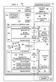
- Composite structure 100 is configured for use in an object, such as, for example, object 102.
- object 102 may take a number of different forms.
- object 102 may be an aerospace vehicle, an unmanned aerial vehicle (UAV), a helicopter, a satellite, a space shuttle, a watercraft, a train, a land vehicle, an automobile, a building, an electromechanical device, armor, or some other suitable type of object.
- UAV unmanned aerial vehicle
- composite structure 100 may be a skin panel for the aerospace vehicle.
- composite structure 100 comprises composite material 104.
- Composite material 104 takes the form of one or more composite layers, such as composite layer 106.
- composite layer 106 is the only layer of composite material 104 in composite material 104.
- composite layer 106 may be one composite layer in a plurality of composite layers, such as plurality of composite layers 108.
- a "plurality of" means two or more.
- plurality of composite layers 108 means two or more composite layers.
- a composite layer may also be referred to as a composite ply.
- Plurality of composite layers 108 may include two, three, four, 10, 20, 50, 100, or some other number of composite layers, depending on the implementation.
- composite layer 106 comprises matrix 110 and reinforcement 112.
- Reinforcement 112 is located within matrix 110 to form composite layer 106.
- matrix 110 is a monolithic material into which reinforcement 112 is embedded in these illustrative examples.
- matrix 110 is substantially continuous. In other words, a path may be present from any point in matrix 110 to any other point in matrix 110.
- Matrix 110 provides support for reinforcement 112.
- Matrix 110 is sometimes referred to as a binder for reinforcement 112.
- matrix 110 comprises substantially nonconductive material 113.
- substantially nonconductive material 113 may comprise any number of materials that are substantially nonconductive. In particular, substantially nonconductive material 113 may not have a desired level of conductivity. Further, substantially nonconductive material 113 may be selected to support reinforcement 112.
- matrix 110 may comprise at least one of a polymer, a plastic, a ceramic material, and some other suitable type of material.
- matrix 110 may comprise one or more polymers selected from at least one of, for example, without limitation, a resin, polyester, vinyl ester, epoxy, phenolic, polyimide, polyamide, a polyether ether ketone (PEEK), polypropylene, a polyester thermosetting plastic, and some other suitable type of polymer material that is substantially nonconductive.
- the phrase "at least one of”, when used with a list of items, means different combinations of one or more of the listed items may be used and only one of each item in the list may be needed.
- “at least one of item A, item B, and item C” may include, without limitation, item A or item A and item B. This example also may include item A, item B, and item C, or item B and item C.
- "at least one of” may be, for example, without limitation, two of item A, one of item B, and 10 of item C; four of item B and seven of item C; and other suitable combinations.
- Reinforcement 112 comprises one or more materials embedded in matrix 110. Reinforcement 112 is configured to provide structural support and strength for composite layer 106. In some illustrative examples, reinforcement 112 is used to introduce desirable properties into composite layer 106. For example, reinforcement 112 may be used to change the physical properties of composite layer 106. These physical properties may include, for example, without limitation, electrical conductivity, wear resistance, a friction coefficient, thermal conductivity, and other suitable physical properties.
- reinforcement 112 is comprised of a number of materials selected from at least one of carbon, glass, silicon carbide, boron, a metallic material, a ceramic material, a metal alloy, a synthetic material, a para-aramid synthetic material, and some other suitable type of material. These materials may take the form of at least one of fibers, flakes, particles, and fillers within reinforcement 112. Depending on the arrangement of these fibers, flakes, particles, and/or fillers in reinforcement 112, reinforcement 112 may be continuous or discontinuous.
- reinforcement 112 comprises conductive material 114.
- Conductive material 114 may be any material configured to conduct an electrical current.
- Conductive material 114 may be carbon in these illustrative examples.
- conductive material 114 may comprise a number of other conductive materials in addition to and/or in place of carbon.
- reinforcement 112 may comprise other materials in addition to conductive material 114.
- composite structure 100 may be a carbon fiber reinforced plastic (CFRP).
- CFRP carbon fiber reinforced plastic
- Reinforcement 112 in each composite layer in the carbon fiber reinforced plastic comprises carbon fibers, while matrix 110 comprises a plastic material.
- composite layer 106 has first surface 116 and second surface 118.
- First portion 120 of reinforcement 112 may be exposed at first surface 116.
- second portion 121 of reinforcement 112 may be exposed at second surface 118.
- a portion of reinforcement 112 is "exposed" when that portion is in contact with the environment around reinforcement 112. For example, when first portion 120 of reinforcement 112 is exposed at first surface 116, some other component may come into contact with first portion 120 of reinforcement 112 at first surface 116.
- reinforcement 112 comprises plurality of fibers 132.
- first portion 120 and second portion 121 of plurality of fibers 132 may each include a group of fibers in plurality of fibers 132. This group of fibers may include fibrils.
- a fiber in plurality of fibers 132 that is exposed at first surface 116 may also be exposed at second surface 118.
- First portion 120 and/or second portion 121 of reinforcement 112 may be exposed at first surface 116 and/or second surface 118, respectively, using a number of different processes.
- a mechanical process, a chemical process, a laser surface ablation process, an etching process, a threading process, a stitching process, an abrasion process, a sanding process, a raking process, and/or some other suitable type of process may be used to expose first portion 120 of reinforcement 112 at first surface 116 and/or second portion 121 of reinforcement 112 at second surface 118.
- first portion 120 of plurality of fibers 132 is exposed at first surface 116 of composite layer 106 by mechanically wearing away a portion of first surface 116 to expose a portion of plurality of fibers 132 near first surface 116.
- the portion of first surface 116 that is worn away may be a portion of matrix 110 at first surface 116.
- First surface 116 may be mechanically worn away using, for example, abrasion, mechanical raking, or some other suitable type of process for wearing away and/or roughening a surface.
- first portion 120 is exposed at first surface 116 by applying a chemical to first surface 116 of composite layer 106.
- the chemical may chemically remove or dissolve away a portion of first surface 116 to expose first portion 120 of reinforcement 112.
- this chemical process may chemically remove or dissolve away a portion of matrix 110 at first surface 116 to expose first portion 120 of reinforcement 112.
- a laser is used to ablate or remove a portion of first surface 116 to expose first portion 120 of reinforcement 112.
- one or more portions of first surface 116 are etched away to expose first portion 120 of reinforcement 112.
- a group of fibers in plurality of fibers 132 for reinforcement 112 is threaded through matrix 110 such that a first portion of the group of fibers is exposed at first surface 116 while a second portion of the group of fibers remains substantially embedded in matrix 110 in composite layer 106.
- the different processes described for exposing first portion 120 of reinforcement 112 at first surface 116 of composite layer 106 may be implemented in a similar manner to expose second portion 121 of reinforcement 112 at second surface 118 of composite layer 106.
- First portion 120 of reinforcement 112 exposed at first surface 116 increases electrical conductivity 122 of composite layer 106 in a direction substantially perpendicular to composite layer 106. Further, second portion 121 of reinforcement 112 exposed at second surface 118 of composite layer 106 increases electrical conductivity 122 of composite layer 106 in the direction substantially perpendicular to composite layer 106.
- Electrical conductivity 122 is a measure of the ability of composite layer 106 to conduct an electrical current. Electrical conductivity 122 of composite layer 106 may be increased at first surface 116 and second surface 118 of composite layer 106 with respect to electrical currents 124 that may flow into and/or out of composite layer 106 at first surface 116 and second surface 118.
- Electrical currents 124 may flow into composite layer 106 from any direction relative to composite layer 106.
- Conductive material 114 of reinforcement 112 allows electrical currents 124 that flow into composite layer 106 from any direction relative to composite layer 106 to be conducted within composite layer 106. Further, electrical currents 124 may flow out of composite layer 106 in any direction relative to composite layer 106.
- first portion 120 of reinforcement 112 may be exposed at a selected portion of first surface 116.
- the portion of first surface 116 at which first portion 120 of reinforcement 112 is exposed may be selected to increase electrical conductivity 122 of composite layer 106 in the direction substantially perpendicular to composite layer 106 at this selected portion of first surface 116 and not at other portions of first surface 116.
- first surface 116 and second surface 118 at which reinforcement 112 is exposed may comprise one portion of each of these surfaces or discontinuous portions of each of these surfaces. In some cases, the selected portion for at least one of first surface 116 and second surface 118 may form a pattern on the surface.
- not all of the composite layers in plurality of composite layers 108 may have reinforcement exposed at both surfaces of the composite layers. In some cases, only a portion of the composite layers in plurality of composite layers 108 has reinforcement exposed at both surfaces. Further, in other examples, a portion of the composite layers in plurality of composite layers 108 has reinforcement exposed at only one surface.
- Any reinforcement exposed at the surface of a composite layer in plurality of composite layers 108 may increase the electrical conductivity of composite laminate 107 in the direction substantially perpendicular to composite laminate 107. Further, depending on the type and/or configuration of the reinforcement in each of plurality of composite layers 108, an increased electrical conductivity of composite laminate 107 in the direction substantially perpendicular to composite laminate 107 may increase the electrical conductivity of composite laminate 107 in any number of other directions with respect to composite laminate 107.
- second portion 146 of second reinforcement 138 may be exposed at second surface 148 of second composite layer 134 such that second electrical conductivity 144 of second composite layer 134 is increased in the direction substantially perpendicular to second composite layer 134.
- first portion 140 and/or second portion 146 of second reinforcement 138 may be exposed at first surface 142 and/or second surface 148, respectively, using any of the processes described above for exposing first portion 120 and second portion 121 of reinforcement 112.
- second composite layer 134 may be positioned relative to composite layer 106.
- second composite layer 134 may be laid up over composite layer 106.
- first portion 120 of reinforcement 112 may contact second portion 146 of second reinforcement 138 at interface 145 between first surface 116 of composite layer 106 and second surface 148 of second composite layer 134.
- electromagnetic event 152 occurs above first surface 142 of second composite layer 134.
- lightning contacts first surface 142 of second composite layer 134.
- lightning contacts first portion 140 of second reinforcement 138 when lightning contacts first surface 142. This lightning strike generates number of electrical currents 150 that are conducted into second composite layer 134.
- first portion 140 and second portion 146 of second reinforcement 138 in second composite layer 134 and first portion 120 and second portion 121 of reinforcement 112 in composite layer 106 may provide conductive pathways for number of electrical currents 150. These conductive pathways provide desired level of electrical conductivity 135 for composite structure 100. Desired level of electrical conductivity 135 may be a higher electrical conductivity in the direction substantially perpendicular to composite structure 100 as compared to currently available composite structures.
- additional conductive material may be applied between composite layers in plurality of composite layers 108.
- This additional conductive material may be used to increase the electrical conductivity of composite structure 100 in the direction substantially parallel to z-axis 126.
- the conductive material applied between the composite layers may include, for example, without limitation, metal particles, chopped carbon fibers, carbon flakes, carbon particles, and/or other suitable types of conductive material.
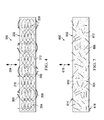
- composite layer 200 is an example of one implementation for composite layer 106 in Figure 1 .
- composite layer 200 comprises matrix 202 and reinforcement 204.
- Reinforcement 204 comprises plurality of fibers 206.
- plurality of fibers 206 may be arranged in the form of mesh 208.
- composite layer 600 comprises matrix 602 and reinforcement 604.
- Reinforcement 604 comprises plurality of fibers 606.
- plurality of fibers 606 is not arranged in a mesh, such as mesh 208 in Figures 2-4 . Instead, plurality of fibers 606 may have a random arrangement within reinforcement 604.
- Each composite layer in plurality of composite layers 802 may be implemented using composite layer 200 from Figure 3 .
- conductive pathways may be formed by contact between the exposed portions of reinforcement at the surfaces of the different composite layers in composite structure 800.
- the process begins by embedding a reinforcement in a matrix to form the composite layer (operation 1100).
- the reinforcement comprises a conductive material.
- the conductive material may be carbon in the form of a plurality of fibers.
- embedding the reinforcement in the matrix causes the reinforcement to be located within the matrix.
- the reinforcement when the reinforcement is embedded in the matrix, no portion of the reinforcement is exposed at any of the surfaces of the composite layer.
- the reinforcement may be embedded in the matrix in a number of different ways.
- the reinforcement may be embedded in the matrix using a resin bath process, a chemical vapor deposition process, a vacuum deposition process, a chemical solution deposition process, a chemical bath deposition process, or some other suitable type of process for embedding the reinforcement within the matrix.
- operation 1102 The process then exposes a portion of the reinforcement at a surface of the composite layer to increase electrical conductivity of the composite layer in a direction substantially perpendicular to the composite layer (operation 1102), with the process terminating thereafter.
- operation 1102 may be performed a first time for a first surface of the composite layer and a second time for a second surface of the composite layer.
- operation 1102 may be performed by removing a portion of the surface of the composite layer to expose the portion of the reinforcement using a laser ablation process. In some cases, operation 1102 may be performed by threading a group of fibers in a plurality of fibers that form the reinforcement through the composite layer such that a first portion of the group of fibers is exposed at the surface of the composite layer and a second portion of the group of fibers remains substantially embedded in the matrix in the composite layer.
- the process begins by operating an object comprising a composite structure in which an electromagnetic event that occurs during operation of the object induces electrical energy in the composite structure (operation 1200).
- the composite structure may be, for example, composite structure 100 in Figure 1 .
- This composite structure may be implemented in the form of, for example, composite structure 800 in Figure 8 .
- the electromagnetic event may be, for example, a lightning strike, a short circuit, an overloaded circuit, or some other suitable type of event configured to generate electrical energy at a surface of the composite structure.
- the electrical energy may take the form of a number of electrical currents and/or electromagnetic forces.
- the function or functions noted in the blocks may occur out of the order noted in the figures.
- two blocks shown in succession may be executed substantially concurrently, or the blocks may sometimes be performed in the reverse order, depending upon the functionality involved.
- other blocks may be added in addition to the illustrated blocks in a flowchart or block diagram.
- Apparatuses and methods embodied herein may be employed during at least one of the stages of aircraft manufacturing and service method 1300 in Figure 13 .
- composite structure 100 from Figure 1 may be designed, manufactured, and implemented in aircraft 1400 in Figure 14 during at least one of specification and design 1302, material procurement 1304, component and subassembly manufacturing 1306, system integration 1308, in service 1312, and/or maintenance and service 1314.
- composite structure 100 in Figure 1 may be used to implement a plurality of skin panels for aircraft 1400 in Figure 14 .
- components or subassemblies produced in component and subassembly manufacturing 1306 in Figure 13 may be fabricated or manufactured in a manner similar to components or subassemblies produced while aircraft 1400 is in service 1312 in Figure 13 .
- a composite structure 100 including a matrix 110 including a substantially nonconductive material 133; and a reinforcement 112 including a conductive material 114, wherein the reinforcement 112 is located within the matrix 110 to form a composite layer in the composite structure in which a portion of the reinforcement 112 is exposed at a surface of the composite layer 106 such that electrical conductivity 122 of the composite layer 106 is increased in a direction substantially perpendicular to the composite layer 106.
- the composite layer 106 is one composite layer 106 in a plurality of composite layers 108 that form the composite structure 100 in which portions of reinforcements for composite layers 108 in the plurality of composite layers 108 are exposed at surfaces of the composite layers in the plurality of composite layers 108 to provide a desired level of electrical conductivity 135 for the plurality of composite layers 108 in a direction substantially parallel to a z-axis 126 for the plurality of composite layers 108.
- an electromagnetic event 152 that occurs in an environment around the plurality of composite layers 108 induces electrical energy 149 in the plurality of composite layers 108 and wherein the plurality of composite layers 108 is configured to conduct the electrical energy 149 between the composite layers in the plurality of composite layers 108 in the direction substantially parallel to the z-axis for the plurality of composite layers 108.
- the composite structure 100 includes the plurality of composite layers 108 is a carbon fiber reinforced plastic configured for use as a skin panel for an aerospace vehicle in which the carbon fiber reinforced plastic has the desired level of electrical conductivity in the direction substantially parallel to the z-axis for the carbon fiber reinforced plastic.
- the portion of the reinforcement 112 embedded in the matrix 110 is exposed at the surface of the composite layer 106 using at least one of a mechanical process, a chemical process, a laser surface ablation process, an etching process, a threading process, a stitching process, an abrasion process, a sanding process, and a raking process.
- a composite structure 100 including: a plurality of composite layers 108 in which a composite layer 106 in the plurality of composite layers 108 includes: a matrix 110 including a substantially nonconductive material 113; and a reinforcement 112 including a conductive material 114 and located within the matrix 110 in which a portion of the reinforcement 112 is exposed at a surface of the composite layer 106 such that electrical conductivity 122 of the composite layer 106 is increased in a direction substantially perpendicular to the composite layer, wherein the portion of the reinforcement 112 exposed at the surface of the composite layer 106 electrically connects the composite layer 106 to another composite layer 106 in the plurality of composite layers 108 such that the composite structure 100 has a desired level of electrical conductivity 135 in a direction substantially parallel to a z-axis 126 for the composite structure 100.
- the composite structure 100 includes the plurality of composite layers 108 is carbon fiber reinforced plastic configured for use as a skin panel for an aerospace vehicle.
- a method for conducting electrical energy 149 using a composite structure 100 includes: operating an object 102 including the composite structure 100 in which the electrical energy 149 is induced in the composite structure 100 in response to an electromagnetic event 152 that occurs during operation of the object 102, wherein the composite structure 100 includes a plurality of composite layers 108 in which a composite layer 106 in the plurality of composite layers 108 includes: a matrix 110 including a substantially nonconductive material 113; and a reinforcement 112 including a conductive material 114 and located within the matrix 110 in which a portion of the reinforcement 112 is exposed at a surface of the composite layer 106; and conducting the electrical energy 149 induced in the composite structure 100 in response to the electromagnetic event 152 within the composite structure 100 using the portion of the reinforcement 112 exposed at the surface of the composite layer 106 in the plurality of composite layers 108 such that electrical conductivity 122 of the composite structure 100 is increased in a direction substantially parallel to a z-axis 126 for the composite structure 100.
- the step of conducting the electrical energy 149 induced in the composite structure 100 in response to the electromagnetic event 152 within the composite structure 100 using the portion of the reinforcement 112 exposed at the surface of the composite layer 106 in the plurality of composite layers 108 such that the electrical conductivity 122 of the composite structure 100 is increased in the direction substantially parallel to the z-axis 126 for the composite structure 100 comprises: conducting the electrical energy 149 induced in the composite structure 100 in response to the electromagnetic event 152 within the composite structure 100 such that the electrical conductivity 122 of the composite structure 100 is increased in the direction substantially parallel to the z-axis 126 for the composite structure 100, wherein the portion of the reinforcement 112 exposed at the surface of the composite layer 106 electrically connects the composite layer 106 to another composite layer 106 in the plurality of composite layers 108 such that the composite structure 100 has a desired level of electrical conductivity 135 in the direction substantially parallel to the z-axis 126 for the composite structure 100.
- a method for forming a composite layer 106 includes: embedding a reinforcement 112 in a matrix 110 to form the composite layer 106, wherein the matrix 110 includes a substantially nonconductive material 113 and wherein the reinforcement 112 includes a conductive material 114; and exposing a portion of the reinforcement 112 at a selected portion of a surface of the composite layer 106 such that electrical conductivity 122 of the composite layer 106 is increased in a direction substantially perpendicular to the composite layer 106.
- the step of exposing the portion of the reinforcement 112 at the selected portion of the surface of the composite layer 106 includes: roughening the surface of the composite layer 106 to remove a portion of the matrix 110 at the surface of the composite layer 106 to expose the portion of the reinforcement 112 substantially underneath the portion of the matrix at the surface of the composite layer 106.
- the step of exposing the portion of the reinforcement 112 at the selected portion of the surface of the composite layer 106 includes: applying a chemical to the surface of the composite layer to chemically remove a portion of the matrix at the surface of the composite layer 106 to expose the portion of the reinforcement 112.
- the step of exposing the portion of the reinforcement 112 at the selected portion of the surface of the composite layer 106 includes: removing a portion of the matrix 110 at the surface of the composite layer 106 using a laser surface ablation process to expose the portion of the reinforcement 112.
- the step of exposing the portion of the reinforcement 112 at the selected portion of the surface of the composite layer 106 includes: threading a group of fibers in a plurality of fibers 132 that form the reinforcement 112 through the composite layer 106 such that a first portion 120 of the group of fibers is exposed at the surface of the composite layer 106 and a second portion 121 of the group of fibers remains substantially embedded in the matrix 110 in the composite layer 106.
- an apparatus comprises a matrix and a reinforcement.
- the matrix comprises a nonconductive material.
- the reinforcement comprises a conductive material.
- the reinforcement is located within the matrix to form a composite layer. A portion of the reinforcement is exposed at a surface of the composite layer such that electrical conductivity of the composite layer is increased in a direction substantially perpendicular to the composite layer.
- this composite layer may be one composite layer in a plurality of composite layers for a composite structure.
- Each of the plurality of composite layers for the composite structure may be implemented in a manner similar to the composite layer described above.
- a first portion of the reinforcement is exposed at a first surface of each composite layer to increase electrical conductivity of each composite layer at the first surface of each composite layer.
- a second portion of the reinforcement is exposed at a second surface of each composite layer to increase the electrical conductivity of each composite layer at the second surface of each composite layer.
- the first portion and the second portion of the reinforcement in each composite layer in the plurality of composite layers is configured to electrically connect the plurality of composite layers to each other such that the composite structure has a desired level of electrical conductivity in a direction substantially perpendicular to the composite structure.
Landscapes
- Chemical & Material Sciences (AREA)
- Engineering & Computer Science (AREA)
- Composite Materials (AREA)
- Mechanical Engineering (AREA)
- Laminated Bodies (AREA)
- Moulding By Coating Moulds (AREA)
Applications Claiming Priority (1)
| Application Number | Priority Date | Filing Date | Title |
|---|---|---|---|
| US13/400,334 US10046528B2 (en) | 2012-02-20 | 2012-02-20 | Composite layers with exposed reinforcement |
Publications (2)
| Publication Number | Publication Date |
|---|---|
| EP2628589A1 true EP2628589A1 (fr) | 2013-08-21 |
| EP2628589B1 EP2628589B1 (fr) | 2018-05-02 |
Family
ID=47598682
Family Applications (1)
| Application Number | Title | Priority Date | Filing Date |
|---|---|---|---|
| EP13151015.8A Active EP2628589B1 (fr) | 2012-02-20 | 2013-01-11 | Couches de composite avec renfort exposé |
Country Status (5)
| Country | Link |
|---|---|
| US (1) | US10046528B2 (fr) |
| EP (1) | EP2628589B1 (fr) |
| JP (1) | JP6120605B2 (fr) |
| CN (1) | CN103252966B (fr) |
| ES (1) | ES2682099T3 (fr) |
Cited By (1)
| Publication number | Priority date | Publication date | Assignee | Title |
|---|---|---|---|---|
| DE102014113279A1 (de) * | 2014-09-15 | 2016-03-17 | Airbus Operations Gmbh | Faserverbundbauteil mit einem elektrisch leitfähigen Fasermaterial zur Verstärkung sowie Vorrichtung zur Herstellung desselben |
Families Citing this family (3)
| Publication number | Priority date | Publication date | Assignee | Title |
|---|---|---|---|---|
| US10102939B2 (en) * | 2013-01-28 | 2018-10-16 | The Boeing Company | Conductive fiber reinforced polymer composition |
| US10391751B2 (en) * | 2016-04-20 | 2019-08-27 | The Boeing Company | Spatial reference film in core-stiffened composite |
| US20220274369A1 (en) * | 2021-03-01 | 2022-09-01 | Government Of The United States, As Represented By The Secretary Of The Air Force | Prepregs and cured composites having improved surfaces and processes of making and methods of using same |
Citations (4)
| Publication number | Priority date | Publication date | Assignee | Title |
|---|---|---|---|---|
| US4681497A (en) * | 1985-05-29 | 1987-07-21 | Microdot Inc. | Encapsulated fastener |
| US4746389A (en) * | 1987-08-04 | 1988-05-24 | United Technologies Corporation | Method for producing a clean, highly conductive surface for mating composite articles |
| US4820376A (en) * | 1987-11-05 | 1989-04-11 | American Telephone And Telegraph Company At&T Bell Laboratories | Fabrication of CPI layers |
| US6624383B1 (en) * | 2000-08-30 | 2003-09-23 | Parker-Hannifin Corporation | Using laser etching to improve surface contact resistance of conductive fiber filler polymer composites |
Family Cites Families (11)
| Publication number | Priority date | Publication date | Assignee | Title |
|---|---|---|---|---|
| US2359090A (en) | 1943-04-16 | 1944-09-26 | American Steel & Wire Co | Composite electrical conductor |
| CA2161547A1 (fr) * | 1993-04-30 | 1994-11-10 | Joseph Santin Boyce | Joint renforce pour structures en materiau composite et procede associe |
| US7935415B1 (en) | 2002-04-17 | 2011-05-03 | Conductive Composites Company, L.L.C. | Electrically conductive composite material |
| DK176564B1 (da) * | 2004-12-29 | 2008-09-01 | Lm Glasfiber As | Fiberforstærket samling |
| WO2006128741A1 (fr) | 2005-06-02 | 2006-12-07 | Nv Bekaert Sa | Logement de blindage emi polymere dote de fibres conductrices |
| JP2008028258A (ja) * | 2006-07-24 | 2008-02-07 | Nisshinbo Ind Inc | 積層シートおよびその製造方法 |
| JPWO2008111194A1 (ja) | 2007-03-14 | 2010-06-24 | 国立大学法人福島大学 | 導電性複合材料およびその製造方法 |
| US7897249B2 (en) | 2008-10-07 | 2011-03-01 | The Boeing Company | Composite material structure with interlayer electrical conductance |
| CA2786836C (fr) * | 2010-01-14 | 2019-01-22 | Saab Ab | Surface aerodynamique avec proprietes ameliorees |
| GB2478749A (en) * | 2010-03-17 | 2011-09-21 | Hexcel Composites Ltd | Composite materials of reduced electrical resistance |
| DE102011115406A1 (de) * | 2011-10-06 | 2013-04-11 | Airbus Operations Gmbh | Verfahren zum Verbinden von faserverstärkten Zwischenprodukten und Strukturbauteil mit faserverstärkten Zwischenprodukten sowie Verfahren und Vorrichtung zur Herstellung einer Adhäsionsschicht |
-
2012
- 2012-02-20 US US13/400,334 patent/US10046528B2/en active Active
-
2013
- 2013-01-11 EP EP13151015.8A patent/EP2628589B1/fr active Active
- 2013-01-11 ES ES13151015.8T patent/ES2682099T3/es active Active
- 2013-02-20 JP JP2013031094A patent/JP6120605B2/ja active Active
- 2013-02-20 CN CN201310054185.XA patent/CN103252966B/zh active Active
Patent Citations (4)
| Publication number | Priority date | Publication date | Assignee | Title |
|---|---|---|---|---|
| US4681497A (en) * | 1985-05-29 | 1987-07-21 | Microdot Inc. | Encapsulated fastener |
| US4746389A (en) * | 1987-08-04 | 1988-05-24 | United Technologies Corporation | Method for producing a clean, highly conductive surface for mating composite articles |
| US4820376A (en) * | 1987-11-05 | 1989-04-11 | American Telephone And Telegraph Company At&T Bell Laboratories | Fabrication of CPI layers |
| US6624383B1 (en) * | 2000-08-30 | 2003-09-23 | Parker-Hannifin Corporation | Using laser etching to improve surface contact resistance of conductive fiber filler polymer composites |
Cited By (1)
| Publication number | Priority date | Publication date | Assignee | Title |
|---|---|---|---|---|
| DE102014113279A1 (de) * | 2014-09-15 | 2016-03-17 | Airbus Operations Gmbh | Faserverbundbauteil mit einem elektrisch leitfähigen Fasermaterial zur Verstärkung sowie Vorrichtung zur Herstellung desselben |
Also Published As
| Publication number | Publication date |
|---|---|
| EP2628589B1 (fr) | 2018-05-02 |
| JP6120605B2 (ja) | 2017-04-26 |
| JP2013173361A (ja) | 2013-09-05 |
| ES2682099T3 (es) | 2018-09-18 |
| CN103252966B (zh) | 2018-06-22 |
| US20130213685A1 (en) | 2013-08-22 |
| US10046528B2 (en) | 2018-08-14 |
| CN103252966A (zh) | 2013-08-21 |
Similar Documents
| Publication | Publication Date | Title |
|---|---|---|
| US8146861B2 (en) | Component with carbon nanotubes | |
| CN106560399B (zh) | 用于从复合非金属结构中的蒙皮紧固件转移雷电电流的方法 | |
| US9253823B2 (en) | Metal matrix composite used as a heating element | |
| US10368401B2 (en) | Multi-functional composite structures | |
| EP2285562B1 (fr) | Système et procédé de fabrication d'un matériau de protection contre le foudroiement intégré | |
| US7883050B2 (en) | Composites with integrated multi-functional circuits | |
| US7829796B2 (en) | Circuit joining assembly materials for multi-layer lightning protection systems on composite aircraft | |
| EP3083231B1 (fr) | Structure composite | |
| EP2401195B1 (fr) | Distribution de puissance dans des systèmes à structure composite | |
| EP2540625A2 (fr) | Structure électriquement conductrice | |
| EP2628589B1 (fr) | Couches de composite avec renfort exposé | |
| EP2987562B1 (fr) | Procédés et appareil pour une utilisation dans la formation d'un système de protection contre la foudre |
Legal Events
| Date | Code | Title | Description |
|---|---|---|---|
| PUAI | Public reference made under article 153(3) epc to a published international application that has entered the european phase |
Free format text: ORIGINAL CODE: 0009012 |
|
| AK | Designated contracting states |
Kind code of ref document: A1 Designated state(s): AL AT BE BG CH CY CZ DE DK EE ES FI FR GB GR HR HU IE IS IT LI LT LU LV MC MK MT NL NO PL PT RO RS SE SI SK SM TR |
|
| AX | Request for extension of the european patent |
Extension state: BA ME |
|
| 17P | Request for examination filed |
Effective date: 20140125 |
|
| RBV | Designated contracting states (corrected) |
Designated state(s): AL AT BE BG CH CY CZ DE DK EE ES FI FR GB GR HR HU IE IS IT LI LT LU LV MC MK MT NL NO PL PT RO RS SE SI SK SM TR |
|
| 17Q | First examination report despatched |
Effective date: 20151216 |
|
| GRAP | Despatch of communication of intention to grant a patent |
Free format text: ORIGINAL CODE: EPIDOSNIGR1 |
|
| STAA | Information on the status of an ep patent application or granted ep patent |
Free format text: STATUS: GRANT OF PATENT IS INTENDED |
|
| RIC1 | Information provided on ipc code assigned before grant |
Ipc: H05K 9/00 20060101ALI20170818BHEP Ipc: B29C 70/54 20060101ALN20170818BHEP Ipc: B29C 70/64 20060101AFI20170818BHEP Ipc: B29C 70/88 20060101ALI20170818BHEP |
|
| INTG | Intention to grant announced |
Effective date: 20170922 |
|
| GRAJ | Information related to disapproval of communication of intention to grant by the applicant or resumption of examination proceedings by the epo deleted |
Free format text: ORIGINAL CODE: EPIDOSDIGR1 |
|
| STAA | Information on the status of an ep patent application or granted ep patent |
Free format text: STATUS: EXAMINATION IS IN PROGRESS |
|
| GRAP | Despatch of communication of intention to grant a patent |
Free format text: ORIGINAL CODE: EPIDOSNIGR1 |
|
| STAA | Information on the status of an ep patent application or granted ep patent |
Free format text: STATUS: GRANT OF PATENT IS INTENDED |
|
| INTC | Intention to grant announced (deleted) | ||
| RIC1 | Information provided on ipc code assigned before grant |
Ipc: B29C 70/88 20060101ALI20171102BHEP Ipc: H05K 9/00 20060101ALI20171102BHEP Ipc: B29C 70/54 20060101ALN20171102BHEP Ipc: B29C 70/64 20060101AFI20171102BHEP |
|
| INTG | Intention to grant announced |
Effective date: 20171120 |
|
| GRAS | Grant fee paid |
Free format text: ORIGINAL CODE: EPIDOSNIGR3 |
|
| GRAA | (expected) grant |
Free format text: ORIGINAL CODE: 0009210 |
|
| STAA | Information on the status of an ep patent application or granted ep patent |
Free format text: STATUS: THE PATENT HAS BEEN GRANTED |
|
| AK | Designated contracting states |
Kind code of ref document: B1 Designated state(s): AL AT BE BG CH CY CZ DE DK EE ES FI FR GB GR HR HU IE IS IT LI LT LU LV MC MK MT NL NO PL PT RO RS SE SI SK SM TR |
|
| REG | Reference to a national code |
Ref country code: GB Ref legal event code: FG4D |
|
| REG | Reference to a national code |
Ref country code: CH Ref legal event code: EP Ref country code: AT Ref legal event code: REF Ref document number: 994740 Country of ref document: AT Kind code of ref document: T Effective date: 20180515 |
|
| REG | Reference to a national code |
Ref country code: DE Ref legal event code: R096 Ref document number: 602013036746 Country of ref document: DE Ref country code: IE Ref legal event code: FG4D |
|
| REG | Reference to a national code |
Ref country code: NL Ref legal event code: MP Effective date: 20180502 |
|
| REG | Reference to a national code |
Ref country code: ES Ref legal event code: FG2A Ref document number: 2682099 Country of ref document: ES Kind code of ref document: T3 Effective date: 20180918 |
|
| REG | Reference to a national code |
Ref country code: LT Ref legal event code: MG4D |
|
| PG25 | Lapsed in a contracting state [announced via postgrant information from national office to epo] |
Ref country code: FI Free format text: LAPSE BECAUSE OF FAILURE TO SUBMIT A TRANSLATION OF THE DESCRIPTION OR TO PAY THE FEE WITHIN THE PRESCRIBED TIME-LIMIT Effective date: 20180502 Ref country code: NO Free format text: LAPSE BECAUSE OF FAILURE TO SUBMIT A TRANSLATION OF THE DESCRIPTION OR TO PAY THE FEE WITHIN THE PRESCRIBED TIME-LIMIT Effective date: 20180802 Ref country code: BG Free format text: LAPSE BECAUSE OF FAILURE TO SUBMIT A TRANSLATION OF THE DESCRIPTION OR TO PAY THE FEE WITHIN THE PRESCRIBED TIME-LIMIT Effective date: 20180802 Ref country code: SE Free format text: LAPSE BECAUSE OF FAILURE TO SUBMIT A TRANSLATION OF THE DESCRIPTION OR TO PAY THE FEE WITHIN THE PRESCRIBED TIME-LIMIT Effective date: 20180502 Ref country code: LT Free format text: LAPSE BECAUSE OF FAILURE TO SUBMIT A TRANSLATION OF THE DESCRIPTION OR TO PAY THE FEE WITHIN THE PRESCRIBED TIME-LIMIT Effective date: 20180502 |
|
| PG25 | Lapsed in a contracting state [announced via postgrant information from national office to epo] |
Ref country code: LV Free format text: LAPSE BECAUSE OF FAILURE TO SUBMIT A TRANSLATION OF THE DESCRIPTION OR TO PAY THE FEE WITHIN THE PRESCRIBED TIME-LIMIT Effective date: 20180502 Ref country code: NL Free format text: LAPSE BECAUSE OF FAILURE TO SUBMIT A TRANSLATION OF THE DESCRIPTION OR TO PAY THE FEE WITHIN THE PRESCRIBED TIME-LIMIT Effective date: 20180502 Ref country code: GR Free format text: LAPSE BECAUSE OF FAILURE TO SUBMIT A TRANSLATION OF THE DESCRIPTION OR TO PAY THE FEE WITHIN THE PRESCRIBED TIME-LIMIT Effective date: 20180803 Ref country code: HR Free format text: LAPSE BECAUSE OF FAILURE TO SUBMIT A TRANSLATION OF THE DESCRIPTION OR TO PAY THE FEE WITHIN THE PRESCRIBED TIME-LIMIT Effective date: 20180502 Ref country code: RS Free format text: LAPSE BECAUSE OF FAILURE TO SUBMIT A TRANSLATION OF THE DESCRIPTION OR TO PAY THE FEE WITHIN THE PRESCRIBED TIME-LIMIT Effective date: 20180502 |
|
| REG | Reference to a national code |
Ref country code: AT Ref legal event code: MK05 Ref document number: 994740 Country of ref document: AT Kind code of ref document: T Effective date: 20180502 |
|
| PG25 | Lapsed in a contracting state [announced via postgrant information from national office to epo] |
Ref country code: PL Free format text: LAPSE BECAUSE OF FAILURE TO SUBMIT A TRANSLATION OF THE DESCRIPTION OR TO PAY THE FEE WITHIN THE PRESCRIBED TIME-LIMIT Effective date: 20180502 Ref country code: DK Free format text: LAPSE BECAUSE OF FAILURE TO SUBMIT A TRANSLATION OF THE DESCRIPTION OR TO PAY THE FEE WITHIN THE PRESCRIBED TIME-LIMIT Effective date: 20180502 Ref country code: AT Free format text: LAPSE BECAUSE OF FAILURE TO SUBMIT A TRANSLATION OF THE DESCRIPTION OR TO PAY THE FEE WITHIN THE PRESCRIBED TIME-LIMIT Effective date: 20180502 Ref country code: EE Free format text: LAPSE BECAUSE OF FAILURE TO SUBMIT A TRANSLATION OF THE DESCRIPTION OR TO PAY THE FEE WITHIN THE PRESCRIBED TIME-LIMIT Effective date: 20180502 Ref country code: RO Free format text: LAPSE BECAUSE OF FAILURE TO SUBMIT A TRANSLATION OF THE DESCRIPTION OR TO PAY THE FEE WITHIN THE PRESCRIBED TIME-LIMIT Effective date: 20180502 Ref country code: CZ Free format text: LAPSE BECAUSE OF FAILURE TO SUBMIT A TRANSLATION OF THE DESCRIPTION OR TO PAY THE FEE WITHIN THE PRESCRIBED TIME-LIMIT Effective date: 20180502 Ref country code: SK Free format text: LAPSE BECAUSE OF FAILURE TO SUBMIT A TRANSLATION OF THE DESCRIPTION OR TO PAY THE FEE WITHIN THE PRESCRIBED TIME-LIMIT Effective date: 20180502 |
|
| REG | Reference to a national code |
Ref country code: DE Ref legal event code: R097 Ref document number: 602013036746 Country of ref document: DE |
|
| PG25 | Lapsed in a contracting state [announced via postgrant information from national office to epo] |
Ref country code: SM Free format text: LAPSE BECAUSE OF FAILURE TO SUBMIT A TRANSLATION OF THE DESCRIPTION OR TO PAY THE FEE WITHIN THE PRESCRIBED TIME-LIMIT Effective date: 20180502 |
|
| PLBE | No opposition filed within time limit |
Free format text: ORIGINAL CODE: 0009261 |
|
| STAA | Information on the status of an ep patent application or granted ep patent |
Free format text: STATUS: NO OPPOSITION FILED WITHIN TIME LIMIT |
|
| 26N | No opposition filed |
Effective date: 20190205 |
|
| PG25 | Lapsed in a contracting state [announced via postgrant information from national office to epo] |
Ref country code: SI Free format text: LAPSE BECAUSE OF FAILURE TO SUBMIT A TRANSLATION OF THE DESCRIPTION OR TO PAY THE FEE WITHIN THE PRESCRIBED TIME-LIMIT Effective date: 20180502 |
|
| PG25 | Lapsed in a contracting state [announced via postgrant information from national office to epo] |
Ref country code: MC Free format text: LAPSE BECAUSE OF FAILURE TO SUBMIT A TRANSLATION OF THE DESCRIPTION OR TO PAY THE FEE WITHIN THE PRESCRIBED TIME-LIMIT Effective date: 20180502 |
|
| REG | Reference to a national code |
Ref country code: CH Ref legal event code: PL |
|
| PG25 | Lapsed in a contracting state [announced via postgrant information from national office to epo] |
Ref country code: LU Free format text: LAPSE BECAUSE OF NON-PAYMENT OF DUE FEES Effective date: 20190111 |
|
| REG | Reference to a national code |
Ref country code: BE Ref legal event code: MM Effective date: 20190131 |
|
| REG | Reference to a national code |
Ref country code: IE Ref legal event code: MM4A |
|
| PG25 | Lapsed in a contracting state [announced via postgrant information from national office to epo] |
Ref country code: AL Free format text: LAPSE BECAUSE OF FAILURE TO SUBMIT A TRANSLATION OF THE DESCRIPTION OR TO PAY THE FEE WITHIN THE PRESCRIBED TIME-LIMIT Effective date: 20180502 Ref country code: BE Free format text: LAPSE BECAUSE OF NON-PAYMENT OF DUE FEES Effective date: 20190131 |
|
| PG25 | Lapsed in a contracting state [announced via postgrant information from national office to epo] |
Ref country code: CH Free format text: LAPSE BECAUSE OF NON-PAYMENT OF DUE FEES Effective date: 20190131 Ref country code: LI Free format text: LAPSE BECAUSE OF NON-PAYMENT OF DUE FEES Effective date: 20190131 |
|
| PG25 | Lapsed in a contracting state [announced via postgrant information from national office to epo] |
Ref country code: IE Free format text: LAPSE BECAUSE OF NON-PAYMENT OF DUE FEES Effective date: 20190111 |
|
| PG25 | Lapsed in a contracting state [announced via postgrant information from national office to epo] |
Ref country code: TR Free format text: LAPSE BECAUSE OF FAILURE TO SUBMIT A TRANSLATION OF THE DESCRIPTION OR TO PAY THE FEE WITHIN THE PRESCRIBED TIME-LIMIT Effective date: 20180502 |
|
| PG25 | Lapsed in a contracting state [announced via postgrant information from national office to epo] |
Ref country code: PT Free format text: LAPSE BECAUSE OF FAILURE TO SUBMIT A TRANSLATION OF THE DESCRIPTION OR TO PAY THE FEE WITHIN THE PRESCRIBED TIME-LIMIT Effective date: 20180903 Ref country code: MT Free format text: LAPSE BECAUSE OF NON-PAYMENT OF DUE FEES Effective date: 20190111 |
|
| PG25 | Lapsed in a contracting state [announced via postgrant information from national office to epo] |
Ref country code: CY Free format text: LAPSE BECAUSE OF FAILURE TO SUBMIT A TRANSLATION OF THE DESCRIPTION OR TO PAY THE FEE WITHIN THE PRESCRIBED TIME-LIMIT Effective date: 20180502 |
|
| PG25 | Lapsed in a contracting state [announced via postgrant information from national office to epo] |
Ref country code: IS Free format text: LAPSE BECAUSE OF FAILURE TO SUBMIT A TRANSLATION OF THE DESCRIPTION OR TO PAY THE FEE WITHIN THE PRESCRIBED TIME-LIMIT Effective date: 20180902 |
|
| PG25 | Lapsed in a contracting state [announced via postgrant information from national office to epo] |
Ref country code: HU Free format text: LAPSE BECAUSE OF FAILURE TO SUBMIT A TRANSLATION OF THE DESCRIPTION OR TO PAY THE FEE WITHIN THE PRESCRIBED TIME-LIMIT; INVALID AB INITIO Effective date: 20130111 |
|
| PG25 | Lapsed in a contracting state [announced via postgrant information from national office to epo] |
Ref country code: MK Free format text: LAPSE BECAUSE OF FAILURE TO SUBMIT A TRANSLATION OF THE DESCRIPTION OR TO PAY THE FEE WITHIN THE PRESCRIBED TIME-LIMIT Effective date: 20180502 |
|
| P01 | Opt-out of the competence of the unified patent court (upc) registered |
Effective date: 20230516 |
|
| PGFP | Annual fee paid to national office [announced via postgrant information from national office to epo] |
Ref country code: DE Payment date: 20250129 Year of fee payment: 13 |
|
| PGFP | Annual fee paid to national office [announced via postgrant information from national office to epo] |
Ref country code: ES Payment date: 20250203 Year of fee payment: 13 |
|
| PGFP | Annual fee paid to national office [announced via postgrant information from national office to epo] |
Ref country code: FR Payment date: 20250127 Year of fee payment: 13 |
|
| PGFP | Annual fee paid to national office [announced via postgrant information from national office to epo] |
Ref country code: IT Payment date: 20250121 Year of fee payment: 13 Ref country code: GB Payment date: 20250127 Year of fee payment: 13 |