EP2628593B1 - Trägereinheit und Bearbeitungsmodul zum Aufbau einer Druckmaschine - Google Patents
Trägereinheit und Bearbeitungsmodul zum Aufbau einer Druckmaschine Download PDFInfo
- Publication number
- EP2628593B1 EP2628593B1 EP13153784.7A EP13153784A EP2628593B1 EP 2628593 B1 EP2628593 B1 EP 2628593B1 EP 13153784 A EP13153784 A EP 13153784A EP 2628593 B1 EP2628593 B1 EP 2628593B1
- Authority
- EP
- European Patent Office
- Prior art keywords
- processing module
- printing
- unit
- longitudinal guide
- carrier unit
- Prior art date
- Legal status (The legal status is an assumption and is not a legal conclusion. Google has not performed a legal analysis and makes no representation as to the accuracy of the status listed.)
- Not-in-force
Links
- 238000007639 printing Methods 0.000 title claims description 71
- 238000003754 machining Methods 0.000 title description 6
- 239000000463 material Substances 0.000 claims description 11
- 238000010276 construction Methods 0.000 claims description 7
- 230000000295 complement effect Effects 0.000 claims description 6
- 238000004049 embossing Methods 0.000 claims description 6
- 239000007787 solid Substances 0.000 claims description 3
- 239000002969 artificial stone Substances 0.000 claims description 2
- 239000010438 granite Substances 0.000 claims description 2
- 239000004575 stone Substances 0.000 claims description 2
- 238000000034 method Methods 0.000 description 30
- 238000007650 screen-printing Methods 0.000 description 7
- 238000001816 cooling Methods 0.000 description 6
- 238000004080 punching Methods 0.000 description 6
- 230000008878 coupling Effects 0.000 description 5
- 238000010168 coupling process Methods 0.000 description 5
- 238000005859 coupling reaction Methods 0.000 description 5
- 238000011161 development Methods 0.000 description 5
- 230000018109 developmental process Effects 0.000 description 5
- 239000007769 metal material Substances 0.000 description 5
- 238000001035 drying Methods 0.000 description 4
- 238000007645 offset printing Methods 0.000 description 4
- 238000007646 gravure printing Methods 0.000 description 3
- 239000000758 substrate Substances 0.000 description 3
- 238000005266 casting Methods 0.000 description 2
- 238000005516 engineering process Methods 0.000 description 2
- 239000011888 foil Substances 0.000 description 2
- 238000004519 manufacturing process Methods 0.000 description 2
- 229910000831 Steel Inorganic materials 0.000 description 1
- RTAQQCXQSZGOHL-UHFFFAOYSA-N Titanium Chemical compound [Ti] RTAQQCXQSZGOHL-UHFFFAOYSA-N 0.000 description 1
- 229910052782 aluminium Inorganic materials 0.000 description 1
- XAGFODPZIPBFFR-UHFFFAOYSA-N aluminium Chemical compound [Al] XAGFODPZIPBFFR-UHFFFAOYSA-N 0.000 description 1
- 230000001419 dependent effect Effects 0.000 description 1
- 238000007641 inkjet printing Methods 0.000 description 1
- 229910052500 inorganic mineral Inorganic materials 0.000 description 1
- 238000003475 lamination Methods 0.000 description 1
- 239000011707 mineral Substances 0.000 description 1
- 210000001331 nose Anatomy 0.000 description 1
- 230000003287 optical effect Effects 0.000 description 1
- 230000000704 physical effect Effects 0.000 description 1
- 229920000642 polymer Polymers 0.000 description 1
- 238000010022 rotary screen printing Methods 0.000 description 1
- 239000010959 steel Substances 0.000 description 1
- 239000010936 titanium Substances 0.000 description 1
- 229910052719 titanium Inorganic materials 0.000 description 1
- 238000009966 trimming Methods 0.000 description 1
Images




Classifications
-
- B—PERFORMING OPERATIONS; TRANSPORTING
- B41—PRINTING; LINING MACHINES; TYPEWRITERS; STAMPS
- B41F—PRINTING MACHINES OR PRESSES
- B41F11/00—Rotary presses or machines having forme cylinders carrying a plurality of printing surfaces, or for performing letterpress, lithographic, or intaglio processes selectively or in combination
-
- B—PERFORMING OPERATIONS; TRANSPORTING
- B41—PRINTING; LINING MACHINES; TYPEWRITERS; STAMPS
- B41F—PRINTING MACHINES OR PRESSES
- B41F13/00—Common details of rotary presses or machines
- B41F13/0024—Frames
-
- B—PERFORMING OPERATIONS; TRANSPORTING
- B41—PRINTING; LINING MACHINES; TYPEWRITERS; STAMPS
- B41F—PRINTING MACHINES OR PRESSES
- B41F19/00—Apparatus or machines for carrying out printing operations combined with other operations
- B41F19/001—Apparatus or machines for carrying out printing operations combined with other operations with means for coating or laminating
-
- B—PERFORMING OPERATIONS; TRANSPORTING
- B41—PRINTING; LINING MACHINES; TYPEWRITERS; STAMPS
- B41F—PRINTING MACHINES OR PRESSES
- B41F19/00—Apparatus or machines for carrying out printing operations combined with other operations
- B41F19/007—Apparatus or machines for carrying out printing operations combined with other operations with selective printing mechanisms, e.g. ink-jet or thermal printers
-
- B—PERFORMING OPERATIONS; TRANSPORTING
- B41—PRINTING; LINING MACHINES; TYPEWRITERS; STAMPS
- B41F—PRINTING MACHINES OR PRESSES
- B41F19/00—Apparatus or machines for carrying out printing operations combined with other operations
- B41F19/008—Apparatus or machines for carrying out printing operations combined with other operations with means for stamping or cutting out
-
- B—PERFORMING OPERATIONS; TRANSPORTING
- B41—PRINTING; LINING MACHINES; TYPEWRITERS; STAMPS
- B41F—PRINTING MACHINES OR PRESSES
- B41F19/00—Apparatus or machines for carrying out printing operations combined with other operations
- B41F19/02—Apparatus or machines for carrying out printing operations combined with other operations with embossing
-
- B—PERFORMING OPERATIONS; TRANSPORTING
- B41—PRINTING; LINING MACHINES; TYPEWRITERS; STAMPS
- B41P—INDEXING SCHEME RELATING TO PRINTING, LINING MACHINES, TYPEWRITERS, AND TO STAMPS
- B41P2217/00—Printing machines of special types or for particular purposes
- B41P2217/10—Printing machines of special types or for particular purposes characterised by their constructional features
- B41P2217/11—Machines with modular units, i.e. with units exchangeable as a whole
Definitions
- the invention relates to a processing module according to the preamble of claim 1 and a carrier unit according to the preamble of claim 6, which together form a printing press according to claim 10.
- printing machines for printing labels and cartons great flexibility or variability is increasingly desired in order to be able to carry out as many different types of printing jobs as possible, in particular by producing special optical effects through the printed image or the printed text.
- printing presses are particularly frequently used, which process a narrow web of a printing material and have a number of connection platforms or interfaces, on each of which a functional unit or a process module for printing can be detachably picked up with a specific printing process.
- a functional unit or a process module for printing can be detachably picked up with a specific printing process.
- one embodiment of such a printing press is in the document US 4,384,522 described.
- the individual functional units can work with mutually different printing methods.
- Multi-printing presses are known in series construction which permit the detachable receipt of a number of functional units or process modules on a number of interconnect platforms.
- the functional units may contain, among other things, printing units or parts of printing units in cassettes or essays which operate according to a letterpress method, a flexographic printing method, a screen printing method, an offset printing method, a gravure printing method or an inkjet printing method.
- functional units processing units
- Such printing machines which can operate on a variety of different printing methods, are also referred to as combination printing machines or hybrid printing machines.
- a printing press in particular label printing machine or sheet-processing offset printing machine, the printing units are housed in a stone-made machine support structure. Different printing units can be used or exchanged and the printing press can be adapted to a particular job.
- a printing press in a modular design is used in the EP 2 042 315 A2 described.
- a plurality of rack modules can be positioned in series, to which the rack modules are aligned.
- the frame modules can be equipped with process modules, wherein the process modules have processing cylinders and web guide rollers.
- Object of the present invention is therefore to provide a printing machine, the structure of which can be changed extremely flexible.
- the carrier unit serves for receiving and arbitrary positioning of processing modules for printing and print finishing for modular construction of a narrow web label printing machine.
- the support unit has a solid cuboid having at least three feet and at least one longitudinal guide, wherein the feet are attached to the underside of the cuboid and wherein the longitudinal guide is attached to the top of the cuboid and extends over the length of the cuboid.
- Such a carrier unit is characterized by a very simple structure, which allows a simple and cost-effective production of the carrier unit. It is particularly advantageous if the cuboid is made of natural stone, for example granite, or of artificial stone, for example concrete, mineral cast material or polymer casting. These materials are significantly less expensive than metal materials and have better properties in terms of vibration behavior, strength, availability and processability.
- the longitudinal guide is designed as a longitudinal guide rail.
- This can have a grid, such as a hole grid, have. Counter-elements of processing modules can intervene in the grid.
- the grid can thus be used to specify defined positions for the processing modules, and these can be set at defined intervals be positioned to each other on the carrier unit. If the longitudinal guide is executed without a grid, the processing modules can be freely positioned.
- At least one of the feet has a leveling element for changing the height of the cuboid.
- the carrier unit has coupling elements for connecting, i. Line up two carrier units. These can be aligned relative to one another via the coupling elements.
- the invention also relates to a processing module for the printing and further processing of a web-shaped printing material for use on a carrier unit as described above and for the modular construction of a narrow web printing press.
- the processing module is used for transport and / or processing of the printing material.
- the processing module has a support structure, a transport cylinder and two deflection rollers, wherein the deflection rollers are arranged mirror-symmetrically to a vertical axis of symmetry through the axis of rotation of the transport cylinder.
- the mirror-symmetric structure allows advantageously to be able to freely choose the direction of the to be printed and processed web-shaped substrate.
- the support structure has at least one longitudinal guide element mounted on its underside for positioning the machining module on a carrier unit, in particular as described above.
- the longitudinal guide of the carrier unit and the longitudinal guide element of the processing module represent the interface for connecting carrier unit and processing module with each other.
- the support structure is mirror-symmetrical to the vertical axis through the axis of rotation of the transport cylinder.
- the processing module may have interfaces for connection to an additional functional unit, this additional functional unit serving to carry out additional processing steps on the web-shaped printing substrate.
- the additional functional unit can be designed as a printing unit and form a printing unit together with the processing modules.
- the additional functional unit can also be designed as a stamping and / or embossing unit and together with the machining module form a stamping and / or stamping unit.
- the invention also relates to a narrow web printing machine, comprising at least two carrier units as described above and at least three processing modules as described above, wherein the processing modules are positioned on the carrier units.
- a narrow web printing machine can advantageously be changed quickly and simply in terms of its construction and adapted to the requirements of a particular print job.
- the number of processing modules that can be positioned on the carrier units not limited from the beginning.
- the processing modules can be moved variably in their position on the carrier units.
- Another advantage results from the fact that different web widths can be realized with the same carrier units: the processing units only extend beyond the carrier units with larger web widths.
- the at least one longitudinal guide of the respective carrier unit and the at least one longitudinal guide element of the respective processing module have mutually complementary profilings. These profiles represent the interface of carrier units and processing modules, and ensure that the processing modules can be quickly and easily positioned and fixed on the carrier units with simple steps.
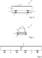
- Fig. 1a shows a carrier unit 12, which is formed by a block 1, namely a solid cuboid.
- the massive cuboid 1 has on its upper surface two longitudinal guides 4 with breadboard.
- the block 1 is held by four feet, which are formed by profile beams 2 and adjustable leveling elements 3. By rotating the leveling elements 3, a height compensation is possible, and the block 1 can be aligned so horizontally.
- Fig. 1b is the carrier unit 12 in a view and in Fig. 1c shown in a side view.
- FIGS. 2a to c Different variants of the longitudinal guide 4 are shown.
- a longitudinal guide 4 is arranged as a raised element in the middle of the block 1.
- the longitudinal guide 4 is designed as a centrally inserted into the surface of the block 1 groove.
- two longitudinal guides 4 in the form of mutually parallel rails on the surface of the block 1 are arranged.
- FIGS. 3a and 3b represent alternative variants for the arrangement of the leveling elements 3 on the underside of the block 1. While according to Fig. 3a three leveling elements are arranged on the underside of the block 1, are according to Fig. 3b four leveling elements 3 arranged on the underside of the block 1.
- the three leveling elements 3 span a triangle or the four leveling elements 3 form a rectangle.
- at least one should be adjustable, while four of the four leveling elements 4 are preferably all adjustable.
- a process carrier system with two carrier units 12 is shown, which are arranged in series.
- the two support units 12 are connected by a coupling element 13 not shown in detail.
- the coupling element 13 can also continue to serve to align the carrier units 12 to a common longitudinal axis. While in Fig. 4 By way of example, only two carrier units 12 are coupled to one another, it is also possible to connect an arbitrarily larger number of carrier units 12 to one another.
- the number of required carrier units 12 is determined by the space required for positioning of process modules on the carrier units 12.
- Fig. 5a shows a processing module 21 in its most general embodiment.
- the processing module 21 has a support structure 25, a transport cylinder 22 and two pulleys 23.
- the processing module 21 is constructed mirror-symmetrically to a symmetry axis S, wherein the axis of symmetry is a vertical axis through the axis of rotation of the transport cylinder 22.
- Fig. 5b the application of the processing module 21 is shown on carrier units 12. Due to its reduced design to the essential elements, the processing module 21 can be used in different positions for different tasks.
- FIGS. 6a to 6c show alternative embodiments of the guide member 24.
- the underside of the support structure 25 of the machining module 21 has been provided with a groove.
- This centrally disposed groove 24 is complementary to the in Fig. 2a shown rail 4 of the carrier unit 12th
- Fig. 6b was mounted on the underside of the processing module 21 as a guide member 24 a rail.
- the rail or the lugs 24 are complementary to the groove 4 of the support unit 12, as in Fig. 2b shown executed.
- the machining module 21 was provided on its underside with two grooves as guide elements 24.
- grooves 24 provide complementary elements to the two rails 4 of the carrier unit 12 - as in FIG Fig. 2c
- the three variants shown are to be regarded as exemplary - all have in common: the longitudinal guides 4 of the carrier unit 12 and the guide elements 24 of the processing modules 21 are formed complementary to each other so that they can interlock and processing modules 21 simply with carrier units 12th can be connected.
- the transport cylinder 22 of the processing module 21 is used in the most general embodiment exclusively for the transport of the web-shaped printing material
- the transport cylinder 22 in the printing modules 7 and 8 forms the counter-pressure cylinder and the punching module 10, the counter-punching cylinder.
- the in the FIGS. 7b or c and d or e illustrated variants, according to which a pressure roller or a UV drying module can be arranged left or right, are used depending on the direction of the web-shaped substrate.
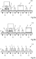
- FIGS. 8a to 8d The combination of the carrier units 12 with processing modules 21 and additional functional units to a narrow-web label printing machine 100 goes out of the FIGS. 8a to 8d out.
- four carrier units 12 were coupled in series and different process modules were positioned on the carrier units 12 according to the requirements of the print job.
- a web transport module 5 For example, a gravure printing module 6, two flexographic printing modules 7, a digital printing module 9, a screen printing module 8 and a stamping module 10 were used.
- Fig. 8b For example, a web transport module 5, a stamping module 10, a gravure printing module 6, a flexographic printing module 7, a screen printing module 8, a further flexographic printing module 7 and a digital printing module were used.
- the first processing module 21 forms a web transport module 5, followed by a screen printing module 8, five flexographic printing modules 7 and an embossing module 11, before another processing module 21, which again forms a web transport module 5, forms the last process module.
- a carrier unit 12 can receive one, two, three or even more processing modules 21 with additional functional units. The latter can - as described above - on the basis of a grid in defined positions or in use a guide without grid freely on the support units 12 are positioned.
- four offset printing modules 14 were also used.
Landscapes
- Engineering & Computer Science (AREA)
- Mechanical Engineering (AREA)
- Printing Methods (AREA)
- Rotary Presses (AREA)
- Coloring (AREA)
- Feeding Of Articles By Means Other Than Belts Or Rollers (AREA)
- Printing Plates And Materials Therefor (AREA)
- Treatment Of Fiber Materials (AREA)
Description
- Die Erfindung betrifft ein Bearbeitungsmodul gemäß dem Oberbegriff von Anspruch 1 und eine Trägereinheit gemäß dem Oberbegriff von Anspruch 6, welche gemeinsam eine Druckmaschine gemäß Anspruch 10 bilden.
- Bei Druckmaschinen zum Bedrucken von Etiketten und Faltschachteln ist in zunehmendem Maße eine große Flexibilität oder Variabilität gewünscht, um möglichst viele verschiedenartige Druckaufträge, insbesondere unter Erzeugung von speziellen optischen Effekten durch das gedruckte Bild oder den gedruckten Text, durchführen zu können. Zur Herstellung von Etiketten und Faltschachteln werden besonders häufig Druckmaschinen verwendet, die eine schmale Bahn eines Bedruckstoffes bearbeiten und eine Anzahl von Verbindungsplattformen oder Schnittstellen aufweisen, an denen jeweils eine Funktionseinheit oder ein Verfahrensmodul zum Drucken mit einem bestimmten Druckverfahren lösbar aufgenommen werden kann. Beispielsweise ist eine Ausführungsform einer derartigen Druckmaschine im Dokument
US 4,384,522 beschrieben. Die einzelnen Funktionseinheiten können dabei mit voneinander verschiedenen Druckverfahren arbeiten. - Aus den Dokumenten
DE 195 13 536 A1 undWO 95/29813 - Schon seit vielen Jahren werden Druckmaschinen und in ihnen zum Einsatz gelangende einzelne Bauteile in großem Umfang aus metallischen Werkstoffen, insbesondere aus Stählen, Aluminium oder Titan, hergestellt. Neben der den Anforderungen entsprechenden Eignung aufgrund einiger ihrer physikalischen und technischen Eigenschaften ist die traditionelle Verwendung dieser Werkstoffe offensichtlich unter anderem darauf zurückzuführen, dass weit verbreitet sowohl qualitative Fertigkeiten als auch quantitative Kapazitäten zur Verfügung stehen, metallische Werkstoffe herzustellen und adäquat zu bearbeiten. In Druckmaschinen mit moderner Drucktechnik gelangen meist große Gussteile aus metallischen Werkstoffen für die Maschinentragkonstruktion zum Einsatz, welche ihre Formgebung in technisch aufwändigen und auch oft kostspieligen Bearbeitungsschritten erfahren. In Konsequenz der Verwendung metallischer Werkstoffe in der modernen Drucktechnik sind in der Regel unterstützende technische Maßnahmen erforderlich, um einigen bestimmten unerwünschten physikalischen Eigenschaften dieser Werkstoffe, wie beispielsweise der elektrischen Leitfähigkeit, der thermischen Ausdehnung oder dem mechanischen Schwingungsverhalten, oder Konsequenzen aus diesen Eigenschaften zu begegnen.
- Beiden vorgenannten Aspekten wird in der
DE 10 2006 042 884 A1 begegnet. Offenbart wird eine Druckmaschine, insbesondere Etikettendruckmaschine oder bogenverarbeitende Offsetdruckmaschine, deren Druckwerke in einer aus Stein gefertigten Maschinentragkonstruktion aufgenommen sind. Dabei können unterschiedliche Druckwerke eingesetzt bzw. ausgetauscht und die Druckmaschine an einen jeweiligen Auftrag angepasst werden. - Um Druckaufträge noch flexibler handhaben und vorhandene Druckmaschinen mit höherer Auslastung betreiben zu können wird in zunehmendem Maß höhere Flexibilität beim Aufbau der Druckmaschine gefordert.
- Eine Druckmaschine in modularem Aufbau wird in der
EP 2 042 315 A2 beschrieben. Eine Mehrzahl von Gestellmodulen kann in Reihe positioniert werden, wozu die Gestellmodule ausgerichtet werden. Die Gestellmodule können mit Verfahrensmodulen bestückt werden, wobei die Verfahrensmodule Bearbeitungszylinder und Bahnleitwalzen aufweisen. - Aufgabe der vorliegenden Erfindung ist es daher eine Druckmaschine zu schaffen, deren Aufbau äußerst flexibel geändert werden kann.
- Gelöst wird diese Aufgabe durch die Schaffung eines Bearbeitungsmoduls gemäß Anspruch 1 und einer Trägereinheit gemäß Anspruch 6, welche gemeinsam eine Druckmaschine gemäß Anspruch 10 bilden. In anderen Worten: Trägereinheiten und Bearbeitungsmodule stehen in einer definierten Beziehung zueinander und sind aneinander besonders angepasst.
- Die erfindungsgemäße Trägereinheit dient der Aufnahme und beliebigen Positionierung von Bearbeitungsmodulen für die Druck- und Druckweiterverarbeitung zum modularen Aufbau einer Schmalbahn-Etikettendruckmaschine. In einer bevorzugten Ausführungsform besitzt die Trägereinheit einen massiven Quader mit mindestens drei Füßen und mindestens einer Längsführung, wobei die Füße an der Unterseite des Quaders angebracht sind und wobei die Längsführung an der Oberseite des Quaders angebracht ist und sich über die Länge des Quaders erstreckt. Eine derartige Trägereinheit ist durch einen sehr einfachen Aufbau gekennzeichnet, was eine einfache und kostengünstige Fertigung der Trägereinheit erlaubt. Besonders vorteilhaft ist es, wenn der Quader aus Naturstein, beispielsweise Granit, oder aus Kunststein, beispielsweise Beton, Mineralgusswerkstoff oder Polymerguss gefertigt ist. Diese Werkstoffe sind wesentlich kostengünstiger als Metallwerkstoffe und haben bessere Eigenschaften bezüglich Schwingungsverhalten, Festigkeit, Verfügbarkeit und Verarbeitbarkeit.
- In einer besonders vorteilhaften und daher bevorzugten Ausführungsform ist die Längsführung als Längsführungsschiene ausgeführt. Diese kann dabei ein Raster, z.B. ein Lochraster, aufweisen. In das Raster können Gegenelemente von Bearbeitungsmodulen eingreifen. Durch das Raster können somit definierte Positionen für die Bearbeitungsmodule vorgegeben werden und diese können in definierten Abständen zueinander auf der Trägereinheit positioniert werden. Ist die Längsführung ohne Raster ausgeführt, so können die Bearbeitungsmodule frei positioniert werden.
- In einer vorteilhaften Weiterbildung der erfindungsgemäßen Trägereinheit verfügt mindestens einer der Füße über ein Nivellierelement zur Höhenveränderung des Quaders. Dadurch können Unebenheiten der Grundfläche ausgeglichen und der Quader in eine waagrechte Lage gebracht werden.
- In einer vorteilhaften Ausführungsvariante besitzt die Trägereinheit Koppelelemente zum Verbinden, d.h. Aneinanderreihen von zwei Trägereinheiten. Diese können über die Koppelelemente relativ zueinander ausgerichtet werden.
- Die Erfindung betrifft auch ein Bearbeitungsmodul für die Druck- und Druckweiterverarbeitung eines bahnförmigen Bedruckstoffes zum Einsatz auf einer wie obenstehend beschriebenen Trägereinheit und zum modularen Aufbau einer Schmalbahn-Druckmaschine. Das Bearbeitungsmodul dient dem Transport und / oder der Bearbeitung des Bedruckstoffes. Erfindungsgemäß besitzt das Bearbeitungsmodul eine Tragstruktur, einen Transportzylinder und zwei Umlenkrollen, wobei die Umlenkrollen spiegelsymmetrisch zu einer vertikalen Symmetrieachse durch die Rotationsachse des Transportzylinders angeordnet sind. Der spiegelsymmetrische Aufbau erlaubt in vorteilhafter Weise, die Laufrichtung des zu bedruckenden und zu bearbeitenden bahnförmigen Bedruckstoffes frei wählen zu können.
- In erfindungsgemäßer Ausführungsform des Bearbeitungsmoduls besitzt die Tragstruktur mindestens ein an ihrer Unterseite angebrachtes Längsführungselement zum Positionieren des Bearbeitungsmoduls auf einer Trägereinheit, insbesondere wie obenstehend beschrieben. In anderen Worten: die Längsführung der Trägereinheit und das Längsführungselement des Bearbeitungsmoduls stellen die Schnittstelle dar, um Trägereinheit und Bearbeitungsmodul miteinander zu verbinden.
- In vorteilhafter Weiterbildung ist die Tragstruktur spiegelsymmetrisch zur vertikalen Achse durch die Rotationsachse des Transportzylinders.
- In Weiterbildung des erfindungsgemäßen Bearbeitungsmoduls kann das Bearbeitungsmodul Schnittstellen aufweisen zur Verbindung mit einer zusätzlichen Funktionseinheit, wobei diese zusätzliche Funktionseinheit zur Ausführung zusätzlicher Bearbeitungsschritte an dem bahnförmigen Bedruckstoff dient. Die zusätzliche Funktionseinheit kann dabei als Druckwerkseinheit ausgeführt sein und zusammen mit den Bearbeitungsmodulen ein Druckwerk bilden. Die zusätzliche Funktionseinheit kann auch als Stanz- und/oder Prägeeinheit ausgeführt sein und zusammen mit dem Bearbeitungsmodul ein Stanz- und/oder -Prägewerk bilden.
- Gegenstand der Erfindung ist auch eine Schmalbahn-Druckmaschine, aufweisend mindestens zwei wie obenstehend beschriebene Trägereinheiten und mindestens drei, wie obenstehend beschriebene Bearbeitungsmodule, wobei die Bearbeitungsmodule auf den Trägereinheiten positioniert sind. Eine derartige Schmalbahn-Druckmaschine kann in vorteilhafter Weise schnell und einfach in ihrem Aufbau geändert und an die Erfordernisse eines jeweiligen Druckauftrags angepasst werden. So ist zum Einen die Anzahl der Bearbeitungsmodule, welche auf den Trägereinheiten positioniert werden können, nicht von Anfang an begrenzt. Zum anderen können die Bearbeitungsmodule in ihrer Position auf den Trägereinheiten variabel verschoben werden. Ein weiterer Vorteil ergibt sich dadurch, dass bei gleichen Trägereinheiten verschiedene Bahnbreiten realisierbar sind: Die Bearbeitungseinheiten stehen bei größeren Bahnbreiten nur weiter über die Trägereinheiten hinaus.
- In vorteilhafter Weiterbildung der erfindungsgemäßen Schmalbahn-Druckmaschine weisen die mindestens eine Längsführung der jeweiligen Trägereinheit und das mindestens eine Längsführungselement des jeweiligen Bearbeitungsmoduls zueinander komplementäre Profilierungen auf. Diese Profilierungen stellen dabei die Schnittstelle von Trägereinheiten und Bearbeitungsmodulen dar, und stellen sicher, dass die Bearbeitungsmodule mit einfachen Handgriffen schnell und unkompliziert auf den Trägereinheiten positioniert und befestigt werden können.
- Die beschriebene Erfindung und die beschriebenen vorteilhaften Weiterbildungen der Erfindung stellen auch in beliebiger Kombination miteinander vorteilhafte Weiterbildungen der Erfindung dar.
- Hinsichtlich weiterer Vorteile und in konstruktiver und funktioneller Hinsicht vorteilhafter Ausgestaltungen der Erfindung wird auf die Unteransprüche sowie die Beschreibung von Ausführungsbeispielen unter Bezugnahme auf die beiliegenden Zeichnungen verwiesen.
- Die Erfindung soll an Hand bevorzugter Ausführungsbeispiele noch näher erläutert werden. Es zeigen in schematischer Darstellung
- Fig. 1a:
- Eine dreidimensionale Darstellung einer erfindungsgemäßen Trägereinheit
- Fig. 1b und 1c:
- Ansichten der Trägereinheit
- Fig. 2a bis 2c:
- Verschiedene Ausführungsformen der Längsführung
- Figuren 3a und 3b:
- Unterschiedliche Ausführungsvarianten zur Anordnung der Füße der Trägereinheit
- Fig. 4:
- Zwei Trägereinheiten, welche in Reihe angeordnet sind
- Fig. 5a:
- Ein Prozessmodul in einer schematischen Darstellung
- Fig. 5b:
- Den Einsatz von Trägereinheiten und Prozessmodulen
- Figuren 6a bis 6c:
- Verschiedene Ausführungsvarianten des Führungselements
- Figuren 7a bis 7k:
- Verschiedene Beispiele zur Anwendung des Bearbeitungsmoduls
- Figuren 8a bis 8d:
- Verschiedene Beispiele für den flexiblen Aufbau der Druckmaschine
- Einander entsprechende Elemente und Bauteile sind in den Figuren mit gleichen Bezugszeichen versehen.
-
Fig. 1a zeigt eine Trägereinheit 12, welche durch einen Block 1, nämlich einen massiven Quader, gebildet wird. Der massive Quader 1 besitzt an seiner oberen Fläche zwei Längsführungen 4 mit Lochraster. Gehalten wird der Block 1 von vier Füßen, welche durch Profilträger 2 und verstellbare Nivellierelemente 3 gebildet werden. Durch Verdrehen der Nivellierelemente 3 ist ein Höhenausgleich möglich, und der Block 1 kann so waagrecht ausgerichtet werden. InFig. 1b ist die Trägereinheit 12 in einer Ansicht und inFig. 1c in einer seitlichen Ansicht dargestellt. - In den
Figuren 2a bis c sind verschiedene Varianten der Längsführung 4 dargestellt. InFig. 2a ist eine Längsführung 4 als erhabenes Element mittig auf dem Block 1 angeordnet. In der Variante gemäßFig. 2b ist die Längsführung 4 als eine mittig in die Oberfläche des Blocks 1 eingebrachte Nut ausgeführt. Gemäß der Darstellung vonFig. 2c sind zwei Längsführungen 4 in Form von zueinander parallelen Schienen auf der Oberfläche des Blocks 1 angeordnet. - Die
Figuren 3a und 3b stellen alternative Varianten für die Anordnung der Nivellierelemente 3 an der Unterseite des Blocks 1 dar. Während gemäßFig. 3a drei Nivellierelemente an der Unterseite des Blocks 1 angeordnet sind, sind gemäßFig. 3b vier Nivellierelemente 3 an der Unterseite des Blocks 1 angeordnet. Die drei Nivellierelemente 3 spannen ein Dreieck bzw. die vier Nivellierelemente 3 ein Rechteck auf. Von den drei Nivellierelementen 3 sollte zumindest eines verstellbar sein, während von den vier Nivellierelementen 4 bevorzugt alle verstellbar ausgeführt sind. - In
Fig. 4 ist ein Prozessträgersystem mit zwei Trägereinheiten 12 dargestellt, welche in Reihe angeordnet sind. Die beiden Trägereinheiten 12 werden durch ein nicht näher dargestelltes Koppelelement 13 miteinander verbunden. Das Koppelelement 13 kann auch weiter dazu dienen, die Trägereinheiten 12 zu einer gemeinsamen Längsachse auszurichten. Während inFig. 4 beispielhaft nur zwei Trägereinheiten 12 miteinander gekoppelt sind, lässt sich auch eine beliebig größere Zahl an Trägereinheiten 12 miteinander verbinden. Die Anzahl erforderlicher Trägereinheiten 12 wird dabei durch den erforderlichen Platzbedarf zur Positionierung von Prozessmodulen auf den Trägereinheiten 12 bestimmt. -
Fig. 5a zeigt ein Bearbeitungsmodul 21 in seiner allgemeinsten Ausführungsform. Das Bearbeitungsmodul 21 besitzt eine Tragstruktur 25, einen Transportzylinder 22 und zwei Umlenkrollen 23. Das Bearbeitungsmodul 21 ist spiegelsymmetrisch zu einer Symmetrieachse S aufgebaut, wobei die Symmetrieachse eine vertikale Achse durch die Drehachse des Transportzylinders 22 ist. - In
Fig. 5b ist die Anwendung des Bearbeitungsmoduls 21 auf Trägereinheiten 12 dargestellt. Aufgrund seines auf die wesentlichen Elemente reduzierten Aufbaus kann das Bearbeitungsmodul 21 an verschiedenen Positionen für unterschiedliche Aufgaben eingesetzt werden. -
Figuren 6a bis 6c zeigen alternative Ausführungsformen des Führungselements 24. Gemäß der Darstellung vonFig. 6a wurde die Unterseite der Tragstruktur 25 des Bearbeitungsmoduls 21 mit einer Nut versehen. Diese mittig angeordnete Nut 24 ist dabei komplementär zur inFig. 2a gezeigten Schiene 4 der Trägereinheit 12.
In der Variante vonFig. 6b wurde an der Unterseite des Bearbeitungsmoduls 21 als Führungselement 24 eine Schiene angebracht. Alternativ zu einer durchgehenden Schiene könnten auch mindestens zwei separate Nasen verwendet werden. Die Schiene bzw. die Nasen 24 sind dabei komplementär zur Nut 4 der Trägereinheit 12, wie inFig. 2b dargestellt, ausgeführt.
In der Variante vonFig. 6c wurde das Bearbeitungsmodul 21 an seiner Unterseite mit zwei Nuten als Führungselemente 24 versehen. Diese Nuten 24 stellen komplementäre Elemente zu den zwei Schienen 4 der Trägereinheit 12 - wie inFig. 2c dargestellt - dar. Die drei dargestellten Varianten sind als beispielhaft zu betrachten - allen gemeinsam ist jedoch: die Längsführungen 4 der Trägereinheit 12 und die Führungselemente 24 der Bearbeitungsmodule 21 sind komplementär zueinander ausgeformt, so dass diese ineinander greifen können und Bearbeitungsmodule 21 einfach mit Trägereinheiten 12 verbunden werden können. - In den
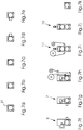
Figuren 7a bis 7k sind verschiedene Anwendungen des Bearbeitungsmoduls 21 dargestellt. Es zeigen: - Fig. 7a:
- das Bearbeitungsmodul 21 als Basismodul mit oder ohne Zylinderkühlung, mit oder ohne Messwalzen, mit oder ohne Anpresswalze und
- Fig. 7b:
- das Bearbeitungsmodul 21 als Basismodul mit oder ohne Zylinderkühlung, mit oder ohne Messwalzen, jedoch mit Anpresswalze links und
- Fig. 7c:
- das Bearbeitungsmodul 21 als Basismodul mit oder ohne Zylinderkühlung, mit oder ohne Messwalzen, jedoch mit Anpresswalze auf der rechten Seite und
- Fig. 7d:
- das Bearbeitungsmodul 21 mit Zylinderkühlung, ohne Messwalzen, aber mit UV-Trocknung rechts und
- Fig. 7e:
- das Bearbeitungsmodul 21 mit Zylinderkühlung, ohne Messwalzen, jedoch mit UV-Trocknung auf der linken Seite und
- Fig. 7f:
- das Bearbeitungsmodul 21 zusammen mit einer zusätzlichen Funktionseinheit, nämlich eine Rotationssiebdruckeinheit mit UV-Trocknung rechts und gekühltem Zylinder, so dass ein Siebdruckmodul 8 gebildet wird und
- Fig. 7g:
- das Bearbeitungsmodul 21 zusammen mit einer Flexodruckwerkseinheit für Rückseitendruck mit UV auf der linken Seite und gekühltem Zylinder, so dass ein Flexodruckmodul 7 gebildet wird und
- Fig. 7h:
- das Bearbeitungsmodul 21 zusammen mit einer zusätzlichen Funktionseinheit, nämlich einer Kaltfolien- oder Laminiereinheit und einem gekühlten Zylinder und
- Fig. 7i:
- ein Bearbeitungsmodul 21 mit einem zusätzlichen Rotations-Heißfolienprägewerk ohne Kühlung, so dass ein Prägemodul 11 gebildet wird und
- Fig. 7j:
- ein Bearbeitungsmodul 21 mit einer zusätzlichen Funktionseinheit, nämlich einem Rotationsstanzwerk, sodass ein Stanzmodul 10 gebildet wird und
- Fig. 7k:
- ein Bearbeitungsmodul 21 als Bahnzugstation mit Messwalze für die Bahnspannungskontrolle.
- Während der Transportzylinder 22 des Bearbeitungsmoduls 21 in dessen allgemeinster Ausführungsform ausschließlich dem Transport des bahnförmigen Bedruckstoffes dient, bildet der Transportzylinder 22 in den Druckmodulen 7 und 8 den Gegendruckzylinder und im Stanzmodul 10 den Gegenstanzzylinder. Die in den
Figuren 7b bzw. c und d bzw. e dargestellten Varianten, gemäß denen eine Anpresswalze bzw. ein UV-Trocknungsmodul links oder rechts angeordnet sein kann, sind je nach Laufrichtung des bahnförmigen Bedruckstoffs einzusetzen. - Die Kombination der Trägereinheiten 12 mit Bearbeitungsmodulen 21 und zusätzlichen Funktionseinheiten zu einer Schmalbahn-Etikettendruckmaschine 100 geht aus den
Figuren 8a bis 8d hervor. In allen drei Beispielen wurden vier Trägereinheiten 12 in Reihe gekoppelt und auf den Trägereinheiten 12 entsprechend den Anforderungen des Druckauftrags unterschiedliche Prozessmodule positioniert. Im Beispiel vonFig. 8a wurde ein Bahntransportmodul 5, ein Tiefdruckmodul 6, zwei Flexodruckmodule 7, ein Digitaldruckmodul 9, ein Siebdruckmodul 8 und ein Stanzmodul 10 verwendet. Gemäß dem Beispiel vonFig. 8b wurde ein Bahntransportmodul 5, ein Stanzmodul 10, ein Tiefdruckmodul 6, ein Flexodruckmodul 7, ein Siebdruckmodul 8, ein weiteres Flexodruckmodul 7 und ein Digitaldruckmodul verwendet. Im Beispiel vonFig. 8c bildet das erste Bearbeitungsmodul 21 ein Bahntransportmodul 5, worauf ein Siebdruckmodul 8, fünf Flexodruckmodule 7 und ein Prägemodul 11 folgen, bevor ein weiteres Bearbeitungsmodul 21, welches erneut ein Bahntransportmodul 5 bildet, das letzte Prozessmodul bildet. Eine Trägereinheit 12 kann dabei ein, zwei, drei oder auch mehr Bearbeitungsmodule 21 mit zusätzlichen Funktionseinheiten aufnehmen. Letztere können - wie oben beschrieben - an Hand eines Rasters in definierte Positionen oder bei Einsatz einer Führung ohne Raster frei auf den Trägereinheiten 12 positioniert werden. Im Beispiel vonFig. 8d wurden neben einem Flexodruckmodul 7 und einem Siebdruckmodul 8 auch vier Offsetdruckmodule 14 verwendet. -
- 1
- Block
- 2
- Profil
- 3
- Nivellierelement
- 4
- Längsführung mit Lochraster
- 5
- Prozessmodul 1 (z. B. Bahntransportmodul)
- 6
- Prozessmodul 2 (z. B. Tiefdruckmodul)
- 7
- Prozessmodul 3 (z. B. Flexodruckmodul)
- 8
- Prozessmodul 4 (z. B. Siebdruckmodul)
- 9
- Prozessmodul 5 (z. B. Digitaldruckmodul)
- 10
- Prozessmodul 6 (z. B. Stanzmodul)
- 11
- Prozessmodul 7 (z. B. Prägemodul)
- 12
- Prozessträger-System (Trägereinheit)
- 13
- Koppelelement
- 14
- Prozessmodul 8 (z.B. Offsetdruckmodul)
- 21
- Bearbeitungsmodul
- 22
- Transportzylinder
- 23
- Umlenkrolle
- 24
- Führungselement
- 25
- Tragstruktur
- 100
- Schmalbahn-Etikettendruckmaschine
- S
- Symmetrieachse
Claims (11)
- Bearbeitungsmodul (21) für die Druck- und Druckweiterverarbeitung eines bahnförmigen Bedruckstoffes zum Einsatz auf einer Trägereinheit (12), und zum modularen Aufbau einer Schmalbahn-Etikettendruckmaschine (100),
wobei das Bearbeitungsmodul (21) eine Tragstruktur (25), einen Transportzylinder (22) und zwei Umlenkrollen (23) besitzt, wobei die Umlenkrollen (23) spiegelsymmetrisch zu einer vertikalen Symmetrieachse (S) durch die Rotationsachse des Transportzylinders (22) angeordnet sind,
dadurch gekennzeichnet,
dass die Tragstruktur (25) mindestens ein an ihrer Unterseite angebrachtes Längsführungselement (24) besitzt zum Positionieren des Bearbeitungsmoduls (21) auf der mindestens eine Längsführung (4) aufweisenden Trägereinheit (12). - Bearbeitungsmodul nach Anspruch 1,
dadurch gekennzeichnet,
dass die Tragstruktur (25) spiegelsymmetrisch zur Symmetrieachse (S) ist. - Bearbeitungsmodul nach einem der vorangehenden Ansprüche,
dadurch gekennzeichnet,
dass das Bearbeitungsmodul (21) mindestens eine Schnittstelle aufweist zur Verbindung mit einer zusätzlichen Funktionseinheit zur Ausführung zusätzlicher Bearbeitungsschritte an dem bahnförmigen Bedruckstoff. - Bearbeitungsmodul nach Anspruch 3,
dadurch gekennzeichnet,
dass die zusätzliche Funktionseinheit als Druckwerkseinheit ausgeführt ist und zusammen mit dem Bearbeitungsmodul (21) ein Druckwerk (6, 7, 8, 9) bildet. - Bearbeitungsmodul nach Anspruch 3,
dadurch gekennzeichnet,
dass die zusätzliche Funktionseinheit als Stanz- und/oder Prägeeinheit ausgeführt ist und zusammen mit dem Bearbeitungsmodul (21) ein Stanz- und/oder Prägewerk (10, 11) bildet. - Trägereinheit (12) zur Aufnahme und beliebigen Positionierung von Bearbeitungsmodulen (21) für die Druck- und Druckweiterverarbeitung nach einem der Ansprüche 1 - 5 zum modularen Aufbau einer Schmalbahn-Etikettendruckmaschine (100),
dadurch gekennzeichnet,
dass die Trägereinheit (12) einen massiven Quader (1) mit mindestens drei Füßen (3) und mindestens einer Längsführung (4) besitzt, wobei die Füße (3) an der Unterseite des Quaders (1) angebracht sind und wobei die Längsführung (4) an der Oberseite des Quaders (1) angebracht ist und sich über die Länge des Quaders (1) erstreckt. - Trägereinheit nach Anspruch 6,
dadurch gekennzeichnet,
dass der Quader (1) aus Naturstein, insbesondere Granit, oder aus Kunststein, insbesondere Beton, gefertigt ist. - Trägereinheit nach einem der Ansprüche 6 oder 7,
dadurch gekennzeichnet,
dass die Längsführung (4) als Längsführungsschiene ausgeführt ist und insbesondere ein Raster aufweist. - Trägereinheit nach einem der Ansprüche 6 bis 8,
dadurch gekennzeichnet,
dass mindestens einer der Füße (3) über ein Nivellierelement zur Höhenveränderung des Quaders (1) verfügt. - Schmalbahn-Druckmaschine (100) aufweisend mindestens zwei Trägereinheiten (12) nach einem der Ansprüche 6 bis 9 und mindestens drei Bearbeitungsmodule (21) nach einem der Ansprüche 1 bis 5, wobei die Bearbeitungsmodule (21) auf den Trägereinheiten (12) positioniert sind.
- Schmalbahn-Druckmaschine nach Anspruch 10,
dadurch gekennzeichnet,
dass die mindestens eine Längsführung (4) der jeweiligen Trägereinheit (12) und das mindestens eine Längsführungselement (24) des jeweiligen Bearbeitungsmoduls (21) zueinander komplementäre Profilierungen aufweisen.
Applications Claiming Priority (1)
| Application Number | Priority Date | Filing Date | Title |
|---|---|---|---|
| DE102012003157A DE102012003157A1 (de) | 2012-02-16 | 2012-02-16 | Trägereinheit und Bearbeitungsmodul zum Aufbau einer Druckmaschine |
Publications (2)
| Publication Number | Publication Date |
|---|---|
| EP2628593A1 EP2628593A1 (de) | 2013-08-21 |
| EP2628593B1 true EP2628593B1 (de) | 2017-04-19 |
Family
ID=47678622
Family Applications (1)
| Application Number | Title | Priority Date | Filing Date |
|---|---|---|---|
| EP13153784.7A Not-in-force EP2628593B1 (de) | 2012-02-16 | 2013-02-04 | Trägereinheit und Bearbeitungsmodul zum Aufbau einer Druckmaschine |
Country Status (5)
| Country | Link |
|---|---|
| EP (1) | EP2628593B1 (de) |
| CN (1) | CN103252979B (de) |
| DE (1) | DE102012003157A1 (de) |
| DK (1) | DK2628593T3 (de) |
| IN (1) | IN2013CH00559A (de) |
Families Citing this family (5)
| Publication number | Priority date | Publication date | Assignee | Title |
|---|---|---|---|---|
| DE102016213438A1 (de) | 2016-07-22 | 2018-01-25 | Gallus Druckmaschinen Gmbh | Bahndruckmaschine mit Bearbeitungsmodulen und Trägermodulen |
| EP3388239A1 (de) * | 2017-04-15 | 2018-10-17 | FVK Reklam Matbaa Yayin Sanayi ve Ticaret Limited Sirketi | Druck-, schneide- und bohrmaschine, die kontinuierliche herstellung über eine einzige linie ermöglicht |
| CN107187178A (zh) * | 2017-05-31 | 2017-09-22 | 江阴市汇通包装机械有限公司 | 药用铝箔涂布印刷机 |
| EP4098445B1 (de) * | 2021-05-31 | 2025-08-13 | Bobst Bielefeld GmbH | Druckanordnung |
| DE102021132121A1 (de) * | 2021-12-07 | 2023-06-07 | Koenig & Bauer Ag | Maschine sowie Verfahren zum Be- und/oder Verarbeiten von bahnförmigem Substrat |
Family Cites Families (11)
| Publication number | Priority date | Publication date | Assignee | Title |
|---|---|---|---|---|
| US4384522A (en) | 1977-12-07 | 1983-05-24 | Paper Converting Machine Company | Apparatus for producing business forms |
| DE9318226U1 (de) * | 1993-11-29 | 1994-01-27 | Man Roland Druckmaschinen Ag, 63069 Offenbach | Unterbau für eine Rollen-Rotationsdruckmaschine |
| DE69503370T2 (de) | 1994-04-28 | 1998-10-29 | Nilpeter As | Druckvorrichtung mit wenigstens einer modularer druckeinheit |
| DE19513536A1 (de) | 1995-04-10 | 1996-10-17 | Heidelberger Druckmasch Ag | Druckmaschine mit mehreren Druckwerken |
| DE20006513U1 (de) * | 2000-04-08 | 2000-07-13 | MAN Roland Druckmaschinen AG, 63075 Offenbach | Bogen-Rotationsdruckmaschine |
| DE102004053739A1 (de) * | 2004-11-06 | 2006-05-11 | Man Roland Druckmaschinen Ag | Druckeinheit einer Druckmaschine |
| GB2428634B (en) * | 2005-08-04 | 2008-09-17 | Goss Graphic Systems Ltd | Printing press |
| DE102006042884A1 (de) * | 2006-09-13 | 2008-03-27 | Gallus Druckmaschinen Gmbh | Druckmaschine |
| DE102007045876A1 (de) * | 2007-09-25 | 2009-04-09 | Gallus Druckmaschinen Gmbh | Druckwerk und Druckmaschine |
| DE102008013315A1 (de) * | 2008-03-10 | 2009-09-17 | Gallus Druckmaschinen Gmbh | Druckwerk und Druckmaschine |
| DE102008025650A1 (de) * | 2008-05-28 | 2009-12-10 | Gallus Stanz- Und Druckmaschinen Gmbh | Druckwerk zum Bedrucken einer Bedruckstoffbahn in einer Druckmaschine |
-
2012
- 2012-02-16 DE DE102012003157A patent/DE102012003157A1/de not_active Withdrawn
-
2013
- 2013-02-04 EP EP13153784.7A patent/EP2628593B1/de not_active Not-in-force
- 2013-02-04 DK DK13153784.7T patent/DK2628593T3/en active
- 2013-02-11 IN IN559CH2013 patent/IN2013CH00559A/en unknown
- 2013-02-16 CN CN201310051039.1A patent/CN103252979B/zh not_active Expired - Fee Related
Also Published As
| Publication number | Publication date |
|---|---|
| DK2628593T3 (en) | 2017-07-10 |
| EP2628593A1 (de) | 2013-08-21 |
| IN2013CH00559A (de) | 2015-08-14 |
| DE102012003157A1 (de) | 2013-08-22 |
| CN103252979B (zh) | 2017-06-30 |
| CN103252979A (zh) | 2013-08-21 |
| DE102012003157A8 (de) | 2013-11-07 |
Similar Documents
| Publication | Publication Date | Title |
|---|---|---|
| DE4327278C2 (de) | Traggestell für eine Rollenrotationsdruckmaschine | |
| DE10008215A1 (de) | Druckwerk für eine Rotationsmaschine mit Kreuzschlitten | |
| EP2628593A1 (de) | Trägereinheit und Bearbeitungsmodul zum Aufbau einer Druckmaschine | |
| EP2551078B1 (de) | Vorrichtung zum Stanzen mit einstellbarem Zylinderabstand | |
| DE69803352T2 (de) | Vorrichtung zum Ausrichten und Festlegen von Werkzeugen auf eine Heiz- und Trägerplatte | |
| DE102009002871A1 (de) | Hebeeinrichtung einer Druckmaschine und ein Verfahren zur Veränderung einer Höhe einer Hebeeinrichtung und ein Verfahren zur Veränderung einer Breite einer Hebeeinrichtung | |
| DE19833467C2 (de) | Offsetrotationsdruckmaschine | |
| DE102005046303A1 (de) | Druckeinheit | |
| DE3235775A1 (de) | Unterwerkzeug fuer eine abkantpresse | |
| DE102010037865B4 (de) | Drucktucheinheit | |
| EP3272535B1 (de) | Bahndruckmaschine mit bearbeitungsmodulen und trägermodulen | |
| DE102011108954A1 (de) | Vorrichtung zum Stanzen mit hydrostatischer Zylinderlagerung | |
| DE10321989B4 (de) | Druckmaschine | |
| DE102008035677B4 (de) | Druckeinheit für eine Rollenrotationsdruckmaschine | |
| DE102004011070B4 (de) | Ausbaubare Druckeinheit für Rollen-Offsetdruckmaschinen | |
| DE102007000865B4 (de) | Druckeinheit mit mindestens zwei relativ zueinander in einer horizontalen Richtung abstandsveränderbaren Seitengestellteilen | |
| DE102007025499A1 (de) | Rotationsdruckmaschine | |
| DE102016108673A1 (de) | Presse zum Herstellen von Feinschneidteilen | |
| CH699806A2 (de) | Verfahren zur Herstellung von Rakeln. | |
| DE102017215062B3 (de) | Vorrichtung zur Vermeidung von Resonanzschwingungen in Drucktürmen sowie Druckmaschine mit einer solchen Vorrichtung | |
| EP1769913A2 (de) | Rotationsdruckmaschine mit ersten und zweiten Seitenwandelementen | |
| DE102005048918B4 (de) | Rollenrotationsdruckmaschine | |
| DE202005020987U1 (de) | Druckeinheit | |
| DE19919530A1 (de) | Gestelle zur Bahnführung in Druckmaschinen | |
| DE202005021002U1 (de) | Druckeinheit |
Legal Events
| Date | Code | Title | Description |
|---|---|---|---|
| PUAI | Public reference made under article 153(3) epc to a published international application that has entered the european phase |
Free format text: ORIGINAL CODE: 0009012 |
|
| AK | Designated contracting states |
Kind code of ref document: A1 Designated state(s): AL AT BE BG CH CY CZ DE DK EE ES FI FR GB GR HR HU IE IS IT LI LT LU LV MC MK MT NL NO PL PT RO RS SE SI SK SM TR |
|
| AX | Request for extension of the european patent |
Extension state: BA ME |
|
| 17P | Request for examination filed |
Effective date: 20140221 |
|
| RBV | Designated contracting states (corrected) |
Designated state(s): AL AT BE BG CH CY CZ DE DK EE ES FI FR GB GR HR HU IE IS IT LI LT LU LV MC MK MT NL NO PL PT RO RS SE SI SK SM TR |
|
| 17Q | First examination report despatched |
Effective date: 20160421 |
|
| GRAP | Despatch of communication of intention to grant a patent |
Free format text: ORIGINAL CODE: EPIDOSNIGR1 |
|
| STAA | Information on the status of an ep patent application or granted ep patent |
Free format text: STATUS: GRANT OF PATENT IS INTENDED |
|
| GRAJ | Information related to disapproval of communication of intention to grant by the applicant or resumption of examination proceedings by the epo deleted |
Free format text: ORIGINAL CODE: EPIDOSDIGR1 |
|
| STAA | Information on the status of an ep patent application or granted ep patent |
Free format text: STATUS: EXAMINATION IS IN PROGRESS |
|
| INTG | Intention to grant announced |
Effective date: 20161118 |
|
| GRAP | Despatch of communication of intention to grant a patent |
Free format text: ORIGINAL CODE: EPIDOSNIGR1 |
|
| STAA | Information on the status of an ep patent application or granted ep patent |
Free format text: STATUS: GRANT OF PATENT IS INTENDED |
|
| INTC | Intention to grant announced (deleted) | ||
| INTG | Intention to grant announced |
Effective date: 20161219 |
|
| GRAS | Grant fee paid |
Free format text: ORIGINAL CODE: EPIDOSNIGR3 |
|
| GRAA | (expected) grant |
Free format text: ORIGINAL CODE: 0009210 |
|
| STAA | Information on the status of an ep patent application or granted ep patent |
Free format text: STATUS: THE PATENT HAS BEEN GRANTED |
|
| AK | Designated contracting states |
Kind code of ref document: B1 Designated state(s): AL AT BE BG CH CY CZ DE DK EE ES FI FR GB GR HR HU IE IS IT LI LT LU LV MC MK MT NL NO PL PT RO RS SE SI SK SM TR |
|
| REG | Reference to a national code |
Ref country code: GB Ref legal event code: FG4D Free format text: NOT ENGLISH |
|
| REG | Reference to a national code |
Ref country code: CH Ref legal event code: EP |
|
| REG | Reference to a national code |
Ref country code: AT Ref legal event code: REF Ref document number: 885554 Country of ref document: AT Kind code of ref document: T Effective date: 20170515 |
|
| REG | Reference to a national code |
Ref country code: IE Ref legal event code: FG4D Free format text: LANGUAGE OF EP DOCUMENT: GERMAN |
|
| REG | Reference to a national code |
Ref country code: DE Ref legal event code: R096 Ref document number: 502013006988 Country of ref document: DE |
|
| REG | Reference to a national code |
Ref country code: NL Ref legal event code: FP |
|
| REG | Reference to a national code |
Ref country code: DK Ref legal event code: T3 Effective date: 20170703 |
|
| REG | Reference to a national code |
Ref country code: LT Ref legal event code: MG4D |
|
| PG25 | Lapsed in a contracting state [announced via postgrant information from national office to epo] |
Ref country code: LT Free format text: LAPSE BECAUSE OF FAILURE TO SUBMIT A TRANSLATION OF THE DESCRIPTION OR TO PAY THE FEE WITHIN THE PRESCRIBED TIME-LIMIT Effective date: 20170419 Ref country code: FI Free format text: LAPSE BECAUSE OF FAILURE TO SUBMIT A TRANSLATION OF THE DESCRIPTION OR TO PAY THE FEE WITHIN THE PRESCRIBED TIME-LIMIT Effective date: 20170419 Ref country code: HR Free format text: LAPSE BECAUSE OF FAILURE TO SUBMIT A TRANSLATION OF THE DESCRIPTION OR TO PAY THE FEE WITHIN THE PRESCRIBED TIME-LIMIT Effective date: 20170419 Ref country code: ES Free format text: LAPSE BECAUSE OF FAILURE TO SUBMIT A TRANSLATION OF THE DESCRIPTION OR TO PAY THE FEE WITHIN THE PRESCRIBED TIME-LIMIT Effective date: 20170419 Ref country code: NO Free format text: LAPSE BECAUSE OF FAILURE TO SUBMIT A TRANSLATION OF THE DESCRIPTION OR TO PAY THE FEE WITHIN THE PRESCRIBED TIME-LIMIT Effective date: 20170719 Ref country code: GR Free format text: LAPSE BECAUSE OF FAILURE TO SUBMIT A TRANSLATION OF THE DESCRIPTION OR TO PAY THE FEE WITHIN THE PRESCRIBED TIME-LIMIT Effective date: 20170720 |
|
| PG25 | Lapsed in a contracting state [announced via postgrant information from national office to epo] |
Ref country code: IS Free format text: LAPSE BECAUSE OF FAILURE TO SUBMIT A TRANSLATION OF THE DESCRIPTION OR TO PAY THE FEE WITHIN THE PRESCRIBED TIME-LIMIT Effective date: 20170819 Ref country code: BG Free format text: LAPSE BECAUSE OF FAILURE TO SUBMIT A TRANSLATION OF THE DESCRIPTION OR TO PAY THE FEE WITHIN THE PRESCRIBED TIME-LIMIT Effective date: 20170719 Ref country code: LV Free format text: LAPSE BECAUSE OF FAILURE TO SUBMIT A TRANSLATION OF THE DESCRIPTION OR TO PAY THE FEE WITHIN THE PRESCRIBED TIME-LIMIT Effective date: 20170419 Ref country code: SE Free format text: LAPSE BECAUSE OF FAILURE TO SUBMIT A TRANSLATION OF THE DESCRIPTION OR TO PAY THE FEE WITHIN THE PRESCRIBED TIME-LIMIT Effective date: 20170419 Ref country code: PL Free format text: LAPSE BECAUSE OF FAILURE TO SUBMIT A TRANSLATION OF THE DESCRIPTION OR TO PAY THE FEE WITHIN THE PRESCRIBED TIME-LIMIT Effective date: 20170419 Ref country code: RS Free format text: LAPSE BECAUSE OF FAILURE TO SUBMIT A TRANSLATION OF THE DESCRIPTION OR TO PAY THE FEE WITHIN THE PRESCRIBED TIME-LIMIT Effective date: 20170419 |
|
| REG | Reference to a national code |
Ref country code: DE Ref legal event code: R097 Ref document number: 502013006988 Country of ref document: DE |
|
| PG25 | Lapsed in a contracting state [announced via postgrant information from national office to epo] |
Ref country code: SK Free format text: LAPSE BECAUSE OF FAILURE TO SUBMIT A TRANSLATION OF THE DESCRIPTION OR TO PAY THE FEE WITHIN THE PRESCRIBED TIME-LIMIT Effective date: 20170419 Ref country code: CZ Free format text: LAPSE BECAUSE OF FAILURE TO SUBMIT A TRANSLATION OF THE DESCRIPTION OR TO PAY THE FEE WITHIN THE PRESCRIBED TIME-LIMIT Effective date: 20170419 Ref country code: RO Free format text: LAPSE BECAUSE OF FAILURE TO SUBMIT A TRANSLATION OF THE DESCRIPTION OR TO PAY THE FEE WITHIN THE PRESCRIBED TIME-LIMIT Effective date: 20170419 Ref country code: EE Free format text: LAPSE BECAUSE OF FAILURE TO SUBMIT A TRANSLATION OF THE DESCRIPTION OR TO PAY THE FEE WITHIN THE PRESCRIBED TIME-LIMIT Effective date: 20170419 |
|
| PLBE | No opposition filed within time limit |
Free format text: ORIGINAL CODE: 0009261 |
|
| STAA | Information on the status of an ep patent application or granted ep patent |
Free format text: STATUS: NO OPPOSITION FILED WITHIN TIME LIMIT |
|
| PG25 | Lapsed in a contracting state [announced via postgrant information from national office to epo] |
Ref country code: SM Free format text: LAPSE BECAUSE OF FAILURE TO SUBMIT A TRANSLATION OF THE DESCRIPTION OR TO PAY THE FEE WITHIN THE PRESCRIBED TIME-LIMIT Effective date: 20170419 |
|
| 26N | No opposition filed |
Effective date: 20180122 |
|
| PG25 | Lapsed in a contracting state [announced via postgrant information from national office to epo] |
Ref country code: SI Free format text: LAPSE BECAUSE OF FAILURE TO SUBMIT A TRANSLATION OF THE DESCRIPTION OR TO PAY THE FEE WITHIN THE PRESCRIBED TIME-LIMIT Effective date: 20170419 |
|
| REG | Reference to a national code |
Ref country code: CH Ref legal event code: PL |
|
| PG25 | Lapsed in a contracting state [announced via postgrant information from national office to epo] |
Ref country code: MT Free format text: LAPSE BECAUSE OF FAILURE TO SUBMIT A TRANSLATION OF THE DESCRIPTION OR TO PAY THE FEE WITHIN THE PRESCRIBED TIME-LIMIT Effective date: 20170419 Ref country code: MC Free format text: LAPSE BECAUSE OF FAILURE TO SUBMIT A TRANSLATION OF THE DESCRIPTION OR TO PAY THE FEE WITHIN THE PRESCRIBED TIME-LIMIT Effective date: 20170419 |
|
| GBPC | Gb: european patent ceased through non-payment of renewal fee |
Effective date: 20180204 |
|
| REG | Reference to a national code |
Ref country code: IE Ref legal event code: MM4A |
|
| REG | Reference to a national code |
Ref country code: BE Ref legal event code: MM Effective date: 20180228 |
|
| PG25 | Lapsed in a contracting state [announced via postgrant information from national office to epo] |
Ref country code: LU Free format text: LAPSE BECAUSE OF NON-PAYMENT OF DUE FEES Effective date: 20180204 Ref country code: LI Free format text: LAPSE BECAUSE OF NON-PAYMENT OF DUE FEES Effective date: 20180228 Ref country code: CH Free format text: LAPSE BECAUSE OF NON-PAYMENT OF DUE FEES Effective date: 20180228 |
|
| REG | Reference to a national code |
Ref country code: FR Ref legal event code: ST Effective date: 20181031 |
|
| PG25 | Lapsed in a contracting state [announced via postgrant information from national office to epo] |
Ref country code: IE Free format text: LAPSE BECAUSE OF NON-PAYMENT OF DUE FEES Effective date: 20180204 |
|
| PG25 | Lapsed in a contracting state [announced via postgrant information from national office to epo] |
Ref country code: GB Free format text: LAPSE BECAUSE OF NON-PAYMENT OF DUE FEES Effective date: 20180204 Ref country code: BE Free format text: LAPSE BECAUSE OF NON-PAYMENT OF DUE FEES Effective date: 20180228 Ref country code: FR Free format text: LAPSE BECAUSE OF NON-PAYMENT OF DUE FEES Effective date: 20180228 |
|
| REG | Reference to a national code |
Ref country code: AT Ref legal event code: MM01 Ref document number: 885554 Country of ref document: AT Kind code of ref document: T Effective date: 20180204 |
|
| PG25 | Lapsed in a contracting state [announced via postgrant information from national office to epo] |
Ref country code: AT Free format text: LAPSE BECAUSE OF NON-PAYMENT OF DUE FEES Effective date: 20180204 |
|
| PG25 | Lapsed in a contracting state [announced via postgrant information from national office to epo] |
Ref country code: TR Free format text: LAPSE BECAUSE OF FAILURE TO SUBMIT A TRANSLATION OF THE DESCRIPTION OR TO PAY THE FEE WITHIN THE PRESCRIBED TIME-LIMIT Effective date: 20170419 |
|
| PGFP | Annual fee paid to national office [announced via postgrant information from national office to epo] |
Ref country code: DE Payment date: 20200229 Year of fee payment: 8 |
|
| PG25 | Lapsed in a contracting state [announced via postgrant information from national office to epo] |
Ref country code: HU Free format text: LAPSE BECAUSE OF FAILURE TO SUBMIT A TRANSLATION OF THE DESCRIPTION OR TO PAY THE FEE WITHIN THE PRESCRIBED TIME-LIMIT; INVALID AB INITIO Effective date: 20130204 Ref country code: PT Free format text: LAPSE BECAUSE OF FAILURE TO SUBMIT A TRANSLATION OF THE DESCRIPTION OR TO PAY THE FEE WITHIN THE PRESCRIBED TIME-LIMIT Effective date: 20170419 |
|
| PG25 | Lapsed in a contracting state [announced via postgrant information from national office to epo] |
Ref country code: MK Free format text: LAPSE BECAUSE OF NON-PAYMENT OF DUE FEES Effective date: 20170419 Ref country code: CY Free format text: LAPSE BECAUSE OF FAILURE TO SUBMIT A TRANSLATION OF THE DESCRIPTION OR TO PAY THE FEE WITHIN THE PRESCRIBED TIME-LIMIT Effective date: 20170419 |
|
| PG25 | Lapsed in a contracting state [announced via postgrant information from national office to epo] |
Ref country code: AL Free format text: LAPSE BECAUSE OF FAILURE TO SUBMIT A TRANSLATION OF THE DESCRIPTION OR TO PAY THE FEE WITHIN THE PRESCRIBED TIME-LIMIT Effective date: 20170419 |
|
| PGFP | Annual fee paid to national office [announced via postgrant information from national office to epo] |
Ref country code: IT Payment date: 20210226 Year of fee payment: 9 Ref country code: NL Payment date: 20210219 Year of fee payment: 9 |
|
| PGFP | Annual fee paid to national office [announced via postgrant information from national office to epo] |
Ref country code: DK Payment date: 20210219 Year of fee payment: 9 |
|
| REG | Reference to a national code |
Ref country code: DE Ref legal event code: R119 Ref document number: 502013006988 Country of ref document: DE |
|
| PG25 | Lapsed in a contracting state [announced via postgrant information from national office to epo] |
Ref country code: DE Free format text: LAPSE BECAUSE OF NON-PAYMENT OF DUE FEES Effective date: 20210901 |
|
| REG | Reference to a national code |
Ref country code: DK Ref legal event code: EBP Effective date: 20220228 |
|
| REG | Reference to a national code |
Ref country code: NL Ref legal event code: MM Effective date: 20220301 |
|
| PG25 | Lapsed in a contracting state [announced via postgrant information from national office to epo] |
Ref country code: NL Free format text: LAPSE BECAUSE OF NON-PAYMENT OF DUE FEES Effective date: 20220301 |
|
| PG25 | Lapsed in a contracting state [announced via postgrant information from national office to epo] |
Ref country code: DK Free format text: LAPSE BECAUSE OF NON-PAYMENT OF DUE FEES Effective date: 20220228 |
|
| PG25 | Lapsed in a contracting state [announced via postgrant information from national office to epo] |
Ref country code: IT Free format text: LAPSE BECAUSE OF NON-PAYMENT OF DUE FEES Effective date: 20220204 |