EP2628635B1 - Anordnung zum Festhalten eines Zweiradfahrzeugs auf einem Transportfahrzeug - Google Patents
Anordnung zum Festhalten eines Zweiradfahrzeugs auf einem Transportfahrzeug Download PDFInfo
- Publication number
- EP2628635B1 EP2628635B1 EP13151198.2A EP13151198A EP2628635B1 EP 2628635 B1 EP2628635 B1 EP 2628635B1 EP 13151198 A EP13151198 A EP 13151198A EP 2628635 B1 EP2628635 B1 EP 2628635B1
- Authority
- EP
- European Patent Office
- Prior art keywords
- hollow axle
- transport
- vehicle
- wheeled vehicle
- clamping
- Prior art date
- Legal status (The legal status is an assumption and is not a legal conclusion. Google has not performed a legal analysis and makes no representation as to the accuracy of the status listed.)
- Active
Links
Images

Classifications
-
- B—PERFORMING OPERATIONS; TRANSPORTING
- B60—VEHICLES IN GENERAL
- B60P—VEHICLES ADAPTED FOR LOAD TRANSPORTATION OR TO TRANSPORT, TO CARRY, OR TO COMPRISE SPECIAL LOADS OR OBJECTS
- B60P3/00—Vehicles adapted to transport, to carry or to comprise special loads or objects
- B60P3/06—Vehicles adapted to transport, to carry or to comprise special loads or objects for carrying vehicles
- B60P3/07—Vehicles adapted to transport, to carry or to comprise special loads or objects for carrying vehicles for carrying road vehicles
- B60P3/073—Vehicle retainers
- B60P3/075—Vehicle retainers for wheels, hubs, or axle shafts
Definitions
- the invention relates to an arrangement for holding a two-wheeled vehicle on a transport vehicle, wherein at least one wheel of the two-wheeled vehicle has a hollow axle with a coaxial through-opening and the wheel has a compressible tire with a transport plane of the transport vehicle to which the two-wheeled vehicle with its wheels is adjustable , with one or more tensionable tension members, which engage the two-wheeled vehicle and the transport vehicle and by which the two-wheeled vehicle can be tensioned against the transport plane of the transport vehicle.
- the object of the invention is therefore to provide a simply constructed arrangement of the type mentioned, which allows avoiding damage to parts of the two-wheeled vehicle safe transport of the Zwelrad familias.
- a fastener the hollow axis of the wheel can be arranged outstanding, at the both sides of the through hole projecting ends each having a pulling element with its one end can be fastened, which is fastened with its other end to the transport vehicle, wherein the wheel under a certain compression of its tire is braced against the transport plane.
- Two-wheeled vehicles can be eg bicycles or motorcycles.
- the fastening element can be permanently fixedly arranged in the hollow axle.
- the fastening element can be connected by a releasable connection fixedly connected to the hollow axle and connected only to a transport operation with the hollow shaft.
- the fastener may be formed in several parts and having two support members, wherein the support members have a greater radial extent than the through hole of the hollow shaft and each supported at one axial end of the hollow shaft and both support members by means of a clamping device connected to each other and axially against the ends the hollow axle are tensioned.
- the support members of the hollow shaft facing axial guide ends have smaller radial extent than the through hole of the hollow shaft, wherein the leading ends project into the through hole.
- the support parts are necessarily guided coaxially to the hollow axle.
- an adaptation to different diameters of the through holes of different hollow axes is also inevitably.
- the same fastener may be used in different two-wheeled vehicles with different hollow axes.
- Rejuvenating conically can be a stage rejuvenation of the leaders.
- the clamping device may be a clamping screw through which the two support members are connected to each other and axially clamped against the ends of the hollow shaft.
- the clamping screw can project through a coaxial bore of a support member and be axially supported with its screw head on the end remote from the hollow axis of this one support member and facing away from the screw head, provided with a threaded other end portion in a Koaxialgewindebohrung of the other support member or an axial clamping sleeve, wherein the Axialspannhülse projects through a coaxial bore of the other support member and at its end remote from the hollow axle has a sleeve head and is supported on the hollow axis facing away from the end face of the other support member.
- the one ends of the traction elements can be firmly connected to their respective associated Abstütz Workshopen.
- the one ends of the tension members are detachably connectable to their respective associated Abstschreib Anlagenen.
- the support parts may have attachment recesses or attachment hooks, into which hooks or eyes of the traction elements can be hooked.
- the mounting recesses may be on the lateral surface of the support members radially encircling retaining grooves.
- the other ends of the traction elements can be firmly connected to the transport vehicle.
- the other ends of the tension members are releasably connectable to the transport vehicle.
- the tension members have fastening recesses or fastening hooks, in which hooks or eyes of the transport vehicle can be hooked.
- the tension members may be straps.
- the tension members can be set by tensioning devices under tension.
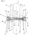
- the illustrated arrangement for holding a two-wheeled vehicle on a transport plane 20 of a transport vehicle shows a wheel 1 of a motorcycle.
- the wheel 1 has a hollow shaft 2, on which a telescopic fork 3 of the frame, not shown, of the motorcycle is supported.
- a support member 4 is arranged, which has a coaxial conically tapered leading end 5, which projects partially into the through hole 6 of the hollow shaft 2.
- the large diameter of the cone 7 is greater than the diameter of the through hole 6 and the smallest diameter of the cone 7 is smaller than the diameter of the through hole 6 of the hollow shaft. 2
- the support members 4 are based with their cones 7 axially from the mouth ends of the polar axis 2.
- Both support members 4 have a continuous stepped coaxial bore 8, the large step 9 facing away from the hollow shaft 2 and the small step 10 of the hollow shaft 2 faces.
- a clamping screw 11 is inserted, which is axially supported with its screw head 12 at the shoulder of the transition from the large to the small stage 9, 10.
- the protruding into the through hole 6 shank of the clamping screw 11 is provided at its end remote from the screw head 12 with a thread 13.
- an axial clamping sleeve 14 is inserted, which is axially supported with its screw head 15 at the shoulder of the transition from the large to the small stage 9, 10.
- the protruding into the through hole 6 shank of Axialspannhülse 14 has a Koaxialgewindebohrung 16, in which the clamping screw 11 is screwed with its thread 13 and the two support members 4 firmly clamped against the end faces of the hollow shaft 2.
- the support members 4 and the clamping screw 11 and the axial clamping sleeve 14 form a fixedly arranged on the hollow shaft 2 fastener.
- the support parts 4 are approximately cylindrical and provided with a radially circumferential retaining groove 17 on the lateral surface of the cylindrical region.
- the straps 18 are connected at one end to the support members 4 and at its other ends to the transport plane 20 and tensioned by tensioning devices 21, the tension straps 18.
- the wheel 1 is firmly clamped under a certain compression of its tire against the transport plane 20, while the frame and the suspension of the motorcycle remain unclamped.
Landscapes
- Engineering & Computer Science (AREA)
- Health & Medical Sciences (AREA)
- Public Health (AREA)
- Transportation (AREA)
- Mechanical Engineering (AREA)
- Axle Suspensions And Sidecars For Cycles (AREA)
- Motorcycle And Bicycle Frame (AREA)
- Handcart (AREA)
Description
- Die Erfindung bezieht sich auf eine Anordnung zum Festhalten eines Zweiradfahrzeugs auf einem Transportfahrzeug, wobei mindestens ein Rad des Zweiradfahrzeugs eine Hohlachse mit einer koaxialen Durchgangsöffnung und das Rad einen kompressierbaren Reifen aufweist, mit einer Transportebene des Transportfahrzeugs, auf die das Zweiradfahrzeug mit seinen Rädern stellbar ist, mit einem oder mehreren spannbaren Zugorganen, die an dem Zweiradfahrzeug sowie an dem Transportfahrzeug angreifen und durch die das Zweiradfahrzeug gegen die Transport-ebene des Transportfahrzeugs spannbar ist.
- Bei einer derartigen Anordnung (
US 2006/0186162 A1 ) ist es bekannt, daß die Zugorgane an einem Teil des des Zweiradfahrzeugs angreifen und das Zweiradfahrzeug auf die Transportebene des Transportfahrzeugs spannen. Durch das Spannen eines Teils des Zweiradfahrzeugs auf die Transportebene werden auch die Federungen des Zweiradfahrzeugs um zumindest einen großen Teil ihres Federwegs komprimiert, damit das Zweiradfahrzeug bei Schwingungen während des Transportbetriebs nicht von der Transportebene abheben kann. Ein häufigeres Komprimierthalten der Federungen des Zweiradfahrzeugs führt zu einer Funktionsreduktion und letztendllch zu einem Ausfall der Federungen. - Aus der
US 2009/0250564 A1 ist eine Anordnung zum Festhalten eines Zweiradfahrzeugs auf einer Transportebene eines Transportfahrzeugs bekannt, bei der eine Haltevorrichtung auf der Transportebene fest angeordnet ist, die zwei senkrechte, entsprechend einem Lochraster teleskopisch verlängerbare Ständer besitzt. Das eine Hohlachse aufweisende Rad des Zweiradfahrzeugs wird zwischen den beiden Ständern angeordnet und eine Stange durch die Hohlachse geschoben, deren beidseitig aus der Hohlachse herausschauende Enden mittels Riegeleinrichfungen mit den oberen Enden der Ständer verbindbar sind. Dazu sind vorher die Ständer auf eine solche Höhe einzustellen, daß deren Riegeleinrichtungen auf gleicher Höhe mit der Stange sind. - Eine nach dem gleichen Prinzip aufgebaute Anordnung ist aus der
US 2006/0171790 A1 und derUS 2008/0174088 A1 bekannt. - Aus der
WO98/19884 A1 - Aus der
US 7 287 942 B1 Ist eine Anordnung zum Festhalten eines Zweiradfahrzeugs auf einer Transportebene eines Transportfahrzeugs bekannt, bei der die Anordnung zwei Haltearme aufweist, die mit ihren einen Enden an einer Stange angreifen, die durch die Hohlachse des Hinterrades des Zweiradfahrzeugs hindurchragt. Die Haltearme ragen hinter das Hinterrad zu einer an der Transportebene befestigten Halteplatte. - Aufgabe der Erfindung ist es daher eine einfach aufgebaute Anordnung der eingangs genannten Art zu schaffen, die eine Beschädigung von Teilen des Zweiradfahrzeugs vermeidend einen sicheren Transport des Zwelradfahrzeugs ermöglicht.
- Diese Aufgabe wird erfindungsgemäß dadurch gelöst, daß ein Befestigungselement die Hohlachse des Rades durchragend anordenbar ist, an deren beidseitig aus der Durchgangsöffnung herausragenden Enden jeweils ein Zugorgan mit seinem einen Ende befestigbar ist, das mit seinem anderen Ende an dem Transportfahrzeug befestigbar ist, wobei das Rad unter einer bestimmten Kompression seines Reifens gegen die Transportebene verspannt ist.
- Durch diese Ausbildung wird nicht der Rahmen sondern nur ein Rad gegen die Transportebene des Transportfahrzeugs verspannt, so daß kleine Komprimierung der Federungen des Zweiradfahrzeugs erfolgt. Damit können diese Federungen auch nicht aufgrund permanenter Kompression während des Transportbetriebes defekt gehen. Die Verspannung des Rades gegen die Transportebene erfolgt durch eine bestimmte Kompression seines Reifens.
- Zweiradfahrzeuge können z.B. Fahrräder oder auch Motorräder sein.
- Das Befestigungselement kann permanent fest in der Hohlachse angeordnet sein.
- Um im normalen Fahrbetrieb des Zweiradfahrzeugs die ungefederten Massen reduziert zu halten, kann das Befestigungselement durch eine lösbare Verbindung fest mit der Hohlachse verbindbar sein und nur zu einem Transportbetrieb mit der Hohlachse verbunden werden.
- Zur einfachen Montierbarkeit kann dabei das Befestigungselement mehrteilig ausgebildet sein und zwei Abstützteile aufweisen, wobei die Abstützteile eine größere radiale Erstreckung als die Durchgangsbohrung der Hohlachse besitzen und je an einem axialen Ende der Hohlachse abstützbar sowie beide Abstützteile mittels einer Spannvorrichtung miteinander verbindbar und axial gegen die Enden der Hohlachse spannbar sind.
- Zur montageerleichternden Führung der Abstützteile axial zur Hohlachse können die Abstützteile der Hohlachse zugewandte axiale Führungsenden geringerer radialer Erstreckung als die Durchgangsbohrung der Hohlachse aufweisen, wobei die Führungsenden in die Durchgangsbohrung hineinragen.
- Sind dabei die Führungsenden in die Hohlachse hinein sich konisch oder konischartig verjüngend ausgebildet, wobei der größte Durchmesser des Konus größer und der kleinste Durchmesser des Konus kleiner als der Durchmesser der Durchgangsbohrung der Hohlachse ist, so werden die Abstützteile zwangsläufig koaxial zur Hohlachse geführt. Gleichzeitig erfolgt ebenfalls zwangsläufig eine Anpassung an unterschiedliche Durchmesser der Durchgangsbohrungen von unterschiedlichen Hohlachsen. Damit kann dasselbe Befestigungselement bei unterschiedlichen Zweiradfahrzeugen mit unterschiedlichen Hohlachsen zur Anwendung kommen.
- Konischartig verjüngend kann eine stufige Verjüngung der Führungsenden sein.
- In einfacher und kostengünstiger Ausbildung kann die Spannvorrichtung eine Spannschraube sein, durch die die beiden Abstützteile miteinander verbindbar und axial gegen die Enden der Hohlachse spannbar sind.
- Dabei kann die Spannschraube eine Koaxialbohrung des einen Abstützteils durchragen und mit ihrem Schraubenkopf an der der Hohlachse abgewandten Stirnseite dieses einen Abstützteils axial abgestützt sein sowie mit ihren dem Schraubenkopf abgewandten, mit einem Gewinde versehenen anderen Endbereich in eine Koaxialgewindebohrung des anderen Abstützteils oder einer Axialspannhülse einschraubbar sein, wobei die Axialspannhülse eine Koaxialbohrung des anderen Abstützteils durchragt und an ihrem der Hohlachse abgewandten Ende einen Hülsenkopf aufweist sowie an der der Hohlachse abgewandten Stirnseite des anderen Abstützteils abgestützt ist.
- Die einen Enden der Zugorgane können fest mit den ihnen jeweils zugeordneten Abstützstücken verbunden sein.
- Es ist aber auch möglich, daß die einen Enden der Zugorgane lösbar mit den ihnen jeweils zugeordneten Abstützstücken verbindbar sind.
- Dazu können in einfacher Ausbildung die Abstützteile Befestigungsausnehmungen oder Befestigungshaken aufweisen, in die Haken oder Ösen der Zugorgane einhakbar sind.
- Die Befestigungsausnehmungen können dabei an der Mantelfläche der Abstützteile radial umlaufende Haltenuten sein.
- Zur Befestigung der Zugorgane an dem Transportfahrzeug können die anderen Enden der Zugorgane fest mit dem Transportfahrzeug verbunden sein.
- Es ist aber auch möglich, daß die anderen Enden der Zugorgane lösbar mit dem Transportfahrzeug verbindbar sind.
- Dazu können in einfacher Weise die Zugorgane Befestigungsausnehmungen oder Befestigungshaken aufweisen, in die Haken oder Ösen des Transportfahrzeugs einhakbar sind.
- Als Zugorgane sind alle eine Zugspannung erzeugenden Zugelemente anwendbar. Kostengünstig weil handelsüblich können die Zugorgane Spanngurte sein.
- Zur Erzeugung der Zugspannung bei der Befestigung des Zweiradfahrzeugs auf dem Transportfahrzeug können die Zugorgane durch Spannvorrichtungen unter Zugspannung setzbar sein.
- Ein Ausführungsbeispiel der Erfindung ist in der Zeichnung dargestellt und wird im folgenden näher beschrieben. Es zeigen
- Figur 1
- eine Frontansicht einer Anordnung zum Festhalten eines Zweiradfahrzeugs auf einer Transportebene eines Transportfahrzeugs
- Figur 2
- einen vergrößerten Ausschnitt der Anordnung nach
Figur 1 . - Die dargestellte Anordnung zum Festhalten eines Zweiradfahrzeugs auf einer Transportebene 20 eines Transportfahrzeugs zeigt ein Rad 1 eines Motorrads.
- Das Rad 1 besitzt eine Hohlachse 2, an der über eine Teleskopgabel 3 der nicht dargestellte Rahmen des Motorrads abgestützt ist.
- An jedem der beiden axialen Enden der Hohlachse 2 ist ein Abstützteil 4 angeordnet, das ein koaxiales konisch sich verjüngendes Führungsende 5 aufweist, das teilweise in die Durchgangsbohrung 6 der Hohlachse 2 hineinragt.
- Dabei ist der große Durchmesser des Konus 7 größer als der Durchmesser der Durchgangsbohrung 6 und der kleinste Durchmesser des Konus 7 kleiner als der Durchmesser der Durchgangsbohrung 6 der Hohlachse 2.
- Dadurch stützen sich die Abstützteile 4 mit ihren Konusen 7 axial an den Mündungsenden der Polachse 2 ab.
- Beide Abstützteile 4 weisen eine durchgehende stufige Koaxialbohrung 8 auf, deren große Stufe 9 der Hohlachse 2 abgewandt und deren kleine Stufe 10 der Hohlachse 2 zugewandt ist.
- In die Koaxialbohrung 8 des linken Abstützteils 4 ist eine Spannschraube 11 eingeführt, die mit ihrem Schraubenkopf 12 an der Schulter des Übergangs von der großen zur kleinen Stufe 9, 10 axial abgestützt ist.
- Der in die Durchgangsbohrung 6 hineinragende Schaft der Spannschraube 11 ist an seinem dem Schraubenkopf 12 abgewandten Endbereich mit einem Gewinde 13 versehen.
- In die Koaxialbohrung 8 des rechten Abstützteils 4 ist eine Axialspannhülse 14 eingeführt, die mit ihrem Schraubenkopf 15 an der Schulter des Übergangs von der großen zur kleinen Stufe 9, 10 axial abgestützt ist.
- Der in die Durchgangsbohrung 6 hineinragende Schaft der Axialspannhülse 14 weist eine Koaxialgewindebohrung 16 auf, in die die Spannschraube 11 mit ihrem Gewinde 13 eingeschraubt ist und die beiden Abstützteile 4 fest gegen die Stirnseiten der Hohlachse 2 verspannt.
- Damit bilden die Abstützteile 4 und die Spannschraube 11 sowie die Axialspannhülse 14 ein fest an der Hohlachse 2 angeordnetes Befestigungselement.
- An ihren der Hohlachse 2 abgewandten Endbereichen sind die Abstützteile 4 annähernd zylindrisch ausgebildet und an der Mantelfläche des zylindrischen Bereichs mit einer radial umlaufenden Haltenut 17 versehen.
- An den Haltenuten 17 greifen die einen Enden von Spanngurten 18 an, deren andere Enden mit Halteelementen 19 an den seitlichen Randbereichen der Transportebene 20 des ansonsten nicht dargestellten Transportfahrzeugs angreifen.
- Nach dem in Fahrtrichtung ausgerichteten mittigen Aufstellen des Motorrads auf die Transportebene 20 werden die Spanngurte 18 mit ihren einen Enden mit den Abstützteilen 4 und mit ihren anderen Enden mit der Transportebene 20 verbunden und durch Spannvorrichtungen 21 die Spanngurte 18 gespannt.
- Dabei wird das Rad 1 unter einer bestimmten Kompression seines Reifens fest gegen die Transportebene 20 verspannt, während der Rahmen und die Federung des Motorrads unverspannt bleiben.
-
- 1
- Rad
- 2
- Hohlachse
- 3
- Teleskopgabel
- 4
- Abstützteil
- 5
- Führungsende
- 6
- Durchgangsbohrung
- 7
- Konus
- 8
- Koaxialbohrung
- 9
- große Stufe
- 10
- kleine Stufe
- 11
- Spannschraube
- 12
- Schraubenkopf
- 13
- Gewinde
- 14
- Axialspannhülse
- 15
- Schraubenkopf
- 16
- Koaxialgewindebohrung
- 17
- Haltenut
- 18
- Spanngurt
- 19
- Halteelement
- 20
- Transportebene
- 21
- Spannvorrichtung
Claims (10)
- Anordnung zum Festhalten eines Zweiradfahrzeugs mit Rahmen und Federung auf einem Transportfahrzeug, wobei mindestens ein Rad (1) des Zweiradfahrzeugs eine Hohlachse (2) mit einer koaxialen Durchgangsöffnung (6) und das Rad (1) einen kompressierbaren Reifen aufweist, mit einer Transportebene (20) des Transportfahrzeugs, auf die das Zweiradfahrzeug mit seinen Rädern stellbar ist, mit einem oder mehreren Zugorganen, die an dem Zweiradfahrzeug sowie an dem Transportfahrzeug angreifen und durch die das Zweiradfahrzeug gegen die Transportebene (20) des Transportfahrzeugs spannbar ist, wobei ein Befestigungselement die Hohlachse (2) des Rades (1) durchragend angeordnet ist, dadurch gekennzeichnet, daß an den beidseitig aus der Durchgangsöffnung (6) herausragenden Enden des Befestigunsgelementes jeweils ein spannbares Zugorgan mit seinem einen Ende befestigt ist, das mit seinem anderen Ende an dem Transportfahrzeug befestigbar ist, wobei das Rad (1) unter einer bestimmten Kompression seines Reifens gegen die Transportebene (20) verspannt ist, während der Rahmen und die Federung unverspannt bleiben.
- Vorrichtung nach Anspruch 1, dadurch gekennzeichnet, daß das Befestigungselement durch eine lösbare Verbindung fest mit der Hohlachse (2) verbindbar ist.
- Vorrichtung nach Anspruch 2, dadurch gekennzeichnet, daß das Befestigungselement mehrteilig ausgebildet ist und zwei Abstützteile (4) aufweist, wobei die Abstützteile (4) eine größere radiale Erstreckung als die Durchgangsbohrung (6) der Hohlachse (2) besitzen und je an einem axialen Ende der Hohlachse (2) abstützbar sowie beide Abstützteile (4) mittels einer Spannvorrichtung miteinander verbindbar und axial gegen die Enden der Hohlachse (2) spannbar sind.
- Vorrichtung nach Anspruch 3, dadurch gekennzeichnet, daß die Abstützteile (4) der Hohlachse (2) zugewandte axiale Führungsenden (5) geringerer radialer Erstreckung als die Durchgangsbohrung (6) der Hohlachse (2) aufweisen, wobei die Führungsenden (5) in die Durchgangsbohrung (6) hineinragen.
- Vorrichtung nach einem der Ansprüche 3 bis 4, dadurch gekennzeichnet, daß die Spannvorrichtung eine Spannschraube (11) ist.
- Vorrichtung nach Anspruch 5, dadurch gekennzeichnet, daß die Spannschraube (11) eine Koaxialbohrung (8) des einen Abstützteils (4) durchragt und mit ihrem Schraubenkopf (12) an der der Hohlachse (2) abgewandten Stirnseite dieses einen Abstützteils (4) axial abgestützt ist sowie mit ihren dem Schraubenkopf (12) abgewandten, mit einem Gewinde (13) versehenen anderen Endbereich in eine Koaxialgewindebohrung (16) des anderen Abstützteils (4) oder einer Axialspannhülse (14) einschraubbar ist, wobei die Axialspannhülse (14) eine Koaxialbohrung (8) des anderen Abstützteils (4) durchragt und an ihrem der Hohlachse (2) abgewandten Ende einen Hülsenkopf (15) aufweist sowie an der der Hohlachse (2) abgewandten Stirnseite des anderen Abstützteils (4) abgestützt ist.
- Vorrichtung nach einem der Ansprüche 1 bis 6, dadurch gekennzeichnet, daß die einen Enden der Zugorgane lösbar mit den ihnen jeweils zugeordneten Abstützstücken (4) verbindbar sind.
- Vorrichtung nach einem der Ansprüche 1 bis 7, dadurch gekennzeichnet, daß die anderen Enden der Zugorgane lösbar mit dem Transportfahrzeug verbindbar sind.
- Vorrichtung nach einem der vorhergehenden Ansprüche, dadurch gekennzeichnet, daß die Zugorgane Spanngurte (18) sind.
- Anordnung nach einem der vorhergehenden Ansprüche, dadurch gekennzeichnet, daß die Zugorgane durch Spannvorrichtungen (21) unter Zugspannung setzbar sind.
Applications Claiming Priority (1)
| Application Number | Priority Date | Filing Date | Title |
|---|---|---|---|
| DE201210101192 DE102012101192A1 (de) | 2012-02-15 | 2012-02-15 | Anordnung zum Festhalten eines Zweiradfahrzeugs auf einem Transportfahrzeug |
Publications (2)
| Publication Number | Publication Date |
|---|---|
| EP2628635A1 EP2628635A1 (de) | 2013-08-21 |
| EP2628635B1 true EP2628635B1 (de) | 2016-03-30 |
Family
ID=47603300
Family Applications (1)
| Application Number | Title | Priority Date | Filing Date |
|---|---|---|---|
| EP13151198.2A Active EP2628635B1 (de) | 2012-02-15 | 2013-01-14 | Anordnung zum Festhalten eines Zweiradfahrzeugs auf einem Transportfahrzeug |
Country Status (2)
| Country | Link |
|---|---|
| EP (1) | EP2628635B1 (de) |
| DE (1) | DE102012101192A1 (de) |
Families Citing this family (2)
| Publication number | Priority date | Publication date | Assignee | Title |
|---|---|---|---|---|
| US9663016B1 (en) | 2016-03-30 | 2017-05-30 | Scott Sutton | Systems and methods for a motorcycle mount |
| DE202018100033U1 (de) * | 2018-01-03 | 2018-01-17 | Ronny Kölbl | Vorrichtung zur Halterung eines Zweirads an einem Strukturteil |
Family Cites Families (9)
| Publication number | Priority date | Publication date | Assignee | Title |
|---|---|---|---|---|
| US5823723A (en) * | 1996-11-05 | 1998-10-20 | Teftec Corporation | Vehicle wheel tiedown |
| DE20303717U1 (de) * | 2003-03-08 | 2003-06-05 | Westdeutscher Drahtseil-Verkauf Dolezych GmbH & Co., 44147 Dortmund | Zurrgurt zur Festlegung von Fahrzeugen, insbesondere Zweirädern, auf einer Transportfläche |
| GB2430922B (en) * | 2004-07-03 | 2008-03-26 | Kenneth Johnson | Security device |
| US7198443B2 (en) * | 2005-02-03 | 2007-04-03 | Macomber Iii Chester E | Motorcycle transport system and method therefor |
| US20060186162A1 (en) * | 2005-02-23 | 2006-08-24 | Stubbs Kent A | Motorcycle tie-down system |
| US7578646B2 (en) * | 2005-06-03 | 2009-08-25 | Shaw Michael B | Anchoring system for motorized and non-motorized craft |
| US7648317B2 (en) * | 2007-01-19 | 2010-01-19 | Abranda, Llc. | Motorcycle transport stand |
| US20080226410A1 (en) * | 2007-03-12 | 2008-09-18 | Pit Bull Products, Inc. | Motorcycle restraint system |
| US8485369B2 (en) * | 2007-12-18 | 2013-07-16 | Woodrow Loyd Glover | Motorcycle stand |
-
2012
- 2012-02-15 DE DE201210101192 patent/DE102012101192A1/de not_active Ceased
-
2013
- 2013-01-14 EP EP13151198.2A patent/EP2628635B1/de active Active
Also Published As
| Publication number | Publication date |
|---|---|
| EP2628635A1 (de) | 2013-08-21 |
| DE102012101192A1 (de) | 2013-08-22 |
Similar Documents
| Publication | Publication Date | Title |
|---|---|---|
| EP3195982B1 (de) | Spannvorrichtung für eine schraubverbindung, verfahren zum anziehen einer schraubverbindung sowie gewindemutter | |
| DE102010024572A1 (de) | Aufpralldämpfungsstruktur mit Crashboxen | |
| DE202015005524U1 (de) | Schnellverschluss für Fahrräder mit Justierfunktion | |
| DE2807343A1 (de) | Selbstzentrierende vorrichtung zur befestigung eines fahrzeugrades auf der achse einer auswuchtmaschine | |
| EP2628635B1 (de) | Anordnung zum Festhalten eines Zweiradfahrzeugs auf einem Transportfahrzeug | |
| EP3514434A1 (de) | Rohrschelle | |
| DE2932580A1 (de) | Vorrichtung zur befestigung einer spreizbaren nabe in einer bohrung | |
| DE69614840T2 (de) | Lösbare nabe für die montage eines drehenden teils auf einer antriebswelle und mit einer lösbaren nabe dieser art versehendes drehendes teil | |
| DE1279496B (de) | Zusatzgewicht zur Befestigung an der Radscheibe von Fahrzeugraedern, insbesondere Treibraedern landwirtschaftlich genutzter Motorfahrzeuge | |
| WO2014067900A1 (de) | Schraubverbindungsanordnung | |
| DE202018100033U1 (de) | Vorrichtung zur Halterung eines Zweirads an einem Strukturteil | |
| DE1004436B (de) | Vorrichtung zur Befestigung der Kolbenstange am Kreuzkopf bei Kolbenmaschinen | |
| DE19506332A1 (de) | Hilfsvorrichtung für Fahrradwerkstätten | |
| DE2461465C3 (de) | Einrichtung zum Aufspannen von Autorädern unterschiedlicher Felgenausführung auf einem Wellenende einer Auswuchtmaschine | |
| DE20014480U1 (de) | Hilfseinrichtung zum Montieren eines Fahrzeugrades | |
| DE202018102191U1 (de) | Adapter zum Ankoppeln eines Fahrradanhängers an einem Fahrrad sowie Fahrrad mit einem solchen Adapter | |
| DE10327557B4 (de) | Befestigungseinrichtung für ein Reserverad | |
| DE212016000078U1 (de) | Radständer | |
| DE102022100697A1 (de) | Höhenverstellbarer Lenkervorbau | |
| DE202006014102U1 (de) | Vorrichtung zum Abziehen einer Lagernabe | |
| DE9115070U1 (de) | Speichenrad für Fahrzeuge, insbesondere für Fahrräder | |
| DE102016116261B4 (de) | Kupplung für einen Fahrradanhänger | |
| DE677091C (de) | Rohrverbindung fuer Fahrraeder u. dgl. | |
| DE112006000040B4 (de) | Vorrichtung zur Sicherung eines Rades in einer Gabel | |
| DE202007018023U1 (de) | Vorrichtung zum Halten eines Kettenschutzes für ein Zweirad |
Legal Events
| Date | Code | Title | Description |
|---|---|---|---|
| PUAI | Public reference made under article 153(3) epc to a published international application that has entered the european phase |
Free format text: ORIGINAL CODE: 0009012 |
|
| AK | Designated contracting states |
Kind code of ref document: A1 Designated state(s): AL AT BE BG CH CY CZ DE DK EE ES FI FR GB GR HR HU IE IS IT LI LT LU LV MC MK MT NL NO PL PT RO RS SE SI SK SM TR |
|
| AX | Request for extension of the european patent |
Extension state: BA ME |
|
| 17P | Request for examination filed |
Effective date: 20131231 |
|
| RBV | Designated contracting states (corrected) |
Designated state(s): AL AT BE BG CH CY CZ DE DK EE ES FI FR GB GR HR HU IE IS IT LI LT LU LV MC MK MT NL NO PL PT RO RS SE SI SK SM TR |
|
| GRAP | Despatch of communication of intention to grant a patent |
Free format text: ORIGINAL CODE: EPIDOSNIGR1 |
|
| INTG | Intention to grant announced |
Effective date: 20150922 |
|
| GRAS | Grant fee paid |
Free format text: ORIGINAL CODE: EPIDOSNIGR3 |
|
| GRAA | (expected) grant |
Free format text: ORIGINAL CODE: 0009210 |
|
| AK | Designated contracting states |
Kind code of ref document: B1 Designated state(s): AL AT BE BG CH CY CZ DE DK EE ES FI FR GB GR HR HU IE IS IT LI LT LU LV MC MK MT NL NO PL PT RO RS SE SI SK SM TR |
|
| REG | Reference to a national code |
Ref country code: GB Ref legal event code: FG4D Free format text: NOT ENGLISH |
|
| REG | Reference to a national code |
Ref country code: CH Ref legal event code: EP |
|
| REG | Reference to a national code |
Ref country code: AT Ref legal event code: REF Ref document number: 784989 Country of ref document: AT Kind code of ref document: T Effective date: 20160415 |
|
| REG | Reference to a national code |
Ref country code: IE Ref legal event code: FG4D Free format text: LANGUAGE OF EP DOCUMENT: GERMAN |
|
| REG | Reference to a national code |
Ref country code: DE Ref legal event code: R096 Ref document number: 502013002326 Country of ref document: DE |
|
| REG | Reference to a national code |
Ref country code: LT Ref legal event code: MG4D |
|
| PG25 | Lapsed in a contracting state [announced via postgrant information from national office to epo] |
Ref country code: NO Free format text: LAPSE BECAUSE OF FAILURE TO SUBMIT A TRANSLATION OF THE DESCRIPTION OR TO PAY THE FEE WITHIN THE PRESCRIBED TIME-LIMIT Effective date: 20160630 Ref country code: HR Free format text: LAPSE BECAUSE OF FAILURE TO SUBMIT A TRANSLATION OF THE DESCRIPTION OR TO PAY THE FEE WITHIN THE PRESCRIBED TIME-LIMIT Effective date: 20160330 Ref country code: FI Free format text: LAPSE BECAUSE OF FAILURE TO SUBMIT A TRANSLATION OF THE DESCRIPTION OR TO PAY THE FEE WITHIN THE PRESCRIBED TIME-LIMIT Effective date: 20160330 Ref country code: GR Free format text: LAPSE BECAUSE OF FAILURE TO SUBMIT A TRANSLATION OF THE DESCRIPTION OR TO PAY THE FEE WITHIN THE PRESCRIBED TIME-LIMIT Effective date: 20160701 |
|
| REG | Reference to a national code |
Ref country code: NL Ref legal event code: MP Effective date: 20160330 |
|
| PG25 | Lapsed in a contracting state [announced via postgrant information from national office to epo] |
Ref country code: LT Free format text: LAPSE BECAUSE OF FAILURE TO SUBMIT A TRANSLATION OF THE DESCRIPTION OR TO PAY THE FEE WITHIN THE PRESCRIBED TIME-LIMIT Effective date: 20160330 Ref country code: RS Free format text: LAPSE BECAUSE OF FAILURE TO SUBMIT A TRANSLATION OF THE DESCRIPTION OR TO PAY THE FEE WITHIN THE PRESCRIBED TIME-LIMIT Effective date: 20160330 Ref country code: LV Free format text: LAPSE BECAUSE OF FAILURE TO SUBMIT A TRANSLATION OF THE DESCRIPTION OR TO PAY THE FEE WITHIN THE PRESCRIBED TIME-LIMIT Effective date: 20160330 Ref country code: SE Free format text: LAPSE BECAUSE OF FAILURE TO SUBMIT A TRANSLATION OF THE DESCRIPTION OR TO PAY THE FEE WITHIN THE PRESCRIBED TIME-LIMIT Effective date: 20160330 |
|
| PG25 | Lapsed in a contracting state [announced via postgrant information from national office to epo] |
Ref country code: NL Free format text: LAPSE BECAUSE OF FAILURE TO SUBMIT A TRANSLATION OF THE DESCRIPTION OR TO PAY THE FEE WITHIN THE PRESCRIBED TIME-LIMIT Effective date: 20160330 |
|
| PG25 | Lapsed in a contracting state [announced via postgrant information from national office to epo] |
Ref country code: EE Free format text: LAPSE BECAUSE OF FAILURE TO SUBMIT A TRANSLATION OF THE DESCRIPTION OR TO PAY THE FEE WITHIN THE PRESCRIBED TIME-LIMIT Effective date: 20160330 Ref country code: PL Free format text: LAPSE BECAUSE OF FAILURE TO SUBMIT A TRANSLATION OF THE DESCRIPTION OR TO PAY THE FEE WITHIN THE PRESCRIBED TIME-LIMIT Effective date: 20160330 Ref country code: IS Free format text: LAPSE BECAUSE OF FAILURE TO SUBMIT A TRANSLATION OF THE DESCRIPTION OR TO PAY THE FEE WITHIN THE PRESCRIBED TIME-LIMIT Effective date: 20160730 |
|
| PG25 | Lapsed in a contracting state [announced via postgrant information from national office to epo] |
Ref country code: ES Free format text: LAPSE BECAUSE OF FAILURE TO SUBMIT A TRANSLATION OF THE DESCRIPTION OR TO PAY THE FEE WITHIN THE PRESCRIBED TIME-LIMIT Effective date: 20160330 Ref country code: SM Free format text: LAPSE BECAUSE OF FAILURE TO SUBMIT A TRANSLATION OF THE DESCRIPTION OR TO PAY THE FEE WITHIN THE PRESCRIBED TIME-LIMIT Effective date: 20160330 Ref country code: SK Free format text: LAPSE BECAUSE OF FAILURE TO SUBMIT A TRANSLATION OF THE DESCRIPTION OR TO PAY THE FEE WITHIN THE PRESCRIBED TIME-LIMIT Effective date: 20160330 Ref country code: CZ Free format text: LAPSE BECAUSE OF FAILURE TO SUBMIT A TRANSLATION OF THE DESCRIPTION OR TO PAY THE FEE WITHIN THE PRESCRIBED TIME-LIMIT Effective date: 20160330 Ref country code: RO Free format text: LAPSE BECAUSE OF FAILURE TO SUBMIT A TRANSLATION OF THE DESCRIPTION OR TO PAY THE FEE WITHIN THE PRESCRIBED TIME-LIMIT Effective date: 20160330 Ref country code: PT Free format text: LAPSE BECAUSE OF FAILURE TO SUBMIT A TRANSLATION OF THE DESCRIPTION OR TO PAY THE FEE WITHIN THE PRESCRIBED TIME-LIMIT Effective date: 20160801 |
|
| PG25 | Lapsed in a contracting state [announced via postgrant information from national office to epo] |
Ref country code: IT Free format text: LAPSE BECAUSE OF FAILURE TO SUBMIT A TRANSLATION OF THE DESCRIPTION OR TO PAY THE FEE WITHIN THE PRESCRIBED TIME-LIMIT Effective date: 20160330 |
|
| REG | Reference to a national code |
Ref country code: DE Ref legal event code: R097 Ref document number: 502013002326 Country of ref document: DE |
|
| REG | Reference to a national code |
Ref country code: FR Ref legal event code: PLFP Year of fee payment: 5 |
|
| PG25 | Lapsed in a contracting state [announced via postgrant information from national office to epo] |
Ref country code: DK Free format text: LAPSE BECAUSE OF FAILURE TO SUBMIT A TRANSLATION OF THE DESCRIPTION OR TO PAY THE FEE WITHIN THE PRESCRIBED TIME-LIMIT Effective date: 20160330 |
|
| PLBE | No opposition filed within time limit |
Free format text: ORIGINAL CODE: 0009261 |
|
| STAA | Information on the status of an ep patent application or granted ep patent |
Free format text: STATUS: NO OPPOSITION FILED WITHIN TIME LIMIT |
|
| 26N | No opposition filed |
Effective date: 20170103 |
|
| PG25 | Lapsed in a contracting state [announced via postgrant information from national office to epo] |
Ref country code: SI Free format text: LAPSE BECAUSE OF FAILURE TO SUBMIT A TRANSLATION OF THE DESCRIPTION OR TO PAY THE FEE WITHIN THE PRESCRIBED TIME-LIMIT Effective date: 20160330 |
|
| PG25 | Lapsed in a contracting state [announced via postgrant information from national office to epo] |
Ref country code: MC Free format text: LAPSE BECAUSE OF FAILURE TO SUBMIT A TRANSLATION OF THE DESCRIPTION OR TO PAY THE FEE WITHIN THE PRESCRIBED TIME-LIMIT Effective date: 20160330 |
|
| REG | Reference to a national code |
Ref country code: IE Ref legal event code: MM4A |
|
| PG25 | Lapsed in a contracting state [announced via postgrant information from national office to epo] |
Ref country code: LU Free format text: LAPSE BECAUSE OF NON-PAYMENT OF DUE FEES Effective date: 20170114 |
|
| REG | Reference to a national code |
Ref country code: FR Ref legal event code: PLFP Year of fee payment: 6 |
|
| PG25 | Lapsed in a contracting state [announced via postgrant information from national office to epo] |
Ref country code: IE Free format text: LAPSE BECAUSE OF NON-PAYMENT OF DUE FEES Effective date: 20170114 |
|
| PG25 | Lapsed in a contracting state [announced via postgrant information from national office to epo] |
Ref country code: MT Free format text: LAPSE BECAUSE OF FAILURE TO SUBMIT A TRANSLATION OF THE DESCRIPTION OR TO PAY THE FEE WITHIN THE PRESCRIBED TIME-LIMIT Effective date: 20160330 |
|
| PG25 | Lapsed in a contracting state [announced via postgrant information from national office to epo] |
Ref country code: AL Free format text: LAPSE BECAUSE OF FAILURE TO SUBMIT A TRANSLATION OF THE DESCRIPTION OR TO PAY THE FEE WITHIN THE PRESCRIBED TIME-LIMIT Effective date: 20160330 |
|
| PG25 | Lapsed in a contracting state [announced via postgrant information from national office to epo] |
Ref country code: HU Free format text: LAPSE BECAUSE OF FAILURE TO SUBMIT A TRANSLATION OF THE DESCRIPTION OR TO PAY THE FEE WITHIN THE PRESCRIBED TIME-LIMIT; INVALID AB INITIO Effective date: 20130114 |
|
| PG25 | Lapsed in a contracting state [announced via postgrant information from national office to epo] |
Ref country code: BG Free format text: LAPSE BECAUSE OF FAILURE TO SUBMIT A TRANSLATION OF THE DESCRIPTION OR TO PAY THE FEE WITHIN THE PRESCRIBED TIME-LIMIT Effective date: 20160330 |
|
| PG25 | Lapsed in a contracting state [announced via postgrant information from national office to epo] |
Ref country code: CY Free format text: LAPSE BECAUSE OF NON-PAYMENT OF DUE FEES Effective date: 20160330 |
|
| PG25 | Lapsed in a contracting state [announced via postgrant information from national office to epo] |
Ref country code: MK Free format text: LAPSE BECAUSE OF FAILURE TO SUBMIT A TRANSLATION OF THE DESCRIPTION OR TO PAY THE FEE WITHIN THE PRESCRIBED TIME-LIMIT Effective date: 20160330 |
|
| PG25 | Lapsed in a contracting state [announced via postgrant information from national office to epo] |
Ref country code: TR Free format text: LAPSE BECAUSE OF FAILURE TO SUBMIT A TRANSLATION OF THE DESCRIPTION OR TO PAY THE FEE WITHIN THE PRESCRIBED TIME-LIMIT Effective date: 20160330 |
|
| REG | Reference to a national code |
Ref country code: DE Ref legal event code: R008 Ref document number: 502013002326 Country of ref document: DE Ref country code: DE Ref legal event code: R039 Ref document number: 502013002326 Country of ref document: DE |
|
| REG | Reference to a national code |
Ref country code: DE Ref legal event code: R082 Ref document number: 502013002326 Country of ref document: DE Ref country code: DE Ref legal event code: R082 Ref document number: 502013002326 Country of ref document: DE Representative=s name: KLEIN, THOMAS, DIPL.-ING.(FH), DE |
|
| REG | Reference to a national code |
Ref country code: DE Ref legal event code: R082 Ref document number: 502013002326 Country of ref document: DE Representative=s name: KLEIN, THOMAS, DIPL.-ING.(FH), DE |
|
| P01 | Opt-out of the competence of the unified patent court (upc) registered |
Effective date: 20230519 |
|
| PGFP | Annual fee paid to national office [announced via postgrant information from national office to epo] |
Ref country code: DE Payment date: 20240119 Year of fee payment: 12 |
|
| REG | Reference to a national code |
Ref country code: DE Ref legal event code: R042 Ref document number: 502013002326 Country of ref document: DE |
|
| PG25 | Lapsed in a contracting state [announced via postgrant information from national office to epo] |
Ref country code: DE Free format text: THE PATENT HAS BEEN ANNULLED BY A DECISION OF A NATIONAL AUTHORITY Effective date: 20240507 |
|
| PG25 | Lapsed in a contracting state [announced via postgrant information from national office to epo] |
Ref country code: DE Free format text: THE PATENT HAS BEEN ANNULLED BY A DECISION OF A NATIONAL AUTHORITY Effective date: 20240507 |
|
| REG | Reference to a national code |
Ref country code: CH Ref legal event code: U11 Free format text: ST27 STATUS EVENT CODE: U-0-0-U10-U11 (AS PROVIDED BY THE NATIONAL OFFICE) Effective date: 20260201 |
|
| PGFP | Annual fee paid to national office [announced via postgrant information from national office to epo] |
Ref country code: GB Payment date: 20260123 Year of fee payment: 14 |
|
| PGFP | Annual fee paid to national office [announced via postgrant information from national office to epo] |
Ref country code: AT Payment date: 20260122 Year of fee payment: 14 |
|
| PGFP | Annual fee paid to national office [announced via postgrant information from national office to epo] |
Ref country code: BE Payment date: 20260121 Year of fee payment: 14 |
|
| PGFP | Annual fee paid to national office [announced via postgrant information from national office to epo] |
Ref country code: FR Payment date: 20260123 Year of fee payment: 14 |
|
| PGFP | Annual fee paid to national office [announced via postgrant information from national office to epo] |
Ref country code: CH Payment date: 20260201 Year of fee payment: 14 |