EP2628660A1 - Appareil de direction pour tracteur - Google Patents
Appareil de direction pour tracteur Download PDFInfo
- Publication number
- EP2628660A1 EP2628660A1 EP11832672.7A EP11832672A EP2628660A1 EP 2628660 A1 EP2628660 A1 EP 2628660A1 EP 11832672 A EP11832672 A EP 11832672A EP 2628660 A1 EP2628660 A1 EP 2628660A1
- Authority
- EP
- European Patent Office
- Prior art keywords
- steering
- front wheel
- cylinder
- steering cylinder
- steering apparatus
- Prior art date
- Legal status (The legal status is an assumption and is not a legal conclusion. Google has not performed a legal analysis and makes no representation as to the accuracy of the status listed.)
- Withdrawn
Links
- 230000008878 coupling Effects 0.000 claims description 17
- 238000010168 coupling process Methods 0.000 claims description 17
- 238000005859 coupling reaction Methods 0.000 claims description 17
- 230000005540 biological transmission Effects 0.000 description 3
- 238000010276 construction Methods 0.000 description 3
- 230000033001 locomotion Effects 0.000 description 3
- 238000007792 addition Methods 0.000 description 1
- 230000000694 effects Effects 0.000 description 1
- 230000004048 modification Effects 0.000 description 1
- 238000012986 modification Methods 0.000 description 1
- 239000000126 substance Substances 0.000 description 1
- 238000006467 substitution reaction Methods 0.000 description 1
Images




Classifications
-
- B—PERFORMING OPERATIONS; TRANSPORTING
- B62—LAND VEHICLES FOR TRAVELLING OTHERWISE THAN ON RAILS
- B62D—MOTOR VEHICLES; TRAILERS
- B62D5/00—Power-assisted or power-driven steering
- B62D5/06—Power-assisted or power-driven steering fluid, i.e. using a pressurised fluid for most or all the force required for steering a vehicle
- B62D5/18—Power-assisted or power-driven steering fluid, i.e. using a pressurised fluid for most or all the force required for steering a vehicle characterised by power transmitting means
-
- B—PERFORMING OPERATIONS; TRANSPORTING
- B62—LAND VEHICLES FOR TRAVELLING OTHERWISE THAN ON RAILS
- B62D—MOTOR VEHICLES; TRAILERS
- B62D7/00—Steering linkage; Stub axles or their mountings
- B62D7/06—Steering linkage; Stub axles or their mountings for individually-pivoted wheels, e.g. on king-pins
- B62D7/08—Steering linkage; Stub axles or their mountings for individually-pivoted wheels, e.g. on king-pins the pivotal axes being situated in a single plane transverse to the longitudinal centre line of the vehicle
- B62D7/12—Steering linkage; Stub axles or their mountings for individually-pivoted wheels, e.g. on king-pins the pivotal axes being situated in a single plane transverse to the longitudinal centre line of the vehicle with twin-output steering gear
-
- B—PERFORMING OPERATIONS; TRANSPORTING
- B62—LAND VEHICLES FOR TRAVELLING OTHERWISE THAN ON RAILS
- B62D—MOTOR VEHICLES; TRAILERS
- B62D5/00—Power-assisted or power-driven steering
- B62D5/06—Power-assisted or power-driven steering fluid, i.e. using a pressurised fluid for most or all the force required for steering a vehicle
- B62D5/10—Power-assisted or power-driven steering fluid, i.e. using a pressurised fluid for most or all the force required for steering a vehicle characterised by type of power unit
- B62D5/12—Piston and cylinder
-
- B—PERFORMING OPERATIONS; TRANSPORTING
- B62—LAND VEHICLES FOR TRAVELLING OTHERWISE THAN ON RAILS
- B62D—MOTOR VEHICLES; TRAILERS
- B62D7/00—Steering linkage; Stub axles or their mountings
- B62D7/20—Links, e.g. track rods
-
- B—PERFORMING OPERATIONS; TRANSPORTING
- B62—LAND VEHICLES FOR TRAVELLING OTHERWISE THAN ON RAILS
- B62D—MOTOR VEHICLES; TRAILERS
- B62D9/00—Steering deflectable wheels not otherwise provided for
Definitions
- the conventional tractor is configured such that when a driver rotates a steering wheel in a clockwise or counterclockwise direction, the front wheels are turned to the left or the right by a steering apparatus.
- the front wheel axles are directly coupled to the respective front wheels, when the steering wheel is completely rotated, an angle range within which the front wheels can be turned cannot be over 60°. Therefore, although the steering wheel is completely rotated, the minimum turning radius of the tractor is comparatively wide. Thus, when the tractor is required to be turned around, the tractor must repeatedly move forwards and backwards.
- the tractor having the above-mentioned construction must run or turn in place depending on conditions of a work site or the kind of work. As stated above, if the minimum turning radius of the tractor is comparatively wide, the tractor cannot cope with a small area or a case where it must turn around in place, thus reducing work efficiency.
- an object of the present invention is to provide a steering apparatus for tractors which includes a steering cylinder provided with left and right cylinder rods which are extended and retracted to the left and the right by steering force transmitted by hydraulic pressure when the driver manipulates the steering wheel, wherein swing links are respectively hinged to ends of the left and right cylinder rods, thus forming a first four-bar link structure, and second four-bar link structures are respectively formed on left and right ends of the first four-bar link structure so that the front wheels can be turned, whereby an angle range within which the front wheels can be turned can be increased, and the front wheels can be more smoothly turned.
- the present invention provides a steering apparatus for turning front wheels of a tractor, including: a steering cylinder receiving a steering force transmitted by hydraulic pressure when a driver manipulates a steering wheel; a first four-bar link structure provided in a medial portion of the steering apparatus, the first four-bar link structure being swung to a left or right by extension or retraction operation of the steering cylinder; and second four-bar link structures respectively provided on left and right ends of the first four-bar link structure.
- the steering cylinder may include left and right cylinder rods extended and retracted to the left and the right and is provided parallel to a front wheel axle housing at a position spaced apart from the front wheel axle housing by a predetermined distance, and the first four-bar link structure may be configured such that ends of the left and right cylinder rods are respectively hinged to swing links.
- the steering cylinder may be coupled at a medial portion thereof to a steering cylinder coupling link hinged to a steering cylinder bracket installed on the front wheel axle housing, wherein the steering cylinder coupling link may be configured such that the steering cylinder is prevented from being moved to the left or the right and is allowed to be moved forwards or rearwards by a predetermined distance.
- the steering cylinder may be swung upwards and downwards in a seesaw manner in which a left end of the steering cylinder moves upwards or downwards based on the steering cylinder coupling link while a right end thereof moves downwards or upwards.
- the steering cylinder may be installed ahead of the front wheel axles.
- a steering apparatus for tractors includes a steering cylinder provided with left and right cylinder rods which are extended and retracted to the left and the right by steering force transmitted by hydraulic pressure when the driver manipulates the steering wheel.
- Swing links are respectively hinged to ends of the left and right cylinder rods, thus forming a first four-bar link structure.
- Second four-bar link structures are respectively formed on left and right ends of the first four-bar link structure so that the front wheels can be turned. Thereby, an angle range within which the front wheels can be turned can be increased.
- front wheels when they are turned, they can be controlled such that the steering angle of the front wheel that is disposed at a side corresponding to the direction in which the tractor turns is larger than the steering angle of the front wheel that is disposed at the other side, thus making the turning of the tractor smoother.
- the steering cylinder is vertically swung in a seesaw manner in which a left end thereof is moved upwards or downwards based on a steering cylinder coupling link while a right end thereof is moved downwards or upwards, thus preventing the cylinder rods of the steering cylinder from being bent when steering.
- a problem of the steering cylinder malfunctioning because of the cylinder rods being bent can be prevented.
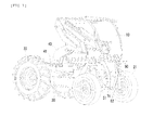
- a driver cab 10 having a driver seat therein is located on a left side portion of a body frame 30 of the tractor, and an articulated arm 40 is disposed on a portion of the body frame 30 where the driver cab 10 is not located, so as to maintain the balance of the tractor.
- the articulated arm 40 is coupled to a rotating shaft 41 so that the articulated arm 40 can be rotated along with the rotating shaft 41.
- the driver cab 10 is disposed between front wheels 21 and rear wheels 22 of the tractor and located on the left side portion of the tractor such that a space is formed beside the driver cab 10. When the articulated arm 40 is not in use, the articulated arm 40 is maintained in a folded state in this space.
- the steering apparatus functions to steer the front wheels 21 of the tractor in the clockwise or counterclockwise direction.
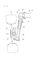
- the steering apparatus is disposed in front of the front wheel axle housing 50 that houses the front wheel axles 53 therein.
- the steering cylinder 71 includes the left and right cylinder rods 72 which are extended and retracted to the left and the right by steering force transmitted by hydraulic pressure when the driver manipulates the steering wheel.
- the steering cylinder 71 is provided in front of the front wheel axle housing 50 at a position spaced apart from the front wheel axle housing 50 by a predetermined distance and is oriented parallel to the front wheel axle housing 50.
- a first link structure which is swung to the left or right by extension or retraction operation of the steering cylinder 71 is provided on a medial portion of the steering apparatus.
- the first link structure comprises a first four-bar link structure which is formed in such a way that ends of the left and right cylinder rods 72 are respectively hinged to swing links 73.
- Second four-bar link structures are formed on left and right sides of the first four-bar link structure. These structures make it possible to steer the front wheels.
- the first four-bar link structure is configured such that first ends of the left and right swing links 73 are hinged to the front wheel axle housing 50 and second ends thereof are respectively hinged to the ends of the left and right cylinder rods 72.
- first ends of the left and right swing links 73 are hinged to the front wheel axle housing 50 and second ends thereof are respectively hinged to the ends of the left and right cylinder rods 72.
- the front wheel axles 53 and the front wheel axle housing 50 are disposed at positions higher than the upper surfaces of the front wheels 21 so that, when the steering apparatus steers the front wheels in the clockwise or counterclockwise direction to maximum angles (70° to 110°), the front wheels 21 can be prevented from being impeded by the front wheel axles 53 or the front wheel axle housing 50 that houses the front wheel axles 53
- a path along which power is transmitted from the front wheel axles 53 to the front wheels 21 has a " " shape.
- Each front wheel 21 includes a wheel frame 21a, over which a tire is fitted.
- a wheel rotating shaft 21b is provided on a central portion of the wheel frame 21a. The wheel rotating shaft 21b is coupled to the rotating member 67 so that the front wheel 21 is rotated by the rotation of the rotating member 67.
- the medial portion of the steering cylinder 71 is fixed to an end of a steering cylinder coupling link 54 which is hinged to a steering cylinder bracket 52 installed on the front wheel axle housing 50.
- the steering cylinder coupling link 54 is hinged to the steering cylinder bracket 52 such that the steering cylinder 71 coupled to the end of the steering cylinder coupling link 54 is prevented from being moved sideways but is allowed to be moved forwards or rearwards by a predetermined distance.
- an inside one (the left wheel of Fig. 7 ) of the front wheels 21 can be turned to 90° or more (in a range of 95° to 105°), and an outside one (the right wheel of Fig. 7 ) can be turned to an angle of less than 90° (in a range of 80° to 89°).
- an inside one (the right wheel of Fig. 8 ) of the front wheels 21 can be turned to 90° or more (in a range of 95° to 105°), and an outside one (the left wheel of Fig. 8 ) can be turned to an angle of less than 90° (in a range of 80° to 89°).
- the angle to which the inner wheel of the front wheels 21 is completely turned is determined by a maximum turning angle to which the outer wheel can be turned.
- the maximum turning angles of the inner wheel and the outer wheel are limited to angles at which the tractor can turn in place with the minimum turning radius.
- the turning angles of the front wheels 21 at which the tractor can turn in place with the minimum turning radius can be determined by width and length of a rectangle defined by the front wheels 21 and the rear wheels 22.
- the maximum turning angle of the inner wheel of the front wheels 21 is limited to a predetermined angle within a range of 95° to 105° with respect to the straight running direction of the tractor
- the maximum turning angle of the outer wheel of the front wheels 21 is limited to a predetermined angle within a range of 80° to 89° with respect to the straight running direction of the tractor.
- the tractor in one place in a desired direction (in the clockwise direction or the counterclockwise direction)
- the driver completely rotates the steering wheel in the desired direction (in the clockwise direction or the counterclockwise direction) and then drives the tractor, the tractor can be turned in one place in the desired direction.
Landscapes
- Engineering & Computer Science (AREA)
- Chemical & Material Sciences (AREA)
- Combustion & Propulsion (AREA)
- Transportation (AREA)
- Mechanical Engineering (AREA)
- Steering-Linkage Mechanisms And Four-Wheel Steering (AREA)
- Guiding Agricultural Machines (AREA)
- Arrangement And Driving Of Transmission Devices (AREA)
- Power Steering Mechanism (AREA)
Applications Claiming Priority (2)
| Application Number | Priority Date | Filing Date | Title |
|---|---|---|---|
| KR1020100098573A KR101029244B1 (ko) | 2010-10-11 | 2010-10-11 | 트랙터의 조향 장치 |
| PCT/KR2011/003781 WO2012050285A1 (fr) | 2010-10-11 | 2011-05-24 | Appareil de direction pour tracteur |
Publications (2)
| Publication Number | Publication Date |
|---|---|
| EP2628660A1 true EP2628660A1 (fr) | 2013-08-21 |
| EP2628660A4 EP2628660A4 (fr) | 2016-04-20 |
Family
ID=44050108
Family Applications (1)
| Application Number | Title | Priority Date | Filing Date |
|---|---|---|---|
| EP11832672.7A Withdrawn EP2628660A4 (fr) | 2010-10-11 | 2011-05-24 | Appareil de direction pour tracteur |
Country Status (6)
| Country | Link |
|---|---|
| US (1) | US8789646B2 (fr) |
| EP (1) | EP2628660A4 (fr) |
| JP (2) | JP2013538750A (fr) |
| KR (1) | KR101029244B1 (fr) |
| CN (1) | CN103167982B (fr) |
| WO (1) | WO2012050285A1 (fr) |
Cited By (3)
| Publication number | Priority date | Publication date | Assignee | Title |
|---|---|---|---|---|
| CN104081905A (zh) * | 2014-07-11 | 2014-10-08 | 焦旗国 | 一种高架结构的农用机底盘 |
| WO2024019236A1 (fr) * | 2022-07-20 | 2024-01-25 | 김중호 | Outil agricole à extension automatique |
| WO2024048853A1 (fr) * | 2022-08-31 | 2024-03-07 | 김중호 | Machine de travail agricole déployable automatiquement et enroulable |
Families Citing this family (13)
| Publication number | Priority date | Publication date | Assignee | Title |
|---|---|---|---|---|
| JP5912974B2 (ja) * | 2012-07-31 | 2016-04-27 | 井関農機株式会社 | 作業車両 |
| JP5884765B2 (ja) * | 2013-03-29 | 2016-03-15 | 井関農機株式会社 | 作業車両 |
| US9828024B2 (en) * | 2013-02-06 | 2017-11-28 | Steering Solutions Ip Holding Corporation | Power steering system |
| CN104842966A (zh) * | 2015-05-26 | 2015-08-19 | 浙江鼎力机械股份有限公司 | 一种高稳定性的高空作业平台的行驶底盘 |
| CN104828755A (zh) * | 2015-05-26 | 2015-08-12 | 浙江鼎力机械股份有限公司 | 一种坑洞保护结构的高空作业平台 |
| US20180290488A1 (en) * | 2017-04-06 | 2018-10-11 | James Kaplan | Dual-direction actuating axle assembly with enhanced durability |
| CN108545112B (zh) * | 2018-05-22 | 2024-03-08 | 长沙桑铼特农业机械设备有限公司 | 一种转向回位装置及拖拉机 |
| KR102116015B1 (ko) * | 2018-06-28 | 2020-05-28 | 주식회사 하다(HADA Co.,Ltd) | 농용 작업차량의 조향장치 |
| CN112628224B (zh) * | 2019-09-24 | 2021-11-19 | 山河智能装备股份有限公司 | 一种四边形连杆机构 |
| GB2591144B (en) * | 2020-01-20 | 2023-12-13 | Bamford Excavators Ltd | An axle assembly |
| CN113273325B (zh) * | 2021-06-19 | 2022-03-25 | 鹤壁职业技术学院 | 一种小型智能耕地机 |
| DE102021213066B4 (de) * | 2021-11-22 | 2025-07-03 | Zf Friedrichshafen Ag | Lenkachse für ein lenkbares Fahrzeug und Flurförderzeug |
| CN114184238B (zh) * | 2021-12-30 | 2024-06-28 | 杭州电子科技大学 | 一种可转向和减震的老旧管道巡检机器人 |
Family Cites Families (21)
| Publication number | Priority date | Publication date | Assignee | Title |
|---|---|---|---|---|
| US4064967A (en) * | 1976-07-23 | 1977-12-27 | Clark Equipment Company | Steering mechanism |
| DE3245085A1 (de) * | 1982-12-06 | 1984-06-07 | Kramer-Werke GmbH, 7770 Überlingen | Fahrbares arbeitsgeraet |
| KR840004009A (ko) * | 1983-03-15 | 1984-10-06 | 신일현 | 소형 다목적 트렉터 |
| JPS6223804A (ja) * | 1985-07-23 | 1987-01-31 | Toyoda Autom Loom Works Ltd | 高所作業車における懸架装置 |
| JPH068110B2 (ja) * | 1987-04-13 | 1994-02-02 | 株式会社クボタ | パワ−ステアリング装置 |
| JPH0338472A (ja) * | 1989-07-05 | 1991-02-19 | Iseki & Co Ltd | 動力農機のスピン旋回装置 |
| JPH0426615A (ja) * | 1990-05-19 | 1992-01-29 | Kamiyama Kenichi | アルカリ入りハミガキ |
| JPH0532101A (ja) * | 1991-07-31 | 1993-02-09 | Iseki & Co Ltd | 移動車両のトレツド調節容易化装置 |
| JPH08318750A (ja) * | 1995-05-23 | 1996-12-03 | Yanmar Agricult Equip Co Ltd | 乗用管理作業車 |
| JPH09226615A (ja) * | 1996-02-29 | 1997-09-02 | Nosakubutsu Seiiku Kanri Syst Kenkyusho:Kk | 農用作業車 |
| JPH10158000A (ja) * | 1996-11-29 | 1998-06-16 | Aichi Corp | ステアリング装置 |
| JP2004130970A (ja) * | 2002-10-11 | 2004-04-30 | Mitsubishi Agricult Mach Co Ltd | 作業車両のパワーステアリング装置 |
| ATE487634T1 (de) * | 2003-01-08 | 2010-11-15 | Kanzaki Kokyukoki Mfg Co Ltd | Hydraulische achsenantriebsvorrichtung |
| JP4195322B2 (ja) * | 2003-03-24 | 2008-12-10 | 株式会社ショーシン | 農業用車輌 |
| JP4156444B2 (ja) * | 2003-06-02 | 2008-09-24 | 株式会社 神崎高級工機製作所 | 油圧式操舵機構 |
| DE102004053722B4 (de) * | 2004-11-06 | 2020-02-20 | Zf Friedrichshafen Ag | Fahrzeug mit wenigstens einer über eine Achsschenkellenkung lenkbar ausgeführten Fahrzeugachse |
| DE102005046895A1 (de) * | 2005-09-30 | 2007-05-03 | Zf Friedrichshafen Ag | Achsschenkellenkvorrichtung eines Fahrzeugs |
| CN200942801Y (zh) * | 2006-09-01 | 2007-09-05 | 李鹏 | 拖拉机液压助力转向机构 |
| CN201012706Y (zh) * | 2006-10-20 | 2008-01-30 | 上海汇金汽车拖拉机零部件有限公司 | 拖拉机前驱动桥中液压转向油缸的位置结构 |
| US7854293B2 (en) * | 2007-02-20 | 2010-12-21 | Textron Innovations Inc. | Steering operated by linear electric device |
| JP5267501B2 (ja) * | 2010-05-10 | 2013-08-21 | 井関農機株式会社 | 乗用型作業機 |
-
2010
- 2010-10-11 KR KR1020100098573A patent/KR101029244B1/ko not_active Expired - Fee Related
-
2011
- 2011-05-24 CN CN201180048635.3A patent/CN103167982B/zh not_active Expired - Fee Related
- 2011-05-24 JP JP2013532706A patent/JP2013538750A/ja active Pending
- 2011-05-24 US US13/878,048 patent/US8789646B2/en active Active
- 2011-05-24 WO PCT/KR2011/003781 patent/WO2012050285A1/fr not_active Ceased
- 2011-05-24 EP EP11832672.7A patent/EP2628660A4/fr not_active Withdrawn
-
2014
- 2014-12-01 JP JP2014243447A patent/JP2015042548A/ja active Pending
Cited By (4)
| Publication number | Priority date | Publication date | Assignee | Title |
|---|---|---|---|---|
| CN104081905A (zh) * | 2014-07-11 | 2014-10-08 | 焦旗国 | 一种高架结构的农用机底盘 |
| CN104081905B (zh) * | 2014-07-11 | 2016-06-29 | 焦旗国 | 一种高架结构的农用机底盘 |
| WO2024019236A1 (fr) * | 2022-07-20 | 2024-01-25 | 김중호 | Outil agricole à extension automatique |
| WO2024048853A1 (fr) * | 2022-08-31 | 2024-03-07 | 김중호 | Machine de travail agricole déployable automatiquement et enroulable |
Also Published As
| Publication number | Publication date |
|---|---|
| WO2012050285A1 (fr) | 2012-04-19 |
| CN103167982A (zh) | 2013-06-19 |
| CN103167982B (zh) | 2017-02-08 |
| KR101029244B1 (ko) | 2011-04-19 |
| JP2013538750A (ja) | 2013-10-17 |
| US20130192920A1 (en) | 2013-08-01 |
| EP2628660A4 (fr) | 2016-04-20 |
| US8789646B2 (en) | 2014-07-29 |
| JP2015042548A (ja) | 2015-03-05 |
Similar Documents
| Publication | Publication Date | Title |
|---|---|---|
| US8789646B2 (en) | Steering apparatus of for a tractor | |
| US8910741B2 (en) | Steering device for tractor | |
| US10703409B2 (en) | Work vehicle axle device | |
| CA2618175C (fr) | Orientation pour outils tractes | |
| AU2003284858B2 (en) | A trailer for towing after a towing vehicle, a system comprising a trailer and a towing vehicle, and a method of steering a trailer around a turning point | |
| JPH0211447B2 (fr) | ||
| US9381805B2 (en) | Tractor | |
| US8978810B2 (en) | Tractor | |
| US7758058B2 (en) | Front Steerable device for a vehicle | |
| EP3053770B1 (fr) | Véhicule de travail | |
| US11772702B2 (en) | Steering knuckle gearbox assembly | |
| US9701522B2 (en) | Work vehicle | |
| EP3199427B1 (fr) | Véhicule de travail | |
| KR101195206B1 (ko) | 트랙터 | |
| EP1547906A1 (fr) | Disposition de suspension | |
| CA3073006A1 (fr) | Ensemble boite de vitesses a porte-fusee de direction | |
| GB2420065A (en) | Articulated arm for agricultural tools |
Legal Events
| Date | Code | Title | Description |
|---|---|---|---|
| PUAI | Public reference made under article 153(3) epc to a published international application that has entered the european phase |
Free format text: ORIGINAL CODE: 0009012 |
|
| 17P | Request for examination filed |
Effective date: 20130315 |
|
| AK | Designated contracting states |
Kind code of ref document: A1 Designated state(s): AL AT BE BG CH CY CZ DE DK EE ES FI FR GB GR HR HU IE IS IT LI LT LU LV MC MK MT NL NO PL PT RO RS SE SI SK SM TR |
|
| DAX | Request for extension of the european patent (deleted) | ||
| RA4 | Supplementary search report drawn up and despatched (corrected) |
Effective date: 20160318 |
|
| RIC1 | Information provided on ipc code assigned before grant |
Ipc: B62D 7/20 20060101ALI20160314BHEP Ipc: A01B 69/00 20060101AFI20160314BHEP Ipc: B62D 7/18 20060101ALI20160314BHEP Ipc: B62D 7/06 20060101ALN20160314BHEP Ipc: B62D 9/00 20060101ALI20160314BHEP Ipc: B60K 17/30 20060101ALI20160314BHEP |
|
| STAA | Information on the status of an ep patent application or granted ep patent |
Free format text: STATUS: THE APPLICATION IS DEEMED TO BE WITHDRAWN |
|
| 18D | Application deemed to be withdrawn |
Effective date: 20161018 |