EP2629077A2 - Abgas Probenentnahme System - Google Patents
Abgas Probenentnahme System Download PDFInfo
- Publication number
- EP2629077A2 EP2629077A2 EP13000741.2A EP13000741A EP2629077A2 EP 2629077 A2 EP2629077 A2 EP 2629077A2 EP 13000741 A EP13000741 A EP 13000741A EP 2629077 A2 EP2629077 A2 EP 2629077A2
- Authority
- EP
- European Patent Office
- Prior art keywords
- exhaust gas
- temperature
- heating
- sampling
- sampling line
- Prior art date
- Legal status (The legal status is an assumption and is not a legal conclusion. Google has not performed a legal analysis and makes no representation as to the accuracy of the status listed.)
- Withdrawn
Links
Images


Classifications
-
- G—PHYSICS
- G01—MEASURING; TESTING
- G01N—INVESTIGATING OR ANALYSING MATERIALS BY DETERMINING THEIR CHEMICAL OR PHYSICAL PROPERTIES
- G01N1/00—Sampling; Preparing specimens for investigation
- G01N1/02—Devices for withdrawing samples
- G01N1/22—Devices for withdrawing samples in the gaseous state
- G01N1/2247—Sampling from a flowing stream of gas
-
- G—PHYSICS
- G01—MEASURING; TESTING
- G01N—INVESTIGATING OR ANALYSING MATERIALS BY DETERMINING THEIR CHEMICAL OR PHYSICAL PROPERTIES
- G01N1/00—Sampling; Preparing specimens for investigation
- G01N1/02—Devices for withdrawing samples
- G01N1/22—Devices for withdrawing samples in the gaseous state
- G01N1/2247—Sampling from a flowing stream of gas
- G01N1/2258—Sampling from a flowing stream of gas in a stack or chimney
-
- F—MECHANICAL ENGINEERING; LIGHTING; HEATING; WEAPONS; BLASTING
- F01—MACHINES OR ENGINES IN GENERAL; ENGINE PLANTS IN GENERAL; STEAM ENGINES
- F01N—GAS-FLOW SILENCERS OR EXHAUST APPARATUS FOR MACHINES OR ENGINES IN GENERAL; GAS-FLOW SILENCERS OR EXHAUST APPARATUS FOR INTERNAL-COMBUSTION ENGINES
- F01N3/00—Exhaust or silencing apparatus having means for purifying, rendering innocuous, or otherwise treating exhaust
- F01N3/08—Exhaust or silencing apparatus having means for purifying, rendering innocuous, or otherwise treating exhaust for rendering innocuous
- F01N3/10—Exhaust or silencing apparatus having means for purifying, rendering innocuous, or otherwise treating exhaust for rendering innocuous by thermal or catalytic conversion of noxious components of exhaust
- F01N3/18—Exhaust or silencing apparatus having means for purifying, rendering innocuous, or otherwise treating exhaust for rendering innocuous by thermal or catalytic conversion of noxious components of exhaust characterised by methods of operation; Control
- F01N3/20—Exhaust or silencing apparatus having means for purifying, rendering innocuous, or otherwise treating exhaust for rendering innocuous by thermal or catalytic conversion of noxious components of exhaust characterised by methods of operation; Control specially adapted for catalytic conversion
- F01N3/206—Adding periodically or continuously substances to exhaust gases for promoting purification, e.g. catalytic material in liquid form, NOx reducing agents
- F01N3/2066—Selective catalytic reduction [SCR]
-
- F—MECHANICAL ENGINEERING; LIGHTING; HEATING; WEAPONS; BLASTING
- F01—MACHINES OR ENGINES IN GENERAL; ENGINE PLANTS IN GENERAL; STEAM ENGINES
- F01N—GAS-FLOW SILENCERS OR EXHAUST APPARATUS FOR MACHINES OR ENGINES IN GENERAL; GAS-FLOW SILENCERS OR EXHAUST APPARATUS FOR INTERNAL-COMBUSTION ENGINES
- F01N3/00—Exhaust or silencing apparatus having means for purifying, rendering innocuous, or otherwise treating exhaust
- F01N3/08—Exhaust or silencing apparatus having means for purifying, rendering innocuous, or otherwise treating exhaust for rendering innocuous
- F01N3/10—Exhaust or silencing apparatus having means for purifying, rendering innocuous, or otherwise treating exhaust for rendering innocuous by thermal or catalytic conversion of noxious components of exhaust
- F01N3/18—Exhaust or silencing apparatus having means for purifying, rendering innocuous, or otherwise treating exhaust for rendering innocuous by thermal or catalytic conversion of noxious components of exhaust characterised by methods of operation; Control
- F01N3/20—Exhaust or silencing apparatus having means for purifying, rendering innocuous, or otherwise treating exhaust for rendering innocuous by thermal or catalytic conversion of noxious components of exhaust characterised by methods of operation; Control specially adapted for catalytic conversion
- F01N3/206—Adding periodically or continuously substances to exhaust gases for promoting purification, e.g. catalytic material in liquid form, NOx reducing agents
- F01N3/208—Control of selective catalytic reduction [SCR], e.g. by adjusting the dosing of reducing agent
-
- F—MECHANICAL ENGINEERING; LIGHTING; HEATING; WEAPONS; BLASTING
- F01—MACHINES OR ENGINES IN GENERAL; ENGINE PLANTS IN GENERAL; STEAM ENGINES
- F01N—GAS-FLOW SILENCERS OR EXHAUST APPARATUS FOR MACHINES OR ENGINES IN GENERAL; GAS-FLOW SILENCERS OR EXHAUST APPARATUS FOR INTERNAL-COMBUSTION ENGINES
- F01N2610/00—Adding substances to exhaust gases
- F01N2610/02—Adding substances to exhaust gases the substance being ammonia or urea
-
- F—MECHANICAL ENGINEERING; LIGHTING; HEATING; WEAPONS; BLASTING
- F01—MACHINES OR ENGINES IN GENERAL; ENGINE PLANTS IN GENERAL; STEAM ENGINES
- F01N—GAS-FLOW SILENCERS OR EXHAUST APPARATUS FOR MACHINES OR ENGINES IN GENERAL; GAS-FLOW SILENCERS OR EXHAUST APPARATUS FOR INTERNAL-COMBUSTION ENGINES
- F01N2900/00—Details of electrical control or of the monitoring of the exhaust gas treating apparatus
- F01N2900/04—Methods of control or diagnosing
- F01N2900/0416—Methods of control or diagnosing using the state of a sensor, e.g. of an exhaust gas sensor
-
- F—MECHANICAL ENGINEERING; LIGHTING; HEATING; WEAPONS; BLASTING
- F01—MACHINES OR ENGINES IN GENERAL; ENGINE PLANTS IN GENERAL; STEAM ENGINES
- F01N—GAS-FLOW SILENCERS OR EXHAUST APPARATUS FOR MACHINES OR ENGINES IN GENERAL; GAS-FLOW SILENCERS OR EXHAUST APPARATUS FOR INTERNAL-COMBUSTION ENGINES
- F01N2900/00—Details of electrical control or of the monitoring of the exhaust gas treating apparatus
- F01N2900/06—Parameters used for exhaust control or diagnosing
- F01N2900/14—Parameters used for exhaust control or diagnosing said parameters being related to the exhaust gas
- F01N2900/1402—Exhaust gas composition
-
- G—PHYSICS
- G01—MEASURING; TESTING
- G01N—INVESTIGATING OR ANALYSING MATERIALS BY DETERMINING THEIR CHEMICAL OR PHYSICAL PROPERTIES
- G01N1/00—Sampling; Preparing specimens for investigation
- G01N1/02—Devices for withdrawing samples
- G01N1/22—Devices for withdrawing samples in the gaseous state
- G01N1/2247—Sampling from a flowing stream of gas
- G01N1/2258—Sampling from a flowing stream of gas in a stack or chimney
- G01N2001/2261—Sampling from a flowing stream of gas in a stack or chimney preventing condensation (heating lines)
-
- Y—GENERAL TAGGING OF NEW TECHNOLOGICAL DEVELOPMENTS; GENERAL TAGGING OF CROSS-SECTIONAL TECHNOLOGIES SPANNING OVER SEVERAL SECTIONS OF THE IPC; TECHNICAL SUBJECTS COVERED BY FORMER USPC CROSS-REFERENCE ART COLLECTIONS [XRACs] AND DIGESTS
- Y02—TECHNOLOGIES OR APPLICATIONS FOR MITIGATION OR ADAPTATION AGAINST CLIMATE CHANGE
- Y02T—CLIMATE CHANGE MITIGATION TECHNOLOGIES RELATED TO TRANSPORTATION
- Y02T10/00—Road transport of goods or passengers
- Y02T10/10—Internal combustion engine [ICE] based vehicles
- Y02T10/12—Improving ICE efficiencies
Definitions
- the present invention relates to an exhaust gas sampling device for sampling exhaust gas from an exhaust pipe in which exhaust gas flows and introducing the sampling gas into an analyzing instrument.
- urea SCR system As a system for reducing NOx contained in engine exhaust gas discharged from a diesel engine.
- This urea SCR system is configured to arrange a SCR catalyst in an exhaust pipe so that urea ((NH 2 ) 2 CO) is injected to the upstream side of the corresponding SCR catalyst.
- the urea injected into the exhaust pipe produces NH 3 due to a thermal decomposition reaction of (NH 2 ) 2 CO + H 2 O ⁇ 2NH 3 + CO 2 . Then, this NH 3 reacts with NO x by the SCR catalyst so that NO x is reduced to be N 2 . In specific, there occurs a reduction reaction of 4NH 3 + 4NO + O 2 ⁇ 4N 2 +6 H 2 O, 4NH 3 + 2 NO 2 + O 2 ⁇ 3N 2 +6 H 2 O in the SCR catalysis.
- the conventional exhaust gas measurement system includes a sampling line for sampling the exhaust gas from the downstream side of the SCR catalysis and an NH 3 analyzer for measuring a concentration of ammonia contained in the exhaust gas sampled by the corresponding sampling line, whereby it is checked based on the concentration of ammonia obtained by the NH 3 meter whether or not the injection amount of urea is optimum.
- the temperature of the exhaust gas flowing through the exhaust pipe is changed to various temperatures (for example, 100 °C to 500 °C) according to operation conditions of the engine, and the urea injected to the exhaust pipe is passed through the SCR catalysis without sufficiently performing the thermal decomposition and hydrolysis thereof in some cases. Therefore, although the urea is to be contained in the sampled exhaust gas, if ammonia is produced without sufficient thermal decomposition and hydrolysis of the urea, a proper injection amount of urea cannot be decided to be problematic.
- the sampling line in order not to absorb ammonia to the sampling line, or in order to prevent condensation of a predetermined component contained in the exhaust gas, the sampling line is heated or cooled to be a predetermined constant temperature in some cases.
- the sampling line is heated to a constant temperature for preventing the absorption and condensation
- a measurement temperature of an analyzing instrument connected to the sampling line or such as a setting temperature of such as a filter and an orifice provided in the sampling line due to limitations of a measurement temperature of an analyzing instrument connected to the sampling line or such as a setting temperature of such as a filter and an orifice provided in the sampling line, a predetermined component such as urea contained in the exhaust gas cannot be heated or cooled to the temperatures required for thermal decomposition or hydrolysis to be problematic.
- Patent Literature 1 JP2010-236877A
- the present invention has its essential object to make it possible to heat or cool a temperature of sampled exhaust gas flowing through a sampling line to be a desired temperature in accordance with such as various exhaust gas conditions and usage conditions of the sampling line irrespective of a temperature of the exhaust gas flowing through an exhaust pipe.
- an exhaust gas sampling device includes: a sampling line for sampling the exhaust gas flowing through an exhaust pipe to be introduced into an analyzing instrument; a plurality of heating parts provided along the sampling line from an upstream side to a downstream side for heating the exhaust gas flowing through the sampling line; and a temperature control part for individually defining setting temperatures of the plurality of heating parts using the temperature of the exhaust gas in the exhaust pipe and a target temperature of the exhaust gas in an outlet side of the heating part located in the most downstream among the plurality of heating parts as parameters.
- the exhaust gas temperature can be controlled to be an exhaust gas target temperature in the outlet side of the heating part located in the most downstream so that the exhaust gas temperature can be adjusted in accordance with the usage conditions and the like of the sampling line.
- the exhaust gas can be heated or cooled to an exhaust gas target temperature by defining the setting temperature to be the exhaust gas target temperature.
- first temperature a predetermined temperature
- second temperature a predetermined temperature
- a single temperature gradient is formed using one heating part by controlling a winding density of a heater coil and the like to thereby heat or cool the exhaust gas to a target temperature
- the temperature gradient is single, the temperature to be heated or cooled by the heating part in accordance with the temperature of the exhaust gas flowing into the heating part is determined, and therefore it is difficult to obtain a desired temperature in some cases.
- the temperature control part defines the setting temperature of the heating part located in the most upstream to be a temperature higher than the exhaust target temperature.
- the exhaust gas temperature is once adjusted to be a temperature higher than the exhaust gas target temperature so that the decomposition reaction of the predetermined components contained in the exhaust gas is allowed to proceed sufficiently and then the exhaust gas can be introduced into such as an analyzing instrument.
- the exhaust gas includes urea and/or a decomposition component derived from urea
- the setting temperature of the heating part located in the most upstream is a temperature equal to or higher than a hydrolysis temperature of isocyanate produced by thermal decomposition of the urea.
- cyanuric acid may be possibly produced by thermal decomposition of urea under some temperature rise conditions of urea.
- the setting temperature of the heating part located in the most upstream is a temperature equal to or higher than a decomposition temperature of decomposing cyanuric acid produced by thermal decomposition of the urea into isocyanate.
- the sampling line is provided with an adiabatic expansion part for adiabatically expanding the exhaust gas flowing through the corresponding sampling line
- the plurality of heating parts are provided in an upstream side than the adiabatic expansion part
- the adiabatic expansion part includes a throttle part for decompressing the exhaust gas flowing through the sampling line and a temperature adjustment part for adjusting a temperature of the exhaust gas that has passed through the corresponding throttle part
- the temperature control part individually defines the setting temperatures of the plurality of heating parts using the exhaust gas temperature and the exhaust gas target temperature at the throttle part as the parameters.
- the throttle part and the temperature adjustment part By decompressing and heating the exhaust gas by the throttle part and the temperature adjustment part in this way, condensation of a predetermined component (for example, hydrocarbon) contained in the exhaust gas that has passed through the throttle part can be prevented.
- the target exhaust gas temperature at the throttle part is defined to be, for example, that of the analyzing instrument having the highest usage temperature among the plurality of analyzing instruments, whereby the exhaust gas sampling device of the present invention can be used for the plurality of analyzing instruments.
- the exhaust gas can be introduced into a predetermined analyzing instrument with the temperature thereof made lower than the target exhaust gas temperature at the throttle part.
- the exhaust gas sampling device of the present invention is used in a measurement system of hydrocarbon, there is a problem that the corresponding hydrocarbon is condensed so that ammonia would be adsorbed to the corresponding hydrocarbon. Therefore, it is desirable that the exhaust gas target temperature at the throttle part is a temperature higher than a condensation temperature of HC contained in the exhaust gas. Further, since the exhaust gas is expanded by the adiabatic expansion part, the exhaust gas temperature can be lowered to a measurement temperature of the NH 3 analyzer while the condensation of the hydrocarbon is prevented.
- the present invention configured as described above, since it is possible to heat or cool the sampled exhaust gas flowing through a sampling line to a desired temperature irrespective of a temperature of the exhaust gas flowing through an exhaust pipe and various temperature gradients can be formed by individually defining the setting temperatures of the plurality of heating parts, it is possible to provide an exhaust gas sampling device that can be used in various applications capable of providing such as a decomposition a predetermined component contained in the exhaust gas can be sufficiently proceeded.
- the exhaust gas measurement system of the present embodiment is intended to measure a predetermined component contained in the exhaust gas discharged from an internal combustion engine such as, for example, a diesel engine.
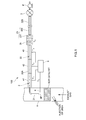
- this exhaust gas measurement system includes: a sampling line 2 which is equipped with a sampling port SP inside an exhaust pipe H to introduce the exhaust gas taken by the corresponding sampling port SP into an analyzing instrument 3; a plurality of heating parts 41 to 43 (three in the present embodiment) provided along the corresponding sampling line 2 from an upstream side to a downstream side for heating the exhaust gas flowing through the sampling line 2; and a temperature control part 5 for individually defining setting temperatures of the respective plurality of heating parts 41 to 43 using an exhaust gas temperature T G (a temperature of the exhaust gas at a sampling point (in the vicinity of the sampling port SP)) in the exhaust pipe H and an exhaust gas target temperature T A at an outlet side of the heating part 43 located in the most downstream among the plurality of heating parts 41 to 43 as parameters.
- T G a temperature of the exhaust gas at a sampling point (in the vicinity of the sampling port SP)
- the analyzing instrument 3 of the present embodiment is an NH 3 analyzer for measuring a concentration of ammonia contained in the exhaust gas by an absorptiometric method using a laser beam.
- the NH 3 analyzer is provided with: a measuring cell; a laser beam irradiation part for introducing a laser beam through a light introduction window of this measuring cell and irradiating a laser beam with high linearity to the sample gas in the measuring cell; a light detecting part that detects the laser beam transmitted out of the measuring cell; and a decompression pump (pump P located in a downstream side of the sampling line 2) connected to the measuring cell to decompresses inside the measuring cell.
- a decompression pump pump P located in a downstream side of the sampling line 2
- the laser beam irradiation part is intended to emit a laser beam having a wavelength of an infrared region such as a middle infrared region or a near-infrared region or an oscillation wavelength of an ultraviolet region in which the NH 3 has absorption characteristics and it is considered to use, for example, a quantum cascade laser, a semiconductor laser such as a wavelength tunable semiconductor laser, a solid laser or a liquid laser.
- the light detection part it is considered to use, for example, MCT (HgCdTe) detector of a room temperature operation type.
- the decompression pump decompresses inside the measuring cell, for example, to 1 kPa (a pressure at which the gas concentration becomes too small so that the measurement becomes difficult) to 50 kPa (a pressure at which a peak becomes gentle and becomes easy to occur interference with the other gas components), and preferably decompresses to 20 kPa to 30 kPa which is in a pressure range where the absorption of NH 3 is less likely to occur, and there occurs no interference with further another gas component while achieving a measurable gas concentration.
- 1 kPa a pressure at which the gas concentration becomes too small so that the measurement becomes difficult
- 50 kPa a pressure at which a peak becomes gentle and becomes easy to occur interference with the other gas components
- the sampling line 2 includes: a sampling unit 21 which is provided inside the exhaust pipe H to take a part of the exhaust gas flowing through the exhaust pipe H by a sampling port SP; and a sampling piping 22 which is connected to the sampling unit 21 to introduce the sampled exhaust gas into the analyzing instrument 3.
- the sampling piping 22 is provided with a throttle part (for example, an orifice) 231 that constitutes an adiabatic expansion part 23 for adiabatically expanding the sampled exhaust gas to be decompressed and cooled. There is further provided a filter 24 in the immediate vicinity of the upstream side of the throttle part 231 for removing soot and the like in the exhaust gas. And the sampling piping 22 is divided into an upstream side piping 22A located in the upstream side of the throttle part 231 and the filter 24 and a downstream side piping 22B located in the downstream side of the throttle part 231 and the filter 24.
- a throttle part for example, an orifice
- a filter 24 in the immediate vicinity of the upstream side of the throttle part 231 for removing soot and the like in the exhaust gas.
- the sampling piping 22 is divided into an upstream side piping 22A located in the upstream side of the throttle part 231 and the filter 24 and a downstream side piping 22B located in the downstream side of the throttle part 231 and the filter
- a plurality of heating parts 41 to 43 are provided on the upstream side piping 22A, and a temperature adjustment part 232 such as a heating pipe constituting the adiabatic expansion part 23 is provided on the downstream side piping 22B for keeping the downstream side piping 22B at a constant temperature (113 °C which is the usage temperature of the NH 3 analyzer 3 in the present embodiment).
- a temperature adjustment part 232 such as a heating pipe constituting the adiabatic expansion part 23 is provided on the downstream side piping 22B for keeping the downstream side piping 22B at a constant temperature (113 °C which is the usage temperature of the NH 3 analyzer 3 in the present embodiment).
- the plurality of heating parts 41 to 43 are provided on the upstream side piping 22A located in the upstream side of the throttle part 231 and the filter 24.
- Each of the heating parts 41 to 43 is a coil shaped or cylindrical shaped heater provided on the outer surface of the upstream side piping 22A, and this heater is adjusted to be a predetermined temperature by controlling a current value of current supplied by a temperature control part 5 to be described later.
- the plurality of heating parts 41 to 43 are provided over the whole part of the upstream side piping 22A, and each of the heating parts 41 to 43 is entirely provided over each of the multiple regions obtained by equally dividing the upstream side piping 22A.
- the temperature control part 5 is composed of such as a PID controller, which is provided in the vicinity of the sampling port SP inside the exhaust pipe H so that an exhaust gas temperature T G is acquired from a temperature sensor 6 for detecting the exhaust gas temperature T G at the corresponding sampling point.
- a predetermined exhaust gas target temperature T A at an outlet side of the heating part 43 located in the most downstream is inputted.
- the exhaust gas target temperature T A is an exhaust gas target temperature of the exhaust gas flowing into the adiabatic expansion part 23 and this exhaust gas target temperature is 190 °C which is higher than the condensation temperature of the hydrocarbon (HC) contained in the exhaust gas.
- the temperature control part 5 individually defines the setting temperatures T 1 to T 3 of the plurality of heating parts 41 to 43, respectively, using the exhaust gas temperature T G and the exhaust gas target temperature T A as parameters and then controls the current flowing through the respective heating parts 41 to 43 so that the heating temperatures of the respective heating parts 41 to 43 made equal to the setting temperatures T 1 to T 3 .
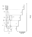
- the temperature control part 5 defines the temperatures obtained by equally dividing the difference between the exhaust gas temperature T G and the exhaust gas target temperature T A to be used as the setting temperatures T 1 to T 3 of the respective heating parts 41 to 43.
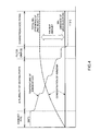
- This temperature 300 °C is the decomposition temperature of decomposing cyanuric acid produced by thermal decomposition of urea to isocyanate.
- the setting temperature of the heating part 41 located in the most upstream is defined to be equal to or higher than the decomposition temperature, the amount of ammonia produced from the urea can be increased as much as possible so that the measurement accuracy of the concentration of ammonia can be improved.
- the temperature control part 5 defines the temperatures obtained by equally dividing the difference between the setting temperature T 1 and the exhaust gas target temperature T A to be used as the setting temperatures T 2 and T 3 of the respective second and third heating parts 42 and 43.
- the setting temperatures T 1 to T 3 of the plurality of heating parts 41 to 43 are defined in such a manner that, the temperature of the exhaust gas is changed in the temperature range including the whole temperatures of: the thermal decomposition temperature (132 °C) of urea; hydrolysis temperature (160 °C) of isocyanate produced by thermal decomposition of urea; and thermal decomposition temperature (equal to or higher than 300 °C) of cyanuric acid produced by thermal decomposition of urea, until the exhaust gas temperature T G is heated or cooled to the exhaust gas target temperature T A .
- the setting temperatures T 1 to T 3 of the first to third heating parts 41 to 43 may be defined to be equal to the exhaust gas target temperature T A (190 °C) so that the temperature of the sampled exhaust gas that has passed through the upstream side piping 22A of the sampling line 2 becomes the exhaust gas target temperature T A .
- the concentration of the NH 3 obtained by the NH 3 analyzer 3 is a concentration of raw NH 3 originally contained in the exhaust gas discharged from the internal combustion engine. Since ammonia is not thermally decomposed even though heated in the sampling line, in the case where there is no absorption or the like of ammonia to an inner surface of the sampling line, the concentration of the NH 3 contained in the exhaust gas flowing through the exhaust pipe is equal to the concentration of the NH 3 obtained by the NH 3 analyzer 3.
- the concentration of the NH 3 obtained by the NH 3 analyzer 3 is equal to a concentration of the NH 3 obtained by adding excessive NH 3 which could not have been reacted with NO x by a SCR catalyst and NH 3 produced by thermal decomposition and hydrolysis of the urea contained in the sampled exhaust gas in addition to the concentration of the raw NH 3 .
- the concentration of NH 3 caused by an urea SCR can be calculated based on a difference between the concentrations of the NH 3 obtained by these two measurements so that the evaluation of the urea SCR system can be properly performed.
- the plurality of heating parts 41 to 43 are provided along the sampling line 2 and the setting temperatures of the plurality of heating parts 41 to 43 are individually defined using the temperature T G of the exhaust gas in the exhaust pipe H and a target temperature T A of the exhaust gas in the outlet side of the heating part 43 located in the most downstream as parameters, it is possible to heat or cool a temperature of sampled exhaust gas flowing through the sampling line 2 to be a desired temperature irrespective of a temperature of the exhaust gas flowing through the exhaust pipe H.
- the sampling line it is possible to form various temperature gradients along the sampling line from the upstream side to the downstream side, for example, a temperature gradient falling down from the upstream side to the downstream side, a temperature gradient rising up from the upstream side to the downstream side, a mountain like sloped temperature gradient and the like by the plurality of heating parts 41 to 43.
- the exhaust gas temperature T G can be controlled to be an exhaust gas target temperature T A so that the exhaust gas temperature T G can be adjusted in accordance with the usage conditions and the like of the filter 24, adiabatic expansion part 23 or the analyzing instrument 3 etc. provided on the sampling line 2.
- the isocyanate (HNCO) produced by thermal decomposition of urea can be hydrolyzed in the sampling line 2 but also the cyanuric acid produced by thermal decomposition of urea can be thermally decomposed to isocyanate and the corresponding isocyanate can be hydrolyzed in the sampling line 2, the concentration of ammonia derived from urea can be accurately measured.
- the gas pressure inside the measuring cell and in the flow passage from the downstream side of the throttle part 231 to the measuring cell are decompressed by the pump P, a region to be decompressed in the flow passage connected to the measuring cell can be enlarged and the absorption of absorptive gas components such as NH 3 or HC can be reduced.
- the decompressed sampling gas is to be heated by the temperature adjustment part 232 and therefore a loss of dissolved gas of the absorptive gas components caused along with condensation inside the pipe can be prevented so that the measurement accuracy and the response speed can be further improved.
- the exhaust sampling device 100 includes the adiabatic expansion part 23 in order to be commonly used for a plurality of components (such as HC and NH 3 ) to be measured in the above embodiment
- the sampled exhaust gas may be directly introduced into the analyzing instrument 3 without the adiabatic expansion part 23 as shown in Fig. 5 .
- the exhaust gas target temperature is, e.g., 113 °C because the analyzing instrument is composed of an NH 3 analyzer as in the above embodiment.
- the exhaust gas measurement system includes the NH 3 analyzer in the above embodiment
- a plurality of other analyzers for measuring various components contained in the exhaust gas may be included in the exhaust gas measuring system.
- the plurality of analyzers may be arranged in series on the sampling line 2, or the downstream side pipe of the sampling line 2 may be branched into a plurality of flow passages so that each of the analyzers is arranged on each of the branched flow passages.
Landscapes
- Engineering & Computer Science (AREA)
- Chemical & Material Sciences (AREA)
- Health & Medical Sciences (AREA)
- Chemical Kinetics & Catalysis (AREA)
- Life Sciences & Earth Sciences (AREA)
- General Engineering & Computer Science (AREA)
- Mechanical Engineering (AREA)
- Combustion & Propulsion (AREA)
- Toxicology (AREA)
- Physics & Mathematics (AREA)
- General Physics & Mathematics (AREA)
- Immunology (AREA)
- Pathology (AREA)
- General Health & Medical Sciences (AREA)
- Biochemistry (AREA)
- Analytical Chemistry (AREA)
- Molecular Biology (AREA)
- Biomedical Technology (AREA)
- Sampling And Sample Adjustment (AREA)
- Investigating Or Analyzing Non-Biological Materials By The Use Of Chemical Means (AREA)
Applications Claiming Priority (1)
| Application Number | Priority Date | Filing Date | Title |
|---|---|---|---|
| JP2012029921A JP5752067B2 (ja) | 2012-02-14 | 2012-02-14 | 排ガスサンプリング装置 |
Publications (2)
| Publication Number | Publication Date |
|---|---|
| EP2629077A2 true EP2629077A2 (de) | 2013-08-21 |
| EP2629077A3 EP2629077A3 (de) | 2017-12-27 |
Family
ID=47738986
Family Applications (1)
| Application Number | Title | Priority Date | Filing Date |
|---|---|---|---|
| EP13000741.2A Withdrawn EP2629077A3 (de) | 2012-02-14 | 2013-02-13 | Abgasproben-Entnahmesystem |
Country Status (5)
| Country | Link |
|---|---|
| US (1) | US9335235B2 (de) |
| EP (1) | EP2629077A3 (de) |
| JP (1) | JP5752067B2 (de) |
| CN (1) | CN103245535A (de) |
| IN (1) | IN2013CH00582A (de) |
Families Citing this family (12)
| Publication number | Priority date | Publication date | Assignee | Title |
|---|---|---|---|---|
| CN104374610B (zh) * | 2014-11-14 | 2017-01-11 | 华能国际电力股份有限公司 | 一种尿素水解反应器的气相分离取样系统及取样方法 |
| CN104458349A (zh) * | 2014-12-01 | 2015-03-25 | 安徽天德仪器科技有限公司 | 防爆一体化电加热气体取样装置 |
| KR101661064B1 (ko) * | 2015-04-20 | 2016-09-30 | 한국기술교육대학교 산학협력단 | 써멀 디뉴더, 이를 가지는 블랙카본입자 측정시스템 및 측정방법 |
| US9500580B1 (en) | 2015-06-04 | 2016-11-22 | General Electric Company | Gas detector and method of detection |
| CN107631916A (zh) * | 2017-09-12 | 2018-01-26 | 南京友智科技有限公司 | 一种气态污染物多点矩阵高温采样探头 |
| CN107421790B (zh) * | 2017-09-12 | 2023-11-03 | 南京友智科技有限公司 | 一种气态污染物多点矩阵混合采样装置、及其采样方法和反吹维护方法 |
| CN109000996A (zh) * | 2018-09-11 | 2018-12-14 | 云南森雅环保科技有限公司 | 一种烟尘采样装置 |
| CN109163944A (zh) * | 2018-09-26 | 2019-01-08 | 苏州曼德克光电有限公司 | 一种多级加热的取样装置 |
| CN108956151A (zh) * | 2018-09-30 | 2018-12-07 | 广西玉柴机器股份有限公司 | 一种发动机曲轴箱排放取样装置 |
| CN112763275A (zh) * | 2020-10-22 | 2021-05-07 | 清华大学 | 用于颗粒物采样的碳膜盛放装置 |
| CN112763276A (zh) * | 2020-10-22 | 2021-05-07 | 清华大学 | 一种颗粒物采样装置 |
| CN116818440B (zh) * | 2023-08-28 | 2023-11-10 | 四川国齐检测技术有限公司 | 一种室内多点位动态环境质量检测系统及方法 |
Citations (1)
| Publication number | Priority date | Publication date | Assignee | Title |
|---|---|---|---|---|
| JP2010236877A (ja) | 2009-03-30 | 2010-10-21 | Chubu Electric Power Co Inc | 排ガス中のアンモニア濃度の測定装置、および測定方法 |
Family Cites Families (22)
| Publication number | Priority date | Publication date | Assignee | Title |
|---|---|---|---|---|
| US3817100A (en) * | 1972-11-03 | 1974-06-18 | Ford Motor Co | Critical flow venturi |
| US3793887A (en) * | 1972-12-05 | 1974-02-26 | Ford Motor Co | Isokinetic sampling probe |
| JPS63267422A (ja) * | 1987-04-23 | 1988-11-04 | Shikoku Chem Corp | 窒素酸化物の除去方法 |
| JPS63181848U (de) * | 1987-11-09 | 1988-11-24 | ||
| JPH01180635A (ja) | 1988-01-13 | 1989-07-18 | Shikoku Nippon Denki Software Kk | プロセッサ構成方式 |
| JPH01180635U (de) * | 1988-05-31 | 1989-12-26 | ||
| US5196170A (en) * | 1990-11-13 | 1993-03-23 | Rupprecht & Patashnick Company, Inc. | Carbon particulate monitor |
| JP3201506B2 (ja) * | 1995-02-21 | 2001-08-20 | 株式会社堀場製作所 | ガスサンプリング装置 |
| JP4399094B2 (ja) * | 2000-08-09 | 2010-01-13 | 株式会社堀場製作所 | 排気ガスサンプリング装置 |
| JP2003014625A (ja) * | 2001-06-28 | 2003-01-15 | Ishikawajima Harima Heavy Ind Co Ltd | So3,nh3同時連続濃度計 |
| JP2003121319A (ja) * | 2001-10-09 | 2003-04-23 | Mitsubishi Heavy Ind Ltd | 排ガス前処理装置および燃焼制御方法 |
| DE10353860B4 (de) * | 2003-11-18 | 2023-03-30 | Robert Bosch Gmbh | Sensor zum Erfassen von Partikeln in einem Gasstrom, sowie Verfahren zu seiner Herstellung |
| JP2005308710A (ja) * | 2004-03-26 | 2005-11-04 | Technica:Kk | 自動車排出ガス測定装置用のサンプリング導管 |
| US7418816B2 (en) * | 2005-09-01 | 2008-09-02 | Ford Global Technologies, Llc | Exhaust gas aftertreatment systems |
| US7334401B2 (en) * | 2006-01-19 | 2008-02-26 | Gm Global Technology Operations, Inc. | Apparatus for sensing particulates in a gas flow stream |
| US7644609B2 (en) * | 2008-06-04 | 2010-01-12 | Honeywell International Inc. | Exhaust sensor apparatus and method |
| DE102008049098A1 (de) * | 2008-09-26 | 2009-06-25 | Daimler Ag | Verfahren zum Betreiben einer Abgasreinigungsanlage mit einem SCR-Katalysator und einem vorgeschalteten oxidationskatalytisch wirksamen Abgasreinigungsbauteil |
| JP5232613B2 (ja) * | 2008-12-08 | 2013-07-10 | 三菱重工業株式会社 | 排ガス浄化装置 |
| JP2010185837A (ja) * | 2009-02-13 | 2010-08-26 | Toyota Motor Corp | 排気ガス計測装置 |
| JP5099056B2 (ja) * | 2009-03-23 | 2012-12-12 | 株式会社豊田中央研究所 | 排ガス成分の測定方法及び排ガス成分測定装置 |
| JP5466870B2 (ja) * | 2009-04-15 | 2014-04-09 | バブコック日立株式会社 | 水銀濃度の測定方法及び測定装置 |
| JP5667912B2 (ja) * | 2010-05-18 | 2015-02-12 | 株式会社堀場製作所 | 吸着性ガス分析装置 |
-
2012
- 2012-02-14 JP JP2012029921A patent/JP5752067B2/ja not_active Expired - Fee Related
-
2013
- 2013-02-12 IN IN582CH2013 patent/IN2013CH00582A/en unknown
- 2013-02-13 EP EP13000741.2A patent/EP2629077A3/de not_active Withdrawn
- 2013-02-14 US US13/767,443 patent/US9335235B2/en not_active Expired - Fee Related
- 2013-02-16 CN CN201310051307XA patent/CN103245535A/zh active Pending
Patent Citations (1)
| Publication number | Priority date | Publication date | Assignee | Title |
|---|---|---|---|---|
| JP2010236877A (ja) | 2009-03-30 | 2010-10-21 | Chubu Electric Power Co Inc | 排ガス中のアンモニア濃度の測定装置、および測定方法 |
Also Published As
| Publication number | Publication date |
|---|---|
| EP2629077A3 (de) | 2017-12-27 |
| JP5752067B2 (ja) | 2015-07-22 |
| JP2013167492A (ja) | 2013-08-29 |
| CN103245535A (zh) | 2013-08-14 |
| IN2013CH00582A (de) | 2015-08-14 |
| US9335235B2 (en) | 2016-05-10 |
| US20130209330A1 (en) | 2013-08-15 |
Similar Documents
| Publication | Publication Date | Title |
|---|---|---|
| US9335235B2 (en) | Exhaust gas sampling device | |
| EP2343530B1 (de) | Vorrichtung zur Überwachung und/oder Steuerung von selektiven katalytischen Reduktionsverfahren | |
| Stritzke et al. | TDLAS-based NH3 mole fraction measurement for exhaust diagnostics during selective catalytic reduction using a fiber-coupled 2.2-µm DFB diode laser | |
| EP2388570B2 (de) | Adsorptives Gasanalysegerät | |
| US8607547B2 (en) | Flue gas purifying device | |
| Goldenstein et al. | Scanned-wavelength-modulation spectroscopy near 2.5 μm for H2O and temperature in a hydrocarbon-fueled scramjet combustor | |
| EP3553491B1 (de) | Gasanalysator und gasanalyseverfahren | |
| US8848192B2 (en) | Extractive continuous ammonia monitoring system | |
| EP3435068A1 (de) | Gaskonzentrationsmessvorrichtung | |
| CN108426975B (zh) | 一种催化剂活性评价装置 | |
| JP6134483B2 (ja) | ガス分析装置 | |
| JP6468004B2 (ja) | ガス採取装置 | |
| CN103874912B (zh) | 气体分析装置 | |
| US20180209319A1 (en) | Method For Urea Conversion Efficiency Measurement | |
| Zhang et al. | Detection of gas temperature using a distributed feedback laser at O_2 absorption wavelength 760 nm | |
| Liu et al. | Characterization of reflected shock tunnel freestream in carbon dioxide | |
| Milpied et al. | Sensitivity of SCR Control Strategies to Diesel Exhaust Fluid Quality: A Simulation Study | |
| Li et al. | A comparison of ammonia measurements using fourier transform infrared and tuneable diode laser spectroscopy | |
| Fridell et al. | Ammonia slip measurements on ships with NOX converters. A study of different techniques | |
| Louvet et al. | Automotive exhaust gas analysis by infrared tunable diode laser absorption spectroscopy | |
| WO2026074884A1 (ja) | ガス分析装置、ガス分析方法及びガス分析システム | |
| CN121632998A (zh) | 大气活性氮氧化物组分的精确测量与转化机制研究方法 | |
| Dubé | Cavity ring-down spectroscopy instrumentation for airborne detection of nitrogen oxides | |
| Žahour et al. | Self-sufficient system for NOx reduction |
Legal Events
| Date | Code | Title | Description |
|---|---|---|---|
| PUAI | Public reference made under article 153(3) epc to a published international application that has entered the european phase |
Free format text: ORIGINAL CODE: 0009012 |
|
| AK | Designated contracting states |
Kind code of ref document: A2 Designated state(s): AL AT BE BG CH CY CZ DE DK EE ES FI FR GB GR HR HU IE IS IT LI LT LU LV MC MK MT NL NO PL PT RO RS SE SI SK SM TR |
|
| AX | Request for extension of the european patent |
Extension state: BA ME |
|
| PUAL | Search report despatched |
Free format text: ORIGINAL CODE: 0009013 |
|
| RIC1 | Information provided on ipc code assigned before grant |
Ipc: F01N 3/20 20060101ALI20171116BHEP Ipc: G01N 1/22 20060101AFI20171116BHEP |
|
| AK | Designated contracting states |
Kind code of ref document: A3 Designated state(s): AL AT BE BG CH CY CZ DE DK EE ES FI FR GB GR HR HU IE IS IT LI LT LU LV MC MK MT NL NO PL PT RO RS SE SI SK SM TR |
|
| AX | Request for extension of the european patent |
Extension state: BA ME |
|
| STAA | Information on the status of an ep patent application or granted ep patent |
Free format text: STATUS: REQUEST FOR EXAMINATION WAS MADE |
|
| 17P | Request for examination filed |
Effective date: 20180625 |
|
| RBV | Designated contracting states (corrected) |
Designated state(s): AL AT BE BG CH CY CZ DE DK EE ES FI FR GB GR HR HU IE IS IT LI LT LU LV MC MK MT NL NO PL PT RO RS SE SI SK SM TR |
|
| STAA | Information on the status of an ep patent application or granted ep patent |
Free format text: STATUS: THE APPLICATION HAS BEEN WITHDRAWN |
|
| 18W | Application withdrawn |
Effective date: 20181228 |