EP2629089A2 - Procédé et dispositif de mesure de temps de propagation d'impulsions ultrasonores basée sur des ondelettes - Google Patents
Procédé et dispositif de mesure de temps de propagation d'impulsions ultrasonores basée sur des ondelettes Download PDFInfo
- Publication number
- EP2629089A2 EP2629089A2 EP12194790.7A EP12194790A EP2629089A2 EP 2629089 A2 EP2629089 A2 EP 2629089A2 EP 12194790 A EP12194790 A EP 12194790A EP 2629089 A2 EP2629089 A2 EP 2629089A2
- Authority
- EP
- European Patent Office
- Prior art keywords
- wavelet
- parameter
- pulse
- determining
- received signal
- Prior art date
- Legal status (The legal status is an assumption and is not a legal conclusion. Google has not performed a legal analysis and makes no representation as to the accuracy of the status listed.)
- Granted
Links
Images


Classifications
-
- G—PHYSICS
- G01—MEASURING; TESTING
- G01H—MEASUREMENT OF MECHANICAL VIBRATIONS OR ULTRASONIC, SONIC OR INFRASONIC WAVES
- G01H5/00—Measuring propagation velocity of ultrasonic, sonic or infrasonic waves, e.g. of pressure waves
-
- H—ELECTRICITY
- H10—SEMICONDUCTOR DEVICES; ELECTRIC SOLID-STATE DEVICES NOT OTHERWISE PROVIDED FOR
- H10D—INORGANIC ELECTRIC SEMICONDUCTOR DEVICES
- H10D62/00—Semiconductor bodies, or regions thereof, of devices having potential barriers
- H10D62/10—Shapes, relative sizes or dispositions of the regions of the semiconductor bodies; Shapes of the semiconductor bodies
- H10D62/124—Shapes, relative sizes or dispositions of the regions of semiconductor bodies or of junctions between the regions
- H10D62/126—Top-view geometrical layouts of the regions or the junctions
- H10D62/127—Top-view geometrical layouts of the regions or the junctions of cellular field-effect devices, e.g. multicellular DMOS transistors or IGBTs
-
- G—PHYSICS
- G01—MEASURING; TESTING
- G01N—INVESTIGATING OR ANALYSING MATERIALS BY DETERMINING THEIR CHEMICAL OR PHYSICAL PROPERTIES
- G01N29/00—Investigating or analysing materials by the use of ultrasonic, sonic or infrasonic waves; Visualisation of the interior of objects by transmitting ultrasonic or sonic waves through the object
- G01N29/04—Analysing solids
- G01N29/07—Analysing solids by measuring propagation velocity or propagation time of acoustic waves
-
- G—PHYSICS
- G01—MEASURING; TESTING
- G01N—INVESTIGATING OR ANALYSING MATERIALS BY DETERMINING THEIR CHEMICAL OR PHYSICAL PROPERTIES
- G01N29/00—Investigating or analysing materials by the use of ultrasonic, sonic or infrasonic waves; Visualisation of the interior of objects by transmitting ultrasonic or sonic waves through the object
- G01N29/44—Processing the detected response signal, e.g. electronic circuits specially adapted therefor
- G01N29/4463—Signal correction, e.g. distance amplitude correction [DAC], distance gain size [DGS], noise filtering
-
- G—PHYSICS
- G01—MEASURING; TESTING
- G01N—INVESTIGATING OR ANALYSING MATERIALS BY DETERMINING THEIR CHEMICAL OR PHYSICAL PROPERTIES
- G01N29/00—Investigating or analysing materials by the use of ultrasonic, sonic or infrasonic waves; Visualisation of the interior of objects by transmitting ultrasonic or sonic waves through the object
- G01N29/44—Processing the detected response signal, e.g. electronic circuits specially adapted therefor
- G01N29/46—Processing the detected response signal, e.g. electronic circuits specially adapted therefor by spectral analysis, e.g. Fourier analysis or wavelet analysis
-
- G—PHYSICS
- G01—MEASURING; TESTING
- G01S—RADIO DIRECTION-FINDING; RADIO NAVIGATION; DETERMINING DISTANCE OR VELOCITY BY USE OF RADIO WAVES; LOCATING OR PRESENCE-DETECTING BY USE OF THE REFLECTION OR RERADIATION OF RADIO WAVES; ANALOGOUS ARRANGEMENTS USING OTHER WAVES
- G01S15/00—Systems using the reflection or reradiation of acoustic waves, e.g. sonar systems
- G01S15/02—Systems using the reflection or reradiation of acoustic waves, e.g. sonar systems using reflection of acoustic waves
- G01S15/06—Systems determining the position data of a target
- G01S15/08—Systems for measuring distance only
- G01S15/10—Systems for measuring distance only using transmission of interrupted, pulse-modulated waves
-
- G—PHYSICS
- G01—MEASURING; TESTING
- G01S—RADIO DIRECTION-FINDING; RADIO NAVIGATION; DETERMINING DISTANCE OR VELOCITY BY USE OF RADIO WAVES; LOCATING OR PRESENCE-DETECTING BY USE OF THE REFLECTION OR RERADIATION OF RADIO WAVES; ANALOGOUS ARRANGEMENTS USING OTHER WAVES
- G01S7/00—Details of systems according to groups G01S13/00, G01S15/00, G01S17/00
- G01S7/52—Details of systems according to groups G01S13/00, G01S15/00, G01S17/00 of systems according to group G01S15/00
- G01S7/523—Details of pulse systems
- G01S7/526—Receivers
- G01S7/53—Means for transforming coordinates or for evaluating data, e.g. using computers
-
- H—ELECTRICITY
- H10—SEMICONDUCTOR DEVICES; ELECTRIC SOLID-STATE DEVICES NOT OTHERWISE PROVIDED FOR
- H10D—INORGANIC ELECTRIC SEMICONDUCTOR DEVICES
- H10D12/00—Bipolar devices controlled by the field effect, e.g. insulated-gate bipolar transistors [IGBT]
- H10D12/411—Insulated-gate bipolar transistors [IGBT]
Definitions
- the present invention relates to a method and a device for measuring propagation times of ultrasound signals and to a corresponding device.
- ultrasound-based methods have become established.
- a variety of applications based on the transit time measurement of ultrasonic pulses In this method, an electrical pulse from an ultrasonic sensor is converted into an ultrasonic pulse, hereinafter referred to as transmit pulse.
- the transmit pulse By coupling the sensor to a DUT, the transmit pulse is coupled into the DUT.
- part of the transmitted pulse is reflected, hereinafter referred to as echo.
- This reflection can take place several times within one medium. As a result, these multiple reflections are referred to as multiple echoes.
- these echoes are detected by an ultrasonic sensor and converted back into an electrical signal.
- this ultrasonic sensor also serves as a sensor that has generated the transmission pulse, this is referred to as the pulse-echo method, otherwise the transmitter / receiver method.
- the pulse-echo method the transmitter / receiver method.
- the characteristic points for time measurement in the signal are the outgrowth of the signal from the noise, the disappearance of the signal in the noise, maxima of the positive or negative oscillation trains and the absolute maxima of the signal.
- the beginning of the echo in the measurement signal is searched for with the highest possible gain, for example in the range 40-60 dB. This is the point of growing the echo out of the noise.
- a disadvantage of the triggering method is that the finite amplification makes it possible to determine the time measurement only with a certain degree of inaccuracy.
- the high gain makes the device sensitive to electromagnetic compatibility. Since this method only searches for the beginning of the signal is also no Differentiation between possible interfering signals and the actual useful signals possible.
- the digitization of an analog signal allows a precise determination of the signal characteristics, such as the propagation time of a signal, in comparison to purely analog signal processing.
- the accuracy for the determination of the temporal position of a point in the signal is dependent on the sampling rate of the system or the temporal resolution of the signal. As a result, increasing accuracy requirements will increase costs and power consumption.
- Fast analog-to-digital converters are available but expensive.
- the required storage volume also increases.
- the sampling rate for searching areas in which an echo is present can be selected small. Areas can be predefined in which to measure with a higher sampling rate. It is first possible to search for an echo at a low sampling rate and then, if appropriate, to measure it again with a higher sampling.
- performing the multi-step measurement is prone to errors because signals can be easily missed.
- measurements are difficult to reproduce in several steps.
- high sampling rates would also be required here; only the memory requirement would be reduced.
- the sampling rate can be increased by time-shifted measuring. This requires exact timing in the nanosecond range. It is a prerequisite that the signal does not change within the measuring cycles, which is not predictable. Furthermore, this variant requires an additional computational effort to assemble the measurement signal. Although a reduction of the requirements for the analog-to-digital converter is achieved, but for a high storage capacity is required.
- the Fourier transformation is suitable. Furthermore, for the analysis of, in particular, time-varying functions or signals, for example, the correlation analysis, the short-term Fourier transformation and the wavelet transformation are known.
- the Fourier transform plays an important role, as it establishes the link between time and frequency space and thus enables the direct detection of spectral properties from the time signal.
- the Fourier transform is an integral transformation that assigns another function, namely its Fourier transform, to a given function.
- the short-time Fourier transform is a modification of the Fourier transform to calculate the time-frequency spectrum of a signal.
- the STFT bypasses a problem of Fourier transformation, which makes no statement about the temporal occurrence of individual frequencies or frequency ranges. In the STFT, only a temporally limited portion of the signal is considered. Multiply the signal by a window function and calculate the Fourier coefficients for the cut-out signal. For each point of the STFT, the window is shifted to the time to be considered and to the frequency to be considered (modulation in the time domain).
- the basic functions of the FT and the STFT are trigonometric functions.
- the wavelet transformation can be seen as a modification of the STFT.
- wavelet refers to the basis functions used for the transformation, with which the signal to be analyzed is "compared".
- a “wavelet” is a time-limited function and characterized in that one uses time-localized functions with certain properties as a basis, in contrast to the Fourier transform, whereby an adaptive time and frequency resolution is possible.
- the signal under test is compared with a window function. Instead of moving and modulating the window as with the STFT, the window is moved and scaled.
- the function ⁇ is called basewavelet or motherwavelet.
- the measured signal is compared with a reference signal.
- the result of the cross-correlation is on the one hand a measure of the similarity of both signals and on the other hand a value of the temporal shift between the two signals.
- the correlation coefficient K ⁇ ⁇ y t ⁇ x ⁇ t + ⁇ ⁇ dt results from a reference signal y (t), with which the measurement signal x (t) is compared.
- the time shift reflects the parameter ⁇ again.
- From the DE 10 2005 015 456 A1 is a method for determining the timing of a wave packet in a flow meter known.
- the method includes sampling the wave packet at a plurality of times.
- the temporal position of the wave packet is finally determined by means of a cross-correlation.
- the actual resolution gain is achieved by iteratively calculating the cross-correlation factor between the measurement signal and a sine or cosine-based mother wavelet. With the help of this correlation method, it is attempted to determine the phase position of the signal as accurately as possible. A runtime is not determined directly.
- the object of the invention is therefore to provide a compact, inexpensive and precise method and a corresponding device for determining the duration.
- the inventive method for determining the transit times of an ultrasonic pulse comprises the following steps:
- Method for determining the propagation times of an ultrasound pulse comprising the steps of selecting a base wavelet, transmitting an ultrasound measuring pulse, passing through a measuring path, receiving and sampling the emitted ultrasound measuring pulse as a received signal, scaling the received signal to a predefined accuracy ⁇ t for the signal propagation time to be determined, the wavelet transform based on the selected base wavelet and the scaled received signal, and determining the transit time of the ultrasonic measuring pulse from the result of the wavelet transform.
- the delay can be determined with an improved temporal resolution compared to the actual sampling rate f S.
- the transit time determination is used for wall thickness measurement.
- the ultrasonic measurement signal is reflected by an interface and then received.
- the transit time is determined between two adjacent echoes of the ultrasonic measurement pulse.
- the number of echoes can also be chosen larger.
- z. B. a statistical averaging of individually determined maturities are made.
- the base wavelet may be selected from a group of known base wavelets, in particular hair, Daubechies, biorthogonal baseline wavelets. However, it is also possible to generate a base word set. The deviation of the selected or generated base wavelet from the received ultrasonic measurement signal is minimal or is below a predefined threshold for the deviation.
- the result of the wavelet transformation is a function W (a, b), in which the first parameter "a" of the wavelet transformation is a real number not equal to zero, and the second parameter "b" is a natural number.
- the first parameter is usually introduced as a dilation parameter and scales the wavelet.
- the second parameter is commonly referred to as a translation parameter.
- the step of determining the transit time preferably comprises determining the optimum value of the first parameter a opt of the wavelet and selecting the wavelet transformation with the optimum value of the first parameter W (a opt , b). This is followed by the determination of the second parameter b in place of the pulse belonging to the ultrasonic measuring pulse in the received signal and the determination of the transit time of the ultrasonic measuring pulse from the product of the determined second parameter b and the temporal accuracy ⁇ t.
- the step of determining the optimum value of the first parameter a opt preferably comprises the steps of determining the maximum W max (a) from W (a, b) separately from each value of the first parameter a and for any values of the second parameter b, and determining the optimum value of the first parameter a opt from the position of the maximum of W max (a).
- the optimum value of the first parameter a opt preferably corresponds to the position of the maximum of W max (a). Alternatively, the determination of the energy content for each scaling is possible.
- the same procedure is applied to the next echo.
- the ultrasonic signals are preferably generated by broadband signals in the range between 500 kHz and 200 MHz.
- the sampling rate of the ultrasound measuring pulse and the desired temporal resolution of the transit time to be determined are determined at the beginning of the method. Further, a threshold for discriminating a signal from the background noise is set in the wavelet transform W (a, b).
- the temporal resolution of the scaled received signal is a multiple of the temporal resolution of the received signal itself.
- a device for determining the transit time of an ultrasound pulse, comprising a transmitter, a measuring probe, a receiver, a computing unit connected to the transmitter and the receiver, and a memory, wherein the computing unit is designed to carry out the method according to the invention.
- a device for determining the transit time of ultrasound signals consisting of a transmitter, a probe, a receiver, a processor connected to the transmitter and the receiver and a memory, wherein the arithmetic unit is adapted to carry out the inventive method.
- the device is a wall thickness gauge. Alternatively, it may be a flow meter, a level gauge or a range finder. The device may operate according to the pulse echo, the transceiver or the transmission method.
- the use of the wavelet transformation that is a method which is used for localization of signals by means of characteristic waveforms, so-called wavelets, makes it possible to reduce the sampling rate of the analog-to-digital converter of the actual measuring system so far that the Nyquist theorem still is satisfied. For example, for a 2.5 MHz probe (100% bandwidth), the sample rate would have to be> 7.5 MHz. Using a 10 MS / s analog-to-digital converter would give a very poorly sampled signal. The accuracy of the time measurement would therefore max. 100ns (0.6mm steel). With the aid of the wavelet transformation, it is possible to determine the transit time between two or more echoes of a transmission signal.
- the accuracy of the measurement then depends on the resolution of the wavelet and no longer on the sampling rate of the measuring system. It would thus be advantageously possible to achieve an accuracy of 1 ns with a sampling of 10 MHz. This saves costs, since the requirements for the AD converter and the memory are not so high. Furthermore, a significant reduction in power consumption is associated with it. In addition, fast microcontrollers with DSP functionality are available at moderate prices.
- the embodiments of the invention are shown below with reference to the determination of the transit time of an ultrasonic signal.
- the design relates to broadband ultrasonic signals in the frequency range between 500 kHz and 200 MHz.
- the invention will be described with reference to the application of the transit time measurement according to the pulse-echo method, but is not limited thereto. It can also be used for the transit time measurement according to the transmitter / receiver method.
- the basic principle of the travel time determination is based on the detection of an echo and at least one multiple echo in the wall thickness measurement.
- the time difference between the detection of an echo and the subsequent multiple echo results in the transit time to be determined by the material to be examined.
- FIG. 1 shows a corresponding device for determining the transit time.
- a transmitter 1 generates an electrical pulse, which is converted by the probe 2 into an ultrasonic pulse. By coupling the probe is the Ultrasonic pulse coupled into a test object. The resulting echo, as well as the subsequent multiple echoes are received via a probe 2 and converted into an electrical signal. This electrical signal is received by a receiver 3 and passed to an analog-to-digital converter 4.
- the analog-to-digital converter 4 is in turn connected to a computing unit 5 such as a microcontroller.
- the computing unit 5 is connected to the transmitter 1, the receiver 3 via the AD converter 4 and an output unit 6.
- the device has a memory (not shown) in which measurement data and parameters of the measurement can be stored.
- the transmission time of a measuring pulse is registered and determines the time between transmission of the measuring pulse and receiving a single echo.
- the receiver 3 can be started via a trigger (not shown) or the arithmetic unit 5 at the beginning of the transmission of the measuring pulse.
- the measurement parameters are first of all defined.
- the sampling rate f s of the measured received signals is determined taking into account the Nyquist theorem.
- the desired evaluation parameters are also defined.
- the desired accuracy .DELTA.t is determined for the determination of the transit time of the measuring pulse.
- an electrical pulse is first generated by the transmitter 1, which is converted by the probe 2 into an ultrasonic pulse.
- This ultrasonic pulse is coupled into a measured object.
- the transmitted in the test object transmit pulse is reflected at the interface of the measurement object to another medium.
- the resulting echo is reflected back to the next interface between the measurement object and another medium and generates a first multiple echo of this multiple echo again generates a Mehrfachecho etc.
- the echo sequence thus formed is converted by the probe 2 into an electrical signal and the receiver 3 the Analog-to-digital converter 4 supplied.
- the sampled by the analog-to-digital converter 4 at the sampling rate f S signal is stored in the internal memory of the device. This happens over a certain predefined period in which the echo (s) are to be expected.
- a base wavelet is also defined for the evaluation.
- the choice of the base wavelet depends on the respective application.
- the shape of the base wavelet corresponds as closely as possible to the shape of an echo.
- a transmit pulse is coupled into a measurement object, an echo is received, and a base wavelet is selected such that it has a minimal deviation from the shape of the echo.
- a base wavelet is selected such that it has a minimal deviation from the shape of the echo.
- one of the known from the literature Basiswavelets such. For example, a hair, Daubechies or biorthogonal baseline wavelet may be used or a new wavelet will be generated via appropriate software under the condition of minimal deviation from the shape of the echo.
- a threshold value for the evaluation of the extracted result vector from the wavelet transformation is determined. This specifies a threshold for the distinction between "signal" and "no signal".
- the threshold value is a predefined number, in the simplest case a parameter to be set. All values that are below this threshold value in the wavelet transform are ignored for the evaluation. Only values above the threshold are considered.
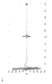
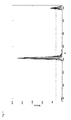
- FIG. 2 A received, sampled ultrasonic measurement signal is shown with the transmit pulse, the first echo and the subsequent multiple echo.
- the n-scan values are indicated on the x-axis, and the corresponding sampled received signal value x [n] on the y-axis in arbitrary units.
- the first almost 200 samples correspond to the directly injected into the receiver 3 transmit pulse.
- the transit time is preferably determined between two successive echoes.
- a first echo is approximately at the sample 1000, the subsequent multiple echo at the sample 2000.
- the sample has been chosen to be very high in this example. Typically, sampling is at typical sample rates of 1 MHz to 400 MHz.
- the received, sampled signal is then scaled to the required temporal accuracy .DELTA.t. This is done by inserting one zero or more zeroes each between the actual sample points. For example, if the temporal resolution is to be twice the actual sampling rate, then insert a "0" into the record between each sample. Typical values for temporal accuracy are 10ns, 1ns, 100ps.
- the temporal accuracy of the transit time determination .DELTA.t is an integer multiple of the sampling rate as a result of filling with zeros.
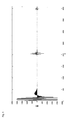
- the result of such filling with zero values of the received signal Fig. 2 is in Fig. 3 shown.
- the zero values between the samples make the areas appear filled under the enveloping curve.
- a zero was inserted between two samples. Therefore, the first echo is now approximately at sample 2000 and the second echo at sample 4000.
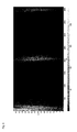
- the result W diskr (a, b) of such a wavelet transformation is in Fig. 4 shown.
- the gray values in the graph correspond to the values of the wavelet transforms W (a, b), the x-axis shows the associated translation parameter b, the y-axis the dilation parameter a.
- a dark value of the function W (a, b) of the "comparison" of base wavelet and received signal by means of the wavelet transformation shows that there is no relationship between the base wavelet and the received signal.
- a bright value corresponds to a relationship between the base wavelet and the received signal.
- the transmission pulse coupled directly into the receiver 3 can be seen, with values of approximately 2000 and 4000 the echoes.
- the values for b ⁇ 200 corresponding to the transmit pulse are not of interest for further processing in a preferred embodiment of the invention. Consequently, only the range in which the echoes are to be expected is considered to be between 400 ⁇ b ⁇ 4096 in the presently exemplary embodiment.
- the duration of the dying out of the transmitted pulse is determined by the measuring system and is known to the user. Thus, this area can be easily determined for the evaluation and then not taken into account.
- the optimal scaling a opt results from the position of the maximum in W max (a).
- the determination of the energy content for each scaling is possible.
- the wavelet transform is extracted with the determined optimal scaling a opt from W (a, b).
- W (a, b) W (a opt , b), ie in the embodiment W (33, b), is extracted for all b values.
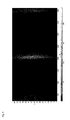
- the wavelet transform is in FIG. 7 shown.
- the result of the wavelet transformation W (a opt , b) is also used only for the echo range, since the runtime is to be determined as an example between two successive echoes.
- the echoes lie in the range 400 ⁇ b ⁇ 4096.
- the translation parameter b Echo1 for the first echo and b Echho2 for the second echo of the ultrasound measurement pulse are then determined by using established methods for the evaluation of ultrasound signals.
- other characteristic points are also suitable for the transit time measurement. These can be, for example, the echo start or the echo center. In the exemplary embodiment shown, the maximum is used as the characteristic point of the echoes.
- the method according to the invention is not limited to the reflection of a measurement pulse in or on a measurement object, but can also be used in the sound transmission of a measurement object.
- the reflection transmitter 1 and receiver 3 are arranged on the same side of the measurement object, in the sound transmission on opposite sides.
- a measuring pulse is coupled via a first side of the measurement object into the measurement object, passes through the measurement object and leaves it on another, second side.
- the time of transmission is again recorded or stored or started at this time, the receiver 3 and then uses the received signal on the second side for the wavelet transformation.
- the optimal dilation parameter a opt is determined once, and above this the associated parameter b and with it the transit time via equation 8 are determined.
- the arithmetic unit 5 is adapted such that the steps of the method according to the invention can be carried out.
Landscapes
- Physics & Mathematics (AREA)
- Engineering & Computer Science (AREA)
- General Physics & Mathematics (AREA)
- Chemical & Material Sciences (AREA)
- Biochemistry (AREA)
- Remote Sensing (AREA)
- Health & Medical Sciences (AREA)
- Life Sciences & Earth Sciences (AREA)
- Radar, Positioning & Navigation (AREA)
- Analytical Chemistry (AREA)
- Signal Processing (AREA)
- General Health & Medical Sciences (AREA)
- Immunology (AREA)
- Pathology (AREA)
- Acoustics & Sound (AREA)
- Computer Networks & Wireless Communication (AREA)
- Mathematical Physics (AREA)
- Spectroscopy & Molecular Physics (AREA)
- Investigating Or Analyzing Materials By The Use Of Ultrasonic Waves (AREA)
Applications Claiming Priority (1)
| Application Number | Priority Date | Filing Date | Title |
|---|---|---|---|
| DE102012202189A DE102012202189B3 (de) | 2012-02-14 | 2012-02-14 | Verfahren und Vorrichtung zur Wavelet basierten Laufzeitmessung von Ultraschallimpulsen |
Publications (3)
| Publication Number | Publication Date |
|---|---|
| EP2629089A2 true EP2629089A2 (fr) | 2013-08-21 |
| EP2629089A3 EP2629089A3 (fr) | 2014-12-10 |
| EP2629089B1 EP2629089B1 (fr) | 2019-04-03 |
Family
ID=47428499
Family Applications (1)
| Application Number | Title | Priority Date | Filing Date |
|---|---|---|---|
| EP12194790.7A Not-in-force EP2629089B1 (fr) | 2012-02-14 | 2012-11-29 | Procédé et dispositif de mesure de temps de propagation d'impulsions ultrasonores basée sur des ondelettes |
Country Status (2)
| Country | Link |
|---|---|
| EP (1) | EP2629089B1 (fr) |
| DE (1) | DE102012202189B3 (fr) |
Cited By (2)
| Publication number | Priority date | Publication date | Assignee | Title |
|---|---|---|---|---|
| CN111189528A (zh) * | 2020-01-09 | 2020-05-22 | 天津大学 | 一种基于飞秒激光频率梳的高精度水下声速测量方法 |
| CN116165278A (zh) * | 2023-01-19 | 2023-05-26 | 大连理工大学 | 基于多重小波分解和时间反转的结构冲击定位方法 |
Families Citing this family (1)
| Publication number | Priority date | Publication date | Assignee | Title |
|---|---|---|---|---|
| GB2582545B (en) | 2019-03-14 | 2021-04-14 | Darkvision Tech | Compressing ultrasound data in a downhole tool |
Citations (1)
| Publication number | Priority date | Publication date | Assignee | Title |
|---|---|---|---|---|
| DE102005015456A1 (de) | 2005-04-04 | 2006-10-05 | Viasys Healthcare Gmbh | Verfahren zur Bestimmung der zeitlichen Lage eines Wellenpakets sowie Flussmessgerät |
Family Cites Families (1)
| Publication number | Priority date | Publication date | Assignee | Title |
|---|---|---|---|---|
| JP5629481B2 (ja) * | 2010-03-16 | 2014-11-19 | 富士重工業株式会社 | 損傷診断システム |
-
2012
- 2012-02-14 DE DE102012202189A patent/DE102012202189B3/de not_active Expired - Fee Related
- 2012-11-29 EP EP12194790.7A patent/EP2629089B1/fr not_active Not-in-force
Patent Citations (1)
| Publication number | Priority date | Publication date | Assignee | Title |
|---|---|---|---|---|
| DE102005015456A1 (de) | 2005-04-04 | 2006-10-05 | Viasys Healthcare Gmbh | Verfahren zur Bestimmung der zeitlichen Lage eines Wellenpakets sowie Flussmessgerät |
Cited By (2)
| Publication number | Priority date | Publication date | Assignee | Title |
|---|---|---|---|---|
| CN111189528A (zh) * | 2020-01-09 | 2020-05-22 | 天津大学 | 一种基于飞秒激光频率梳的高精度水下声速测量方法 |
| CN116165278A (zh) * | 2023-01-19 | 2023-05-26 | 大连理工大学 | 基于多重小波分解和时间反转的结构冲击定位方法 |
Also Published As
| Publication number | Publication date |
|---|---|
| EP2629089B1 (fr) | 2019-04-03 |
| DE102012202189B3 (de) | 2013-02-07 |
| EP2629089A3 (fr) | 2014-12-10 |
Similar Documents
| Publication | Publication Date | Title |
|---|---|---|
| DE69218331T2 (de) | Rauschpegelverringerung in Radargeräten für Streuziele | |
| DE102013211846A1 (de) | Verfahren zum Betrieb eines Umfelderfassungssystems eines Fahrzeugs | |
| DE3120284C2 (fr) | ||
| EP3170022B1 (fr) | Localisation d'objet, robuste au bruit, avec des ultrasons | |
| EP1875380A2 (fr) | Procede pour determiner la position temporelle d'un paquet de d'ondes et appareil de mesure de flux | |
| DE102013212664A1 (de) | Radarsensor und Verfahren zum Betrieb eines Radarsensors | |
| DE202019107029U1 (de) | Akustische Distanzmessschaltung | |
| DE102012200743A1 (de) | Verfahren zur Bestimmung der Position und/oder der Bewegung mindestens eines Objektes in der Umgebung eines Fahrzeuges und/oder zur Informationsübertragung mittels mindestens eines gesendeten akustischen Signals und Umfelderfassungsvorrichtung zum Durchführen des Verfahrens | |
| DE69524553T2 (de) | Hochauflösende Dickenmessung mit Ultraschall | |
| EP2629089B1 (fr) | Procédé et dispositif de mesure de temps de propagation d'impulsions ultrasonores basée sur des ondelettes | |
| DE102018106251A1 (de) | Verfahren komprimierten Übertragung von Daten eines Ultraschallsensorsystems durch Nichtübertragung erkannter unwichtiger Signalobjekte auf Basis von mindestens zwei Parametersignalen | |
| DE102018010258A1 (de) | Klassifikation von Signalobjekten innerhalb von Ultraschallempfangssignalen und komprimierten Übertragung von Symbolen als Repräsentanten dieser Signalobjekte an eine Rechnereinheit zur Objekterkennung | |
| DE102010020023A1 (de) | Verfahren und Vorrichtung zur Rauschoptimierung eines Echosignals zur Fahrzeugumfelderfassung sowie zugehörige Vorrichtung zur Fahrzeugumfelderfassung | |
| DE102018010261A1 (de) | Klassifikation von Signalobjekten innerhalb von Ultraschallempfangssignalen und komprimierten Übertragung von Symbolen als Repräsentanten dieser Signalobjekte an eine Rechnereinheit zur Objekterkennung | |
| DE3435989C2 (de) | Verfahren zur Wanddickenmessung von Körpern mittels Ultraschallimpulsen und Vorrichtung zur Durchführung des Verfahrens | |
| EP2428816A1 (fr) | Procédé et dispositif de détermination d'un décalage de fréquence doppler résultant de l'effet doppler | |
| DE102019106432A1 (de) | Verfahren komprimierten Übertragung von Daten eines Ultraschallsensorsystems durch Nichtübertragung erkannter unwichtiger Signalobjekte | |
| EP3132282A1 (fr) | Dispositif et procédé de détection sonore d'un environnement | |
| DE102018010260A1 (de) | Klassifikation von Signalobjekten innerhalb von Ultraschallempfangssignalen und komprimierten Übertragung von Symbolen als Repräsentanten dieser Signalobjekte an eine Rechnereinheit zur Objekterkennung | |
| DE102018010255A1 (de) | Klassifikation von Signalobjekten innerhalb von Ultraschallempfangssignalen und komprimierten Übertragung von Symbolen als Repräsentanten dieser Signalobjekte an eine Rechnereinheit zur Objekterkennung | |
| EP2877877B1 (fr) | Procédé d'exploitation d'un système d'acquisition de l'environnement d'un véhicule et système d'acquisition d'environnement | |
| WO2025067731A1 (fr) | Procédé de classification d'un objet à détecter à l'aide d'au moins un capteur ultrasonore prenant en compte des informations de phase du signal acquis | |
| EP2789996B1 (fr) | Détermination de courbe d'échos avec résolution différente selon la zone | |
| DE102010039978A1 (de) | Verfahren und Vorrichtung zur Messung einer Laufzeit eines Pulses | |
| DE102010063937A1 (de) | Verfahren und Vorrichtung zur Messung von Laufzeiten von Ultraschallimpulsen |
Legal Events
| Date | Code | Title | Description |
|---|---|---|---|
| PUAI | Public reference made under article 153(3) epc to a published international application that has entered the european phase |
Free format text: ORIGINAL CODE: 0009012 |
|
| 17P | Request for examination filed |
Effective date: 20121129 |
|
| AK | Designated contracting states |
Kind code of ref document: A2 Designated state(s): AL AT BE BG CH CY CZ DE DK EE ES FI FR GB GR HR HU IE IS IT LI LT LU LV MC MK MT NL NO PL PT RO RS SE SI SK SM TR |
|
| AX | Request for extension of the european patent |
Extension state: BA ME |
|
| PUAL | Search report despatched |
Free format text: ORIGINAL CODE: 0009013 |
|
| AK | Designated contracting states |
Kind code of ref document: A3 Designated state(s): AL AT BE BG CH CY CZ DE DK EE ES FI FR GB GR HR HU IE IS IT LI LT LU LV MC MK MT NL NO PL PT RO RS SE SI SK SM TR |
|
| AX | Request for extension of the european patent |
Extension state: BA ME |
|
| RIC1 | Information provided on ipc code assigned before grant |
Ipc: G01N 29/46 20060101ALI20141103BHEP Ipc: G01N 29/44 20060101ALI20141103BHEP Ipc: G01N 29/07 20060101AFI20141103BHEP |
|
| STAA | Information on the status of an ep patent application or granted ep patent |
Free format text: STATUS: EXAMINATION IS IN PROGRESS |
|
| 17Q | First examination report despatched |
Effective date: 20170530 |
|
| GRAP | Despatch of communication of intention to grant a patent |
Free format text: ORIGINAL CODE: EPIDOSNIGR1 |
|
| STAA | Information on the status of an ep patent application or granted ep patent |
Free format text: STATUS: GRANT OF PATENT IS INTENDED |
|
| INTG | Intention to grant announced |
Effective date: 20181029 |
|
| GRAS | Grant fee paid |
Free format text: ORIGINAL CODE: EPIDOSNIGR3 |
|
| GRAA | (expected) grant |
Free format text: ORIGINAL CODE: 0009210 |
|
| STAA | Information on the status of an ep patent application or granted ep patent |
Free format text: STATUS: THE PATENT HAS BEEN GRANTED |
|
| AK | Designated contracting states |
Kind code of ref document: B1 Designated state(s): AL AT BE BG CH CY CZ DE DK EE ES FI FR GB GR HR HU IE IS IT LI LT LU LV MC MK MT NL NO PL PT RO RS SE SI SK SM TR |
|
| REG | Reference to a national code |
Ref country code: GB Ref legal event code: FG4D Free format text: NOT ENGLISH |
|
| REG | Reference to a national code |
Ref country code: CH Ref legal event code: EP Ref country code: AT Ref legal event code: REF Ref document number: 1116363 Country of ref document: AT Kind code of ref document: T Effective date: 20190415 |
|
| REG | Reference to a national code |
Ref country code: DE Ref legal event code: R096 Ref document number: 502012014534 Country of ref document: DE |
|
| REG | Reference to a national code |
Ref country code: IE Ref legal event code: FG4D Free format text: LANGUAGE OF EP DOCUMENT: GERMAN |
|
| REG | Reference to a national code |
Ref country code: NL Ref legal event code: MP Effective date: 20190403 |
|
| REG | Reference to a national code |
Ref country code: LT Ref legal event code: MG4D |
|
| PG25 | Lapsed in a contracting state [announced via postgrant information from national office to epo] |
Ref country code: NL Free format text: LAPSE BECAUSE OF FAILURE TO SUBMIT A TRANSLATION OF THE DESCRIPTION OR TO PAY THE FEE WITHIN THE PRESCRIBED TIME-LIMIT Effective date: 20190403 |
|
| PG25 | Lapsed in a contracting state [announced via postgrant information from national office to epo] |
Ref country code: PT Free format text: LAPSE BECAUSE OF FAILURE TO SUBMIT A TRANSLATION OF THE DESCRIPTION OR TO PAY THE FEE WITHIN THE PRESCRIBED TIME-LIMIT Effective date: 20190803 Ref country code: ES Free format text: LAPSE BECAUSE OF FAILURE TO SUBMIT A TRANSLATION OF THE DESCRIPTION OR TO PAY THE FEE WITHIN THE PRESCRIBED TIME-LIMIT Effective date: 20190403 Ref country code: SE Free format text: LAPSE BECAUSE OF FAILURE TO SUBMIT A TRANSLATION OF THE DESCRIPTION OR TO PAY THE FEE WITHIN THE PRESCRIBED TIME-LIMIT Effective date: 20190403 Ref country code: AL Free format text: LAPSE BECAUSE OF FAILURE TO SUBMIT A TRANSLATION OF THE DESCRIPTION OR TO PAY THE FEE WITHIN THE PRESCRIBED TIME-LIMIT Effective date: 20190403 Ref country code: NO Free format text: LAPSE BECAUSE OF FAILURE TO SUBMIT A TRANSLATION OF THE DESCRIPTION OR TO PAY THE FEE WITHIN THE PRESCRIBED TIME-LIMIT Effective date: 20190703 Ref country code: FI Free format text: LAPSE BECAUSE OF FAILURE TO SUBMIT A TRANSLATION OF THE DESCRIPTION OR TO PAY THE FEE WITHIN THE PRESCRIBED TIME-LIMIT Effective date: 20190403 Ref country code: HR Free format text: LAPSE BECAUSE OF FAILURE TO SUBMIT A TRANSLATION OF THE DESCRIPTION OR TO PAY THE FEE WITHIN THE PRESCRIBED TIME-LIMIT Effective date: 20190403 Ref country code: LT Free format text: LAPSE BECAUSE OF FAILURE TO SUBMIT A TRANSLATION OF THE DESCRIPTION OR TO PAY THE FEE WITHIN THE PRESCRIBED TIME-LIMIT Effective date: 20190403 |
|
| PG25 | Lapsed in a contracting state [announced via postgrant information from national office to epo] |
Ref country code: RS Free format text: LAPSE BECAUSE OF FAILURE TO SUBMIT A TRANSLATION OF THE DESCRIPTION OR TO PAY THE FEE WITHIN THE PRESCRIBED TIME-LIMIT Effective date: 20190403 Ref country code: PL Free format text: LAPSE BECAUSE OF FAILURE TO SUBMIT A TRANSLATION OF THE DESCRIPTION OR TO PAY THE FEE WITHIN THE PRESCRIBED TIME-LIMIT Effective date: 20190403 Ref country code: BG Free format text: LAPSE BECAUSE OF FAILURE TO SUBMIT A TRANSLATION OF THE DESCRIPTION OR TO PAY THE FEE WITHIN THE PRESCRIBED TIME-LIMIT Effective date: 20190703 Ref country code: LV Free format text: LAPSE BECAUSE OF FAILURE TO SUBMIT A TRANSLATION OF THE DESCRIPTION OR TO PAY THE FEE WITHIN THE PRESCRIBED TIME-LIMIT Effective date: 20190403 Ref country code: GR Free format text: LAPSE BECAUSE OF FAILURE TO SUBMIT A TRANSLATION OF THE DESCRIPTION OR TO PAY THE FEE WITHIN THE PRESCRIBED TIME-LIMIT Effective date: 20190704 |
|
| PG25 | Lapsed in a contracting state [announced via postgrant information from national office to epo] |
Ref country code: IS Free format text: LAPSE BECAUSE OF FAILURE TO SUBMIT A TRANSLATION OF THE DESCRIPTION OR TO PAY THE FEE WITHIN THE PRESCRIBED TIME-LIMIT Effective date: 20190803 |
|
| REG | Reference to a national code |
Ref country code: DE Ref legal event code: R097 Ref document number: 502012014534 Country of ref document: DE |
|
| PG25 | Lapsed in a contracting state [announced via postgrant information from national office to epo] |
Ref country code: EE Free format text: LAPSE BECAUSE OF FAILURE TO SUBMIT A TRANSLATION OF THE DESCRIPTION OR TO PAY THE FEE WITHIN THE PRESCRIBED TIME-LIMIT Effective date: 20190403 Ref country code: DK Free format text: LAPSE BECAUSE OF FAILURE TO SUBMIT A TRANSLATION OF THE DESCRIPTION OR TO PAY THE FEE WITHIN THE PRESCRIBED TIME-LIMIT Effective date: 20190403 Ref country code: SK Free format text: LAPSE BECAUSE OF FAILURE TO SUBMIT A TRANSLATION OF THE DESCRIPTION OR TO PAY THE FEE WITHIN THE PRESCRIBED TIME-LIMIT Effective date: 20190403 Ref country code: RO Free format text: LAPSE BECAUSE OF FAILURE TO SUBMIT A TRANSLATION OF THE DESCRIPTION OR TO PAY THE FEE WITHIN THE PRESCRIBED TIME-LIMIT Effective date: 20190403 |
|
| PLBE | No opposition filed within time limit |
Free format text: ORIGINAL CODE: 0009261 |
|
| STAA | Information on the status of an ep patent application or granted ep patent |
Free format text: STATUS: NO OPPOSITION FILED WITHIN TIME LIMIT |
|
| PG25 | Lapsed in a contracting state [announced via postgrant information from national office to epo] |
Ref country code: IT Free format text: LAPSE BECAUSE OF FAILURE TO SUBMIT A TRANSLATION OF THE DESCRIPTION OR TO PAY THE FEE WITHIN THE PRESCRIBED TIME-LIMIT Effective date: 20190403 Ref country code: SM Free format text: LAPSE BECAUSE OF FAILURE TO SUBMIT A TRANSLATION OF THE DESCRIPTION OR TO PAY THE FEE WITHIN THE PRESCRIBED TIME-LIMIT Effective date: 20190403 |
|
| 26N | No opposition filed |
Effective date: 20200106 |
|
| PG25 | Lapsed in a contracting state [announced via postgrant information from national office to epo] |
Ref country code: TR Free format text: LAPSE BECAUSE OF FAILURE TO SUBMIT A TRANSLATION OF THE DESCRIPTION OR TO PAY THE FEE WITHIN THE PRESCRIBED TIME-LIMIT Effective date: 20190403 |
|
| PG25 | Lapsed in a contracting state [announced via postgrant information from national office to epo] |
Ref country code: SI Free format text: LAPSE BECAUSE OF FAILURE TO SUBMIT A TRANSLATION OF THE DESCRIPTION OR TO PAY THE FEE WITHIN THE PRESCRIBED TIME-LIMIT Effective date: 20190403 |
|
| REG | Reference to a national code |
Ref country code: CH Ref legal event code: PL |
|
| PG25 | Lapsed in a contracting state [announced via postgrant information from national office to epo] |
Ref country code: LU Free format text: LAPSE BECAUSE OF NON-PAYMENT OF DUE FEES Effective date: 20191129 Ref country code: MC Free format text: LAPSE BECAUSE OF FAILURE TO SUBMIT A TRANSLATION OF THE DESCRIPTION OR TO PAY THE FEE WITHIN THE PRESCRIBED TIME-LIMIT Effective date: 20190403 Ref country code: CH Free format text: LAPSE BECAUSE OF NON-PAYMENT OF DUE FEES Effective date: 20191130 Ref country code: LI Free format text: LAPSE BECAUSE OF NON-PAYMENT OF DUE FEES Effective date: 20191130 |
|
| REG | Reference to a national code |
Ref country code: BE Ref legal event code: MM Effective date: 20191130 |
|
| PG25 | Lapsed in a contracting state [announced via postgrant information from national office to epo] |
Ref country code: IE Free format text: LAPSE BECAUSE OF NON-PAYMENT OF DUE FEES Effective date: 20191129 Ref country code: FR Free format text: LAPSE BECAUSE OF NON-PAYMENT OF DUE FEES Effective date: 20191130 |
|
| PG25 | Lapsed in a contracting state [announced via postgrant information from national office to epo] |
Ref country code: BE Free format text: LAPSE BECAUSE OF NON-PAYMENT OF DUE FEES Effective date: 20191130 |
|
| REG | Reference to a national code |
Ref country code: AT Ref legal event code: MM01 Ref document number: 1116363 Country of ref document: AT Kind code of ref document: T Effective date: 20191129 |
|
| PG25 | Lapsed in a contracting state [announced via postgrant information from national office to epo] |
Ref country code: AT Free format text: LAPSE BECAUSE OF NON-PAYMENT OF DUE FEES Effective date: 20191129 |
|
| PG25 | Lapsed in a contracting state [announced via postgrant information from national office to epo] |
Ref country code: CY Free format text: LAPSE BECAUSE OF FAILURE TO SUBMIT A TRANSLATION OF THE DESCRIPTION OR TO PAY THE FEE WITHIN THE PRESCRIBED TIME-LIMIT Effective date: 20190403 |
|
| PG25 | Lapsed in a contracting state [announced via postgrant information from national office to epo] |
Ref country code: HU Free format text: LAPSE BECAUSE OF FAILURE TO SUBMIT A TRANSLATION OF THE DESCRIPTION OR TO PAY THE FEE WITHIN THE PRESCRIBED TIME-LIMIT; INVALID AB INITIO Effective date: 20121129 Ref country code: MT Free format text: LAPSE BECAUSE OF FAILURE TO SUBMIT A TRANSLATION OF THE DESCRIPTION OR TO PAY THE FEE WITHIN THE PRESCRIBED TIME-LIMIT Effective date: 20190403 |
|
| PG25 | Lapsed in a contracting state [announced via postgrant information from national office to epo] |
Ref country code: MK Free format text: LAPSE BECAUSE OF FAILURE TO SUBMIT A TRANSLATION OF THE DESCRIPTION OR TO PAY THE FEE WITHIN THE PRESCRIBED TIME-LIMIT Effective date: 20190403 |
|
| P01 | Opt-out of the competence of the unified patent court (upc) registered |
Effective date: 20230509 |
|
| P02 | Opt-out of the competence of the unified patent court (upc) changed |
Effective date: 20230525 |
|
| PGFP | Annual fee paid to national office [announced via postgrant information from national office to epo] |
Ref country code: GB Payment date: 20231123 Year of fee payment: 12 |
|
| PGFP | Annual fee paid to national office [announced via postgrant information from national office to epo] |
Ref country code: DE Payment date: 20231229 Year of fee payment: 12 Ref country code: CZ Payment date: 20231116 Year of fee payment: 12 |
|
| REG | Reference to a national code |
Ref country code: DE Ref legal event code: R119 Ref document number: 502012014534 Country of ref document: DE |
|
| GBPC | Gb: european patent ceased through non-payment of renewal fee |
Effective date: 20241129 |
|
| PG25 | Lapsed in a contracting state [announced via postgrant information from national office to epo] |
Ref country code: CZ Free format text: LAPSE BECAUSE OF NON-PAYMENT OF DUE FEES Effective date: 20241129 |
|
| PG25 | Lapsed in a contracting state [announced via postgrant information from national office to epo] |
Ref country code: DE Free format text: LAPSE BECAUSE OF NON-PAYMENT OF DUE FEES Effective date: 20250603 |
|
| PG25 | Lapsed in a contracting state [announced via postgrant information from national office to epo] |
Ref country code: GB Free format text: LAPSE BECAUSE OF NON-PAYMENT OF DUE FEES Effective date: 20241129 |