EP2629122A2 - Direktionale Widerstandsmessungen für azimuthale Näherungserkennung von Schichtgrenzen - Google Patents
Direktionale Widerstandsmessungen für azimuthale Näherungserkennung von Schichtgrenzen Download PDFInfo
- Publication number
- EP2629122A2 EP2629122A2 EP13167569.6A EP13167569A EP2629122A2 EP 2629122 A2 EP2629122 A2 EP 2629122A2 EP 13167569 A EP13167569 A EP 13167569A EP 2629122 A2 EP2629122 A2 EP 2629122A2
- Authority
- EP
- European Patent Office
- Prior art keywords
- tool
- receiver
- skewed
- coils
- transmitter
- Prior art date
- Legal status (The legal status is an assumption and is not a legal conclusion. Google has not performed a legal analysis and makes no representation as to the accuracy of the status listed.)
- Granted
Links
- 238000005259 measurement Methods 0.000 title claims abstract description 60
- 238000001514 detection method Methods 0.000 title 1
- 230000015572 biosynthetic process Effects 0.000 claims abstract description 81
- 238000000034 method Methods 0.000 claims abstract description 47
- 230000010363 phase shift Effects 0.000 claims abstract description 18
- 230000035945 sensitivity Effects 0.000 claims abstract description 14
- 230000001902 propagating effect Effects 0.000 claims abstract description 5
- 238000005553 drilling Methods 0.000 claims description 52
- 239000013598 vector Substances 0.000 claims description 12
- 230000008569 process Effects 0.000 claims description 6
- 238000012937 correction Methods 0.000 claims description 5
- 238000011835 investigation Methods 0.000 claims description 5
- 238000012545 processing Methods 0.000 claims description 3
- 238000005755 formation reaction Methods 0.000 description 69
- 230000004044 response Effects 0.000 description 19
- 230000006870 function Effects 0.000 description 11
- 238000007796 conventional method Methods 0.000 description 6
- 230000011664 signaling Effects 0.000 description 6
- 239000003208 petroleum Substances 0.000 description 5
- XQCFHQBGMWUEMY-ZPUQHVIOSA-N Nitrovin Chemical compound C=1C=C([N+]([O-])=O)OC=1\C=C\C(=NNC(=N)N)\C=C\C1=CC=C([N+]([O-])=O)O1 XQCFHQBGMWUEMY-ZPUQHVIOSA-N 0.000 description 4
- 230000008859 change Effects 0.000 description 4
- 230000008878 coupling Effects 0.000 description 4
- 238000010168 coupling process Methods 0.000 description 4
- 238000005859 coupling reaction Methods 0.000 description 4
- 230000006698 induction Effects 0.000 description 4
- 239000011435 rock Substances 0.000 description 4
- 238000003786 synthesis reaction Methods 0.000 description 4
- 238000013459 approach Methods 0.000 description 3
- 230000000694 effects Effects 0.000 description 3
- 239000003381 stabilizer Substances 0.000 description 3
- 230000008901 benefit Effects 0.000 description 2
- 238000010276 construction Methods 0.000 description 2
- 238000013500 data storage Methods 0.000 description 2
- 238000013461 design Methods 0.000 description 2
- 238000010586 diagram Methods 0.000 description 2
- 230000033001 locomotion Effects 0.000 description 2
- 238000004519 manufacturing process Methods 0.000 description 2
- 239000000463 material Substances 0.000 description 2
- 239000000523 sample Substances 0.000 description 2
- 239000004576 sand Substances 0.000 description 2
- 230000002194 synthesizing effect Effects 0.000 description 2
- 230000032258 transport Effects 0.000 description 2
- 239000004593 Epoxy Substances 0.000 description 1
- 229910000831 Steel Inorganic materials 0.000 description 1
- 230000004913 activation Effects 0.000 description 1
- 238000000429 assembly Methods 0.000 description 1
- 230000000712 assembly Effects 0.000 description 1
- 230000005540 biological transmission Effects 0.000 description 1
- 239000000919 ceramic Substances 0.000 description 1
- 238000004891 communication Methods 0.000 description 1
- 239000011231 conductive filler Substances 0.000 description 1
- 239000004020 conductor Substances 0.000 description 1
- 230000002596 correlated effect Effects 0.000 description 1
- 238000005520 cutting process Methods 0.000 description 1
- 230000003247 decreasing effect Effects 0.000 description 1
- 229920001971 elastomer Polymers 0.000 description 1
- 230000005284 excitation Effects 0.000 description 1
- 238000001914 filtration Methods 0.000 description 1
- 239000012530 fluid Substances 0.000 description 1
- 230000004907 flux Effects 0.000 description 1
- 229930195733 hydrocarbon Natural products 0.000 description 1
- 150000002430 hydrocarbons Chemical class 0.000 description 1
- 238000009434 installation Methods 0.000 description 1
- 230000009545 invasion Effects 0.000 description 1
- 238000012986 modification Methods 0.000 description 1
- 230000004048 modification Effects 0.000 description 1
- 239000003129 oil well Substances 0.000 description 1
- 230000000149 penetrating effect Effects 0.000 description 1
- 230000000704 physical effect Effects 0.000 description 1
- 238000011084 recovery Methods 0.000 description 1
- 239000005060 rubber Substances 0.000 description 1
- 229920006395 saturated elastomer Polymers 0.000 description 1
- 230000035939 shock Effects 0.000 description 1
- 239000010959 steel Substances 0.000 description 1
- 238000001308 synthesis method Methods 0.000 description 1
Images




Classifications
-
- G—PHYSICS
- G01—MEASURING; TESTING
- G01V—GEOPHYSICS; GRAVITATIONAL MEASUREMENTS; DETECTING MASSES OR OBJECTS; TAGS
- G01V3/00—Electric or magnetic prospecting or detecting; Measuring magnetic field characteristics of the earth, e.g. declination, deviation
- G01V3/18—Electric or magnetic prospecting or detecting; Measuring magnetic field characteristics of the earth, e.g. declination, deviation specially adapted for well-logging
- G01V3/26—Electric or magnetic prospecting or detecting; Measuring magnetic field characteristics of the earth, e.g. declination, deviation specially adapted for well-logging operating with magnetic or electric fields produced or modified either by the surrounding earth formation or by the detecting device
- G01V3/28—Electric or magnetic prospecting or detecting; Measuring magnetic field characteristics of the earth, e.g. declination, deviation specially adapted for well-logging operating with magnetic or electric fields produced or modified either by the surrounding earth formation or by the detecting device using induction coils
-
- E—FIXED CONSTRUCTIONS
- E21—EARTH OR ROCK DRILLING; MINING
- E21B—EARTH OR ROCK DRILLING; OBTAINING OIL, GAS, WATER, SOLUBLE OR MELTABLE MATERIALS OR A SLURRY OF MINERALS FROM WELLS
- E21B47/00—Survey of boreholes or wells
- E21B47/02—Determining slope or direction
- E21B47/022—Determining slope or direction of the borehole, e.g. using geomagnetism
- E21B47/0228—Determining slope or direction of the borehole, e.g. using geomagnetism using electromagnetic energy or detectors therefor
-
- E—FIXED CONSTRUCTIONS
- E21—EARTH OR ROCK DRILLING; MINING
- E21B—EARTH OR ROCK DRILLING; OBTAINING OIL, GAS, WATER, SOLUBLE OR MELTABLE MATERIALS OR A SLURRY OF MINERALS FROM WELLS
- E21B47/00—Survey of boreholes or wells
- E21B47/02—Determining slope or direction
- E21B47/026—Determining slope or direction of penetrated ground layers
-
- G—PHYSICS
- G01—MEASURING; TESTING
- G01V—GEOPHYSICS; GRAVITATIONAL MEASUREMENTS; DETECTING MASSES OR OBJECTS; TAGS
- G01V3/00—Electric or magnetic prospecting or detecting; Measuring magnetic field characteristics of the earth, e.g. declination, deviation
- G01V3/18—Electric or magnetic prospecting or detecting; Measuring magnetic field characteristics of the earth, e.g. declination, deviation specially adapted for well-logging
- G01V3/30—Electric or magnetic prospecting or detecting; Measuring magnetic field characteristics of the earth, e.g. declination, deviation specially adapted for well-logging operating with electromagnetic waves
Definitions
- the present invention relates generally to a bottomhole drilling assembly that includes a logging while drilling ("LWD") sub-system for determining characteristics of the borehole and formation during the drilling of a well. More particularly, the present invention relates to a resistivity logging tool for measuring formation resistivity parameters during drilling. Still more particularly, the present invention comprises an azimuthally tunable resistivity tool to facilitate navigation relative to a bed boundary during drilling.
- LWD logging while drilling
- a probe or "sonde” having various sensors is lowered into the borehole after some or all of the well has been drilled.
- the sonde is typically constructed as a hermetically sealed steel cylinder for housing the sensors, and is typically suspended from the end of a long cable or "wireline".
- the wireline mechanically suspends the sonde and also provides electrical conductors between the sensors (and associated instrumentation within the sonde) and electrical equipment located at the surface of the well.
- the cable transports power and control signals to the sonde, and transports information signals from the sonde to the surface.
- various parameters of the earth's formations adjacent the borehole are measured and correlated with the position of the sonde in the borehole as the sonde is pulled uphole.
- the sensors used in a wireline sonde may include a source device for transmitting energy into the formation, and one or more receivers for detecting the energy reflected from the formation.
- Various sensors have been used to determine particular characteristics of the formation, including nuclear sensors, acoustic sensors, and electrical sensors.
- the rock comprising the formation must have certain well known physical characteristics.
- one characteristic is that the rock in the formation have space to store petroleum. If the rock in a formation has openings, voids, and spaces in which oil and gas may be stored, it is characterized as "porous".
- Various wireline sensors may be used to measure formation porosity. Examples include the acoustic sensors described in US Patent Nos. 3,237,153 , 3,312,934 , 3,593,255 , 4,649,525 , 4,718,046 , 4,869,349 , and 5,069,308 .
- wireline logging is useful in assimilating information relating to formations downhole, it nonetheless has certain disadvantages.
- the drillstring and bottomhole assembly must first be removed or "tripped" from the borehole, resulting in considerable expense and a loss of drilling time for the driller (who typically is paying daily fees for the rental of drilling equipment).
- wireline tools are unable to collect data during the actual drilling operation, drillers must at times make decisions (such as the direction to drill, etc.) based on limited and possibly insufficient information, or else incur the costs of tripping the drillstring to run a wireline logging tool.
- MWD Measurement-while drilling
- LWD logging while drilling
- LWD measurements are used to provide information regarding the particular formation in which the borehole is traversing.
- LWD system could be used as part of a "Smart" system to automatically maintain the drill bit in the pay zone. See, e.g. commonly assigned U.S. Patent No. 5,332,048 , the teachings of which are incorporated by reference herein.
- the assignee has also developed a system which permits the measurement of LWD data at the drill bit to provide an earlier indication of bed boundaries and formation characteristics. See U.S. Patent No. 5, 160,925 .
- the use of an LWD system with these other systems makes it possible to conduct at least certain portions of the drilling process automatically.
- a well is drilled vertically for at least a portion of its depth.
- the layers or strata that make up the earth's crust are generally substantially horizontal. Therefore, during vertical drilling, the well is substantially perpendicular to the geological formations through which it passes.
- One of the properties of the formation that is commonly logged is its resistivity.
- LWD tools that are designed to measure the resistivity of the surrounding formation need not be azimuthally focused, as the formation in question surrounds the wellbore and is essentially the same in all directions. Thus the rotation of the LWD tool with the bit has no significant effect on the measured resistivity. For this reason, typical LWD resistivity tools that are adapted for use in vertical wells are azimuthally symmetric and have no azimuthal sensitivity.
- a near-bit resistivity tool were capable of sensing resistivity values azimuthally, the sensed values could be analyzed to discern the direction of the bed boundary. If the tool were sufficiently sensitive, the approaching bed boundary would be detected in sufficient time to allow the driller to make corrections in accordance with known techniques to avoid exiting the desired formation.
- an LWD tool that allows azimuthally sensitive resistivity measurements, a tool that is easy to manufacture and assemble and that is sufficiently durable and reliable in the drilling environment.
- the tool comprises a set of three skewed receiver antennas and a transmitter antenna.
- the three skewed receiver antennas are oriented in equally spaced azimuthal directions to give them preferential sensitivity in those directions.
- the transmitter antenna transmits a radio-frequency signal that propagates through the formation surrounding a borehole.
- the signals from the three receiver antennas can be measured and combined to synthesize the signal that would be received by a virtual antenna oriented in any desired direction.
- virtual receivers oriented perpendicular to the tool axis and with variable azimuthal orientations can be synthesized. The orientation of such a virtual receiver that has a maximized receive signal amplitude can be used to identify the direction of a nearby bed boundary, and the maximized amplitude can be used to estimate the distance to the boundary.
- the tool comprises a set of three skewed transmitter antennas and a receiver antenna.
- the three skewed transmitter antennas are oriented in equally spaced azimuthal directions to give them preferential gain in those directions.
- the signals received by the receiver antenna in response to a signal from each of the transmitter antennas can be measured and combined to synthesize a signal received by the receiver antenna in response to a signal from a virtual transmitter antenna oriented in any desired direction.
- virtual transmitters oriented perpendicular to the tool axis with variable azimuthal orientations can be synthesized.
- the orientation of such a virtual antenna that creates a maximized response signal can be used to identify the direction of a nearby bed boundary, and the maximized amplitude can be used to estimate the distance to the boundary.
- the tool comprises a set of skewed transmitter antennas and a set of skewed receiver antennas.
- the skewed transmitter and receiver antennas work cooperatively to establish virtual transmitter/receiver pairs oriented in any desired azimuthal directions.
- This invention further contemplates a method for making azimuthally sensitive resistivity measurements and a method for detecting the location of a bed boundary relative to a borehole.
- the terms “above” and “below” are used to denote the relative position of certain components with respect to the direction of flow of the incoming drilling mud.
- drilling mud flows first through the first component before flowing through the second component.
- these and other terms are used to identify the relative position of components in the bottomhole assembly (or BHA), with respect to the distance to the surface of the well, measured along the wellbore path.
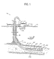
- a drilling installation is shown.
- a drilling rig 10 at the surface 12 of the well supports a drill string 14.
- the drill string 14 penetrates through a work platform 16 and into a borehole 18 that is drilled through earth formations 20 and 21.
- the drill string 14 may comprise coil tubing 24 from a spool 22 at its upper end, and a bottom hole assembly 26 (commonly referred to as a "BHA") coupled to the lower end of the coil tubing 24.
- BHA bottom hole assembly
- the BHA 26 may include a drill bit 32, a downhole motor 40, one or more drill collars 28, an azimuthally tunable resistivity tool 50 mounted on collar section 55 as described in detail below, LWD sensors positioned in a collar section 55, directional MWD sensors located in a non-magnetic section 60, and one or more stabilizer(s) (not shown) for penetrating through earth formations to create the borehole 18.
- the drill collars 28, which also may be non-magnetic so as not to interfere with the MWD measurements, are used in accordance with conventional techniques to add weight to the drill bit 32 and to stiffen the BHA 26, thereby enabling the BHA 26 to transmit weight to the drill bit 32 without buckling.
- the weight applied through the drill collars 28 to the bit 32 permits the drill bit to penetrate underground formations.
- Tubing injector 13 typically consists of an opposed pair of endless chains configured to grip the tubing. The chains may be driven in either direction to inject or withdraw the tubing from the borehole.
- drilling fluid or mud is pumped from a mud pit 34 at the surface through the hose 37, into the tubing 24, and to the drill bit 32.
- the drilling mud rises back to the surface through the annular area between the tubing 24 and the borehole 18, where it is collected and returned to the mud pit 34 for filtering.
- the drilling mud is used to lubricate and cool the drill bit 32 and to remove cuttings from the borehole 18.
- the drilling mud may also perform a number of other functions, which could include providing operating power to the downhole motor or other components downhole.
- the downhole motor or turbine 40 may be used downhole to rotate the drill bit 32.
- BHA 26 is defined as all of the downhole components from the top of the drill collars 28, down to the drill bit 32, including downhole motor 40.
- the BHA 26 preferably includes a measurement while drilling system, referred to herein as an "MWD system".
- an MWD system 60 typically includes directional MWD sensors and drilling parameter sensors such as weight-on-bit (WOB), torque-on-bit (TOB), shock, vibration, etc.
- directional sensors are provided in the BHA 26 to indicate the inclination angle, the horizontal angle, and the rotational angle (a.k.a. "tool face angle") of the BHA 26.
- the inclination angle is the deviation from vertically downward
- the horizontal angle is the angle in a horizontal plane from true North
- the tool face angle is the orientation (rotational about the tool axis) angle from the high side of the wellbore.
- wellbore directional measurements can be made as follows: a three axis accelerometer measures the earth's gravitational field vector relative to the tool axis and a point on the circumference of the tool called the "tool face scribe line". (The tool face scribe line is typically drawn on the tool surface as a line parallel to the tool axis.) From this measurement, the inclination and tool face angle of the BHA can be determined. Additionally, a three axis magnetometer measures the earth's magnetic field vector in a similar manner. From the combined magnetometer and accelerometer data, the horizontal angle of the BHA may be determined.
- the LWD tool 55 preferably is located close to the drill bit 32 to facilitate the ability to examine the formation as close to the bit as possible. As one skilled in the art will understand, the LWD tool 55 could also be located further up the BHA 26 from the drill bit 32 without departing from the principles of the present invention. Moreover, the LWD tool 55 may in actuality comprise multiple collar sections for housing various LWD sensors.
- the LWD formation sensors 55 preferably include the present azimuthally tunable resistivity sensor, as well as gamma, sonic, density and neutron sensors in accordance with normal industry practice. See generally " State of the Art in MWD", International MWD Society (January 19, 1993 ).
- a battery pack or other power source may be included in the LWD tool 55, or alternatively may be positioned in any convenient location to provide power to the various electrical assemblies in the BHA.
- downhole data signaling unit 35 is preferably provided as part of BHA 26 and is used to transmit sensed values to a surface receiver via a mud pulse acoustic signal.
- the drilling mud serves as a communication medium between the controller and components at the surface of the well.
- pressure pulses may be generated, in the form of acoustic signals, in the column of drilling mud.
- encoded binary pressure pulse signals can be generated to carry information indicative of downhole parameters to the surface for immediate analysis.
- the downhole system may also include the capability of receiving mud pulse signals from the surface to control the operation or activation of certain MWD sensors or other downhole components.
- the signaling unit 35 in the preferred embodiment comprises a mud pulser unit housed in a non-magnetic sub in accordance with conventional industry practice.
- a downhole controller (not shown) preferably controls the operation of a signaling unit 35 and orchestrates the operation of the MWD and LWD sensors and other BHA components.
- the controller may be located in sub 60 or elsewhere in the BHA 26.
- the downhole controller may include appropriate data encoding circuitry, such as an encoder, which produces digitally encoded electrical data signals representative of the measurements obtained by the formation sensors and directional sensors.
- the controller processes the data received from the sensors and produces encoded signals indicative of a portion or all of the received signals for transmission to the surface via a mud pulse signal. The controller also may make decisions based upon the processed data.
- the stabilizer preferably includes adjustable blades in accordance with the disclosure in commonly assigned US Patent Nos. 5,318,137 and 5,318,138 , the teachings of which are incorporated by reference herein.
- the inclination of the bottomhole assembly can be changed by selectively varying the extension of the stabilizer blades.
- the course of the BHA 26 also can be changed in accordance with other techniques, such as by selectively turning on or off a downhole motor, adjusting the angle of bend in a bent motor housing, or changing the weight on bit of the system.
- Use of such an adjustable component downhole in conjunction with an LWD system as disclosed herein makes it possible to design a "Smart System" for drilling certain portions of the wellbore automatically.
- the lower end of the borehole is deviated substantially from vertical, as shown in Figure 1 , so as to extend the length of its passage through an oil-bearing formation such as 21.
- a tool capable of detecting and locating bed boundaries such as 23.
- BHA 26 is deviated approximately 90 degrees from vertical, it will be understood that the present invention can be used to advantage in any similar situation wherein it is desired to locate a bed boundary 23 that is located to one side, rather than ahead, of collar section 55.
- the various "beds" 20, 21 in the earth have characteristic resistivities which can be used to identify their position.
- a shale bed may be characterized by a low resistivity of about 1 ⁇ m.
- a bed of oil-saturated sandstone may be characterized by a higher resistivity of about 10 ⁇ m or more.
- the sudden change in resistivity at the boundary between beds of shale and sandstone can be used to locate these boundaries. In horizontal drilling, the drill bit preferably can then be steered to avoid this boundary and keep the wellbore inside the oil-producing bed.
- Threaded tubing consists of lengths of pipe with threaded ends which allow the threaded tubing to be coupled together to form the drill string 14.
- Coiled tubing is a long, continuous pipe which is unwound from a spool as it is fed into the well.
- Each type has advantages and disadvantages, but one of the disadvantages of coiled tubing, at least from a logging standpoint, is that coiled tubing is not rotated during drilling operations.
- a logging sensor with azimuthal sensitivity would preferably have an azimuthally "steer-able" sensitivity. With threaded tubing, this issue can be resolved by the rotation of the drill string. Other means are needed for coiled tubing.
- Induction tools are one type of resistivity tool generally known in the art.
- An induction tool comprises a pair of antenna coils, one of which transmits while the other receives.
- Induction tools measure the resistivity of the formation by measuring the current induced in the receiving antenna as a result of magnetic flux caused by current in the emitting antenna. Specifically, an alternating current with a known intensity is fed to the emitting coil or antenna. Current flow through the emitting coil induces currents in the formation that flow in coaxial loops around the tool. These currents in turn induce a signal in the receiving coil. This signal induced in the receiving coil can be measured and is generally proportional to the conductivity of the formation.
- EMP electromagnetic propagation
- induction tools about 10 6 Hz as compared with about 10 4 Hz.
- EMP tools use transmitter coils to transmit radio frequency signals into the formation, and use receiver coils to measure the relative amplitude and phase of the signals received by the receivers. The attenuation and phase shift of the signals is indicative of the conductivity of the formation.
- Higher frequency signals provide a higher measurement accuracy, but tend to have a reduced investigation depth. Consequently, when multiple transmitter coils are present, the transmitter-receiver configuration(s) with a shallower investigation depth may employ a higher frequency (e.g. 2 MHz) for better accuracy, and transmitter-receiver configuration(s) with deeper investigation depths may require a lower frequency (e.g. 0.5 MHz) for adequate performance.
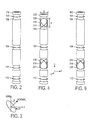
- a resistivity tool subassembly 102 is shown.
- the subassembly 102 is provided with one or more regions 106 of reduced diameter.
- a wire coil 104 is placed in the region 106 and spaced away from the surface of subassembly 102 by a constant distance.
- a non-conductive filler material such as epoxy, rubber, or ceramics may be used in the reduced diameter regions 106.
- Coil 104 is a transmitter coil, and coils 110 and 112 are receiving coils. In operation, transmitter coil 104 transmits an interrogating electromagnetic signal which propagates through the wellbore and surrounding formation.
- Receiver coils 110, 112 detect the interrogating electromagnetic signal and provide a measure of the electromagnetic signal's amplitude attenuation and phase shift between coils 110 and 112. From the amplitude attenuation and phase shift, the resistivity of the formation can be estimated using conventional techniques.
- the amplitude and phase shift information may be used in accordance with conventional techniques to estimate the distance to the nearest boundary layer.
- a second transmitter coil 108 may be added to the subassembly to provide additional resistivity measurements.
- the signal measurements from two (or more) different transmitter-receiver coil spacings provide enough information to determine formation resistivity and the distance to any nearby boundary layer.
- the first transmitter 104 may be spaced approximately 30 inches from the last receiver coil 112.
- the transmitter and receiver coils may comprise as little as one loop of wire, although more loops may provide additional signal power.
- the distance between the coils and the tool surface is preferably in the range from 1/16 inch to 3/4 inch, but may be larger.
- the equations used to determine resistivity and distance to the boundary layer can be derived by performing numerical modeling for the tool geometry in various locations relative to a boundary between materials of differing resistivities. Alternatively, the equations can be determined empirically. Both techniques are commonly employed by those in the art.
- the borehole is preferably steered away from bed boundaries to avoid straying into an adjacent shale bed and thereby keep the borehole in a target pay zone. Since the coils in Figure 2 are co-axial to the subassembly 102, the coil configuration of subassembly 102 is unable to provide this information. This coil configuration lacks azimuthal sensitivity.
- Figure 3 shows a coordinate system having one coordinate axis along the axis of the resistivity tool, and a second coordinate axis pointing from the tool axis to the tool face scribe line (defined earlier during the discussion of MWD sensors).
- the azimuth is defined as the angle from the tool scribe line.
- the wire coils discussed herein are approximately planar, i.e. they reside in a flat plane. The orientation of a plane (and hence, the coils) can be described by a vector perpendicular to the plane. This perpendicular vector is called a "normal" vector.
- Figure 3 shows a coil having a normal vector at a skew angle ⁇ from the tool axis and an azimuth angle of ⁇ .
- the azimuth angle ⁇ can be found by projecting the normal vector into a plane perpendicular to the tool axis. The projection is shown as a dashed arrow in Figure 3 .
- Figure 4 shows a resistivity tool 202 which can measure azimuthal resistivity variations.
- coil 110 is replaced by a first set of three skewed coils 216, 218, 220 located at the same position along the length of resistivity tool 202.
- the three skewed coils are oriented at a skew angle ⁇ from the tool axis.
- the three skewed coils are preferably provided with equally spaced azimuth angles ⁇ (e.g. 0°, 120°, and 240°). Non-equally spaced azimuthal angles can also be employed.
- the skew angle ⁇ is chosen to be 54.74° so that the normal vectors of skewed coils 216, 218, and 220 are perpendicular to each other.
- the three skewed coils 216, 218, and 220 are preferably employed as receiver coils as discussed further below.
- a second set of three skewed coils 208, 210, 212 may also be provided on resistivity tool 202. If included, skewed coils 208, 210, 212 are preferably employed as transmitter coils in place of coil 104. Preferably the second set of skewed coils 208, 210, 212 is azimuthally positioned to line up with the first set of skewed coils 220, 218, and 216, respectively, and are each oriented at a skew angle of ⁇ with respect to the resistivity tool axis. In other words, the pairs of skewed coils are skewed towards each other.
- the skewed coils may be constructed similarly to the coils of Figure 2 , that is, they may be placed in a recessed region of tool 202 and uniformly spaced away from the surface of tool 202 by a constant distance.
- the azimuthal sensitivity may be achieved by skewing either the transmitter coils or the receiver coils. It is not strictly necessary to have both transmitter and receiver coils skewed, although this latter configuration is presently preferred.
- the signals received by the set of skewed receiver coils 218, 216, 220, can be expressed as a linear combination of signals received by three virtual receiver coils R L , R Z , and R T .
- the signals received at skewed receiver coils R 1 , R 2 , R 3 must be manipulated to derive signals that would have been received at the three (non-existent) virtual receiver coils R L , R Z , R T if these coils actually existed.
- S R 1 S R L cos ⁇ + S R Z sin ⁇
- R 2 S R L cos ⁇ + S R Z cos 120 ⁇ ° + S R T sin 120 ⁇ ° sin ⁇
- R 3 S R L cos ⁇ + S R Z cos 240 ⁇ ° + S R T sin 240 ⁇ ° sin ⁇
- ⁇ is the skew angle of the actual receivers R 1 , R 2 and R 3
- S(R 1 ) is the signal received by receiver R 1 .
- This method of creating virtual coils is not limited to receivers.
- Virtual transmitters can also be emulated by combining the excitations of a set of actual transmitters.
- Signals transmitted by the set of skewed transmitter coils 210, 208, 212, (respectively referred to hereafter as T 1 , T 2 , T 3 ) can be expressed as a linear combination of the signals transmitted by three virtual transmitters T L , T Z , T T .
- S T 1 S T L cos ⁇ + S T Z sin ⁇
- S T 2 S T L cos ⁇ + S T Z cos 120 ⁇ ° + S T T sin 120 ⁇ ° sin ⁇
- S T 3 S T L cos ⁇ + S T Z cos 240 ⁇ ° + S T T sin 240 ⁇ ° sin ⁇ where ⁇ is the skew angle of the actual transmitters T 1 , T 2 and T 3 .
- FIG. 2 and 4 an example is hereby provided to illustrate the operation of resistivity tool 202 and to show how the measurements of resistivity tool 102 can be duplicated by resistivity tool 202.
- the set of transmitter coils T 1 , T 2 and T 3 is used to synthesize a virtual transmitter T L to replace transmitter 104, transmitter coil 108 (hereafter T 4 ) remains the same, the set of receiver coils R 1 , R 2 , R 3 is used to synthesize a virtual receiver R L to replace receiver 110, and receiver coil 112 (hereafter R 4 ) remains unchanged.
- resistivity tool 102 measures formation resistivity by comparing the signals induced in the receiver coils by a single transmitter. (The first and second transmitters are used separately to obtain different resistivity measurement depths.)
- the attenuation and phase difference between the received signals are known functions of the formation resistivity in a homogeneous formation. They can be used independently to measure the resistivity. In an anisotropic formation, the phase difference and attenuation measurements can be combined to determine both the horizontal and vertical resistivities.
- Resistivity tool 202 may employ these conventional techniques in conjunction with the synthesis equations derived above to duplicate the functionality of resistivity tool 102. More important, however, is the versatility and added functionality provided by tool 202.
- the uniformity, or "homogeneity" of a formation may be used as an indicator of the proximity of a bed boundary. Homogeneity can be determined by synthesizing virtual coil responses S(R Z ,T L ) and S(R T ,T L ). In a homogeneous formation, these signals are zero. Non-negligible signal measurements indicate the presence of a nearby bed boundary.
- S(R Z ,T L ) and S(R T ,T L ) equal zero.
- S(R T ,T L ) will be negligible and the amplitude of S(R Z ,T L ) may be used to estimate the distance to the boundary.
- the phase of S(R Z ',T L ) can be used to resolve the 180° ambiguity, and the maximized magnitude of S(R Z ',T L ) may be used to estimate the distance to the bed boundary.
- Another method for determining the direction of the boundary is to measure the azimuthal resistivities, and then form a direction vector from the measurements.
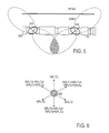
- Figure 5 shows a first order approximation of the gain patterns for transmitter T 1 (210) and receiver R 1 (218).
- the shaded overlap region is the region which most affects the resistivity measurement of signal S(R 1 ,T 1 ).
- receiver coil 112 may be used to determine an attenuation and phase difference if accurate quantitative measurements are desired.
- the relative amplitude and phase of measured signals S(R 4 ,T 1 ) and S(R 1 ,T 1 ) may be used to form estimates of azimuthal resistivity with better accuracy than may be achieved from S(R 1 ,T 1 ) alone.
- Azimuthal sensitivities can also be obtained for any azimuthal angle using the virtual response synthesis method.
- the amplitude of the synthesized response S(R ⁇ ,T ⁇ ) is then indicative of the resistivity in the desired ⁇ direction.
- the skew angle ⁇ is changed somewhat, but this effect may be empirically compensated or ignored.
- S R 60 ⁇ T 60 S R 1 ⁇ T 1 + S R 1 ⁇ T 2 + S R 2 ⁇ T 1 + S R 2 ⁇ T 2
- S R 300 ⁇ T 300 S R 1 ⁇ T 1 + S R 1 ⁇ T 3 + S R 3 ⁇ T 1 + S R 3 ⁇ T 3
- these equations provide azimuthal resistivity measurements in six equally spaced directions. These six measurements can be processed to give a directional vector indicating the direction of a nearby boundary.
- Direction ⁇ 0 ⁇ cos ⁇ ° + ⁇ 60 ⁇ cos 60 ⁇ ° + ⁇ 120 ⁇ cos 120 ⁇ ° + ⁇ 180 ⁇ cos 180 ⁇ ° + ⁇ 240 ⁇ cos 240 ⁇ ° + ⁇ 300 ⁇ cos 300 ⁇ ° ⁇ i ⁇ + ⁇ 0 ⁇ sin ⁇ ° + ⁇ 60 ⁇ sin 60 ⁇ ° + ⁇ 120 ⁇ sin 120 ⁇ ° + ⁇ 180 ⁇ sin 180 ⁇ ° + ⁇ 240 ⁇ sin 240 ⁇ ° + ⁇ 300 ⁇ sin 300 ⁇ ° ⁇ j ⁇
- a variety of ways may be used for estimating the distance to the bed boundary. or example, the change in apparent resistivity (derived from S(R L ,T L )) can be used to estimate the distance. Alternatively, the magnitude of the Direction vector defined above can be used to estimate the distance.
- the apparent resistivity at various distances from the tool can be measured.
- the difference in apparent resistivities for the different receiver-transmitter configurations can be used to provide estimates of the distances D 1 , D 2 (and angle of approach) to the bed boundary. To increase the reliability of this estimate, the rate of change of the apparent resistivities can be tracked for additional information.
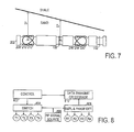
- FIG. 8 shows a functional block diagram of the electronics for resistivity tool 202.
- the electronics include a control module 802 which is coupled to an analog switch 804.
- Analog switch 804 is configured to drive any one of the transmitter coils T 1 , T 2 , T 3 , T 4 with a high frequency signal from radio-frequency signal source 806.
- the control module 802 preferably selects a transmitter coil, pauses long enough for transients to die out, then signals data storage/transmit module 810 to accept an amplitude and phase sample of the signals received by each of the receivers.
- the control module 802 preferably repeats this process sequentially for each of the transmitters.
- the amplitude and phase shift values are provided by amplitude and phase shift detector 808 which is coupled to each of the receiver coils R 1 , R 2 , R 3 ,
- the S(R i ,T i ) amplitude and phase samples are transmitted to the surface for processing to determine (i) formation resistivity, (ii) distance to nearest bed boundary, (iii) direction of nearest bed boundary, and (iv) resistivity of any nearby adjacent beds.
- the data storage/transmitter module 810 may be coupled to signaling unit 35 ( Figure 1 ) to transmit signal measurements to the surface.
- Signaling unit 35 can use any of several known techniques for transmitting information to the surface, including but not limited to (1) mud pressure pulse; (2) hard-wire connection; (3) acoustic wave; and (4) electromagnetic waves.
- Figure 10 shows the phase of S(R 1 ,T 1 ) relative to the transmitted signal.
- the phase is shown as a function of distance from a bed boundary between a homogeneous 1 ⁇ m medium (e.g. shale) and a homogeneous 10 ⁇ m medium (e.g. sandstone).
- the transmitter and receiver are spaced 40 inches apart, and a 0.5 MHz signal is used.
- Figure 11 shows the phase difference between S(R 1 ,T 1 ) and S(R 180 ,T 180 ) as a function of distance from a bed boundary, with the same conditions as before.
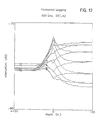
- Figure 12 shows the amplitude of S(R 1 ,T 1 ) relative to the amplitude of the transmitted signal as a function of distance from a bed boundary, with the same conditions as before. Close scrutiny reveals that with the tool in the sandstone, the signal amplitude can theoretically be used to observe the boundary from over 60 inches away.
- Figure 13 shows the amplitude of S(R 1 ,T 1 ) relative to S(R 180 ,T 180 ) as a function of distance from a bed boundary, with the same conditions as before.
- the investigation depth of the signal S(R j ,T i ) is determined not only by the transmitter-receiver spacing, but also by the skew angle ⁇ of the antenna coils.
- Virtual antennas with digitally variable skew angles can be synthesized by taking a suitable combination of T L and T Z or T T components. This may be a method for creating sensitive coil configurations if mechanical considerations prevent the coils from being mounted at the desired skew angles.
- FIG. 9 shows a resistivity tool 302 with an alternate configuration.
- an actual transmitter coil 104 serves as transmitter T L .
- S R T ⁇ T L S R 2 ⁇ T L - S R 3 ⁇ T L / sqrt 3 sin ⁇
- a homogeneous formation i.e.
- S(R Z ,T L ) and S(R T ,T T ) equal zero.
- S(R T ,T L ) will be negligible and the amplitude of S(R Z ,T L ) may be used to estimate the distance to the boundary.
- the magnitude of S(R Z ',T L ) may be used to estimate the distance to the bed boundary.
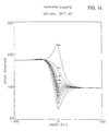
- Figure 14 shows the phase of S(R 1 ,T L ) relative to the transmitted signal as a function of distance from a bed boundary. Note that in this and the following graphs, only the receiver coil orientation changes as the skew angle ⁇ is changed. The other conditions remain the same. Again, the phase can be used to observe the boundary from over 40 inches away.
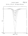
- Figure 15 shows the phase difference between S(R 1 ,T L ) and S(R 180 ,T L ) as a function of distance from a bed boundary, with the same conditions as before.
- the coils skewed at the larger skew angles are more phase sensitive to the boundary presence.
- the signal amplitude is also decreased at the larger skew angles, so a compromise angle of about 60° may be preferred.
- Figure 16 shows the amplitude of S(R 1 ,T L ) relative to the amplitude of the transmitted signal as a function of distance from a bed boundary, with the same conditions as before. Close scrutiny reveals that with the tool in the sandstone, the signal amplitude can theoretically be used to observe the boundary from over 50 inches away. The previously mentioned heavy attenuation of signals at increased skew angles is evident here.
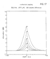
- Figure 17 shows the amplitude of S(R 1 ,T L ) relative to S(R 180 ,T L ) as a function of distance from a bed boundary, with the same conditions as before.
- the coils skewed at larger angles exhibit the greatest sensitivity to the boundary, but signal power considerations may limit the skew angles to about 60° or less.
- An azimuthally tunable resistivity tool has been disclosed. This tool can be used to detect the presence of an adjacent bed and to estimate its proximity by measuring formation resistivity azimuthally.
- Figure 5 shows a borehole in a sand layer below a more conductive shale bed. The apparent resistivity measured upward is lower than the resistivity measured downward. The difference between the upward and downward resistivity measurements can be used to detect the adjacent conductive bed and estimate the distance to the bed interface. The azimuthal direction of the minimum and maximum measured resistivities can then be used to determine the direction of the bed interface.
- An azimuthally tunable resistivity tool for use in a borehole having a borehole axis, wherein the tool comprises: at least one transmitter antenna configured to transmit a radio-frequency signal; and at least three receiver antennas configured to receive the radio-frequency signal, wherein the receiver antennas are each oriented at a skew angle from the borehole axis, and wherein the receiver antennas are oriented in differing azimuthal directions.
- the one or more virtual receivers includes a virtual receiver oriented with a skew angle of 0°.
- the one or more virtual receivers includes a virtual receiver oriented with a skew angle of 90°.
- the one or more virtual receivers includes a virtual receiver oriented with an azimuthal direction different than any of the at least three receiver antennas.
- An azimuthally tunable resistivity tool for use in a borehole having a borehole axis, wherein the tool comprises: at least three transmitter antennas configured to transmit a radio frequency signal, wherein the transmitter antennas are each oriented at a skew angle from the borehole axis, and wherein the transmitter antennas are oriented in differing azimuthal directions; and at least one receiver antenna configured to receive the radio-frequency signal.
- the one or more virtual transmitter antennas includes a virtual transmitter antenna oriented with a skew angle of 0°.
- the one or more virtual transmitter antennas includes a virtual transmitter antenna oriented with a skew angle of 90°.
- the one or more virtual transmitter antennas includes a virtual transmitter antenna oriented with an azimuthal direction different than any of the at least three transmitter antennas.
- the tool of embodiment 14, further comprising: a reference receiver antenna oriented with a skew angle of 0°, wherein signals from the reference receiver antenna are used to determine a phase difference and relative attenuation of signals from the at least one receiver antenna.
- a method for detecting the location of a bed boundary relative to a borehole comprises: generating a first signal representing a first azimuthally sensitive measurement of phase shift and attenuation of an electromagnetic signal propagating through a formation around a borehole; generating a second signal representing a second azimuthally sensitive measurement of phase shift and attenuation of an electromagnetic signal propagating through the formation around a borehole, wherein the azimuthal sensitivity of the first measurement is in a direction different than that of the second measurement; determining a virtual antenna orientation having a maximized signal amplitude synthesized from the first and second signals; combining the virtual antenna orientation with a synthesized phase shift to determine a bed boundary direction from the borehole.
- the method of embodiment 25, wherein the generating of the first and second signals includes: receiving electromagnetic signals transmitted from first and second skewed transmitter antennas respectively oriented in first and second azimuthal directions.
- the method of embodiment 25, wherein the generating of the first and second signals includes: receiving a transmitted electromagnetic signal on first and second skewed receiver antennas respectively oriented in first and second azimuthal directions.
- the method of embodiment 25, further comprising: using the maximized signal amplitude to estimate a distance to the bed boundary.
- the method of embodiment 25, further comprising: combining the first and second signals to obtain an azimuthally-insensitive measurement of phase shift and attenuation; estimating a distance to the bed boundary from the azimuthally-insensitive measurement.
- a first method for performing azimuthally tunable resistivity measurements comprises: transmitting an electromagnetic signal which propagates through a formation surrounding a borehole; measuring one or more characteristics of the electromagnetic signal using three skewed receiver antennas, wherein the skewed receiver antennas are oriented in equally spaced azimuthal directions; combining the skewed receiver measurements to form a desired virtual receiver measurement, wherein the desired virtual receiver has a desired skew angle and a desired azimuthal direction.
- a second method for performing azimuthally tunable resistivity measurements comprises: using three skewed transmitter antennas oriented in equally spaced azimuthal directions to transmit electromagnetic signals which propagate through a formation surrounding a borehole; using a receiver antenna to measure one or more characteristics of the electromagnetic signals; combining the measurements to form a receiver measurement of characteristics of electromagnetic signals transmitted by a desired virtual transmitter, wherein the desired virtual transmitter has a desired skew angle and a desired azimuthal direction.
Landscapes
- Physics & Mathematics (AREA)
- Life Sciences & Earth Sciences (AREA)
- Engineering & Computer Science (AREA)
- Geology (AREA)
- Mining & Mineral Resources (AREA)
- General Life Sciences & Earth Sciences (AREA)
- Environmental & Geological Engineering (AREA)
- Geophysics (AREA)
- Remote Sensing (AREA)
- Electromagnetism (AREA)
- Fluid Mechanics (AREA)
- Geochemistry & Mineralogy (AREA)
- General Physics & Mathematics (AREA)
- Geophysics And Detection Of Objects (AREA)
- Testing Or Measuring Of Semiconductors Or The Like (AREA)
- Measurement Of Resistance Or Impedance (AREA)
Applications Claiming Priority (2)
| Application Number | Priority Date | Filing Date | Title |
|---|---|---|---|
| US09/255,621 US6181138B1 (en) | 1999-02-22 | 1999-02-22 | Directional resistivity measurements for azimuthal proximity detection of bed boundaries |
| EP00911755.7A EP1163539B1 (de) | 1999-02-22 | 2000-02-10 | Richtungsabhängige wiederstandsvermessungen für azimuthale nähefeststellung von schicht grenzen. |
Related Parent Applications (3)
| Application Number | Title | Priority Date | Filing Date |
|---|---|---|---|
| EP00911755.7A Division EP1163539B1 (de) | 1999-02-22 | 2000-02-10 | Richtungsabhängige wiederstandsvermessungen für azimuthale nähefeststellung von schicht grenzen. |
| EP00911755.7A Division-Into EP1163539B1 (de) | 1999-02-22 | 2000-02-10 | Richtungsabhängige wiederstandsvermessungen für azimuthale nähefeststellung von schicht grenzen. |
| EP00911755.7 Division | 2000-02-10 |
Publications (3)
| Publication Number | Publication Date |
|---|---|
| EP2629122A2 true EP2629122A2 (de) | 2013-08-21 |
| EP2629122A3 EP2629122A3 (de) | 2013-09-04 |
| EP2629122B1 EP2629122B1 (de) | 2016-04-13 |
Family
ID=22969160
Family Applications (2)
| Application Number | Title | Priority Date | Filing Date |
|---|---|---|---|
| EP13167569.6A Expired - Lifetime EP2629122B1 (de) | 1999-02-22 | 2000-02-10 | Direktionale Widerstandsmessungen für azimuthale Näherungserkennung von Schichtgrenzen |
| EP00911755.7A Expired - Lifetime EP1163539B1 (de) | 1999-02-22 | 2000-02-10 | Richtungsabhängige wiederstandsvermessungen für azimuthale nähefeststellung von schicht grenzen. |
Family Applications After (1)
| Application Number | Title | Priority Date | Filing Date |
|---|---|---|---|
| EP00911755.7A Expired - Lifetime EP1163539B1 (de) | 1999-02-22 | 2000-02-10 | Richtungsabhängige wiederstandsvermessungen für azimuthale nähefeststellung von schicht grenzen. |
Country Status (5)
| Country | Link |
|---|---|
| US (1) | US6181138B1 (de) |
| EP (2) | EP2629122B1 (de) |
| CA (1) | CA2362542C (de) |
| NO (2) | NO334635B1 (de) |
| WO (1) | WO2000050926A1 (de) |
Cited By (2)
| Publication number | Priority date | Publication date | Assignee | Title |
|---|---|---|---|---|
| WO2015084600A1 (en) * | 2013-12-05 | 2015-06-11 | Baker Hughes Incorporated | Dual mode balancing in obm resistivity imaging |
| EP3523503A4 (de) * | 2016-10-04 | 2019-10-02 | Halliburton Energy Services, Inc. | Abstimmbares dipolmoment für formationsmessungen |
Families Citing this family (153)
| Publication number | Priority date | Publication date | Assignee | Title |
|---|---|---|---|---|
| US20040239521A1 (en) | 2001-12-21 | 2004-12-02 | Zierolf Joseph A. | Method and apparatus for determining position in a pipe |
| US6476609B1 (en) * | 1999-01-28 | 2002-11-05 | Dresser Industries, Inc. | Electromagnetic wave resistivity tool having a tilted antenna for geosteering within a desired payzone |
| US7659722B2 (en) * | 1999-01-28 | 2010-02-09 | Halliburton Energy Services, Inc. | Method for azimuthal resistivity measurement and bed boundary detection |
| US6163155A (en) * | 1999-01-28 | 2000-12-19 | Dresser Industries, Inc. | Electromagnetic wave resistivity tool having a tilted antenna for determining the horizontal and vertical resistivities and relative dip angle in anisotropic earth formations |
| EP1195011A4 (de) | 1999-12-02 | 2005-02-02 | Electromagnetic Instr Inc | Komponentenfeldantenne für induktionsbohrlochmessgeräte |
| US6353321B1 (en) * | 2000-01-27 | 2002-03-05 | Halliburton Energy Services, Inc. | Uncompensated electromagnetic wave resistivity tool for bed boundary detection and invasion profiling |
| AU754992B2 (en) * | 2000-03-20 | 2002-11-28 | Schlumberger Holdings Limited | A downhole tool including an electrically steerable antenna for use with a formation deployed remote sensing unit |
| US6788065B1 (en) * | 2000-10-12 | 2004-09-07 | Schlumberger Technology Corporation | Slotted tubulars for subsurface monitoring in directed orientations |
| US6573722B2 (en) | 2000-12-15 | 2003-06-03 | Schlumberger Technology Corporation | Method and apparatus for cancellation of borehole effects due to a tilted or transverse magnetic dipole |
| US6651739B2 (en) * | 2001-02-21 | 2003-11-25 | The United States Of America As Represented By The Administrator Of The National Aeronautics And Space Administration | Medium frequency pseudo noise geological radar |
| EP1373938A4 (de) * | 2001-04-06 | 2005-01-12 | Halliburton Energy Serv Inc | Verfahren und vorrichtung zur bestimmung der hohen seite eines bohrstrangs während gamma-mbd-operationen und zum korrelieren von gammaereignissen damit |
| US6725161B1 (en) * | 2001-04-26 | 2004-04-20 | Applied Minds, Inc. | Method for locating and identifying underground structures with horizontal borehole to surface tomography |
| US8296113B2 (en) * | 2001-05-18 | 2012-10-23 | Halliburton Energy Services, Inc. | Virtual steering of induction tool attenuation and phase difference measurements |
| US7227363B2 (en) * | 2001-06-03 | 2007-06-05 | Gianzero Stanley C | Determining formation anisotropy based in part on lateral current flow measurements |
| US6958610B2 (en) | 2001-06-03 | 2005-10-25 | Halliburton Energy Services, Inc. | Method and apparatus measuring electrical anisotropy in formations surrounding a wellbore |
| US6584408B2 (en) | 2001-06-26 | 2003-06-24 | Schlumberger Technology Corporation | Subsurface formation parameters from tri-axial measurements |
| AU2002330989A1 (en) * | 2001-08-03 | 2003-04-01 | Baker Hughes Incorporated | A method and apparatus for a multi-component induction instrumentmeasuring system |
| GB2383133A (en) * | 2001-08-07 | 2003-06-18 | Statoil Asa | Investigation of subterranean reservoirs |
| GB2378511B (en) * | 2001-08-07 | 2005-12-28 | Statoil Asa | Method and apparatus for determining the nature of subterranean reservoirs |
| US6556016B2 (en) * | 2001-08-10 | 2003-04-29 | Halliburton Energy Services, Inc. | Induction method for determining dip angle in subterranean earth formations |
| US6969994B2 (en) * | 2001-09-26 | 2005-11-29 | Schlumberger Technology Corporation | Directional electromagnetic measurements insensitive to dip and anisotropy |
| US6556015B1 (en) * | 2001-10-11 | 2003-04-29 | Schlumberger Technology Corporation | Method and system for determining formation anisotropic resistivity with reduced borehole effects from tilted or transverse magnetic dipoles |
| US6774628B2 (en) * | 2002-01-18 | 2004-08-10 | Schlumberger Technology Corporation | Nuclear magnetic resonance imaging using phase encoding with non-linear gradient fields |
| US7375530B2 (en) * | 2002-03-04 | 2008-05-20 | Baker Hughes Incorporated | Method for signal enhancement in azimuthal propagation resistivity while drilling |
| US7463035B2 (en) * | 2002-03-04 | 2008-12-09 | Baker Hughes Incorporated | Method and apparatus for the use of multicomponent induction tool for geosteering and formation resistivity data interpretation in horizontal wells |
| US6998844B2 (en) * | 2002-04-19 | 2006-02-14 | Schlumberger Technology Corporation | Propagation based electromagnetic measurement of anisotropy using transverse or tilted magnetic dipoles |
| US6794875B2 (en) * | 2002-05-20 | 2004-09-21 | Halliburton Energy Services, Inc. | Induction well logging apparatus and method |
| GB2385923B (en) * | 2002-05-24 | 2004-07-28 | Statoil Asa | System and method for electromagnetic wavefield resolution |
| US7038457B2 (en) * | 2002-07-29 | 2006-05-02 | Schlumberger Technology Corporation | Constructing co-located antennas by winding a wire through an opening in the support |
| US6903553B2 (en) * | 2002-09-06 | 2005-06-07 | Baker Hughes Incorporated | Method and apparatus for a quadrupole transmitter for directionally sensitive induction tool |
| US6898967B2 (en) * | 2002-09-09 | 2005-05-31 | Baker Hughes Incorporated | Azimuthal resistivity using a non-directional device |
| US7345487B2 (en) * | 2002-09-25 | 2008-03-18 | Halliburton Energy Services, Inc. | Method and system of controlling drilling direction using directionally sensitive resistivity readings |
| US7098858B2 (en) * | 2002-09-25 | 2006-08-29 | Halliburton Energy Services, Inc. | Ruggedized multi-layer printed circuit board based downhole antenna |
| US6810331B2 (en) * | 2002-09-25 | 2004-10-26 | Halliburton Energy Services, Inc. | Fixed-depth of investigation log for multi-spacing multi-frequency LWD resistivity tools |
| US6819111B2 (en) * | 2002-11-22 | 2004-11-16 | Baker Hughes Incorporated | Method of determining vertical and horizontal resistivity, and relative dip in anisotropic earth formations having an arbitrary electro-magnetic antenna combination and orientation with additional rotation and position measurements |
| US6937021B2 (en) * | 2002-12-09 | 2005-08-30 | Schlumberger Technology Corporation | Method and apparatus for determining the presence and orientation of a fraction in an earth formation |
| US6924646B2 (en) * | 2002-12-31 | 2005-08-02 | Schlumberger Technology Corporation | System and method for locating a fracture in an earth formation |
| GB2399640B (en) | 2003-03-17 | 2007-02-21 | Statoil Asa | Method and apparatus for determining the nature of submarine reservoirs |
| US6816787B2 (en) * | 2003-03-31 | 2004-11-09 | Schlumberger Technology Corporation | Generating and displaying a virtual core and a virtual plug associated with a selected piece of the virtual core |
| US7382135B2 (en) * | 2003-05-22 | 2008-06-03 | Schlumberger Technology Corporation | Directional electromagnetic wave resistivity apparatus and method |
| US7286091B2 (en) | 2003-06-13 | 2007-10-23 | Schlumberger Technology Corporation | Co-located antennas |
| US7557581B2 (en) * | 2003-11-05 | 2009-07-07 | Shell Oil Company | Method for imaging subterranean formations |
| US7425830B2 (en) * | 2003-11-05 | 2008-09-16 | Shell Oil Company | System and method for locating an anomaly |
| US7538555B2 (en) * | 2003-11-05 | 2009-05-26 | Shell Oil Company | System and method for locating an anomaly ahead of a drill bit |
| US7046009B2 (en) * | 2003-12-24 | 2006-05-16 | Baker Hughes Incorporated | Method for measuring transient electromagnetic components to perform deep geosteering while drilling |
| GB2409900B (en) | 2004-01-09 | 2006-05-24 | Statoil Asa | Processing seismic data representing a physical system |
| US7385400B2 (en) * | 2004-03-01 | 2008-06-10 | Pathfinder Energy Services, Inc. | Azimuthally sensitive receiver array for an electromagnetic measurement tool |
| CA2499043C (en) * | 2004-03-01 | 2010-09-14 | Pathfinder Energy Services, Inc. | Azimuthally focused electromagnetic measurement tool |
| US7848887B2 (en) * | 2004-04-21 | 2010-12-07 | Schlumberger Technology Corporation | Making directional measurements using a rotating and non-rotating drilling apparatus |
| US7786733B2 (en) * | 2004-07-14 | 2010-08-31 | Schlumberger Technology Corporation | Apparatus and system for well placement and reservoir characterization |
| US7755361B2 (en) * | 2004-07-14 | 2010-07-13 | Schlumberger Technology Corporation | Apparatus and system for well placement and reservoir characterization |
| US8736270B2 (en) * | 2004-07-14 | 2014-05-27 | Schlumberger Technology Corporation | Look ahead logging system |
| EA010068B1 (ru) * | 2004-07-23 | 2008-06-30 | Шелл Интернэшнл Рисерч Маатсхаппий Б.В. | Способ создания изображения подземных пластов |
| US7471088B2 (en) * | 2004-12-13 | 2008-12-30 | Baker Hughes Incorporated | Elimination of the anisotropy effect in LWD azimuthal resistivity tool data |
| GB2422673B (en) * | 2005-02-01 | 2010-03-24 | Electromagnetic Geoservices As | Optimum signal for sea bed logging |
| WO2006091487A1 (en) * | 2005-02-21 | 2006-08-31 | Baker Hughes Incorporated | Well placement by use of differences in electrical anisotropy of different layers |
| US7483793B2 (en) * | 2005-07-27 | 2009-01-27 | Baker Hughes Incorporated | Method of generating a deep resistivity image in LWD measurements |
| GB2434868B (en) | 2006-02-06 | 2010-05-12 | Statoil Asa | Method of conducting a seismic survey |
| GB2435693A (en) * | 2006-02-09 | 2007-09-05 | Electromagnetic Geoservices As | Seabed electromagnetic surveying |
| EA200870499A1 (ru) * | 2006-05-04 | 2009-04-28 | Шелл Интернэшнл Рисерч Маатсхаппий Б.В. | Способ выполнения анализа подземного пласта и способ добычи минерального углеводородного флюида, и машиночитаемый носитель |
| GB2439378B (en) * | 2006-06-09 | 2011-03-16 | Electromagnetic Geoservices As | Instrument for measuring electromagnetic signals |
| WO2007149106A1 (en) * | 2006-06-19 | 2007-12-27 | Halliburton Energy Services, Inc. | Antenna cutout in a downhole tubular |
| CN101501297B (zh) | 2006-07-11 | 2013-10-16 | 哈里伯顿能源服务公司 | 模块化地质导向工具组件 |
| WO2008008346A2 (en) | 2006-07-12 | 2008-01-17 | Halliburton Energy Services, Inc. | Method and apparatus for building a tilted antenna |
| US8593147B2 (en) | 2006-08-08 | 2013-11-26 | Halliburton Energy Services, Inc. | Resistivity logging with reduced dip artifacts |
| AU2007295028B2 (en) * | 2006-09-13 | 2011-12-15 | Exxonmobil Upstream Research Company | Rapid inversion of electromagnetic reconnaissance survey data |
| CN101536252B (zh) * | 2006-09-15 | 2012-12-05 | 哈里伯顿能源服务公司 | 用于井下器具的多轴天线和方法 |
| CN102928888A (zh) * | 2006-09-15 | 2013-02-13 | 哈里伯顿能源服务公司 | 用于井下器具的多轴天线和方法 |
| US7663372B2 (en) * | 2006-09-25 | 2010-02-16 | Baker Hughes Incorporated | Resistivity tools with collocated antennas |
| GB2442749B (en) | 2006-10-12 | 2010-05-19 | Electromagnetic Geoservices As | Positioning system |
| US8466683B2 (en) * | 2006-12-14 | 2013-06-18 | Schlumberger Technology Corporation | Determining properties of earth formations using the electromagnetic coupling tensor |
| US8274289B2 (en) * | 2006-12-15 | 2012-09-25 | Halliburton Energy Services, Inc. | Antenna coupling component measurement tool having rotating antenna configuration |
| GB2445582A (en) | 2007-01-09 | 2008-07-16 | Statoil Asa | Method for analysing data from an electromagnetic survey |
| US8378908B2 (en) * | 2007-03-12 | 2013-02-19 | Precision Energy Services, Inc. | Array antenna for measurement-while-drilling |
| US8049508B2 (en) * | 2007-03-16 | 2011-11-01 | Baker Hughes Incorporated | Method and apparatus for determining formation boundary near the bit for conductive mud |
| BRPI0711465B1 (pt) * | 2007-03-16 | 2018-04-24 | Halliburton Energy Services, Inc. | ferramenta de perfilagem, e, método para ferramenta de perfilagem de resistividade azimutalmente sensível |
| US7759940B2 (en) * | 2007-04-04 | 2010-07-20 | Baker Hughes Incorporated | Mutual shielding of collocated induction coils in multi-component induction logging instruments |
| US8120361B2 (en) * | 2008-11-10 | 2012-02-21 | Cbg Corporation | Azimuthally sensitive resistivity logging tool |
| GB2462975A (en) * | 2007-07-03 | 2010-03-03 | Shell Int Research | System and method for measuring a time-varying magnetic field and method for production of a hydrocarbon fluid |
| US8129993B2 (en) * | 2007-07-10 | 2012-03-06 | Schlumberger Technology Corporation | Determining formation parameters using electromagnetic coupling components |
| US8547783B2 (en) * | 2007-12-12 | 2013-10-01 | Exxonmobil Upstream Research Company | Method and apparatus for evaluating submarine formations |
| AU2008348131B2 (en) * | 2008-01-18 | 2011-08-04 | Halliburton Energy Services, Inc. | EM-guided drilling relative to an existing borehole |
| RU2362012C1 (ru) * | 2008-01-21 | 2009-07-20 | Общество с ограниченной ответственностью Научно-производственная фирма "ВНИИГИС-Забойные телеметрические комплексы" (ООО НПФ "ВНИИГИС-ЗТК") | Устройство для контроля положения ствола горизонтальной скважины |
| US10119377B2 (en) * | 2008-03-07 | 2018-11-06 | Weatherford Technology Holdings, Llc | Systems, assemblies and processes for controlling tools in a well bore |
| US9194227B2 (en) | 2008-03-07 | 2015-11-24 | Marathon Oil Company | Systems, assemblies and processes for controlling tools in a wellbore |
| WO2009151937A2 (en) * | 2008-05-27 | 2009-12-17 | Shell Oil Company | Layer stripping method |
| US8193813B2 (en) * | 2008-06-11 | 2012-06-05 | Schlumberger Technology Corporation | Measurement of formation parameters using rotating directional EM antenna |
| AU2009318042B2 (en) | 2008-11-24 | 2013-11-14 | Halliburton Energy Services, Inc. | A high frequency dielectric measurement tool |
| AU2008365630B2 (en) | 2008-12-16 | 2012-05-03 | Halliburton Energy Services, Inc. | Azimuthal at-bit resistivity and geosteering methods and systems |
| US8207738B2 (en) * | 2009-03-24 | 2012-06-26 | Smith International Inc. | Non-planar antennae for directional resistivity logging |
| US8089268B2 (en) * | 2009-03-24 | 2012-01-03 | Smith International, Inc. | Apparatus and method for removing anisotropy effect from directional resistivity measurements |
| US8487625B2 (en) * | 2009-04-07 | 2013-07-16 | Baker Hughes Incorporated | Performing downhole measurement using tuned transmitters and untuned receivers |
| US9134449B2 (en) * | 2009-05-04 | 2015-09-15 | Schlumberger Technology Corporation | Directional resistivity measurement for well placement and formation evaluation |
| WO2011139761A2 (en) | 2010-04-29 | 2011-11-10 | Schlumberger Canada Limited | Gain-corrected measurements |
| US8368403B2 (en) * | 2009-05-04 | 2013-02-05 | Schlumberger Technology Corporation | Logging tool having shielded triaxial antennas |
| US8159227B2 (en) * | 2009-05-11 | 2012-04-17 | Smith International Inc. | Methods for making directional resistivity measurements |
| US7990153B2 (en) * | 2009-05-11 | 2011-08-02 | Smith International, Inc. | Compensated directional resistivity measurements |
| WO2011022012A1 (en) | 2009-08-20 | 2011-02-24 | Halliburton Energy Services, Inc. | Fracture characterization using directional electromagnetic resistivity measurements |
| US8497673B2 (en) * | 2009-09-28 | 2013-07-30 | Schlumberger Technology Corporation | Directional resistivity antenna shield |
| US8466682B2 (en) * | 2009-09-29 | 2013-06-18 | Schlumberger Technology Corporation | Apparatus and method for downhole electromagnetic measurement while drilling |
| US8860416B2 (en) | 2009-10-05 | 2014-10-14 | Halliburton Energy Services, Inc. | Downhole sensing in borehole environments |
| WO2011043851A1 (en) | 2009-10-05 | 2011-04-14 | Halliburton Energy Services, Inc. | Deep evaluation of resistive anomalies in borehole environments |
| WO2011043764A1 (en) | 2009-10-05 | 2011-04-14 | Halliburton Energy Services, Inc. | Integrated geomechanics determinations and wellbore pressure control |
| US9140817B2 (en) * | 2009-10-08 | 2015-09-22 | Precision Energy Services, Inc. | Steerable magnetic dipole antenna for measurement-while-drilling applications |
| US9366780B2 (en) | 2009-10-08 | 2016-06-14 | Precision Energy Services, Inc. | Steerable magnetic dipole antenna for measurement while drilling applications |
| US8471563B2 (en) * | 2009-10-08 | 2013-06-25 | Precision Energy Services, Inc. | Steerable magnetic dipole antenna for measurement while drilling applications |
| US8604796B2 (en) * | 2009-10-08 | 2013-12-10 | Precision Energy Services, Inc. | Steerable magnetic dipole antenna for measurement-while-drilling applications |
| AU2010343292B2 (en) | 2010-01-22 | 2014-10-16 | Halliburton Energy Services Inc. | Method and apparatus for resistivity measurements |
| US8680865B2 (en) * | 2010-03-19 | 2014-03-25 | Schlumberger Technology Corporation | Single well reservoir imaging apparatus and methods |
| US9588250B2 (en) * | 2010-04-14 | 2017-03-07 | Baker Hughes Incorporated | Three-coil system with short nonconductive inserts for transient MWD resistivity measurements |
| US8850899B2 (en) | 2010-04-15 | 2014-10-07 | Marathon Oil Company | Production logging processes and systems |
| US9310508B2 (en) | 2010-06-29 | 2016-04-12 | Halliburton Energy Services, Inc. | Method and apparatus for sensing elongated subterranean anomalies |
| BR112013000526A2 (pt) * | 2010-07-09 | 2016-05-17 | Halliburton Energy Services Inc | aparelho, método, meio de armazenagem legível por máquina, e, método de analisar um reservatório subterrâneo |
| CA2802722C (en) | 2010-07-27 | 2023-04-04 | Exxonmobil Upstream Research Company | Inverting geophysical data for geological parameters or lithology |
| EP2606452A4 (de) | 2010-08-16 | 2017-08-16 | Exxonmobil Upstream Research Company | Reduzierung der dimensionalität des joint-inversion-problems |
| US9273517B2 (en) | 2010-08-19 | 2016-03-01 | Schlumberger Technology Corporation | Downhole closed-loop geosteering methodology |
| US8536871B2 (en) | 2010-11-02 | 2013-09-17 | Schlumberger Technology Corporation | Method of correcting resistivity measurements for toll bending effects |
| US8626446B2 (en) | 2011-04-01 | 2014-01-07 | Schlumberger Technology Corporation | Method of directional resistivity logging |
| EP2715603A4 (de) | 2011-06-02 | 2016-07-13 | Exxonmobil Upstream Res Co | Joint-inversion mit unbekannter lithologie |
| EP2721478A4 (de) | 2011-06-17 | 2015-12-02 | Exxonmobil Upstream Res Co | Einfrieren von domänen in einer verbindungsinversion |
| US9494711B2 (en) | 2011-07-21 | 2016-11-15 | Garrett M Leahy | Adaptive weighting of geophysical data types in joint inversion |
| US8854044B2 (en) | 2011-11-09 | 2014-10-07 | Haliburton Energy Services, Inc. | Instrumented core barrels and methods of monitoring a core while the core is being cut |
| US8797035B2 (en) | 2011-11-09 | 2014-08-05 | Halliburton Energy Services, Inc. | Apparatus and methods for monitoring a core during coring operations |
| US10823871B2 (en) | 2011-11-15 | 2020-11-03 | Halliburton Energy Services, Inc. | Enhanced resistivity measurement with at-bit resistivity sensor |
| CA2854440C (en) | 2011-11-15 | 2018-01-16 | Burkay Donderici | Look-ahead of the bit applications |
| US9429675B2 (en) * | 2012-03-27 | 2016-08-30 | Schlumberger Technology Corporation | Anisotropy processing in low angle wells |
| US9540922B2 (en) | 2012-03-29 | 2017-01-10 | Schlumberger Technology Corporation | Electromagnetic method for obtaining dip azimuth angle |
| EP2836860A4 (de) | 2012-06-25 | 2015-11-11 | Halliburton Energy Services Inc | Kippantennenmesssysteme und verfahren zur erzeugung von robusten messsignalen |
| CN102979519B (zh) * | 2012-12-14 | 2015-08-12 | 中国电子科技集团公司第二十二研究所 | 用于带倾斜线圈的电阻率设备的电阻率测量方法及装置 |
| BR112015011268A2 (pt) * | 2012-12-19 | 2017-07-11 | Halliburton Energy Services Inc | método, e, sistema para otimizar medidas de resistividade profunda |
| US10444396B2 (en) * | 2012-12-31 | 2019-10-15 | Halliburton Energy Services, Inc. | Deep azimuthal system with multi-pole sensors |
| CA2895022A1 (en) * | 2012-12-31 | 2014-07-03 | Halliburton Energy Services, Inc. | Formation imaging with multi-pole antennas |
| US9482776B2 (en) | 2013-02-07 | 2016-11-01 | Aramco Services Company | Interferometric processing to detect subterranean geological boundaries |
| US10591638B2 (en) | 2013-03-06 | 2020-03-17 | Exxonmobil Upstream Research Company | Inversion of geophysical data on computer system having parallel processors |
| US9846255B2 (en) | 2013-04-22 | 2017-12-19 | Exxonmobil Upstream Research Company | Reverse semi-airborne electromagnetic prospecting |
| MX2016005002A (es) | 2013-11-21 | 2016-12-16 | Halliburton Energy Services Inc | Monitoreo de frente de fluido a base de acoplamiento cruzado. |
| US20150268372A1 (en) * | 2014-03-20 | 2015-09-24 | Schlumberger Technology Corporation | Method and apparatus for determining formation properties using collocated triaxial antennas with non-planar sinusoidal coils |
| WO2016025170A1 (en) * | 2014-08-11 | 2016-02-18 | Halliburton Energy Services, Inc. | Probe assembly for performing electromagnetic field mapping around an antenna |
| EP3032284A1 (de) * | 2014-12-12 | 2016-06-15 | Services Pétroliers Schlumberger | System und Verfahren zur Kompensation bei einer Widerstandserkennung |
| WO2017069742A1 (en) | 2015-10-20 | 2017-04-27 | Halliburton Energy Services, Inc. | Soft magnetic bands for tilted coil antennas |
| US10550682B2 (en) | 2015-10-22 | 2020-02-04 | Micropulse, Llc. | Programmable integrated measurement while drilling directional controller |
| US20170114630A1 (en) * | 2015-10-22 | 2017-04-27 | MicroPulse, LLC | Integrated measurement while drilling directional controller |
| EP3337951B1 (de) | 2015-10-26 | 2023-11-29 | Halliburton Energy Services, Inc. | Ratiometrische frequenzverarbeitung von widerstandsprotokollierungswerkzeugdaten |
| US10324432B2 (en) | 2016-04-21 | 2019-06-18 | Baker Hughes, A Ge Company, Llc | Estimation of electromagnetic tool sensitivity range |
| US10161245B2 (en) | 2016-05-17 | 2018-12-25 | Saudi Arabian Oil Company | Anisotropy and dip angle determination using electromagnetic (EM) impulses from tilted antennas |
| US10605073B2 (en) | 2016-09-15 | 2020-03-31 | Shanjun Li | System and methodology of look ahead and look around LWD tool |
| CN107461191B (zh) * | 2017-08-03 | 2021-09-14 | 中石化石油工程技术服务有限公司 | 一种随钻方位电磁波边界探测仪器温度刻度方法 |
| US20190137647A1 (en) | 2017-11-06 | 2019-05-09 | Weatherford Technology Holdings, Llc | Method and Apparatus for Formation Evaluation |
| WO2019117873A1 (en) * | 2017-12-12 | 2019-06-20 | Halliburton Energy Services, Inc. | Component signal decoupling for multi-sub resistivity tool with spaced antennas |
| WO2020142079A1 (en) * | 2018-12-31 | 2020-07-09 | Halliburton Energy Services, Inc. | Antenna shield for co-located antennas in a wellbore |
| CN114846360B (zh) | 2019-10-28 | 2025-02-18 | 本奇特里集团有限责任公司 | 使用开槽点偶极子天线的电磁工具 |
| CN112487355B (zh) * | 2020-11-26 | 2024-09-10 | 中国海洋石油集团有限公司 | 一种随钻方位电磁波测井信号的处理方法和装置 |
| CN119914260B (zh) * | 2025-03-20 | 2025-10-14 | 中国地质科学院勘探技术研究所 | 电阻率测量短节及钻井装置 |
Citations (11)
| Publication number | Priority date | Publication date | Assignee | Title |
|---|---|---|---|---|
| US3237153A (en) | 1959-09-21 | 1966-02-22 | Schlumberger Well Surv Corp | Detection of acoustic signals |
| US3312934A (en) | 1963-07-12 | 1967-04-04 | Mobil Oil Corp | Measuring acoustic velocity over two travel paths |
| US3593255A (en) | 1969-05-29 | 1971-07-13 | Marathon Oil Co | Acoustic logging tool having opposed transducers |
| US4649525A (en) | 1981-12-08 | 1987-03-10 | Mobil Oil Corporation | Shear wave acoustic logging system |
| US4718046A (en) | 1985-11-22 | 1988-01-05 | Mobil Oil Corporation | Method for driving a bender-type transmitter of a borehole logging tool to sequentially produce acoustic compressional and tube waves |
| US4869349A (en) | 1988-11-03 | 1989-09-26 | Halliburton Logging Services, Inc. | Flexcompressional acoustic transducer |
| US5069308A (en) | 1990-11-13 | 1991-12-03 | The Board Of Trustees Of The Leland Stanford Junior University | Low impedance down-hole acoustic source for well logging |
| US5160925A (en) | 1991-04-17 | 1992-11-03 | Smith International, Inc. | Short hop communication link for downhole mwd system |
| US5318138A (en) | 1992-10-23 | 1994-06-07 | Halliburton Company | Adjustable stabilizer |
| US5318137A (en) | 1992-10-23 | 1994-06-07 | Halliburton Company | Method and apparatus for adjusting the position of stabilizer blades |
| US5332048A (en) | 1992-10-23 | 1994-07-26 | Halliburton Company | Method and apparatus for automatic closed loop drilling system |
Family Cites Families (26)
| Publication number | Priority date | Publication date | Assignee | Title |
|---|---|---|---|---|
| US3014177A (en) * | 1957-06-24 | 1961-12-19 | Shell Oil Co | Electromagnetic earth surveying apparatus |
| US2997645A (en) * | 1957-11-15 | 1961-08-22 | Halliburton Co | Induction well logging system |
| US3510757A (en) | 1966-09-01 | 1970-05-05 | Schlumberger Technology Corp | Formation dip measuring methods and apparatus using induction coils |
| US3539911A (en) * | 1968-06-21 | 1970-11-10 | Dresser Ind | Induction well logging apparatus having investigative field of asymmetric sensitivity |
| US3823787A (en) | 1972-04-21 | 1974-07-16 | Continental Oil Co | Drill hole guidance system |
| US3808520A (en) * | 1973-01-08 | 1974-04-30 | Chevron Res | Triple coil induction logging method for determining dip, anisotropy and true resistivity |
| US4445578A (en) | 1979-02-28 | 1984-05-01 | Standard Oil Company (Indiana) | System for measuring downhole drilling forces |
| US4360777A (en) * | 1979-12-31 | 1982-11-23 | Schlumberger Technology Corporation | Induction dipmeter apparatus and method |
| US4712070A (en) | 1984-05-31 | 1987-12-08 | Schlumberger Technology Corporation | Apparatus for microinductive investigation of earth formations |
| US4786874A (en) | 1986-08-20 | 1988-11-22 | Teleco Oilfield Services Inc. | Resistivity sensor for generating asymmetrical current field and method of using the same |
| US4849699A (en) * | 1987-06-08 | 1989-07-18 | Mpi, Inc. | Extended range, pulsed induction logging tool and method of use |
| US4899112A (en) * | 1987-10-30 | 1990-02-06 | Schlumberger Technology Corporation | Well logging apparatus and method for determining formation resistivity at a shallow and a deep depth |
| FR2633971B1 (fr) * | 1988-07-11 | 1995-05-05 | Centre Nat Rech Scient | Dispositif et procede pour la determination dans un forage du pendage et de l'azimut d'une couche de discontinuite dans un milieu homogene |
| US4980643A (en) * | 1989-09-28 | 1990-12-25 | Halliburton Logging Services, Inc. | Induction logging and apparatus utilizing skew signal measurements in dipping beds |
| US5045795A (en) | 1990-07-10 | 1991-09-03 | Halliburton Logging Services Inc. | Azimuthally oriented coil array for MWD resistivity logging |
| US5442294A (en) * | 1990-09-10 | 1995-08-15 | Baker Hughes Incorporated | Conductivity method and apparatus for measuring strata resistivity adjacent a borehole |
| US5230386A (en) | 1991-06-14 | 1993-07-27 | Baker Hughes Incorporated | Method for drilling directional wells |
| US5329448A (en) * | 1991-08-07 | 1994-07-12 | Schlumberger Technology Corporation | Method and apparatus for determining horizontal conductivity and vertical conductivity of earth formations |
| JP2534193B2 (ja) | 1993-05-31 | 1996-09-11 | 石油資源開発株式会社 | 指向性インダクション検層法および装置 |
| US5530358A (en) | 1994-01-25 | 1996-06-25 | Baker Hughes, Incorporated | Method and apparatus for measurement-while-drilling utilizing improved antennas |
| US5757191A (en) * | 1994-12-09 | 1998-05-26 | Halliburton Energy Services, Inc. | Virtual induction sonde for steering transmitted and received signals |
| FR2729227A1 (fr) | 1995-01-10 | 1996-07-12 | Commissariat Energie Atomique | Dispositif de mesure a induction en presence de parois metalliques |
| US5678643A (en) | 1995-10-18 | 1997-10-21 | Halliburton Energy Services, Inc. | Acoustic logging while drilling tool to determine bed boundaries |
| US5900733A (en) * | 1996-02-07 | 1999-05-04 | Schlumberger Technology Corporation | Well logging method and apparatus for determining downhole Borehole fluid resistivity, borehole diameter, and borehole corrected formation resistivity |
| US5892460A (en) | 1997-03-06 | 1999-04-06 | Halliburton Energy Services, Inc. | Logging while drilling tool with azimuthal sensistivity |
| US6100696A (en) * | 1998-01-09 | 2000-08-08 | Sinclair; Paul L. | Method and apparatus for directional measurement of subsurface electrical properties |
-
1999
- 1999-02-22 US US09/255,621 patent/US6181138B1/en not_active Expired - Lifetime
-
2000
- 2000-02-10 EP EP13167569.6A patent/EP2629122B1/de not_active Expired - Lifetime
- 2000-02-10 EP EP00911755.7A patent/EP1163539B1/de not_active Expired - Lifetime
- 2000-02-10 CA CA002362542A patent/CA2362542C/en not_active Expired - Lifetime
- 2000-02-10 WO PCT/US2000/003467 patent/WO2000050926A1/en not_active Ceased
-
2001
- 2001-08-21 NO NO20014055A patent/NO334635B1/no not_active IP Right Cessation
-
2013
- 2013-04-11 NO NO20130493A patent/NO338739B1/no not_active IP Right Cessation
Patent Citations (12)
| Publication number | Priority date | Publication date | Assignee | Title |
|---|---|---|---|---|
| US3237153A (en) | 1959-09-21 | 1966-02-22 | Schlumberger Well Surv Corp | Detection of acoustic signals |
| US3312934A (en) | 1963-07-12 | 1967-04-04 | Mobil Oil Corp | Measuring acoustic velocity over two travel paths |
| US3593255A (en) | 1969-05-29 | 1971-07-13 | Marathon Oil Co | Acoustic logging tool having opposed transducers |
| US4649525A (en) | 1981-12-08 | 1987-03-10 | Mobil Oil Corporation | Shear wave acoustic logging system |
| US4718046A (en) | 1985-11-22 | 1988-01-05 | Mobil Oil Corporation | Method for driving a bender-type transmitter of a borehole logging tool to sequentially produce acoustic compressional and tube waves |
| US4869349A (en) | 1988-11-03 | 1989-09-26 | Halliburton Logging Services, Inc. | Flexcompressional acoustic transducer |
| US5069308A (en) | 1990-11-13 | 1991-12-03 | The Board Of Trustees Of The Leland Stanford Junior University | Low impedance down-hole acoustic source for well logging |
| US5160925A (en) | 1991-04-17 | 1992-11-03 | Smith International, Inc. | Short hop communication link for downhole mwd system |
| US5160925C1 (en) | 1991-04-17 | 2001-03-06 | Halliburton Co | Short hop communication link for downhole mwd system |
| US5318138A (en) | 1992-10-23 | 1994-06-07 | Halliburton Company | Adjustable stabilizer |
| US5318137A (en) | 1992-10-23 | 1994-06-07 | Halliburton Company | Method and apparatus for adjusting the position of stabilizer blades |
| US5332048A (en) | 1992-10-23 | 1994-07-26 | Halliburton Company | Method and apparatus for automatic closed loop drilling system |
Non-Patent Citations (1)
| Title |
|---|
| "State of the Art in MWD", INTERNATIONAL MWD SOCIETY, 19 January 1993 (1993-01-19) |
Cited By (5)
| Publication number | Priority date | Publication date | Assignee | Title |
|---|---|---|---|---|
| WO2015084600A1 (en) * | 2013-12-05 | 2015-06-11 | Baker Hughes Incorporated | Dual mode balancing in obm resistivity imaging |
| US9121963B2 (en) | 2013-12-05 | 2015-09-01 | Baker Hughes Incorporated | Dual mode balancing in OBM resistivity imaging |
| US10073187B2 (en) | 2013-12-05 | 2018-09-11 | Baker Hughes, A Ge Company, Llc | Dual mode balancing in OBM resistivity imaging |
| EP3523503A4 (de) * | 2016-10-04 | 2019-10-02 | Halliburton Energy Services, Inc. | Abstimmbares dipolmoment für formationsmessungen |
| US10788601B2 (en) | 2016-10-04 | 2020-09-29 | Halliburton Energy Services, Inc. | Tunable dipole moment for formation measurements |
Also Published As
| Publication number | Publication date |
|---|---|
| NO20014055L (no) | 2001-10-22 |
| NO20014055D0 (no) | 2001-08-21 |
| EP1163539A4 (de) | 2013-07-17 |
| CA2362542A1 (en) | 2000-08-31 |
| NO20130493L (no) | 2001-10-22 |
| WO2000050926A1 (en) | 2000-08-31 |
| EP2629122B1 (de) | 2016-04-13 |
| CA2362542C (en) | 2004-09-28 |
| NO334635B1 (no) | 2014-05-05 |
| EP1163539A1 (de) | 2001-12-19 |
| EP1163539B1 (de) | 2016-01-13 |
| US6181138B1 (en) | 2001-01-30 |
| EP2629122A3 (de) | 2013-09-04 |
| NO338739B1 (no) | 2016-10-17 |
Similar Documents
| Publication | Publication Date | Title |
|---|---|---|
| US6181138B1 (en) | Directional resistivity measurements for azimuthal proximity detection of bed boundaries | |
| US6353321B1 (en) | Uncompensated electromagnetic wave resistivity tool for bed boundary detection and invasion profiling | |
| US6184685B1 (en) | Mulitiple spacing resistivity measurements with receiver arrays | |
| US5892460A (en) | Logging while drilling tool with azimuthal sensistivity | |
| US9329298B2 (en) | Antenna coupling component measurement tool having a rotating antenna configuration | |
| US7227363B2 (en) | Determining formation anisotropy based in part on lateral current flow measurements | |
| US6359438B1 (en) | Multi-depth focused resistivity imaging tool for logging while drilling applications | |
| RU2542026C2 (ru) | Способы определения особенностей пластов, осуществления навигации траекторий бурения и размещения скважин применительно к подземным буровым скважинам | |
| US8085050B2 (en) | Robust inversion systems and methods for azimuthally sensitive resistivity logging tools | |
| US8860416B2 (en) | Downhole sensing in borehole environments | |
| US10400586B2 (en) | Sensing characteristics in a subterranean earth formation | |
| EP2108982B1 (de) | Elektromagnetische Widerstandssonde mit geneigter Antenne | |
| US7576543B2 (en) | Apparatus and method for resistivity measurements during rotational drilling | |
| US5241273A (en) | Method for controlling directional drilling in response to horns detected by electromagnetic energy propagation resistivity measurements | |
| CN102246063A (zh) | 用于定向测井的方法和装置 | |
| OA13094A (en) | Apparatus and system for well placement and reservoir characterization. | |
| US9726008B2 (en) | Sub-surface formation boundary detection using an electric-field borehole telemetry apparatus | |
| US11015432B2 (en) | Relative azimuth correction for resistivity inversion | |
| US7417436B2 (en) | Selectable tap induction coil | |
| WO2006065753A1 (en) | Elimination of the anisotropy effect in lwd azimuthal resistivity tool data | |
| US20020117299A1 (en) | Formation resistivity measurement method that eliminates effects of lateral tool motion |
Legal Events
| Date | Code | Title | Description |
|---|---|---|---|
| PUAL | Search report despatched |
Free format text: ORIGINAL CODE: 0009013 |
|
| PUAI | Public reference made under article 153(3) epc to a published international application that has entered the european phase |
Free format text: ORIGINAL CODE: 0009012 |
|
| 17P | Request for examination filed |
Effective date: 20130517 |
|
| AC | Divisional application: reference to earlier application |
Ref document number: 1163539 Country of ref document: EP Kind code of ref document: P |
|
| AK | Designated contracting states |
Kind code of ref document: A2 Designated state(s): FR GB |
|
| AK | Designated contracting states |
Kind code of ref document: A3 Designated state(s): FR GB |
|
| RIC1 | Information provided on ipc code assigned before grant |
Ipc: G01V 3/28 20060101AFI20130730BHEP Ipc: E21B 47/026 20060101ALI20130730BHEP |
|
| 17Q | First examination report despatched |
Effective date: 20141211 |
|
| GRAP | Despatch of communication of intention to grant a patent |
Free format text: ORIGINAL CODE: EPIDOSNIGR1 |
|
| INTG | Intention to grant announced |
Effective date: 20151014 |
|
| GRAS | Grant fee paid |
Free format text: ORIGINAL CODE: EPIDOSNIGR3 |
|
| GRAA | (expected) grant |
Free format text: ORIGINAL CODE: 0009210 |
|
| AC | Divisional application: reference to earlier application |
Ref document number: 1163539 Country of ref document: EP Kind code of ref document: P |
|
| AK | Designated contracting states |
Kind code of ref document: B1 Designated state(s): FR GB |
|
| REG | Reference to a national code |
Ref country code: GB Ref legal event code: FG4D |
|
| REG | Reference to a national code |
Ref country code: FR Ref legal event code: PLFP Year of fee payment: 18 |
|
| PLBE | No opposition filed within time limit |
Free format text: ORIGINAL CODE: 0009261 |
|
| STAA | Information on the status of an ep patent application or granted ep patent |
Free format text: STATUS: NO OPPOSITION FILED WITHIN TIME LIMIT |
|
| 26N | No opposition filed |
Effective date: 20170116 |
|
| REG | Reference to a national code |
Ref country code: FR Ref legal event code: PLFP Year of fee payment: 19 |
|
| PGFP | Annual fee paid to national office [announced via postgrant information from national office to epo] |
Ref country code: GB Payment date: 20181211 Year of fee payment: 20 |
|
| PGFP | Annual fee paid to national office [announced via postgrant information from national office to epo] |
Ref country code: FR Payment date: 20190122 Year of fee payment: 20 |
|
| REG | Reference to a national code |
Ref country code: GB Ref legal event code: PE20 Expiry date: 20200209 |
|
| PG25 | Lapsed in a contracting state [announced via postgrant information from national office to epo] |
Ref country code: GB Free format text: LAPSE BECAUSE OF EXPIRATION OF PROTECTION Effective date: 20200209 |