EP2629280A1 - Système d'apprentissage pour la vérification et le tri de différentes pièces usinées - Google Patents
Système d'apprentissage pour la vérification et le tri de différentes pièces usinées Download PDFInfo
- Publication number
- EP2629280A1 EP2629280A1 EP12155450.5A EP12155450A EP2629280A1 EP 2629280 A1 EP2629280 A1 EP 2629280A1 EP 12155450 A EP12155450 A EP 12155450A EP 2629280 A1 EP2629280 A1 EP 2629280A1
- Authority
- EP
- European Patent Office
- Prior art keywords
- workpiece
- sorting
- teaching
- workpieces
- teaching device
- Prior art date
- Legal status (The legal status is an assumption and is not a legal conclusion. Google has not performed a legal analysis and makes no representation as to the accuracy of the status listed.)
- Granted
Links
Images


Classifications
-
- G—PHYSICS
- G09—EDUCATION; CRYPTOGRAPHY; DISPLAY; ADVERTISING; SEALS
- G09B—EDUCATIONAL OR DEMONSTRATION APPLIANCES; APPLIANCES FOR TEACHING, OR COMMUNICATING WITH, THE BLIND, DEAF OR MUTE; MODELS; PLANETARIA; GLOBES; MAPS; DIAGRAMS
- G09B25/00—Models for purposes not provided for in G09B23/00, e.g. full-sized devices for demonstration purposes
- G09B25/02—Models for purposes not provided for in G09B23/00, e.g. full-sized devices for demonstration purposes of industrial processes; of machinery
Definitions
- the invention relates to a teaching method and to a teaching suitable for teaching didactic teaching.
- Such training systems are in training as a kit for electrical engineering and electronics, for example DE 10 2007 029 037 A1 known. Thereafter, a base plate is arranged in a housing in which many sockets are installed. On the back of the base plate is wired at least a part of the sockets. Components are plugged into the jacks so that functional circuitry can be made over the existing wiring.
- the base plate has a receptacle for a complete, professional meter, which can be fixed in the case with closing the lid.
- the object of the invention is to provide a teaching case with a didactically substantive different field of application.
- Optional advantageous embodiments of the invention will become apparent from the dependent claims.
- a testing and sorting of different workpieces can be demonstrated in a didactically vivid manner, as is customary in industrial production processes.
- the workpieces are first kept ready in a receiving warehouse and transported from there to a sensor which scans or checks the workpieces for specific material properties and properties.
- the sensors can include both digital and analog sensors.
- the sensor outputs are detected by a controller, wherein the corresponding signals are processed and / or evaluated. Based on the processing results, the workpieces are sorted and depending on Texture deposited on specific storage locations.
- the workpiece is expediently provided with a wirelessly data-writable and readable radio tag via transport, conveying and / or positioning means and brought into operative communication with a writing device operating wirelessly by radio, which communicates with the controller for writing the radio tag of the scanned workpiece
- RFID Radio Frequency Identification
- testing and sorting processes for workpieces can be clearly andatear represent an inventions training in which a manual operation is selectable, in which each actuation of a manually operable input element a single step of testing and / or sorting is carried out successively or successively , Possibly
- This manual operation can be implemented in the teaching system alternatively or in addition to an automatic operation.
- the respective workpiece is scanned or checked for presence, color, light / dark, grayscale, material properties and / or geometric dimensions by means of the sensor or the means.
- the said circumstances and properties are tested in combination with each other, can be presented with relatively little effort in a small space an industry-oriented workpiece inspection.
- the deployment mobility is used when, after an invention training, the didactic teaching device is designed as a teaching case with open and close as well as resealable trunk lid.
- the sensors, the sorting or the sorting bearings, the workpiece positioning means and the possible internal control or the interface for an external control one or more wireless wireless writing and / or or reading means are arranged, which exchange signals with the controller, for example via the interface for external connection.
- the testing and sorting system comprises one or more wirelessly operating write and / or read means, which are coupled to the controller and assigned to a wirelessly recordable and readable radio tag of a respective workpiece.
- a further embodiment of the invention consists in that the controller for the movement or positioning of the respective workpiece, for processing the output signals of the sensor means and / or for reading out or writing to the workpiece radio tag, is programmable or otherwise adjustable. This offers trainees and trainees the opportunity to acquire programming skills, for example, with freely programmable or programmable logic controllers, in which Functions or software driver for driving the receiving device, to occupy the sorting bearings, to drive the workpiece positioning means and to read the sensor means output signals to be implemented along with their processing.
- the one or more positioning means comprise a conveyor which on the input side of the receiving device and the output assigned to the sorting bearings and / or arranged such that the respective workpiece on the one or more sensor means and / or optionally on the or write - and / or reading means is passable past.
- the conveyor can be realized in a simple manner as a conveyor belt, which extends for example in the longitudinal direction of the case and covers the greater part of the longitudinal extent.
- the one or more positioning means comprise one or more mechanical workpiece adjusting members, for example linear slides, which are arranged to move the workpieces.
- the adjustment of the workpieces can be clearly perceived and tracked, in particular when using linear slides, and it is also possible to practice the implementation of corresponding, relatively simple software drivers.
- an inventive development of the teaching device is the use of one or more manually operable input and / or output means, for example in the form of an illuminated keypad or touchpad.
- the one or more input and / or output means can be coupled to the controller or be coupled and / or structurally integrated.
- a particularly expedient realization of the input and / or output means is in a known per se industrial keypad labeled and / or illuminated buttons or reciprocating switches.
- a safety device for interrupting a power supply and thus for decommissioning all drives of actuators and transport, positioning and / or conveyors is provided according to a development of the teaching device according to the invention. It is particularly realistic to arrange a manually operable emergency stop button as a safety device or a part thereof expedient in exposed position with eye-catching color.
- the safety device is extended by one or more overflow safeguards, which alternatively can also be realized independently of the safety device.
- overflow safeguards In functionally appropriate range or in operative connection with the overflow safety devices, there are positioning means for handling the workpieces and / or sorting bearing points, in order to ensure that not too many sorted workpieces are placed on them.
- the overflow safeguards can be realized for example with light barriers,
- the teaching device is equipped with workpieces which comprise materials of metal or plastic and / or have different geometrical dimensions.
- workpieces which comprise materials of metal or plastic and / or have different geometrical dimensions.
- the teaching device comprises capacitive, optical, inductive and / or ultrasonic sensors as sensor means for detecting, scanning or checking the workpieces.
- the sensor types mentioned can output both binary and analog output signals and / or either individually or in combination or in sub-combinations in the teaching device according to the invention find use.
- a development of the teaching device according to the invention is that the interface for connecting an external control with an adapter device is realized, for example, in a plate-like design, wherein the adapter device is designed with a variable terminal assignment for adaptation to or connection with incompatible, external controls.
- This makes it possible to adapt the control interface of the teaching device in a didactically transparent manner, for example, to the respectively specific pin assignment of different industrial, free-programmable or programmable logic controllers.
- FIG. 1 shows the teaching system according to the invention in the form of a compact lockable teaching case 1, wherein the case lid. 2 is connected via hinge connections 3 with the case base frame 4 and is in the unfolded state.
- FIG. 2 extends within the suitcase base a conveyor belt 5 over most of the longitudinal extent of an elongated rectangular box base frame 4 or case base 15.
- the conveyor belt 5 is fed from a receiving device 6 with individual workpieces 7. These are held ready in a cylindrical, transparent workpiece drop magazine 8, which cooperates at its lower end with an electrically operable workpiece linear slide 9.
- This serves to stored in the magazine 8 workpieces 7 at its lower end or output 21 (see. Fig. 3 ) on the conveyor belt 5 for subsequent testing.
- the conveyor belt 5 is arranged in the range of a plurality of digital sensors, namely a capacitive sensor 10, an optical sensor 11 and an inductive sensor 12. These each generate binary output signals for evaluation by an electronic controller 43 (see. Figure 9 ).
- the aforementioned sensors 10, 11, 12 are held at the edge of the conveyor belt 5 by a common angle profile 13, which in an upper bottom 14 of the case bottom part 15 (see FIG. 1 ) is screwed.
- the conveyor belt 5 After passing through the digital sensors 10, 11, 12, the conveyor belt 5 passes through the area of action of an ultrasound sensor 16 arranged above it, whose analogue output signal, determined for the control 43, corresponds to a height measurement on the respective workpiece.
- the analog signal representing the height measurement can be picked up on the analogue sockets 17 by means of inserted analogue plugs 18, for example of the control 43.
- an external controller 43 is not connected to the digital interface 14.
- the teaching case 1 may be provided with its own or internal electronic control, which is structurally integrated within the case bottom part 15.
- the conveyor belt 5 passes workpieces 7 past the digital sensors 10, 11, 12 and the ultrasonic sensor 16, in each case in their scanning region.
- the three digital sensors 10, 11, 12 are used for workpiece detection:
- the workpiece dispenser 8, 9 next arranged capacitive sensor 10 determines whether a workpiece 7 is passed by the conveyor belt 5 or not.
- the optical sensor 11 arranged downstream in the conveying direction 19 originating from the workpiece dispenser 9 determines whether the workpiece is a dark or black part or a white plastic part or a metal part.
- the inductive sensor 12 arranged last in the conveying direction 19 it is possible to determine whether the workpiece being conveyed is a part of metallic material or a part of white / black plastic.
- the optical and inductive sensors can also detect the non-existence of a workpiece and pass it on to the controller 43 with a corresponding binary signal.
- the signal states of the three digital sensors 10, 11, 12 for workpiece detection can be summarized in tabular form as follows: High low First sensor capacitive every passing part no part Second sensor optically Plastic black no part, metal, plastic white Third sensor inductive only metal no part, plastic white / black
- An ultrasonic sensor 16 following the digital sensors 10, 11, 12 in the conveying direction 19 extends in a gallows manner above or above the conveyor belt 5 and is anchored to the suitcase upper floor 14 via a fastening part 20, which is arranged at a distance from the longitudinal side of the conveyor belt 5. Furthermore, it is off FIG. 3 the output 21 of the workpiece dispenser 8, 9 can be seen, in which a workpiece 7 for moving on the conveyor belt 5 by the linear slide 9 (see FIG. 2 ) is ready.
- the teaching 1 on its topsoil, there in a peripheral position, provided with an industrial keypad or a button bar 22 which is approximately parallel to the conveyor belt 1. It includes a start button 23 to begin the testing process. To abort this or to reset the teaching system, a stop button 24 is provided in the keypad 22. Further, the keypad 22, which has an elongated strip shape parallel to the conveyor belt 5, comprises a function control key 25 ("FC"). With the FC button 25, each individual function can be called up step by step manually in order to check the function, so that an industrially common set-up operation can be simulated. All three mentioned buttons 23, 24, 25 are designed for example as illuminated pushbutton, which preferably shine in different colors.
- the keypad or the button bar 22 includes a manually operable selector switch 26, such as rotary switch, with the from Automatic mode can be switched to manual mode and vice versa. If manual mode is set with the selector switch 26, by pressing the function control key 25, each function can be called in sequence. For example, the linear slide 9 belonging to the workpiece drop magazine 8 can be extended by pressing the FC button 25 and retracting below the fall magazine 8 by a second actuation of the FC button 25.
- the button bar further includes two status indicators 27 ("LA1", color red) and 28 ("LA2", color green).
- the red status indicator 27 lights up when there is an error, and the green status indicator 28 signals proper operation.
- a manually operable emergency stop button 29 for example, in the embodiment as a detent switch in the highlighted position and color clearly marked. With this, the teaching system can be immediately put into the de-energized state.
- FIG. 2 are at the other conveyor belt end portion than that which is closest to the receiving device 6, in the example shown two sorting storage locations 30a, 30b arranged.
- Their insert-insertion directions 31 extend approximately transversely to the conveying direction 19.
- the insertion openings of the sorting bearing points 30a, 30b face one of the two longitudinal sides of the conveyor belt 5.
- linear slide 32a, 32b On the other longitudinal side of the conveyor belt 5 are linear slide 32a, 32b, the longitudinal and Verstellcardien also approximately transverse to the conveying direction 19 and aligned with the insertion openings of the sorting bearing points 30a, 30b respectively.
- each sorting storage location 30a, 30b is associated with a linear slide 32a, 32b, and workpieces 7 located on the conveyor belt 5 can be selectively moved into one of the two sorting storage locations 30a, 30b, depending on activation based on sensor evaluation by means of the respective linear slides 32a, 32b.
- this only takes place if the evaluation of the sensor output signals in the controller 43 has led to a positive result. This is done by driving one of the two quality indicator lamps 33, 34, which are arranged side by side between the button bar 22 and the conveyor belt 5, with the inscription "Good” signaled. If the controller 43, when evaluating the sensor output signals to the negative result "Bad", the corresponding quality indicator lamp 34 is driven to glow.
- the sorting bearings 30a, 30b associated linear slide 32a, 32b are not operated in such case.
- the workpiece found to be poor by the controller 43 can thus be stably placed.
- the two sorting storage locations 30a, 30b are scanned or monitored by a first light barrier 38 and the waste storage area 35 by a second light barrier 39.
- the controller 43 informed thereof stops the operation until the relevant bearing point 30a, 30b, 35 is released again by removing the workpiece.
- the light barriers can be realized with a transmitter / receiver unit on one side and a passive reflector on the other, opposite side.
- the sorting bearings 30a, 30b are loaded by the linear slides 32a, 32b with "good” rated workpieces 7 or "Bad” evaluation is a reject workpiece in abutment against the buffer 36th the broke bearing 35 brought.
- the embodiments according to FIG. 1 and FIG. 7 differ from the after Figures 2 and 3 by the additional arrangement of two wireless radio-operated RFID read / write devices 40, 41 in the conveying direction 19 in succession and each above the conveyor belt 5.
- the first arranged in the conveying direction 19 RFID read / write device 40 is driven by the controller 43 only to work in the "read” mode, the second RFID read / write device 41st only in "Write” mode.
- This arrangement or mode of operation of the two RFID devices 40, 41 for example, the following procedure can be illustrated didactically:
- the electromotively operated linear slide 9 actuated by the control 43 places a workpiece 7 from the workpiece drop magazine 8 onto the conveyor belt 5.
- the ejected workpiece is successively moved past the abovementioned, three digital sensors 10, 11, 12 and scanned by them. Further, the workpiece 7 is moved to the height measurement on the conveyor belt 5 below the ultrasonic sensor 16 through the correspondingly formed gap.
- a data record is formed in the controller 43, by means of the second in the conveying direction RFID read / write device 41 on an RFID chip 42 (see. Figure 8 ) is wirelessly written on the respective workpiece 7 wirelessly. This was previously brought by means of the conveyor belt 5 for the radio range of the second RFID device.
- the conveying direction of the conveyor belt 5 is reversed, so that the workpiece 7 with the RFID chip now described in the range of the original / drawn in the conveying direction 19 first RFID read / write device 40 passes.
- This is controlled by the controller 43 for reading the RFID chip of the affected workpiece 7.
- the conveyor belt 5 is driven to take the drawn conveying direction 19 in the direction of the buffer 36.
- either one of the two linear slides 32a, 32b is actuated for adjustment into a respective associated sorting bearing 30a, 30b, or the workpiece is placed in the reject bearing 35 for abutment with the concave curvature 37 of the buffer 36 transported.
- This checking and sorting sequence can be correspondingly implemented in the internal or external controller 43 of the teaching system for technical purposes.
- five workpieces 7 differ in part in their heights, by the material used (on the one hand metal, on the other hand plastic) and by a white or black surface. They each have a cylindrical basic shape, corresponding to the basic shape of the workpiece drop magazine 8. On their upper end sides each RFID chips 42 are mounted, which can occur as described above in a bidirectional communication connection with the RFID read / write devices 40, 41.
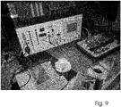
- FIG. 9 is the teaching kit 1 control technology connected to a freely programmable controller 43 via a connecting cable 44, the plug is inserted into the sockets of the digital input / output interface 14a of the teaching 1.
- the connecting lines 45 of the analog plug 18 (see. FIG. 2 ), which carry the analog signals of the height measurement by the ultrasonic sensor 16, inserted into analog input sockets 46 of the controller 43.
- the teaching case 1 with its multiplicity of functions can be controlled by the control 43.
- This also has a touch panel or touch screen 47, which can comfortably complement the button bar or the industrial keypad 22 of the teaching 1.
- control programs for the functionalities of the teaching case 1 can be input or practiced via the touch panel or touch screen 47.
- FIG. 10 are in the front adapter plate shown in the lower edge two equal running Mehrpolbuchsen 48 embedded with corresponding pins of the two Mehrpolbuchsen on the back of the plate are interconnected in parallel.
- the multi-pole socket associated with the interface 14a of the teaching case also has the same design, pin assignment and number of poles.
- first individual sockets 49 are four millimeters in diameter and second single sockets 50 with two millimeters embedded and divided into vertically juxtaposed rows, each with eight sockets.
- the individual sockets 49, 50 serve for insertion of laboratory cable connectors, which can then be accessed on the pins of multi-pin connector.
- a four-millimeter-Einzelbuchse 49 and a two-millimeter-Einzelbuchse 50 are summarized in pairs over a common light-emitting diode, which indicates whether active voltage or data flow prevails. The LED does not light up when the power is off or there is no data flow.
- the two outer left vertical rows with individual sockets 49, 50 as digital inputs, and the two outer right vertical rows with individual sockets 49, 50 are used as digital outputs.
- Individual pins of the multi-pin connector 48 can each be tapped via the individual sockets 49, 50 and fed to a programmable logic controller (PLC) that is incompatible in the terminals.
- PLC programmable logic controller
- the PLC via these single sockets 49, 50 and one of the two multi-pin sockets 48 also control the Lehrkoffer when its interface 14a is connected via a connecting cable to the respective Mehrpolbuchse 48.
- the four-millimeter or two-millimeter individual sockets 49, 50 can be accessed and fed by two different incompatible systems on all pins of the respective multi-pin socket 48.
- the PLC is connection compatible with the Lehrkoffer 1, the use of the in FIG. 10 shown adapter plate not necessary.
Landscapes
- Engineering & Computer Science (AREA)
- Business, Economics & Management (AREA)
- Physics & Mathematics (AREA)
- Educational Administration (AREA)
- Educational Technology (AREA)
- General Physics & Mathematics (AREA)
- Theoretical Computer Science (AREA)
- Sorting Of Articles (AREA)
Priority Applications (1)
| Application Number | Priority Date | Filing Date | Title |
|---|---|---|---|
| EP12155450.5A EP2629280B1 (fr) | 2012-02-14 | 2012-02-14 | Système d'apprentissage pour la vérification et le tri de différentes pièces usinées |
Applications Claiming Priority (1)
| Application Number | Priority Date | Filing Date | Title |
|---|---|---|---|
| EP12155450.5A EP2629280B1 (fr) | 2012-02-14 | 2012-02-14 | Système d'apprentissage pour la vérification et le tri de différentes pièces usinées |
Publications (2)
| Publication Number | Publication Date |
|---|---|
| EP2629280A1 true EP2629280A1 (fr) | 2013-08-21 |
| EP2629280B1 EP2629280B1 (fr) | 2017-02-01 |
Family
ID=45655762
Family Applications (1)
| Application Number | Title | Priority Date | Filing Date |
|---|---|---|---|
| EP12155450.5A Active EP2629280B1 (fr) | 2012-02-14 | 2012-02-14 | Système d'apprentissage pour la vérification et le tri de différentes pièces usinées |
Country Status (1)
| Country | Link |
|---|---|
| EP (1) | EP2629280B1 (fr) |
Cited By (5)
| Publication number | Priority date | Publication date | Assignee | Title |
|---|---|---|---|---|
| CN108514781A (zh) * | 2018-05-24 | 2018-09-11 | 无锡雪浪环境科技股份有限公司 | 脉冲清灰控制器、用该控制器的控制设备及控制方法 |
| CN108806465A (zh) * | 2018-07-26 | 2018-11-13 | 西安工业大学 | 一种模块化plc控制的多模式分拣实训平台 |
| CN109473009A (zh) * | 2018-12-26 | 2019-03-15 | 山东莱茵科技设备有限公司 | 机电一体化传感器实训系统 |
| CN109754695A (zh) * | 2019-03-22 | 2019-05-14 | 北京华航唯实机器人科技股份有限公司 | 一种用于产品检测分拣信息化智能作业的教学设备 |
| CN113270023A (zh) * | 2021-05-12 | 2021-08-17 | 杭州英才规划建筑设计咨询有限公司 | 一种展示效果好的城市规划建设用沙盘 |
Citations (1)
| Publication number | Priority date | Publication date | Assignee | Title |
|---|---|---|---|---|
| DE102007029037A1 (de) | 2007-06-23 | 2008-12-24 | Acksteiner, Fritz, Dr. | Lehrkoffer für Elektrotechnik und Elektronik |
-
2012
- 2012-02-14 EP EP12155450.5A patent/EP2629280B1/fr active Active
Patent Citations (1)
| Publication number | Priority date | Publication date | Assignee | Title |
|---|---|---|---|---|
| DE102007029037A1 (de) | 2007-06-23 | 2008-12-24 | Acksteiner, Fritz, Dr. | Lehrkoffer für Elektrotechnik und Elektronik |
Non-Patent Citations (5)
| Title |
|---|
| BEN ERWIN, MARTHA CYR, CHRIS ROGERS: "LEGO Engineer and RoboLab: Teaching Engineering with LabVIEW from Kindergarten to Graduate School", INTERNATIONAL JOURNAL OF ENGINEERING EDUCATION, vol. 16, no. 3, 2000, pages 181 - 192, XP002680598, Retrieved from the Internet <URL:http://www.ijee.ie/articles/Vol16-3/ijee1121.pdf> [retrieved on 20120723] * |
| KISS G: "Using the Lego-Mindstorm kit in German Computer Science Education", APPLIED MACHINE INTELLIGENCE AND INFORMATICS (SAMI), 2010 IEEE 8TH INTERNATIONAL SYMPOSIUM ON, 28 January 2010 (2010-01-28), IEEE, PISCATAWAY, NJ, USA, pages 101 - 104, XP031644198, ISBN: 978-1-4244-6422-7 * |
| KUO-KAI HSU ET AL: "Build a Home Security Surveillance System Using LEGO MINDSTORMS NXT", INTELLIGENT INFORMATION HIDING AND MULTIMEDIA SIGNAL PROCESSING, 2009. IIH-MSP '09. FIFTH INTERNATIONAL CONFERENCE ON, 12 September 2009 (2009-09-12), IEEE, PISCATAWAY, NJ, USA, pages 254 - 257, XP031569660, ISBN: 978-1-4244-4717-6 * |
| MARKUS WEBER: "Vermittlung von informatischenGrundkonzepten der Realschulbildunganhand einer robotergesteuertenLagerverwaltung", 2008, Friedrich-Alexander Universität Erlangen-Nürnberg, pages i - viii,1-84, XP002680600, Retrieved from the Internet <URL:http://www.robinfun.de/uswa/ha-weber.pdf> [retrieved on 20120723] * |
| TORSTEN K IVERSEN ET AL: "Model-checking real-time control programs: verifying LEGO MINDSTORMSTM systems using UPPAAL", PROCEEDINGS / EUROMICRO RTS 2000 : 12TH EUROMICRO CONFERENCE ON REAL-TIME SYSTEMS, 21 June 2000 (2000-06-21), STOCKHOLM, SWEDEN, pages 147 - 155, XP031665177, ISBN: 978-0-7695-0734-7 * |
Cited By (7)
| Publication number | Priority date | Publication date | Assignee | Title |
|---|---|---|---|---|
| CN108514781A (zh) * | 2018-05-24 | 2018-09-11 | 无锡雪浪环境科技股份有限公司 | 脉冲清灰控制器、用该控制器的控制设备及控制方法 |
| CN108806465A (zh) * | 2018-07-26 | 2018-11-13 | 西安工业大学 | 一种模块化plc控制的多模式分拣实训平台 |
| CN109473009A (zh) * | 2018-12-26 | 2019-03-15 | 山东莱茵科技设备有限公司 | 机电一体化传感器实训系统 |
| CN109754695A (zh) * | 2019-03-22 | 2019-05-14 | 北京华航唯实机器人科技股份有限公司 | 一种用于产品检测分拣信息化智能作业的教学设备 |
| CN109754695B (zh) * | 2019-03-22 | 2024-03-12 | 北京华航唯实机器人科技股份有限公司 | 一种用于产品检测分拣信息化智能作业的教学设备 |
| CN113270023A (zh) * | 2021-05-12 | 2021-08-17 | 杭州英才规划建筑设计咨询有限公司 | 一种展示效果好的城市规划建设用沙盘 |
| CN113270023B (zh) * | 2021-05-12 | 2022-10-21 | 杭州英才规划建筑设计咨询有限公司 | 一种展示效果好的城市规划建设用沙盘 |
Also Published As
| Publication number | Publication date |
|---|---|
| EP2629280B1 (fr) | 2017-02-01 |
Similar Documents
| Publication | Publication Date | Title |
|---|---|---|
| DE10107208B4 (de) | System für das Kommunizieren mit Hochfrequenz-Etiketten | |
| EP2629280B1 (fr) | Système d'apprentissage pour la vérification et le tri de différentes pièces usinées | |
| DE3713155A1 (de) | Einrichtung zum automatischen programmierten pruefen von prueflingen aller art | |
| DD152870A1 (de) | Verfahren und vorrichtung zum klassieren in bewegung befindlichen stueckgutes | |
| EP1078138A1 (fr) | Transpondeur mobile pour vehicule | |
| EP2693218A1 (fr) | Procédé et dispositif pour determiner un arrangement d'articles de laboratoire sur un établi d'un station de travail laboratoire | |
| WO2012146772A1 (fr) | Dispositif de poinçonnage pourvu d'une plaque de réception éclairée | |
| EP3012603B1 (fr) | Procede et programme informatique destines a la detection et la quantification de grandeurs dans un processus de production | |
| DE4134225C2 (de) | Vorrichtung zum Erfassen, Speichern und Übertragen von Daten jeglicher Art | |
| DE102018113989A1 (de) | Fertigungsvorrichtung und verfahren | |
| WO1998043752A1 (fr) | Procede et dispositif pour detecter des pieces mal orientees et/ou s'ecartant d'un modele donne | |
| DE102017223501A1 (de) | Verfahren und Vorrichtung zur Detektion von Defekten in elektrischen Komponenten oder Baugruppen | |
| EP2851684B1 (fr) | Procédé et dispositif d'identification de fractions dans un collecteur de fraction d'un chromatographe en phase liquide | |
| DE4410781A1 (de) | Einrichtung zum Identifizieren von Proben in einem automatischen Meßsystem | |
| DE19844797C2 (de) | Fertigungs- und/oder Montagevorrichtung | |
| EP0494617A2 (fr) | Dispositif d'identification sans contact d'objects | |
| DE112007001096T5 (de) | Auto-Einlern-System | |
| DE102014117104A1 (de) | Verfahren zur Kalibrierung einer Robotik relativ zu einem Lagermagazin | |
| DE102018002627A1 (de) | Vorrichtung zur Aufnahme des außeren Zustands eines Objekts | |
| DE102006016562A1 (de) | Regal | |
| DE202018101018U1 (de) | Bauteil-Belegungserkennungsvorrichtung eines Werkstückträgers | |
| EP2199765A1 (fr) | Procédé et appareil de mesure de couleur manuelle destinés à la mesure d'une échelle de mesure de couleur | |
| DE3804499A1 (de) | Verfahren zum sortieren von kaesten fuer getraenkeflaschen sowie kasten zur verwendung bei diesem verfahren und vorrichtung zur durchfuehrung des verfahrens | |
| DE102016117472A1 (de) | Testvorrichtung zum Überprüfen einer Bestückfunktion eines Bestückautomaten, System aus einem Bestückautomat und einer Testvorrichtung sowie Verfahren zum Überprüfen einer Bestückfunktion eines Bestückautomaten | |
| DE112020005314T5 (de) | Näherungssensor mit integrierten Steuermerkmalen und Verfahren zu dessen Betrieb |
Legal Events
| Date | Code | Title | Description |
|---|---|---|---|
| PUAI | Public reference made under article 153(3) epc to a published international application that has entered the european phase |
Free format text: ORIGINAL CODE: 0009012 |
|
| AK | Designated contracting states |
Kind code of ref document: A1 Designated state(s): AL AT BE BG CH CY CZ DE DK EE ES FI FR GB GR HR HU IE IS IT LI LT LU LV MC MK MT NL NO PL PT RO RS SE SI SK SM TR |
|
| AX | Request for extension of the european patent |
Extension state: BA ME |
|
| RIN1 | Information on inventor provided before grant (corrected) |
Inventor name: BUETTNER, LEONHARD |
|
| RIN1 | Information on inventor provided before grant (corrected) |
Inventor name: BUETTNER, LEONHARD |
|
| 17P | Request for examination filed |
Effective date: 20140210 |
|
| RBV | Designated contracting states (corrected) |
Designated state(s): AL AT BE BG CH CY CZ DE DK EE ES FI FR GB GR HR HU IE IS IT LI LT LU LV MC MK MT NL NO PL PT RO RS SE SI SK SM TR |
|
| 17Q | First examination report despatched |
Effective date: 20140716 |
|
| GRAP | Despatch of communication of intention to grant a patent |
Free format text: ORIGINAL CODE: EPIDOSNIGR1 |
|
| INTG | Intention to grant announced |
Effective date: 20160303 |
|
| GRAJ | Information related to disapproval of communication of intention to grant by the applicant or resumption of examination proceedings by the epo deleted |
Free format text: ORIGINAL CODE: EPIDOSDIGR1 |
|
| GRAP | Despatch of communication of intention to grant a patent |
Free format text: ORIGINAL CODE: EPIDOSNIGR1 |
|
| INTG | Intention to grant announced |
Effective date: 20160809 |
|
| GRAS | Grant fee paid |
Free format text: ORIGINAL CODE: EPIDOSNIGR3 |
|
| GRAA | (expected) grant |
Free format text: ORIGINAL CODE: 0009210 |
|
| AK | Designated contracting states |
Kind code of ref document: B1 Designated state(s): AL AT BE BG CH CY CZ DE DK EE ES FI FR GB GR HR HU IE IS IT LI LT LU LV MC MK MT NL NO PL PT RO RS SE SI SK SM TR |
|
| REG | Reference to a national code |
Ref country code: GB Ref legal event code: FG4D Free format text: NOT ENGLISH |
|
| REG | Reference to a national code |
Ref country code: CH Ref legal event code: EP Ref country code: AT Ref legal event code: REF Ref document number: 866123 Country of ref document: AT Kind code of ref document: T Effective date: 20170215 |
|
| REG | Reference to a national code |
Ref country code: IE Ref legal event code: FG4D Free format text: LANGUAGE OF EP DOCUMENT: GERMAN |
|
| REG | Reference to a national code |
Ref country code: DE Ref legal event code: R096 Ref document number: 502012009406 Country of ref document: DE |
|
| REG | Reference to a national code |
Ref country code: NL Ref legal event code: MP Effective date: 20170201 |
|
| REG | Reference to a national code |
Ref country code: LT Ref legal event code: MG4D |
|
| REG | Reference to a national code |
Ref country code: FR Ref legal event code: PLFP Year of fee payment: 6 |
|
| PG25 | Lapsed in a contracting state [announced via postgrant information from national office to epo] |
Ref country code: FI Free format text: LAPSE BECAUSE OF FAILURE TO SUBMIT A TRANSLATION OF THE DESCRIPTION OR TO PAY THE FEE WITHIN THE PRESCRIBED TIME-LIMIT Effective date: 20170201 Ref country code: IS Free format text: LAPSE BECAUSE OF FAILURE TO SUBMIT A TRANSLATION OF THE DESCRIPTION OR TO PAY THE FEE WITHIN THE PRESCRIBED TIME-LIMIT Effective date: 20170601 Ref country code: HR Free format text: LAPSE BECAUSE OF FAILURE TO SUBMIT A TRANSLATION OF THE DESCRIPTION OR TO PAY THE FEE WITHIN THE PRESCRIBED TIME-LIMIT Effective date: 20170201 Ref country code: GR Free format text: LAPSE BECAUSE OF FAILURE TO SUBMIT A TRANSLATION OF THE DESCRIPTION OR TO PAY THE FEE WITHIN THE PRESCRIBED TIME-LIMIT Effective date: 20170502 Ref country code: LT Free format text: LAPSE BECAUSE OF FAILURE TO SUBMIT A TRANSLATION OF THE DESCRIPTION OR TO PAY THE FEE WITHIN THE PRESCRIBED TIME-LIMIT Effective date: 20170201 Ref country code: NO Free format text: LAPSE BECAUSE OF FAILURE TO SUBMIT A TRANSLATION OF THE DESCRIPTION OR TO PAY THE FEE WITHIN THE PRESCRIBED TIME-LIMIT Effective date: 20170501 |
|
| PG25 | Lapsed in a contracting state [announced via postgrant information from national office to epo] |
Ref country code: ES Free format text: LAPSE BECAUSE OF FAILURE TO SUBMIT A TRANSLATION OF THE DESCRIPTION OR TO PAY THE FEE WITHIN THE PRESCRIBED TIME-LIMIT Effective date: 20170201 Ref country code: BG Free format text: LAPSE BECAUSE OF FAILURE TO SUBMIT A TRANSLATION OF THE DESCRIPTION OR TO PAY THE FEE WITHIN THE PRESCRIBED TIME-LIMIT Effective date: 20170501 Ref country code: NL Free format text: LAPSE BECAUSE OF FAILURE TO SUBMIT A TRANSLATION OF THE DESCRIPTION OR TO PAY THE FEE WITHIN THE PRESCRIBED TIME-LIMIT Effective date: 20170201 Ref country code: SE Free format text: LAPSE BECAUSE OF FAILURE TO SUBMIT A TRANSLATION OF THE DESCRIPTION OR TO PAY THE FEE WITHIN THE PRESCRIBED TIME-LIMIT Effective date: 20170201 Ref country code: LV Free format text: LAPSE BECAUSE OF FAILURE TO SUBMIT A TRANSLATION OF THE DESCRIPTION OR TO PAY THE FEE WITHIN THE PRESCRIBED TIME-LIMIT Effective date: 20170201 Ref country code: PL Free format text: LAPSE BECAUSE OF FAILURE TO SUBMIT A TRANSLATION OF THE DESCRIPTION OR TO PAY THE FEE WITHIN THE PRESCRIBED TIME-LIMIT Effective date: 20170201 Ref country code: PT Free format text: LAPSE BECAUSE OF FAILURE TO SUBMIT A TRANSLATION OF THE DESCRIPTION OR TO PAY THE FEE WITHIN THE PRESCRIBED TIME-LIMIT Effective date: 20170601 Ref country code: RS Free format text: LAPSE BECAUSE OF FAILURE TO SUBMIT A TRANSLATION OF THE DESCRIPTION OR TO PAY THE FEE WITHIN THE PRESCRIBED TIME-LIMIT Effective date: 20170201 |
|
| REG | Reference to a national code |
Ref country code: CH Ref legal event code: PL |
|
| PG25 | Lapsed in a contracting state [announced via postgrant information from national office to epo] |
Ref country code: CZ Free format text: LAPSE BECAUSE OF FAILURE TO SUBMIT A TRANSLATION OF THE DESCRIPTION OR TO PAY THE FEE WITHIN THE PRESCRIBED TIME-LIMIT Effective date: 20170201 Ref country code: SK Free format text: LAPSE BECAUSE OF FAILURE TO SUBMIT A TRANSLATION OF THE DESCRIPTION OR TO PAY THE FEE WITHIN THE PRESCRIBED TIME-LIMIT Effective date: 20170201 Ref country code: LI Free format text: LAPSE BECAUSE OF NON-PAYMENT OF DUE FEES Effective date: 20170228 Ref country code: CH Free format text: LAPSE BECAUSE OF NON-PAYMENT OF DUE FEES Effective date: 20170228 Ref country code: EE Free format text: LAPSE BECAUSE OF FAILURE TO SUBMIT A TRANSLATION OF THE DESCRIPTION OR TO PAY THE FEE WITHIN THE PRESCRIBED TIME-LIMIT Effective date: 20170201 Ref country code: RO Free format text: LAPSE BECAUSE OF FAILURE TO SUBMIT A TRANSLATION OF THE DESCRIPTION OR TO PAY THE FEE WITHIN THE PRESCRIBED TIME-LIMIT Effective date: 20170201 Ref country code: IT Free format text: LAPSE BECAUSE OF FAILURE TO SUBMIT A TRANSLATION OF THE DESCRIPTION OR TO PAY THE FEE WITHIN THE PRESCRIBED TIME-LIMIT Effective date: 20170201 |
|
| REG | Reference to a national code |
Ref country code: DE Ref legal event code: R097 Ref document number: 502012009406 Country of ref document: DE |
|
| REG | Reference to a national code |
Ref country code: IE Ref legal event code: MM4A |
|
| PG25 | Lapsed in a contracting state [announced via postgrant information from national office to epo] |
Ref country code: MC Free format text: LAPSE BECAUSE OF FAILURE TO SUBMIT A TRANSLATION OF THE DESCRIPTION OR TO PAY THE FEE WITHIN THE PRESCRIBED TIME-LIMIT Effective date: 20170201 Ref country code: SM Free format text: LAPSE BECAUSE OF FAILURE TO SUBMIT A TRANSLATION OF THE DESCRIPTION OR TO PAY THE FEE WITHIN THE PRESCRIBED TIME-LIMIT Effective date: 20170201 Ref country code: DK Free format text: LAPSE BECAUSE OF FAILURE TO SUBMIT A TRANSLATION OF THE DESCRIPTION OR TO PAY THE FEE WITHIN THE PRESCRIBED TIME-LIMIT Effective date: 20170201 |
|
| PLBE | No opposition filed within time limit |
Free format text: ORIGINAL CODE: 0009261 |
|
| STAA | Information on the status of an ep patent application or granted ep patent |
Free format text: STATUS: NO OPPOSITION FILED WITHIN TIME LIMIT |
|
| PG25 | Lapsed in a contracting state [announced via postgrant information from national office to epo] |
Ref country code: LU Free format text: LAPSE BECAUSE OF NON-PAYMENT OF DUE FEES Effective date: 20170214 |
|
| 26N | No opposition filed |
Effective date: 20171103 |
|
| REG | Reference to a national code |
Ref country code: FR Ref legal event code: PLFP Year of fee payment: 7 |
|
| REG | Reference to a national code |
Ref country code: BE Ref legal event code: MM Effective date: 20170228 |
|
| PG25 | Lapsed in a contracting state [announced via postgrant information from national office to epo] |
Ref country code: SI Free format text: LAPSE BECAUSE OF FAILURE TO SUBMIT A TRANSLATION OF THE DESCRIPTION OR TO PAY THE FEE WITHIN THE PRESCRIBED TIME-LIMIT Effective date: 20170201 Ref country code: IE Free format text: LAPSE BECAUSE OF NON-PAYMENT OF DUE FEES Effective date: 20170214 |
|
| PG25 | Lapsed in a contracting state [announced via postgrant information from national office to epo] |
Ref country code: BE Free format text: LAPSE BECAUSE OF NON-PAYMENT OF DUE FEES Effective date: 20170228 |
|
| PGFP | Annual fee paid to national office [announced via postgrant information from national office to epo] |
Ref country code: FR Payment date: 20180213 Year of fee payment: 7 |
|
| PG25 | Lapsed in a contracting state [announced via postgrant information from national office to epo] |
Ref country code: MT Free format text: LAPSE BECAUSE OF FAILURE TO SUBMIT A TRANSLATION OF THE DESCRIPTION OR TO PAY THE FEE WITHIN THE PRESCRIBED TIME-LIMIT Effective date: 20170201 |
|
| PG25 | Lapsed in a contracting state [announced via postgrant information from national office to epo] |
Ref country code: HU Free format text: LAPSE BECAUSE OF FAILURE TO SUBMIT A TRANSLATION OF THE DESCRIPTION OR TO PAY THE FEE WITHIN THE PRESCRIBED TIME-LIMIT; INVALID AB INITIO Effective date: 20120214 |
|
| PG25 | Lapsed in a contracting state [announced via postgrant information from national office to epo] |
Ref country code: CY Free format text: LAPSE BECAUSE OF NON-PAYMENT OF DUE FEES Effective date: 20170201 |
|
| PG25 | Lapsed in a contracting state [announced via postgrant information from national office to epo] |
Ref country code: MK Free format text: LAPSE BECAUSE OF FAILURE TO SUBMIT A TRANSLATION OF THE DESCRIPTION OR TO PAY THE FEE WITHIN THE PRESCRIBED TIME-LIMIT Effective date: 20170201 |
|
| PG25 | Lapsed in a contracting state [announced via postgrant information from national office to epo] |
Ref country code: FR Free format text: LAPSE BECAUSE OF NON-PAYMENT OF DUE FEES Effective date: 20190228 |
|
| PG25 | Lapsed in a contracting state [announced via postgrant information from national office to epo] |
Ref country code: TR Free format text: LAPSE BECAUSE OF FAILURE TO SUBMIT A TRANSLATION OF THE DESCRIPTION OR TO PAY THE FEE WITHIN THE PRESCRIBED TIME-LIMIT Effective date: 20170201 |
|
| PG25 | Lapsed in a contracting state [announced via postgrant information from national office to epo] |
Ref country code: AL Free format text: LAPSE BECAUSE OF FAILURE TO SUBMIT A TRANSLATION OF THE DESCRIPTION OR TO PAY THE FEE WITHIN THE PRESCRIBED TIME-LIMIT Effective date: 20170201 |
|
| PGFP | Annual fee paid to national office [announced via postgrant information from national office to epo] |
Ref country code: AT Payment date: 20210216 Year of fee payment: 10 |
|
| PGFP | Annual fee paid to national office [announced via postgrant information from national office to epo] |
Ref country code: GB Payment date: 20220330 Year of fee payment: 11 |
|
| REG | Reference to a national code |
Ref country code: DE Ref legal event code: R119 Ref document number: 502012009406 Country of ref document: DE |
|
| REG | Reference to a national code |
Ref country code: AT Ref legal event code: MM01 Ref document number: 866123 Country of ref document: AT Kind code of ref document: T Effective date: 20220214 |
|
| PG25 | Lapsed in a contracting state [announced via postgrant information from national office to epo] |
Ref country code: AT Free format text: LAPSE BECAUSE OF NON-PAYMENT OF DUE FEES Effective date: 20220214 |
|
| REG | Reference to a national code |
Ref country code: DE Ref legal event code: R073 Ref document number: 502012009406 Country of ref document: DE |
|
| REG | Reference to a national code |
Ref country code: DE Ref legal event code: R074 Ref document number: 502012009406 Country of ref document: DE |
|
| PG25 | Lapsed in a contracting state [announced via postgrant information from national office to epo] |
Ref country code: DE Free format text: LAPSE BECAUSE OF NON-PAYMENT OF DUE FEES Effective date: 20220901 |
|
| PG25 | Lapsed in a contracting state [announced via postgrant information from national office to epo] |
Ref country code: DE Free format text: LAPSE BECAUSE OF NON-PAYMENT OF DUE FEES Effective date: 20220901 |
|
| PGRI | Patent reinstated in contracting state [announced from national office to epo] |
Ref country code: DE Effective date: 20230129 |
|
| GBPC | Gb: european patent ceased through non-payment of renewal fee |
Effective date: 20230214 |
|
| PG25 | Lapsed in a contracting state [announced via postgrant information from national office to epo] |
Ref country code: GB Free format text: LAPSE BECAUSE OF NON-PAYMENT OF DUE FEES Effective date: 20230214 |
|
| PG25 | Lapsed in a contracting state [announced via postgrant information from national office to epo] |
Ref country code: GB Free format text: LAPSE BECAUSE OF NON-PAYMENT OF DUE FEES Effective date: 20230214 |
|
| PGFP | Annual fee paid to national office [announced via postgrant information from national office to epo] |
Ref country code: DE Payment date: 20250417 Year of fee payment: 14 |