EP2629548A2 - Dispositif de détection et de transmission de données de mesure - Google Patents
Dispositif de détection et de transmission de données de mesure Download PDFInfo
- Publication number
- EP2629548A2 EP2629548A2 EP13450003.2A EP13450003A EP2629548A2 EP 2629548 A2 EP2629548 A2 EP 2629548A2 EP 13450003 A EP13450003 A EP 13450003A EP 2629548 A2 EP2629548 A2 EP 2629548A2
- Authority
- EP
- European Patent Office
- Prior art keywords
- coupling electrode
- measurement data
- acquisition unit
- data acquisition
- conduit
- Prior art date
- Legal status (The legal status is an assumption and is not a legal conclusion. Google has not performed a legal analysis and makes no representation as to the accuracy of the status listed.)
- Withdrawn
Links
- 238000005259 measurement Methods 0.000 title claims abstract description 87
- 238000004891 communication Methods 0.000 title description 4
- 230000008878 coupling Effects 0.000 claims abstract description 136
- 238000010168 coupling process Methods 0.000 claims abstract description 136
- 238000005859 coupling reaction Methods 0.000 claims abstract description 136
- 230000005540 biological transmission Effects 0.000 claims abstract description 93
- 238000012546 transfer Methods 0.000 claims description 9
- 230000001939 inductive effect Effects 0.000 claims description 4
- 239000011248 coating agent Substances 0.000 claims description 3
- 238000000576 coating method Methods 0.000 claims description 3
- XUIMIQQOPSSXEZ-UHFFFAOYSA-N Silicon Chemical compound [Si] XUIMIQQOPSSXEZ-UHFFFAOYSA-N 0.000 claims description 2
- 230000004907 flux Effects 0.000 claims description 2
- 229910052710 silicon Inorganic materials 0.000 claims description 2
- 239000010703 silicon Substances 0.000 claims description 2
- 238000012549 training Methods 0.000 description 4
- 238000010586 diagram Methods 0.000 description 3
- 230000006870 function Effects 0.000 description 3
- 230000008901 benefit Effects 0.000 description 2
- 230000002457 bidirectional effect Effects 0.000 description 2
- 238000013461 design Methods 0.000 description 2
- 238000011161 development Methods 0.000 description 2
- 238000009434 installation Methods 0.000 description 2
- 238000000034 method Methods 0.000 description 2
- 230000008569 process Effects 0.000 description 2
- 238000012545 processing Methods 0.000 description 2
- RYGMFSIKBFXOCR-UHFFFAOYSA-N Copper Chemical compound [Cu] RYGMFSIKBFXOCR-UHFFFAOYSA-N 0.000 description 1
- LFQSCWFLJHTTHZ-UHFFFAOYSA-N Ethanol Chemical compound CCO LFQSCWFLJHTTHZ-UHFFFAOYSA-N 0.000 description 1
- 238000013459 approach Methods 0.000 description 1
- 239000003990 capacitor Substances 0.000 description 1
- 229910052802 copper Inorganic materials 0.000 description 1
- 239000010949 copper Substances 0.000 description 1
- 239000000428 dust Substances 0.000 description 1
- 235000013312 flour Nutrition 0.000 description 1
- -1 gravel) Substances 0.000 description 1
- 239000007788 liquid Substances 0.000 description 1
- 230000004807 localization Effects 0.000 description 1
- 238000004519 manufacturing process Methods 0.000 description 1
- 230000001404 mediated effect Effects 0.000 description 1
- 230000003287 optical effect Effects 0.000 description 1
- 238000009420 retrofitting Methods 0.000 description 1
- 239000007787 solid Substances 0.000 description 1
Images

Classifications
-
- H—ELECTRICITY
- H04—ELECTRIC COMMUNICATION TECHNIQUE
- H04Q—SELECTING
- H04Q9/00—Arrangements in telecontrol or telemetry systems for selectively calling a substation from a main station, in which substation desired apparatus is selected for applying a control signal thereto or for obtaining measured values therefrom
-
- H—ELECTRICITY
- H04—ELECTRIC COMMUNICATION TECHNIQUE
- H04B—TRANSMISSION
- H04B5/00—Near-field transmission systems, e.g. inductive or capacitive transmission systems
- H04B5/20—Near-field transmission systems, e.g. inductive or capacitive transmission systems characterised by the transmission technique; characterised by the transmission medium
- H04B5/22—Capacitive coupling
-
- H—ELECTRICITY
- H04—ELECTRIC COMMUNICATION TECHNIQUE
- H04Q—SELECTING
- H04Q2209/00—Arrangements in telecontrol or telemetry systems
- H04Q2209/40—Arrangements in telecontrol or telemetry systems using a wireless architecture
- H04Q2209/47—Arrangements in telecontrol or telemetry systems using a wireless architecture using RFID associated with sensors
Definitions
- the invention relates to a device for recording and transmitting measurement data comprising a measurement data acquisition unit with a data transmission module for transmitting measurement data to a reading device.
- the invention further relates to a system for acquiring and transmitting measurement data comprising a measurement data acquisition unit and a read and / or write unit.
- the term data acquisition refers to the recording of analog signals by means of suitable hardware.
- digital measurement data are generated with the aid of an analog-to-digital converter, which are then read out immediately by means of a suitable reading device or stored in a memory of the measurement data acquisition unit for later read-out.
- some measurement data acquisition units also support the possibility of bidirectional data transmission, in which additionally data is written by a read and / or write unit into the measurement data acquisition unit, e.g. for programming purposes or to realize more complex data transmission protocols. More complex data transmission protocols may, for example, enable cryptographic functions, in particular encrypted data transmission and / or mutual authentication.
- the present invention relates in particular to measurement data acquisition units which are installed at the location of the measurement data acquisition.
- Such data acquisition units can be located in hard to reach places, so that the manual readout of the measured data is difficult. Therefore, systems for wireless data transmission between the measured data acquisition unit and the reading and / or writing unit have already become known.
- a disadvantage of the conventional wireless data transmission systems is that the confidentiality and tamper resistance of the data is not always guaranteed.
- the invention is therefore based on the object to improve the data transmission between a measurement data acquisition unit and an associated read and / or write unit to the extent that the confidentiality and tamper resistance of the data is guaranteed.
- the invention essentially provides in a device and in a system of the type initially mentioned that the data transmission module is designed as a capacitive data transmission module having at least one coupling electrode, so that the data transmission via a capacitive coupling between the measured data acquisition unit and the read and / or write unit can be done.
- the capacitive data transmission has the advantage that the transmission only works over relatively small distances, so that it is necessary for the transmission of data to approximate the read and / or write unit to the measurement data acquisition unit or the measurement data acquisition unit or a conductively connected thereto with the component Even to touch reading and / or writing unit. Due to the limited range, the risk of interception or manipulation of the measurement data during transmission by unauthorized persons is reduced.
- the data transmission module of the measurement data acquisition unit and the read and / or write unit each have a coupling electrode with an associated coupling capacitance for a capacitive signal output. or coupling on.
- the coupling electrode is formed as a conductive surface, in particular a copper surface or metallic surface.
- Both components, ie the measurement data acquisition unit and the read and / or write unit are preferably each grounded.
- the circuit can be closed. Alternatively or additionally, the circuit can be closed by a direct capacitive coupling between the ground electrodes.
- the capacitive data transmission preferably functions so that the data transmission module of the measurement data acquisition unit has means for generating a capacitive near field through which the measurement data are transmitted, such that when the measurement data acquisition unit is touched or when approaching the measurement data acquisition unit by the read and / or write unit, an AC circuit closes and an electrical flux is generated, which can be detected by the data transmission module of the reading and / or writing unit.
- a disadvantage of the capacitive data transmission here is that no standardized components for use in data transmission modules of measurement data acquisition systems are available with which the capacitive data transmission can be implemented in a simple and cost-effective manner. This can be explained in particular by the fact that the use of capacitive data transmission systems has so far been made commercially available only to a very limited extent So far, the development of mass-production models of data transfer modules has not been worthwhile.
- the invention preferably provides for the capacitive data transmission module of the measurement data acquisition unit and / or the read and / or write unit to comprise an RFID data transfer microchip or a radio reception microchip designed for inductive data transmission, at the antenna connection of which the at least one coupling electrode connected.
- microchips which were not designed for use in capacitive data transmission are suitable for use as a receiving and / or transmitting module in the capacitive data transmission module of a measured data acquisition system. It is of particular advantage that the used reaching RFID microchips and broadcast receiving chips in very large quantities at very low cost are generally available. The miniaturization of the data transmission module achieved with these microchips also allows the installation of small-scale measurement data acquisition units, in which case retrofitting of existing data acquisition units is also readily possible.
- the capacitive data transmission acts at least one coupling electrode or a coupling capacitance as an "antenna".
- P refers the at least one coupling electrode or a coupling capacitor is connected to the terminals of the RFID microchip provided for the receiving or transmitting coil or to the connections of the radio-receiving microchip provided for the dipole antenna. In certain cases, it may be necessary for the coupling electrode to be connected to the microchip via an impedance matching matching network.
- the RFID microchips used are those designed as read-write interfaces for inductive data transmission. Such RFID microchips are used by millions in reading devices for RFID transponders in applications for the automatic identification and localization of objects. It is preferably provided that the RFID data transmission microchip is designed for data transmission in accordance with ISO / IEC 14443 or ISO / IEC 15693.
- RFID microchips have different operating modes, namely peer-to-peer mode (ISO 18092), reader / writer mode (ISO 14443) and card emulation mode. Most commonly used is Reader / Writer mode, which enables communication with passive RFID transponders. Passive RFID transponders are distinguished by the fact that they do not have their own power supply, but that they only receive the energy required for communication and processing of internal processes from the field of the read / write unit. In peer-to-peer mode, however, both the transmitter and the receiver can actively communicate (ISO 18092, active mode). In the context of the invention, it is preferred that a peer-to-peer mode of the RFID data transfer microchip is set.
- the transmission of the data can take place both contactless and contact-based.
- the signals to be transmitted are preferably modulated onto a carrier signal, and in the data transmission module of the read and / or write unit, the signals are demodulated again.
- the described process may be provided in an equivalent manner for the data transmission from the reading and / or writing unit to the measurement data acquisition unit.
- the modulation of the carrier signal can basically be done in any way.
- the RFID data transfer microchip comprises an amplitude modulator / demodulator or an amplitude shift keying.
- the RFID data transmission microchip is designed for data transmission in the ISM frequency bands, in particular in the frequency bands of 13.553 to 13.567 MHz, but also 6.765 - 6.795 MHz or 26.957 - 27.283 MHz.
- a preferred example of RFID microchips which have been tried and tested and are available at low cost, is the PN512 chip from NXP B.V. or TRF7970A from Texas Instruments.
- the preferably provided broadcast receiving chips are, for example, microchips, as used in mobile telephones or miniature radios. In this case, it can be provided, for example, that the broadcast receiving chip is designed for reception via ultra-short wave or short-wave.
- a radio reception chip of the type Si4734 from Silicon Labs has proven to be particularly suitable.
- the broadcast receiving chip comprises an AM demodulator for the shortwave range.
- the coupling electrode of the data transmission module used for the capacitive data transmission can be arranged on an outer surface of a housing of the measurement data acquisition unit or the read and / or write unit.
- the coupling electrode is formed as a conductive coating.
- the measurement data acquisition unit has a sensor with which the analog variable to be measured is detected.
- the sensor may be configured to detect flow rate, amount of heat, temperature, solution concentration (e.g., sugar level, alcohol level, acidity) or pressure.
- a measurement data acquisition unit is used which comprises fastening means for fastening the measurement data acquisition unit to an electrically conductive conduit. This makes it possible to arrange the sensor so that it protrudes into the tube interior or is in communication with the tube interior, the sensor e.g. flows around the medium to be measured.
- the media to be measured may be solid (e.g., gravel), dust (e.g., flour with air), liquid, and / or gaseous.
- the attachment of the measured data acquisition unit to a conduit allows a simple embodiment of the capacitive coupling, in which the data transmission module has at least one further coupling electrode which is electrically connected to the conduit in the state attached to the conduit of the measurement data acquisition unit.
- the data transmission can be carried out with the concomitant use of the electrically conductive conduit.
- a particularly good coupling results here, if, as corresponds to a preferred development, the measurement data acquisition unit and the read and / or write unit at a distance from each other on a pipe or on two different, electrically or by means of capacitive coupling connected pipes are attached.
- the possibility of using the electrically conductive conduit, on which the measurement data acquisition unit is arranged, in the context of the capacitive coupling results in a number of advantageous embodiments.
- the measurement data acquisition unit is attached to a conduit, wherein a first coupling electrode of the measurement data acquisition unit disposed on the housing and a second coupling electrode is electrically connected to the conduit, and that the reading and / or writing unit has a third and a fourth Coupling electrode, wherein for data transmission, a capacitive coupling path between the first and the third coupling electrode and an electrical connection or a capacitive coupling path between the fourth coupling electrode and the conduit are provided.
- the measurement data acquisition unit is attached to a conduit, wherein a first coupling electrode of the measurement data acquisition unit disposed on the housing and a second coupling electrode is electrically connected to the conduit, and that the reading and / or writing unit is attached to the conduit wherein a third coupling electrode of the read and / or write unit on the housing and a fourth coupling electrode is electrically connected to the conduit, wherein for data transmission, a capacitive coupling path between the first and the third coupling electrode and an over the conduit leading electrical connection between the second and the fourth coupling electrode are provided.
- the measurement data acquisition unit is attached to a first conduit, wherein a first coupling electrode of the measurement data acquisition unit arranged on the housing and a second coupling electrode is electrically connected to the first conduit, and that the read and / or write unit at a second Conduit is attached, wherein a third coupling electrode of the read and / or write unit disposed on the housing and a fourth coupling electrode is electrically connected to the second conduit, wherein for data transmission, a capacitive coupling path between the first and the third coupling electrode and a capacitive coupling path between the first and the second conduit are provided.
- the measurement data acquisition unit is attached to a preferably non-conductive conduit, wherein a first coupling electrode and a second coupling electrode of the measurement data acquisition unit are arranged on the housing, and that the reading and / or writing unit on its housing a third and a Fourth coupling electrode, wherein the coupling electrodes are arranged so that the first and the third coupling electrode and the second and the fourth coupling electrode in a read or write position of the read and / or write unit are arranged opposite each other, wherein for data transmission, a capacitive coupling path between the first and the third coupling electrode and a capacitive coupling path between the second and the fourth coupling electrode are provided.
- the measurement data acquisition unit can have an optical display on which, for example, measurement data or status information can be displayed.
- the reading and / or writing unit may be lance-shaped, so that the user can more easily approach the data acquisition unit.
- the lance tip is advantageously equipped with a coupling electrode.
- both the measurement data acquisition unit and the read and / or write unit can transmit and receive data, so that bidirectional data transmission takes place.
- the reading and / or writing unit or the measuring data acquisition unit can be equipped with an energy converter which is able to convert different types of energy into electrical energy which is used for the energy supply of the measuring data acquisition unit or the reading and / or writing unit can be used.
- an energy converter which is able to convert different types of energy into electrical energy which is used for the energy supply of the measuring data acquisition unit or the reading and / or writing unit can be used.
- mechanical vibrations, temperature differences, ambient light, etc. can be converted into electrical energy.
- the read and / or write unit may have an interface for data transfer.
- This interface may e.g. be designed as LAN, Wlan or 6LoWPAN interface or as an interface for a measurement, installation, and building bus system.
- the measurement data may, in a further preferred embodiment, be stored in electronic data processing systems and e.g. be queried via a limited access from the Internet.
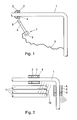
- FIG. 1 A first embodiment of the data transmission system according to the invention
- Fig. 2 a second embodiment the data transmission system according to the invention
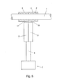
- Fig. 3 a reading and / or writing device designed as a lance
- Fig. 4 A third embodiment of the data transmission system according to the invention
- Fig. 5 A fourth embodiment of the data transmission system according to the invention
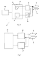
- Fig. 6 a simplified circuit diagram of a data transmission module with an RFID interface chip and two coupling electrodes
- Fig. 7 a simplified circuit diagram of a data transmission module with a broadcast receiving chip and two coupling electrodes.
- a conduit 1 is shown, which is traversed by a medium.
- a measuring data acquisition unit 2 of annular design is provided on the conduit 1 .
- the measurement data acquisition unit 2 is arranged so as to surround the conduit 1 and contact the conduit 1 with its inner surface.
- the measurement data acquisition unit 2 includes a sensor capable of measuring a physical quantity of the medium flowing in the conduit 1, such as a temperature or the like.
- the measurement data acquisition unit 2 has at least one first electrode 3 on its outer circumference and at least one second electrode 4 on its inner circumference.
- the second electrode 4 is conductively connected to the electrically conductive conduit 1.
- the first electrode 3 and the second electrode 4 are preferably each made cylindrical.
- the reading and / or writing unit 5 denotes a read and / or write unit which serves for reading out the measurement data provided by the measurement data acquisition unit 2.
- the reading and / or writing unit 5 has a lance shape and has a first end with a third electrode 6. At the opposite end, the reading and / or writing unit 5 has a grip part 7, the outside of which carries a fourth electrode 8. in the Handle 7 is the required for reading or writing electronics including the data transmission module integrated.
- the lance-shaped reading and / or writing unit 5 with the third electrode 6 is brought to the first electrode 3 formed on the measuring data acquisition unit 2.
- the third electrode 6 may contact the first electrode 3 in this case.
- a capacitive coupling path is formed, wherein the signal conclusion takes place via a coupling of the second electrode 4 with the fourth electrode 8.
- the fourth electrode 8 may be electrically connected to the conduit 1 by means of an electrically conductive connection 9.
- a capacitive coupling path can be formed between the fourth electrode 8 and the electrically conductive conduit 1.
- the measurement data acquisition unit is again denoted by 2 and the read and / or write unit by 5. Both units 2, 5 are annular in cross-section and attached to the conduit 1.
- the conduit 1 is again formed electrically conductive.
- the measurement data acquisition unit 2 has a first electrode 3 on its outer surface and a second electrode 4 on its inner surface.
- the reading and / or writing unit 5 has a third electrode 6 on its outer surface and a fourth electrode 8 on its inner surface.
- the data transmission between the measured data acquisition unit 2 and the reading and / or writing unit 5 is now carried out in that the second electrode 4 and the fourth electrode 8 are electrically connected to each other via the conduit 1 and between the first electrode 3 and the third electrode 6 a capacitive coupling path forms, as indicated at 10.
- the capacitive coupling path 10 may possibly be mediated by surrounding electrically conductive structures such as other pipes 11 made.
- the surface of the measured data acquisition unit 2 formed with the first coupling electrode 3 and / or the outer surface of the reading and / or writing unit 5 formed with the third electrode 6 has a surface enlargement. As a result, the coupling capacity can be increased.
- Fig. 3 is the in Fig. 1 schematically illustrated lanceous reading and / or writing unit 5 shown enlarged. It can be seen that the lance-shaped unit has at its one end a measuring tip with a third electrode 6 and at its other end an electronics unit integrated in a handle 7, including the capacitive data transmission module, which carries the fourth coupling electrode 8 on its outer surface.
- FIG. 4 another embodiment is shown in which similar to in Fig. 2 both the measurement data acquisition unit 2 and the read and / or write unit 5 are annular in cross-section and arranged on conduits.
- the measurement data acquisition unit 2 is attached to a first conduit 1 and the read and / or write unit 5 to a conduit 12.
- the pipes 1 and 12 are not directly electrically connected to each other.
- the data transmission takes place in such a way that a capacitive coupling path between the conduit 1, with which the second electrode 4 of the measurement data acquisition unit 2 is electrically connected, and the conduit 12, with which the fourth electrode 8 of the read and / or write unit 5 is electrically connected 13 is formed.
- a capacitive coupling path 14 is formed between the first coupling electrode 3 and the third coupling electrode 6 out.
- a read head 15 can be used, which is connected by means of an electrically conductive connection 16 to the third coupling electrode 6, wherein the read head 15 can be brought closer to the first coupling electrode 3 or connected to the capacitive Improve coupling.
- the measurement data acquisition unit 2 is arranged on a non-electrically conductive conduit 1.
- the first coupling electrode 3 and the second coupling electrode 4 are both electrically isolated from each other on the outer surface of the measured data acquisition unit 2.
- the first and second coupling electrodes 3 and 4 are preferably cylindrical in this case.
- the reading and / or writing unit 5 accordingly has a third coupling electrode 6 and a fourth coupling electrode 8 at the measuring tip, the arrangement being such that the third coupling electrode 6 is associated with the first coupling electrode 3 and the fourth coupling electrode 8 with the second coupling electrode 4 is, so that between the first coupling electrode 3 and the third coupling electrode 6, a capacitive coupling path 17 and between the second coupling electrode 4 and the fourth coupling electrode 8, a capacitive coupling path 18 is formed.
- Fig. 6 shows a simplified circuit diagram of a data transmission module 19 of the read and / or write unit 5 with a designed for inductive coupling RFID interface chip 20 and two coupling electrodes 6 and 8.
- the coupling electrodes 6, 8 are connected via an adapter circuit 21 with the transmitting part 22 of the RFID Interface chip 20 and connected via a receiving amplifier 23 to the receiving part 24 of the RFID interface chip 20.
- the OP amplifier circuit 23 is preferably realized with high input resistance.
- the possibly provided cryptographic treatment both the transmission and the reception data is carried out in the RFID interface chip 20, with the hardware and the demodulation of the received data signal is realized.
- the microcontroller 25 controls the various functions of the RFID interface chip 20.
- the coupling electrodes 6, 8 are connected to a transmission matching circuit 26 and a broadcast receiving chip 27.
- the possibly provided cryptographic treatment of the transmission and reception data is delegated to the microcontroller 28, while signal reception and demodulation are taken over by the broadcast reception chip 27 in the shortwave AM mode (set during initialization).
Landscapes
- Engineering & Computer Science (AREA)
- Computer Networks & Wireless Communication (AREA)
- Signal Processing (AREA)
- Arrangements For Transmission Of Measured Signals (AREA)
- Near-Field Transmission Systems (AREA)
Applications Claiming Priority (1)
| Application Number | Priority Date | Filing Date | Title |
|---|---|---|---|
| ATA196/2012A AT512583A1 (de) | 2012-02-16 | 2012-02-16 | Vorrichtung zur erfassung und übertragung von messdaten |
Publications (2)
| Publication Number | Publication Date |
|---|---|
| EP2629548A2 true EP2629548A2 (fr) | 2013-08-21 |
| EP2629548A3 EP2629548A3 (fr) | 2015-10-14 |
Family
ID=47666069
Family Applications (1)
| Application Number | Title | Priority Date | Filing Date |
|---|---|---|---|
| EP13450003.2A Withdrawn EP2629548A3 (fr) | 2012-02-16 | 2013-01-17 | Dispositif de détection et de transmission de données de mesure |
Country Status (2)
| Country | Link |
|---|---|
| EP (1) | EP2629548A3 (fr) |
| AT (1) | AT512583A1 (fr) |
Family Cites Families (6)
| Publication number | Priority date | Publication date | Assignee | Title |
|---|---|---|---|---|
| JP3280958B2 (ja) * | 2000-09-22 | 2002-05-13 | 株式会社東芝 | 自動検針方法及び計測データ送信装置 |
| DE102005051117A1 (de) * | 2005-10-24 | 2007-04-26 | Hydrometer Gmbh | Kommunikations-Schnittstelle für Messgeräte |
| DE102006046309A1 (de) * | 2006-09-29 | 2008-04-03 | Siemens Ag | Verfahren zur Übertragung von Daten |
| JP5040620B2 (ja) * | 2007-11-29 | 2012-10-03 | ソニー株式会社 | 通信システム並びに通信装置 |
| JP5282626B2 (ja) * | 2009-03-30 | 2013-09-04 | ソニー株式会社 | 通信装置並びに高周波結合器 |
| CN202066937U (zh) * | 2011-04-01 | 2011-12-07 | 武汉朗德电气有限公司 | 电缆数据在线采集终端 |
-
2012
- 2012-02-16 AT ATA196/2012A patent/AT512583A1/de not_active Application Discontinuation
-
2013
- 2013-01-17 EP EP13450003.2A patent/EP2629548A3/fr not_active Withdrawn
Non-Patent Citations (1)
| Title |
|---|
| None * |
Also Published As
| Publication number | Publication date |
|---|---|
| AT512583A1 (de) | 2013-09-15 |
| EP2629548A3 (fr) | 2015-10-14 |
Similar Documents
| Publication | Publication Date | Title |
|---|---|---|
| DE102012214699A1 (de) | Elektronische Bestückungsleiterplatte mit einem Funkslave-Speicherbauelement | |
| EP2597440B1 (fr) | Capteur de température passif | |
| EP3502604A1 (fr) | Capteur de produit de lyophilisation, ensemble de capteurs de produit de lyophilisation, récipient de séchage et procédé de fonctionnement d'un capteur de produit de lyophilisation | |
| DE102008034001A1 (de) | Spulenpaar mit Trägerunterdrückung | |
| DE102011089346A1 (de) | Verfahren zum Betreiben eines Feldgerätes der Prozessautomatisierungstechnik | |
| DE102019217937A1 (de) | Sensormodul für eine Medikamentenabgabevorrichtung, Adapter für eine Medikamentenabgabevorrichtung, Sensorvorrichtung mit einem Sensormodul und einem Adapter, Medikamentenabgabevorrichtung und Verfahren zum Erkennen einer Medikamentenabgabevorrichtung | |
| TWI538420B (zh) | 收發器 | |
| AT512583A1 (de) | Vorrichtung zur erfassung und übertragung von messdaten | |
| DE102005061249A1 (de) | Vorrichtung und Verfahren zur Prüfung und drahtlosen Übermittlung des Zustands eines Signalgebers | |
| EP2948058A1 (fr) | Appareil de mesure portatif | |
| EP3544197A1 (fr) | Dispositif de transmission de données sans contact | |
| WO2022002935A2 (fr) | Procédé de transmission de données entre un terminal utilisateur et un autre appareil | |
| DE102017222820A1 (de) | Sensorvorrichtung zum Einsetzen in eine Ausnehmung eines rotierbaren Körpers und System mit einem rotierbaren Körper und einer in dessen Ausnehmung eingesetzten erfindungsgemäßen Sensorvorrichtung | |
| EP3537539B1 (fr) | Dispositif doté d'une unité de communication radio et d'une unité de commutation | |
| EP2492848B1 (fr) | Procédé de fonctionnement d'un support de données et support à données doté d'une structure d'antennes | |
| AT512336A1 (de) | Zutrittskontrollvorrichtung | |
| DE102009041671A1 (de) | RFID-Kommunikationssystem zur Konfiguration und Parametrierung | |
| DE112016005611T5 (de) | Informationsverarbeitungssystem, Informationsverarbeitungseinheit und Informationsverarbeitungsverfahren | |
| EP2733862A1 (fr) | Dispositif de transmission des données | |
| DE102007043342B4 (de) | Protokollerkennung | |
| DE102014107509B4 (de) | Antennenadapterstift | |
| DE102023110589A1 (de) | Feldgerät der Automatisierungstechnik | |
| DE102014011753B4 (de) | Verfahren zur Übertragung eines Signals, Verwendung eines menschlichen Körpers zu einer Bildung eines Signalübertragungswegs und Signalübertragungsvorrichtung | |
| DE10231340B3 (de) | Transponderschaltung | |
| WO2024175459A1 (fr) | Dispositif destiné à un véhicule permettant la communication sans contact entre le véhicule et un moyen de communication mobile |
Legal Events
| Date | Code | Title | Description |
|---|---|---|---|
| PUAI | Public reference made under article 153(3) epc to a published international application that has entered the european phase |
Free format text: ORIGINAL CODE: 0009012 |
|
| AK | Designated contracting states |
Kind code of ref document: A2 Designated state(s): AL AT BE BG CH CY CZ DE DK EE ES FI FR GB GR HR HU IE IS IT LI LT LU LV MC MK MT NL NO PL PT RO RS SE SI SK SM TR |
|
| AX | Request for extension of the european patent |
Extension state: BA ME |
|
| PUAL | Search report despatched |
Free format text: ORIGINAL CODE: 0009013 |
|
| AK | Designated contracting states |
Kind code of ref document: A3 Designated state(s): AL AT BE BG CH CY CZ DE DK EE ES FI FR GB GR HR HU IE IS IT LI LT LU LV MC MK MT NL NO PL PT RO RS SE SI SK SM TR |
|
| AX | Request for extension of the european patent |
Extension state: BA ME |
|
| RIC1 | Information provided on ipc code assigned before grant |
Ipc: H04B 5/00 20060101ALI20150904BHEP Ipc: H04Q 9/00 20060101AFI20150904BHEP |
|
| 17P | Request for examination filed |
Effective date: 20160413 |
|
| RBV | Designated contracting states (corrected) |
Designated state(s): AL AT BE BG CH CY CZ DE DK EE ES FI FR GB GR HR HU IE IS IT LI LT LU LV MC MK MT NL NO PL PT RO RS SE SI SK SM TR |
|
| 17Q | First examination report despatched |
Effective date: 20160712 |
|
| GRAP | Despatch of communication of intention to grant a patent |
Free format text: ORIGINAL CODE: EPIDOSNIGR1 |
|
| INTG | Intention to grant announced |
Effective date: 20170821 |
|
| STAA | Information on the status of an ep patent application or granted ep patent |
Free format text: STATUS: THE APPLICATION IS DEEMED TO BE WITHDRAWN |
|
| 18D | Application deemed to be withdrawn |
Effective date: 20180103 |