EP2629588A1 - Moyen de remplacement de démarreur avec un capaciteur, pour un dispositif de lampe à substance fluorescente - Google Patents
Moyen de remplacement de démarreur avec un capaciteur, pour un dispositif de lampe à substance fluorescente Download PDFInfo
- Publication number
- EP2629588A1 EP2629588A1 EP13000725.5A EP13000725A EP2629588A1 EP 2629588 A1 EP2629588 A1 EP 2629588A1 EP 13000725 A EP13000725 A EP 13000725A EP 2629588 A1 EP2629588 A1 EP 2629588A1
- Authority
- EP
- European Patent Office
- Prior art keywords
- starter
- light
- replacement means
- control electronics
- starter replacement
- Prior art date
- Legal status (The legal status is an assumption and is not a legal conclusion. Google has not performed a legal analysis and makes no representation as to the accuracy of the status listed.)
- Withdrawn
Links
- 239000007858 starting material Substances 0.000 title claims abstract description 200
- 239000003990 capacitor Substances 0.000 title claims abstract description 153
- 230000004907 flux Effects 0.000 claims abstract description 15
- 229920003229 poly(methyl methacrylate) Polymers 0.000 claims description 16
- 239000004926 polymethyl methacrylate Substances 0.000 claims description 15
- 239000003795 chemical substances by application Substances 0.000 claims description 13
- 230000008859 change Effects 0.000 claims description 10
- 229920003023 plastic Polymers 0.000 claims description 3
- 239000004033 plastic Substances 0.000 claims description 3
- 239000000919 ceramic Substances 0.000 claims description 2
- 239000011888 foil Substances 0.000 claims 1
- 239000007789 gas Substances 0.000 description 22
- 230000008901 benefit Effects 0.000 description 8
- 239000003086 colorant Substances 0.000 description 8
- 238000013461 design Methods 0.000 description 8
- 230000008878 coupling Effects 0.000 description 7
- 238000010168 coupling process Methods 0.000 description 7
- 238000005859 coupling reaction Methods 0.000 description 7
- 230000001105 regulatory effect Effects 0.000 description 7
- 239000004020 conductor Substances 0.000 description 6
- 238000001816 cooling Methods 0.000 description 6
- 238000011161 development Methods 0.000 description 6
- 230000018109 developmental process Effects 0.000 description 6
- 239000000463 material Substances 0.000 description 6
- 230000033228 biological regulation Effects 0.000 description 5
- 230000000694 effects Effects 0.000 description 5
- 238000002372 labelling Methods 0.000 description 5
- BASFCYQUMIYNBI-UHFFFAOYSA-N platinum Chemical compound [Pt] BASFCYQUMIYNBI-UHFFFAOYSA-N 0.000 description 5
- 239000004417 polycarbonate Substances 0.000 description 5
- 229920000515 polycarbonate Polymers 0.000 description 5
- 238000010276 construction Methods 0.000 description 4
- 230000006870 function Effects 0.000 description 4
- 230000005855 radiation Effects 0.000 description 4
- 238000009420 retrofitting Methods 0.000 description 4
- 239000004065 semiconductor Substances 0.000 description 4
- 230000009286 beneficial effect Effects 0.000 description 3
- 230000005540 biological transmission Effects 0.000 description 3
- 230000001276 controlling effect Effects 0.000 description 3
- 238000010586 diagram Methods 0.000 description 3
- 230000020169 heat generation Effects 0.000 description 3
- 230000001965 increasing effect Effects 0.000 description 3
- 238000009434 installation Methods 0.000 description 3
- 238000000034 method Methods 0.000 description 3
- 239000000203 mixture Substances 0.000 description 3
- 230000008569 process Effects 0.000 description 3
- XKRFYHLGVUSROY-UHFFFAOYSA-N Argon Chemical compound [Ar] XKRFYHLGVUSROY-UHFFFAOYSA-N 0.000 description 2
- 230000006750 UV protection Effects 0.000 description 2
- 230000006978 adaptation Effects 0.000 description 2
- 238000004364 calculation method Methods 0.000 description 2
- 238000006243 chemical reaction Methods 0.000 description 2
- 230000018044 dehydration Effects 0.000 description 2
- 238000006297 dehydration reaction Methods 0.000 description 2
- 230000001419 dependent effect Effects 0.000 description 2
- 238000001035 drying Methods 0.000 description 2
- 230000005684 electric field Effects 0.000 description 2
- 230000005611 electricity Effects 0.000 description 2
- 239000003792 electrolyte Substances 0.000 description 2
- 238000004146 energy storage Methods 0.000 description 2
- 238000005286 illumination Methods 0.000 description 2
- 230000006872 improvement Effects 0.000 description 2
- 230000001939 inductive effect Effects 0.000 description 2
- 239000011810 insulating material Substances 0.000 description 2
- 239000011244 liquid electrolyte Substances 0.000 description 2
- 230000007257 malfunction Effects 0.000 description 2
- 238000004519 manufacturing process Methods 0.000 description 2
- QSHDDOUJBYECFT-UHFFFAOYSA-N mercury Chemical compound [Hg] QSHDDOUJBYECFT-UHFFFAOYSA-N 0.000 description 2
- 229910052751 metal Inorganic materials 0.000 description 2
- 239000002184 metal Substances 0.000 description 2
- 230000035939 shock Effects 0.000 description 2
- 230000006641 stabilisation Effects 0.000 description 2
- 238000011105 stabilization Methods 0.000 description 2
- 239000000126 substance Substances 0.000 description 2
- 238000004804 winding Methods 0.000 description 2
- 206010014357 Electric shock Diseases 0.000 description 1
- 239000004593 Epoxy Substances 0.000 description 1
- OAICVXFJPJFONN-UHFFFAOYSA-N Phosphorus Chemical compound [P] OAICVXFJPJFONN-UHFFFAOYSA-N 0.000 description 1
- 229910000831 Steel Inorganic materials 0.000 description 1
- 229910052782 aluminium Inorganic materials 0.000 description 1
- XAGFODPZIPBFFR-UHFFFAOYSA-N aluminium Chemical compound [Al] XAGFODPZIPBFFR-UHFFFAOYSA-N 0.000 description 1
- 238000000137 annealing Methods 0.000 description 1
- 229910052786 argon Inorganic materials 0.000 description 1
- 239000011324 bead Substances 0.000 description 1
- 230000015572 biosynthetic process Effects 0.000 description 1
- 239000011248 coating agent Substances 0.000 description 1
- 238000000576 coating method Methods 0.000 description 1
- 230000006378 damage Effects 0.000 description 1
- 230000003247 decreasing effect Effects 0.000 description 1
- 238000009826 distribution Methods 0.000 description 1
- 238000005265 energy consumption Methods 0.000 description 1
- 238000005516 engineering process Methods 0.000 description 1
- 238000011049 filling Methods 0.000 description 1
- 239000000446 fuel Substances 0.000 description 1
- 239000011521 glass Substances 0.000 description 1
- 238000009499 grossing Methods 0.000 description 1
- 230000017525 heat dissipation Effects 0.000 description 1
- 238000009413 insulation Methods 0.000 description 1
- 230000003993 interaction Effects 0.000 description 1
- 238000000752 ionisation method Methods 0.000 description 1
- 238000012423 maintenance Methods 0.000 description 1
- 230000007246 mechanism Effects 0.000 description 1
- 229910052753 mercury Inorganic materials 0.000 description 1
- 230000004048 modification Effects 0.000 description 1
- 238000012986 modification Methods 0.000 description 1
- 229910052756 noble gas Inorganic materials 0.000 description 1
- 230000010355 oscillation Effects 0.000 description 1
- 230000009467 reduction Effects 0.000 description 1
- 229910000679 solder Inorganic materials 0.000 description 1
- 239000010959 steel Substances 0.000 description 1
- 230000002195 synergetic effect Effects 0.000 description 1
- 238000010998 test method Methods 0.000 description 1
- 238000012360 testing method Methods 0.000 description 1
- 231100000331 toxic Toxicity 0.000 description 1
- 230000002588 toxic effect Effects 0.000 description 1
- 238000002834 transmittance Methods 0.000 description 1
- 238000001429 visible spectrum Methods 0.000 description 1
- XLYOFNOQVPJJNP-UHFFFAOYSA-N water Substances O XLYOFNOQVPJJNP-UHFFFAOYSA-N 0.000 description 1
- 238000004383 yellowing Methods 0.000 description 1
Images


Classifications
-
- H—ELECTRICITY
- H05—ELECTRIC TECHNIQUES NOT OTHERWISE PROVIDED FOR
- H05B—ELECTRIC HEATING; ELECTRIC LIGHT SOURCES NOT OTHERWISE PROVIDED FOR; CIRCUIT ARRANGEMENTS FOR ELECTRIC LIGHT SOURCES, IN GENERAL
- H05B45/00—Circuit arrangements for operating light-emitting diodes [LED]
- H05B45/30—Driver circuits
- H05B45/37—Converter circuits
-
- H—ELECTRICITY
- H05—ELECTRIC TECHNIQUES NOT OTHERWISE PROVIDED FOR
- H05B—ELECTRIC HEATING; ELECTRIC LIGHT SOURCES NOT OTHERWISE PROVIDED FOR; CIRCUIT ARRANGEMENTS FOR ELECTRIC LIGHT SOURCES, IN GENERAL
- H05B45/00—Circuit arrangements for operating light-emitting diodes [LED]
- H05B45/30—Driver circuits
- H05B45/357—Driver circuits specially adapted for retrofit LED light sources
- H05B45/3578—Emulating the electrical or functional characteristics of discharge lamps
-
- Y—GENERAL TAGGING OF NEW TECHNOLOGICAL DEVELOPMENTS; GENERAL TAGGING OF CROSS-SECTIONAL TECHNOLOGIES SPANNING OVER SEVERAL SECTIONS OF THE IPC; TECHNICAL SUBJECTS COVERED BY FORMER USPC CROSS-REFERENCE ART COLLECTIONS [XRACs] AND DIGESTS
- Y02—TECHNOLOGIES OR APPLICATIONS FOR MITIGATION OR ADAPTATION AGAINST CLIMATE CHANGE
- Y02B—CLIMATE CHANGE MITIGATION TECHNOLOGIES RELATED TO BUILDINGS, e.g. HOUSING, HOUSE APPLIANCES OR RELATED END-USER APPLICATIONS
- Y02B20/00—Energy efficient lighting technologies, e.g. halogen lamps or gas discharge lamps
- Y02B20/30—Semiconductor lamps, e.g. solid state lamps [SSL] light emitting diodes [LED] or organic LED [OLED]
Definitions
- the present invention relates to a starter replacement means for a fluorescent lamp holder according to the preamble of claim 1, a driving electronics for an LED tube, a lamp according to the preamble of claim 8 and a kit with a starter replacement means for a fluorescent lamp holder and a use of the starter substitute and the kit.
- Starter substitutes of the type in question are used in luminaires with a tubular light source.
- Tubular bulbs are widely used for lighting rooms, halls, outdoor areas and the like. This is especially true for fluorescent lamps.
- Fluorescent lamps are among the low-pressure gas discharge lamps.
- Gas discharge lamps are light sources whose effect is based on a gas discharge.
- To build a gas discharge lamp includes a gas discharge vessel, which is provided with two electrodes and then filled with a gas or a gas mixture and optionally other substances. If an electrical field is established between the two electrodes by applying a design-specific minimum voltage (ignition voltage), a gas discharge can take place.
- the gas discharge in the lamp is based on ionization processes, in particular processes of impact ionization. The impact ionization emits photons and thus emits light.
- a low-pressure gas discharge lamp is characterized in that the gas or gas mixture passing into the plasma state during ionization causes a comparatively low internal pressure (typically less than 10 mbar) in the gas discharge vessel.
- the gas discharge vessel of a low pressure gas discharge lamp made of glass is characterized in that the gas or gas mixture passing into the plasma state during ionization causes a comparatively low internal pressure (typically less than 10 mbar) in the gas discharge vessel.
- Fluorescent lamps are low-pressure gas discharge lamps, which - in contrast to cold cathode lamps such as fluorescent tubes - use directly heated hot cathodes as electrodes.
- the hot cathodes emit electrons by annealing emission.
- the value of the ignition voltage is reduced by preheating the hot cathodes.
- the filling of fluorescent lamps includes metal vapor, in particular mercury vapor, and a noble gas, in particular argon.
- the gas discharge vessel of a fluorescent lamp is coated with a fluorescent phosphor which begins to glow in the visible spectrum as soon as it is irradiated with the ultraviolet radiation.
- ballast can be used. Often the ballast is arranged as a separate component in the lamp. Frequently, magnetic ballasts, in particular conventional ballasts (CCG) and low-loss ballasts (WG), are used.
- CCG ballasts
- WG low-loss ballasts
- Magnetic ballasts have an inductive passive component, the so-called throttle on.
- the throttle is constructed like a coil and connected in series with the fluorescent lamp, which is preferably operated with alternating current.
- Magnetic ballasts cause reactive current due to their inductance. Therefore, some magnetic ballasts have a reactive current compensating capacitor. In some cases, capacitors switched in series with the choke are used to reduce the inductive load when switching on.
- Magnetic ballasts for fluorescent lamps also require a starter, which initiates the ignition of the fluorescent lamp.
- the starter switches the hot cathodes at the start for preheating directly into the circuit. It is connected parallel to the fluorescent lamp.
- the starter has a glow lamp whose electrodes are designed as a bimetal strip and are heated by the glow discharge, and - connected in parallel to the glow lamp - a capacitor. This capacitor limits the rate of voltage rise and, even when the fluorescent lamp is ignited, reduces the emission of gaseous discharge from the fluorescent lamp.
- ECG electronic ballast
- the mechanical support of a fluorescent lamp is referred to, which also produces the electrical contact to the voltage source.
- tubular fluorescent lamps both the socket and the tube diameter are standardized.
- the relevant standards are DIN EN 60081 for double capped fluorescent lamps and DIN EN 60901 for single ended fluorescent lamps.
- the widely used T8 tubes have a diameter of 1 inch, which corresponds to 25.4 mm.
- Typical lengths of T8 tubes are approx. 60 cm, approx. 120 cm and approx. 150 cm.
- the T8 tubes are used in a so-called G13 socket.
- EU Directives 2005/32 / EC, 2009/125 / EC, 98/11 / EC and 92/75 / EEC and EU Regulation 244/2009 For example, in accordance with EU Directive 98/11 / EC on energy labeling of household lamps, the input power input of a lamp, expressed in watts (W), shall be expressed in accordance with test methods laid down in harmonized standards. In this case, the term input power consumption is understood to mean the electrical energy consumed by the lamp per time, that is to say without consideration of power loss z. B. by a possible ballast.
- Such labeled fluorescent lamps must also comply with the specified input power consumption. For this purpose, examinations and certifications are carried out, eg. B. by the TÜV and DEKRA, or randomly controlled by the legislature.
- the input power consumption is typically 18 W or 36 W or 58 W with a length of approx. 60 cm or approx. 120 cm or approx. 150 cm.
- the light goes out when operating a fluorescent lamp with conventional ballast in the area of each Zero crossing. It creates light-dark phases in the clock of 100 or 120 Hz ("flicker"), which can cause stroboscopic effects.
- fluorescent lamps and their coating are toxic to humans and the environment. Therefore, the disposal of fluorescent lamps is a challenge. Furthermore, fluorescent lamps can disturb other electronic devices and circuits.
- T8 fluorescent lamps with a conventional ballast have a lifetime of approximately 6000 to 8000 operating hours. In the industrial use of light bulbs operating times of eight or more hours are often reached daily. Accordingly, the maximum number of operating hours of a fluorescent lamp is reached very quickly. In addition, the high operating time leads to a considerable power consumption, which entails high energy and maintenance costs.
- a light emitting diode is an electronic semiconductor device. If current flows in the forward direction through the light-emitting diode, the light-emitting diode emits visible light, infrared radiation or even ultraviolet radiation with a wavelength dependent on the semiconductor material and the doping.
- LEDs offer both a much longer operating time than conventional lamps such as fluorescent lamps and a much higher efficiency, since compared to fluorescent lamps by lamps with LEDs, a similar luminous flux can be achieved at a power factor of two to ten reduced.
- the conversion of fluorescent lamps to light bulbs with LEDs should on the one hand be as cost and low cost, on the other hand does not affect the validity of existing certifications and / or markings or question.
- the fluorescent lamp socket should not lose a test mark for product safety (eg CE marking and / or GS mark) before the changeover due to the changeover.
- it should also be easily possible to switch back to fluorescent lamps.
- the WO 2011/124670 A1 discloses an LED luminaire having an LED luminous tube, a luminaire frame, means for supplying power, an internal wiring, a first and a second holder for fixing the LED luminous tube to the luminaire frame, a ballast and connecting means of a starter for fluorescent lamps.
- the luminaire frame and the wiring of the LED luminous tube correspond to a luminaire frame and the wiring for a fluorescent lamp.
- a starter as used for a fluorescent lamp with magnetic ballast, is in accordance with WO 2011/124670 A1 replaced by a connecting element. This is due to the fact that the starter in conjunction with the ballast generates an ignition pulse that would destroy the LED light after one or more starts.
- the connecting means of the replaced starter are connected to the connecting element.
- the connecting element is connected via external lines to the first and the second holder.
- the connection element may comprise a connector, an electrical fuse or an electrical conductor.
- two pins are shorted to a second end of the LED tube. Light emitting diodes of the LED tube are powered only via the first end of the LED tube.
- the known LED light tube When the connector is inserted, the known LED light tube can be fixed by means of the holder for a fluorescent lamp without risk of electric shock. In addition, the LED tube can be used in any position.
- the means by which the starter for a fluorescent lamp is replaced are also called dummy starters and LED starters.
- starter substitute is used for these agents.
- the input power consumption of the LED tube may deviate from the nominal value (ie the value according to the marking), although the input power consumption of the LED tube with direct mains connection corresponds to the nominal value.
- causes of the deviation may be in the interaction of components of the LED tube with other elements of the known lights, such as. B. the magnetic ballast, are.
- One aspect of the present invention relates to an LED light tube having at least a first circuit board and a plurality of light emitting diodes carried by the first circuit board. Furthermore, the LED light-emitting tube has or has control electronics for supplying the light-emitting diodes, which are preferably designed for operation with mains voltage. A connection means is provided to connect the control electronics to mains voltage.
- LED lighting tubes in the known lights can be formed by the capacitors of the control electronics and the inductance (choke) of the magnetic ballast, an electrical resonant circuit, in particular an electrical series resonant circuit.
- An electrical resonant circuit is a resonant electrical circuit of a coil and a capacitor that can perform electrical oscillations. In this case, energy is periodically exchanged between the magnetic field of the coil and the electric field of the capacitor, whereby alternately a high current or a high voltage are present. Such an electrical resonant circuit may affect the input power consumption of the LED tube in an unforeseen or unwanted manner.
- the input power consumption of the known LED tubes can be controlled via external dimmers.
- Such dimmers control expediently the input power consumption of several LED tubes simultaneously.
- the retrofitting of such dimmer for existing lights is complicated and expensive.
- An object of the present invention is to provide a device for a fluorescent lamp holder, a control electronics a lamp with a fluorescent lamp socket and a kit and specify a use that at least largely avoid the disadvantages of the prior art or at least mitigate, in particular without the Invoke invalidity of existing certifications and markings and / or technically without changing the fluorescent lamp socket and / or an insertable in the fluorescent lamp socket LED tube light.
- the starter replacement means which is designed for use in a fluorescent lamp holder, is designed to control the electrical power, in particular the input power consumption, of a light source that can be inserted into the fluorescent lamp holder.
- a light source while an LED tube is preferably used with multiple light emitting diodes.
- a basic idea of the present invention is to integrate the control of the electrical power of the luminous means into the starter replacement means.
- This basic technical change of the starter substitute means that the electrical power can be individually adjusted or calibrated for the bulb without the validity of existing certifications and markings for the bulb to affect or question the bulb or the fluorescent lamp socket.
- the use of a proposed starter replacement agent causes no additional effort for the user.
- the starter substitute allows a compact design of the bulb and the fluorescent lamp socket.
- the starter replacement means allows a cost-effective and easy installation of the bulb.
- the starter substitute is particularly suitable for a luminaire with a fluorescent lamp holder, wherein an LED tube with multiple light emitting diodes is used as the lamp of the lamp. It is particularly advantageous that when changing the light source of the lamp from a fluorescent lamp to an LED light tube, the flow of the change is unchanged.
- the proposed starter replacement agent is used and replaced with the starter of the fluorescent lamp.
- a deviation of the input power consumption of the LED arc tube from the nominal value can be compensated for when using an LED light tube as the light source in the known lights.
- the starter replacement means according to the invention can be designed and developed in a variety of directions. For this purpose, reference may be made to the relevant subclaims.
- Another object of the present invention is a lamp with a fluorescent lamp socket, with an insertable into the fluorescent lamp socket LED tube light having a plurality of light-emitting diodes, with a ballast for current limiting and with a starter replacement means preferably proposed.
- the luminaire starter replacement means as the starter replacement means according to the invention is formed.
- the lamp allows a simple and inexpensive use of the LED tube instead of a light source such as a Fluorescent lamp.
- the lamp can exploit the previously described advantages of the starter substitute according to the invention.
- the luminaire according to the invention can be configured and developed in a multiplicity of directions. For this, reference may be made to the relevant subclaim or its individual alternatives.
- a further aspect of the present invention relates to a drive electronics for a light-emitting means, in particular an LED tube, with a constant-current regulator, which is designed with LEDs of the LED arc tube a series circuit, hereinafter called load loop, to form and with a preferred proposed starter substitute, which forms part of the control electronics.
- Another aspect relates to an elongate or tubular light-emitting means, in particular an LED tube, with a plurality of light-emitting diodes connected in series supported by a circuit board, with a control electronics for supplying the light-emitting diodes and with a connection means for connecting the control electronics to mains voltage.
- the control electronics has a constant current regulator, which forms a series circuit, referred to below as the load loop, with the light-emitting diodes connected in series.
- the control electronics transformer-free, (throttle) coil-free and / or at least the output side constructed exclusively with non- (wet) electrolytic capacitors.
- the series circuit of the constant current regulator and a plurality of light-emitting diodes is used.
- This series circuit which is also called a load loop, can be operated at comparatively high voltages, which can eliminate the need for a transformer.
- a very compact design can be achieved with low power dissipation.
- an operating voltage of the load loop at least substantially a sum of the forward voltages of the series-connected LEDs and the operating or rated voltage of the constant current regulator and / or more than 20%, preferably more than 40%, in particular more than 50% of the rectified and smoothed or to correspond to the effective rated voltage.
- the voltage applied to the load loop is distributed over its elements, that is to say at least via the constant current regulator and the light-emitting diodes connected in series therewith.
- the load loop is designed such that only a small proportion of the total voltage applied to the load loop drops at the constant current regulator. This proportion is preferably below 50%, more preferably below 30%, in particular below 20% and particularly preferably below 10% or 8%.
- the forward voltages of the series-connected LEDs correspond to more than 50%, more preferably more than 70%, preferably more than 80% and particularly preferably more than 90% or 94% of the voltage applied to the load loop. A drop of only a small fraction of the total voltage across the constant current regulator allows a minimum remaining power dissipation in the constant current regulator.
- the control electronics may have capacitors and in particular be constructed at least on the output side exclusively with non-electrolytic capacitors such as ceramic layer capacitors, film layer capacitors or the like.
- the load loop is supplied with rectified mains voltage via a rectifier.
- a rectifier This may preferably be a semiconductor and / or bridge rectifier.
- the light-emitting diodes are preferably supplied with DC voltage or a preferably smoothed rectified AC voltage or with a direct current or a preferably smoothed rectified current for uniform light output.
- the current regulator is preferably designed for operation with a DC voltage or direct current.
- the use of a rectifier or bridge rectifier advantageously makes it possible to supply the load loop with DC voltage or direct current. Remaining ripple of the rectified voltage or the rectified current is preferably compensated or regulated by the constant current regulator, and / or blocked by a capacitor, in particular a capacitor bank.
- the rectifier for supplying mains voltage may be capacitively coupled to the connection means, preferably exclusively with one or more non- (wet) electrolytic capacitors.
- This capacitor can be arranged in the star replacement means described above or assigned to this be.
- the capacitive coupling of the rectifier with the mains voltage or with the connection means for connecting the control electronics to the power supply system acts as a capacitive series resistor. It can therefore be provided that the capacitance value of the capacitor forming the capacitive coupling is designed such that operationally a voltage drop across this capacitor results, preferably whereby the voltage amplitude at the rectifier or the voltage at the load loop can be adjusted.
- this capacitor has a reactance at mains frequency, for example between and / or at least substantially 50 Hz or 60 Hz, such that the voltage at the load loop is at least substantially the sum of the forward voltages of the light emitting diodes connected in series to form the load loop and the rated voltage of the current regulator is reduced.
- the capacitor which is designed for the electrical connection of the rectifier to the connection means, a voltage applied to an input of the rectifier voltage to less than 80%, preferably less than 70%, in particular less than 50% and / or more than 10%, preferably more than 20%, in particular more than 30% of a voltage applied to the connection means mains voltage reduced or causes a corresponding voltage drop between its terminals.
- Mains voltage in the sense of the present invention is preferably an at least substantially sinusoidal alternating voltage of preferably more than 100 V, for example about 110 V or 230 V.
- a reactance within the meaning of the present invention is preferably an at least substantially imaginary resistance in the sense of AC calculation, also called reactance.
- the use of a reactance, in particular a capacity advantageously allows a voltage reduction, without causing larger amounts of heat or power dissipation.
- At least one preferably non-electrolytic capacitor is provided parallel to the light-emitting diodes connected in series. This makes it possible to smooth the current flowing through the LEDs current and / or to achieve a more uniform light output of the lamp.
- the control electronics may have a plurality of constant current regulator, which are preferably electrically connected to one another on the input side.
- the constant current regulator can be supplied with power together. It is possible that several load loops are each provided with a constant current regulator connected in series with a plurality of light-emitting diodes. Alternatively or additionally, it is possible that the constant current regulator are electrically connected to one another on the load side. As a result, a greater current intensity can be achieved or regulated by the light-emitting diodes.
- the load loop is connected via a resistor to the rectifier. This may be conducive to a short-circuit withstand voltage of the luminous means and / or the current control by the constant-current regulator.
- the constant current regulator is preferably designed to keep a current through the light emitting diodes of the load loop at least substantially constant, in particular with deviations from a nominal value for the current through the light emitting diodes less than 30%, preferably less than 20%, in particular less than 10%.
- the setpoint value for the current through the light-emitting diodes is preferably greater than 10 mA, in particular more than 120 mA and / or less than 1 A, in particular less than 500 mA. This is the life of the LEDs beneficial.
- the constant current regulator may be connected to the resistor, in particular wherein the resistor is used as a shunt resistor.
- a voltage dropping across the resistor is used as a control variable for the current regulation by the constant current regulator.
- a control input of the constant current regulator in particular by means of a series resistor, electrically conductively connected to the output of the constant current regulator. The signal applied to the control input or the applied level can be used to control the current of the constant current regulator.
- the output of the constant-current regulator preferably faces the light-emitting diodes which are connected in series, in particular, or are electrically conductively connected thereto.
- the input of the constant-current regulator can be facing the rectifier or electrically connected to it.
- control electronics which is preferably supplied with mains voltage, preferably transformer-free, so constructed without transformers.
- mains voltage preferably transformer-free
- transformer-free design of the control electronics or the lighting means avoid or reduce power dissipation or heat generation.
- switching power supplies which are also usually constructed with transformers, transformers and / or (throttle) coils, which is preferably avoided here in order to reduce the power loss.
- transformers or coils by the winding process consuming and expensive to manufacture and require a lot of space in the housing of bulbs
- the transformer-free or coil-free construction of the control electronics thus allows a more cost-effective, more compact bulbs.
- the term "transformer” is to be understood as meaning preferably any coupled inductors, in particular also coupled coils or transformers.
- the control electronics are constructed exclusively with non-electrolytic or at least non-wet electrolytic capacitors.
- Electrolytic capacitors in particular wet electrolytic capacitors, are known in principle for the fact that they are distinguished by a high capacitance density with low capacitance-related costs and are therefore used almost exclusively for voltage stabilization in power supplies.
- Electrolytic capacitors are characterized in that an energy storage at least partially electrochemical, wherein in wet-electrolytic capacitors, an at least partially liquid electrolyte is used.
- the present invention overcomes the prejudice that electrolytic capacitors generally represent an optimum cost-benefit ratio for line filters, that is, as capacities for attenuating network frequencies, and that they have no alternative due to the high capacity required. Because according to the proposal are in the control electronics and line filter or other capacity at least on the output side preferably free of (wet) electrolytic capacitors. In fact, it has surprisingly been found that the lifetime extensions and improvements in the reliability of the electrolytic capacitor-free lighting means can more than compensate for the possibly higher initial costs when using non-electrolytic capacitors in the case of light-emitting devices with LEDs.
- the failure of electrolytic capacitors in known light sources can represent a limiting factor for the duration of the light-emitting means. Therefore, synergistically, the combination of non- (wet) electrolytic capacitors in the drive electronics with light emitting diodes for light generation can lead to a significantly extended life of the entire light source.
- a cause of failure of bulbs is the drying out of the electrolyte of electrolytic capacitors.
- the dehydration of electrolytic capacitors is significantly accelerated at elevated temperature.
- the reduced power loss through the use of a transformer-free control electronics so the life of the control electronics when using electrolytic capacitors beneficial.
- the life of electrolytic capacitors continues to be the maturity limiting size of the lamp, which is why an electrolytic capacitor-free control electronics, but at least a control electronics without wet electrolytic capacitors and / or output side without particular wet-electrolytic capacitors, is preferred
- the transformer-free structure of the control electronics also advantageous if electrolytic capacitors are used.
- kits with at least one insertable in a fluorescent lamp holder LED tube light having a plurality of light emitting diodes, and with at least one, preferably at least two, starter substitute formed for use in the fluorescent lamp holder, wherein the starter replacement means for Setting or the Starter replacement means for different adjustment of the electrical power, in particular the input power consumption, the LED tube are formed.
- the proposed kit ensures that a combination of starter replacement means and LED light-emitting tube that is matched to one another and is matched to one another and / or a functioning electronic control unit is used.
- the fact that the kit according to the invention can contain a plurality of starter substitutes with different properties makes it possible to select the intended output of the LED tube by selecting a specific starter substitute containing the kit.
- the kit formation ensures that the various possible combinations of LED tube and starter substitute are fully functional and that possible malfunctions can also be prevented.
- the starter replacement means preferably exclusively comprise non-electrolytic capacitors with different values and / or with different capacitance values between contact pins.
- the LEDs are supplied via the control electronics, which is arranged to a part in the LED tube, to another part in the starter replacement means, so that the properties of the control electronics, preferably in relation to the control of electrical power the LED tube, by selecting one of the different starter replacement means is adjustable or selectable.
- the different starter replacement means are different, preferably distinguishable by differently colored marking means, preferably wherein the starter replacement means have housing outer sides or housings of different colors.
- different starter replacement means of the kit may have different housing colors or be distinguished as differently as possible in other ways.
- the marking may cover the housing of the starter replacement means at least substantially or at least on the side facing away from the contact pins, which makes this distinguishable even on construction sites at first glance. It is also possible to control the choice of the correct starter substitute from a greater distance.
- a starter replacement means of the kit which leads to the highest power consumption when used with the arc tube in comparison to power consumption when using the arc tube with other of the starter replacement kit contained in the kit, is marked in red.
- a starter replacement agent of the kit which leads to the lowest power consumption when used with the arc tube in comparison to power consumptions when using the arc tube with other of the starter replacement agents contained in the kit, to be marked in green; and / or that a starter replacement agent of the kit which, when used with the arc tube, exhibits the second highest power consumption as compared to power consumption when the arc tube is used with other of the starter replacement agents included in the kit is orange. Further, it is possible that a starter replacement agent of the kit, which when used with the arc tube leads to the second lowest power consumption compared to power inputs when using the arc tube with other of the starter replacement agents included in the kit, is marked blue.
- a starter replacement means of the kit which is designed to compensate for the change in the electrical power of the light source, which is caused by electrically connecting a current limiting serving Vorschaltstoffs the fluorescent lamp holder with one of the supply of the light-emitting control electronics, may be characterized with a further different color , for example, yellow.
- a starter replacement means may be marked with two different colors or other means of identification, one of which corresponds to the power consumption when operating with the associated lamp and the other to the function to take into account or compensate for the effect of the ballast.
- Such a starter replacement agent of the kit may, for example, be striped red-yellow. But there are also other colors, color systems or means of identification individually and in combination for labeling and better distinguishability of the starter replacement kit of the kit possible.
- the proposed starter substitute and / or kit can be used to adjust and / or select the electrical power, in particular the input power consumption, an LED tube.
- the components attached to the kit may be used by being connected to or by means of a socket such that the power of the LED tube can be selected via the use of a particular one of the starter set means.
- One or more adjustable starter substitutes may be used.
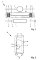
- Fig. 1 illustrates schematically and in simplified form a known from the prior art switching arrangement 1 for a in a fluorescent lamp socket usable LED light tube 2.
- the switching arrangement 1 has a known from the prior art connecting element 3 and a known from the prior art ballast 4.
- the connecting element 3 is connected to a first holder 5 and a second holder 6, both of which serve for fastening the LED tube 2 to a light frame, not shown.
- the connecting element 3 is thus connected in parallel to the LED tube 2.
- the connecting element 3 may comprise a connector, an electrical fuse and / or an electrical conductor.
- two pins 8 are short-circuited at a second end of the LED tube 2.
- two pins 9 are connected to a circuit board 10, which carries a plurality of LEDs 11 of the LED tube 2. The light-emitting diodes 11 are thus supplied with voltage only via the first end of the LED light tube 2.
- the ballast 4 is arranged or wired. Thus, the ballast 4 is connected in series with the LED tube 2.
- a proposed starter replacement means 12 is used instead of the connecting element 3.
- Fig. 2 schematically shows a proposed starter replacement means 12 according to a first embodiment.
- the starter replacement means 12 has a housing 13 for protecting an electronic control unit 14 arranged in the starter replacement means 12.
- the control electronics 14 is connected to two contact pins 15, which are fastened to the housing 13.
- the contact pins 15 are used in particular for receiving the starter replacement means 12 in the fluorescent lamp holder.
- the starter replacement means 12 is used to replace a starter for a fluorescent lamp. Accordingly, the designs and connections of the starter replacement means 12 are preferably compatible with the interfaces of the fluorescent lamp socket.
- the control electronics 14, preferably electrically connected to the contact pins 15, may have a resistor 17 as a component of the control electronics 14. Parallel to the resistor 17, a capacitor 18 and / or a coil 18 may be connected. In addition, another capacitor 18 and / or a further coil 18 connected in series with the resistor 17.
- the control electronics 14 is arranged on a circuit board 16 of the starter replacement means 12, in particular soldered.
- the board 16 is in Fig. 2 indicated by dashed lines.
- the control electronics 14 may have further resistors 17, capacitors 18 and / or coils 19.
- the capacitors 18 are non-electrolytic capacitors.
- Electrolytic capacitors in particular wet-electrolytic capacitors, are known in principle for the fact that they are characterized by a high capacitance density with low capacity-related costs and are therefore used almost exclusively for voltage stabilization in power supplies. Electrolytic capacitors are characterized in that an energy storage is at least partially electrochemical, wherein in wet-electrolytic capacitors, an at least partially liquid electrolyte is used.
- electrolytic capacitors generally represent an optimum cost-benefit ratio for line filters, that is, as capacities for attenuating network frequencies, and that they have no alternative due to the high capacity required. Because according to the proposal are in the control electronics 14 and net filter or other capacity, at least on the output side preferably free of (wet) electrolytic capacitors. Namely, it has surprisingly been found that the travel time extensions and improvements in the reliability of the electrolytic capacitor-free control electronics 14 can overcompensate the possibly higher initial costs when using non-electrolytic capacitors, in particular when using the starter replacement means 12 in luminaires with an LED luminous tube 2 with a plurality of light-emitting diodes 11 ,
- the failure of electrolytic capacitors in known light sources can represent a limiting factor for the duration of the light-emitting means. Therefore, synergistically, the combination of non- (wet) electrolytic capacitors in the control electronics 14 lead with light emitting diodes for light generation to a significantly extended life of the entire bulb.
- electrolytic capacitor-free control electronics 14 but at least an electronic control unit 14 without wet-electrolytic capacitors and / or output side without particular wet-electrolytic capacitors, is preferred.
- the resistors 17, capacitors 18 and / or the coils 19 are designed as SMD components.
- the abbreviation SMD surfacemounted device designates a surface-mounted electrical component. Unlike through hole technology (THT) devices, SMD devices have no wire connections, but are soldered directly onto a circuit board using solderable pads.
- control electronics 14 is designed such that the electrical power of the light source is adjustable or adaptable.
- adjustable and adaptable as used in the context of the present invention, are understood to mean that the electrical power of the light source can be changed during operation of the light source targeted and traceable for a user or fitter.
- the possibility of setting the electrical power of the light-emitting means is therefore an alternative to starter replacement means 12, which can not be adjusted during operation and which has been previously tuned for operation with a specific light source in a fluorescent lamp socket.
- adjustable or “adaptable” should also be understood as meaning a one-time setting or adaptation, preferably also by presetting, etc.
- a non-illustrated adjustment can be used.
- the adjustment is preferably done without tools, z. B. by turning, pushing or clicking.
- the starter replacement means 12 has a ratchet for adjusting the electrical power of the lighting means.
- a plurality of different starter replacement means 12 can be provided, wherein the adjustment can be made by selecting one of the starter replacement means 12.
- the setting of the electrical power of the bulb can be gradual, z. B. via an adjustment with three stages or by different starter replacement means 12, or continuously.
- control electronics 14 is designed such that the luminous flux can be adjusted by adjusting the electrical power of the lamp.
- the electrical power of the luminous means can be set visually perceptible.
- the luminance or the brightness of the light source can be adjusted individually.
- This preferred embodiment makes it possible to flexibly and precisely set a desired luminance distribution. So it may be z.
- the electric power of bulbs arranged in the vicinity of other light sources for example in the vicinity of external windows or the like, are set lower compared to bulbs arranged in darker places.
- control electronics 14 is designed such that by adjusting the electrical power of the lamp, the luminous flux in a range of 0% to 150% of the nominal Lichtströms is adjustable.
- the nominal luminous flux corresponds to the luminous flux according to the marking of the luminous means without adjustability. It is particularly preferred if the luminous flux can be adjusted within a range of 100% to 140% of the nominal luminous flux by means of setting the electrical power of the luminous means.
- Such an adjustable light source can be used, for example, instead of a plurality of separate light sources with fixed luminous flux (eg in a basic version, a high-lumen version and an ultra-high-lumen version).
- a trained control electronics 14 can be used for dimming the lamp.
- the light source can be dimmed individually by means of the starter replacement means 12, ie on the light itself.
- Retrofitting the starter replacement means 12 is simple and inexpensive to implement. In particular, retrofitting the starter substitute 12 does not require routing of cables.
- the starter replacement means 12 is formed such that the starter replacement means 12 compensates for that change in the electrical power of the bulb, by electrically connecting the current limiting serving Vorschaltstoffs 4 of the fluorescent lamp socket and one of the supply particular gas discharge lamp serving electronics of the bulb and / or a socket or lamp is caused.
- a light source in the lamp can be formed by the capacitors of the electronics and / or the inductance (choke) of the ballast 4, an electrical resonant circuit, in particular an electrical series resonant circuit.
- the starter replacement means 12 can now be designed such that the starter replacement means 12 compensates for the change in the input power consumption of the light source caused by the electrical resonant circuit.
- starter replacement means 12 allows a supply of the control electronics of the lamp with mains voltage, that is, a connection to the power grid.
- Mains voltage in the context of the present invention is a voltage that can be, for example, between 80 and 800 V, in particular 230 V, 380 V or 110 V AC and / or about the house installation o. The like. Is available. It is therefore preferred that the starter replacement means 12 allows operation of the light source on the public power grid.
- FIG. 3 schematically shows the structure of a second embodiment of a starter replacement means 12 according to the invention without the housing 13th
- the starter replacement means 12 according to the in Fig. 3 illustrated embodiment has a housing bottom 20 and a circuit board 19 '. On the board 19 'three identical or different electrical components 21 are arranged.
- the components 21 may, for. B. capacitors, resistors and coils include. This embodiment allows a compact design of the starter replacement means 12th
- Fig. 4 schematically shows a front view of a luminaire 22 according to the invention.
- the luminaire 22 may have a fluorescent lamp holder 23, an LED tube 2 which can be inserted into the fluorescent lamp holder 23 and which has a plurality of light-emitting diodes 11, a current-limiting means 4 and / or a starter replacement means 12.
- the starter replacement means 12 is formed like the previously described inventive starter replacement means 12.
- the LED luminous tube 2 preferably has at least one first circuit board 19 "which carries the light-emitting diodes 11.
- the LED tube 2 has a control electronics for supplying the LEDs 11. It is preferred that the LED light tube 2 has a connection means, not shown, for connecting the control electronics to the mains voltage. Furthermore, it is preferred for the first circuit board 19 "to carry the control electronics or at least significant parts of the control electronics. Preferably, the control electronics are constructed without transformers and / or at least on the output side exclusively with non-electrolytic capacitors.
- the LED tube 2 is formed cable-free.
- the LED light tube 2 preferably has a preferably tubular housing 24 and / or an at least substantially transparent or translucent cover of the housing 24, which is particularly preferably polymethylmethacrylate (PMMA), or at least substantially consist of PMMA / exist.
- PMMA polymethylmethacrylate
- a PMMA cover is excellent in visible light transmittance, has high UV resistance and shock properties, and does not yellow in contrast to conventional polycarbonate covers. So far, polycarbonate is used because of its higher temperature resistance, but has poorer transmission properties and yellows after a short time. Consequently, a PMMA cover can realize a shock-resistant LED luminous tube 2 with improved UV resistance, whose luminosity and efficiency are improved due to improved transmission properties of the cover and whose function is not degraded over time due to yellowing effects. By using the cover made of PMMA, therefore, the efficiency of the LED luminous tube 2 can be improved by the fact that light output emitted by the outstanding transmission properties of the cover can be increased.
- the present invention preferably or additionally prefers an LED luminous tube 2 with a control electronics which is transformer-free and / or has at least the output side exclusively with non-electrolytic capacitors.
- a control electronics which is transformer-free and / or has at least the output side exclusively with non-electrolytic capacitors.
- a second cover may be connected to the translucent cover, in particular clamping and / or latching or positive and / or non-positive.
- the second cover is preferably made of a heat-dissipating material, in particular aluminum, steel or the like, but may also comprise or consist of PMMA and / or polycarbonate (PC).
- the second cover may have grooves, beads or cooling ribs, in particular on the outside and / or along the housing 24 to promote heat dissipation into the environment for cooling the LED light tube 2.
- the entire housing 24 - with the first and / or the second cover - made of plastic, in particular PMMA and / or polycarbonate, or comprise PMMA or polycarbonate.
- plastic in particular PMMA and / or polycarbonate
- PMMA or polycarbonate a particularly robust LED tube 2 which can emit light in several directions at the same time or be sealed against water or other chemicals. Nevertheless, the use of any other plastic or a metal or other material is possible.
- PMMA for the preferably entire housing 24 is particularly preferred, since with PMMA an LED luminous tube 2 is made possible, which is at least substantially not yellowed and / or UV-resistant. It can be provided that the housing 24 is metal-free and / or free of cooling ribs.
- control electronics 14 preferably forms part of the control electronics.
- the control electronics can be designed to allow operation of light-emitting diodes, in particular of LEDs 11 of the LED tube 2, a network voltage.
- the control electronics 14 may be a starter replacement means 12 associated, in particular arranged in this part of the control electronics.
- the control electronics can at least partially in the starter replacement means 12 may be arranged or associated with this.
- the control electronics now explained below and the control electronics 14 of the starter replacement means 12 can also be implemented individually and independently. It is particularly preferred that the control electronics 14 is adjustable by means of the control electronics. In particular, it can be provided that by selecting a suitable starter replacement means 12, a corresponding control electronics 14, the control electronics complements, in particular such that a desired power, input power and / or light output of the LED tube 2 or other illuminant results.
- control electronics on a constant current regulator, which forms a series circuit, hereinafter called load loop with the series-connected LEDs 11.
- control electronics transformer-free, (throttle) coil-free and / or at least the output side constructed exclusively with non- (wet) electrolytic capacitors.
- the series circuit of the constant current regulator and a plurality of light emitting diodes 11 is used.
- This series circuit which is also called a load loop, can be operated at comparatively high voltages, which can eliminate the need for a transformer.
- a very compact design can be achieved with low power dissipation.
- an operating voltage of the load loop at least substantially a sum of the forward voltages of the series-connected light emitting diodes 11 and the operating or rated voltage of the constant current regulator and / or more than 20%, preferably more than 40%, in particular more than 50% of the rectified and smoothed or effective rated voltage correspond.
- the voltage applied to the load loop is distributed over its elements, that is to say at least via the constant current regulator and the light-emitting diodes 11 connected in series therewith.
- the load loop is designed such that only a small proportion of the total voltage applied to the load loop drops at the constant current regulator. This proportion is preferably below 50%, more preferably below 30%, in particular below 20% and particularly preferably below 10% or 8%.
- the forward voltages correspond to the light emitting diodes connected in series 11 more than 50%, more preferably more than 70%, preferably more than 80% and particularly preferably more than 90% or 94% of the voltage applied to the load loop voltage. A drop of only a small fraction of the total voltage across the constant current regulator allows a minimum remaining power dissipation in the constant current regulator.
- control electronics is designed such that when using an input power reducing starter replacement means 12 of the constant current regulator its operating voltage is no longer reached and smoothing the then wavy voltage to the light emitting diodes 11 is capacitively blocked. This facilitates the control of the power or input power consumption of the LED light source 2 or other light source by the proposed starter replacement means 12.
- the load loop is supplied with rectified mains voltage via a rectifier.
- a rectifier This may preferably be a semiconductor and / or bridge rectifier.
- the light-emitting diodes 11 are preferably supplied with DC voltage or a preferably smoothed rectified AC voltage or with a direct current or a preferably smoothed rectified current for uniform light output.
- the current regulator is preferably designed for operation with a DC voltage or direct current. The use of a rectifier or bridge rectifier advantageously makes it possible to supply the load loop with DC voltage or direct current. Remaining ripple of the rectified voltage or the rectified current is preferably compensated or regulated by the constant current regulator.
- the rectifier for supplying mains voltage can be capacitively coupled to the connection means, preferably exclusively with one or more non-electrolytic capacitors.
- the capacitive coupling of the rectifier with the mains voltage or with the connection means for connecting the control electronics to the power supply system acts as a capacitive series resistor. It can therefore be provided that the capacitance value of a capacitor forming the capacitive coupling is designed such that a voltage drop at this capacitor results operationally, preferably whereby the voltage amplitude at the rectifier or the voltage at the load loop can be adjusted.
- this capacitor has a reactance at mains frequency, for example between and / or at least substantially 50 Hz or 60 Hz, such that the voltage at the load loop is at least substantially the sum of the forward voltages of the light emitting diodes connected in series to form the load loop 11 and the rated voltage of the current regulator is reduced.
- the capacitor which is designed for the electrical connection of the rectifier to the connection means, a voltage applied to an input of the rectifier voltage to less than 80%, preferably less than 70%, in particular less than 50% and / or more than 10%, preferably more than 20%, in particular more than 30% of a voltage applied to the connection means mains voltage reduced or causes a corresponding voltage drop between its terminals.
- a reactance within the meaning of the present invention is preferably an at least substantially imaginary resistance in the sense of AC calculation, also called reactance.
- a reactance in particular a capacitance, advantageously makes it possible to reduce the voltage without causing larger amounts of heat or power loss.
- At least one preferably non-electrolytic capacitor is provided parallel to the light-emitting diodes 11 connected in series. This makes it possible to smooth the current flowing through the LEDs current and / or to achieve a more uniform light output of the lamp.
- the control electronics may have a plurality of constant current regulator, which are preferably electrically connected to one another on the input side.
- the constant current regulator can be supplied with power together. It is possible that several load loops are each provided with a constant current regulator connected in series with a plurality of light-emitting diodes 11. Alternatively or additionally, it is possible that the constant current regulator are electrically connected to one another on the load side. As a result, a larger current intensity can be achieved or regulated by the LEDs 11.
- the load loop is connected via a resistor to the rectifier. This may be conducive to a short-circuit withstand voltage of the luminous means and / or the current control by the constant-current regulator.
- the constant current regulator is preferably designed to keep a current through the light emitting diodes 11 of the load loop at least substantially constant, in particular with deviations from a desired value for the current through the light emitting diodes 11 less than 30%, preferably less than 20%, in particular less than 10 %.
- the setpoint value for the current through the light emitting diodes 11 is preferably greater than 10 mA, in particular more than 20 mA and / or less than 1 A, in particular less than 500 mA. This is the life of the LEDs 11 conducive.
- the constant-current regulator may be connected to the resistor, in particular wherein the resistor is used as a shunt resistor.
- the resistor is used as a shunt resistor.
- a voltage dropping across the resistor is used as a control variable for the current regulation by the constant current regulator.
- a control input of the constant current regulator in particular by means of a series resistor, electrically conductively connected to the output of the constant current regulator. The signal applied to the control input or the applied level can be used to control the current flow of the constant current regulator.
- the output of the constant-current regulator preferably faces the light-emitting diodes 11 connected in particular in series or connected to these electrically conductive.
- the input of the constant-current regulator can be facing the rectifier or electrically connected to it.
- control electronics which is preferably supplied with mains voltage, preferably transformer-free, so constructed without transformers.
- mains voltage preferably transformer-free
- transformer-free design of the control electronics or the lighting means avoid or reduce power dissipation or heat generation.
- switching power supplies which are also usually constructed with transformers, transformers and / or (throttle) coils, which is preferably avoided here in order to reduce the power loss.
- transformers or coils by the winding process consuming and expensive to produce and require a lot of space in the housing of bulbs.
- the transformer-free or coil-free construction of the control electronics thus enables a more cost-effective, more compact lighting means.
- the term "transformer” is to be understood as meaning preferably any coupled inductors, in particular also coupled coils or transformers.
- control electronics are constructed exclusively with non-electrolytic or at least non-wet electrolytic capacitors.
- the first circuit board 19 " carries the control electronics or at least significant parts of the control electronics, ie the same circuit board is used to support both light emitting diodes 11 and the control electronics for the light-emitting diodes 11 and the control electronics are dispensed side by side or each other in a housing of the lamp and the light source can be made more flexible, smaller or with a smaller diameter. It can be provided that the control electronics exclusively in the LED bulbs 2, in particular on the board 19 ", and is provided in the starter replacement means 12.
- the material for the additional board is saved and an error-prone cable connection between the control electronics and the board 19 "with the light-emitting diodes 11 can be avoided, which is additionally advantageous in view of the production effort, since previous cable connections between different boards are generally not automated can be prepared and therefore are particularly expensive.
- a proposed illuminant has at least one second circuit board with a plurality of light-emitting diodes. Between the first, the second and / or further board, an electrically conductive connector for supplying the LEDs of the second and / or further board can be made by the control electronics.
- control electronics or essential parts of these on the first board 19 "and the use of the plug connection can each avoid an error-prone use of cable connections without cable connections.
- the proposed illuminant are preferably several, in particular coupled with conductive connectors, boards 19 "used with light-emitting diodes 11, of which at least one, preferably the front side arranged in the light source board 19" carries at least significant parts of the control electronics. This allows the use of the same control electronics in different bulbs at the same time reduced space requirements, improved reliability and easier and cheaper installation.
- the lighting means has the first circuit board 19 "with a plurality of light emitting diodes 11 and at least the second circuit board with a plurality of light emitting diodes 11, preferably wherein between the boards an electrically conductive connector for supplying the light emitting diodes of the second board is made by the control electronics and / or wherein the LEDs 11 of the second board in series with the LEDs 11 of the first board 19 "are connected.
- the light emitting diodes 11 of the first board 19 "and the second board may form one or more separate load loops with one or more constant current regulators, preferably wherein the one or more constant current regulator (s) are arranged on the first board, Alternatively or additionally, it is possible that the first, Second and / or further board each having a load loop with a constant current regulator and a plurality of light-emitting diodes 11. This may be a simple modular scalability beneficial.
- the load loops of the respective boards are supplied by the first board 19 "and / or with a common rectifier and / or via the plug connection
- the second or further board can comprise at least one component, in particular one Capacitor or resistor, for adaptation of the control electronics when using additional boards, which is preferably connectable via the connector to the first board or to the control electronics.
- a cable or a cable connection in the context of the present invention is a preferably flexible, flexible and / or in particular radially and / or at least partially surrounded by an insulation electrical conductor which is at least partially free in space laying.
- a cable according to the present invention may be or have a stranded wire, a bell wire or the like.
- a rigid and / or at least partially or essentially non-insulated, electrically conductive connecting pin does not constitute a cable in the sense of the present invention.
- a lighting means in the context of the present invention is preferably a means for emitting electromagnetic waves in the optically visible region, which is particularly suitable for illuminating rooms, floors, walls, ceilings, objects, outdoor areas or the like.
- the light-emitting means is therefore preferably suitable for providing a sufficient amount of light for illumination, improving its visibility by illumination of an object or emitting a sufficient amount of light, for example a luminous flux of more than 10 lumens, preferably more than 100 lumens, in particular more than 300 lumens so that this amount of light can be perceived by a human eye even after reflection by an object.
- a light-emitting means is therefore in particular not a pure status LED or the like which, although it can also light up, but in which primarily or exclusively the direct light emission is used as a display.
- a board in the sense of the present invention is a preferably plate-shaped arrangement with an insulating and a conductive material, preferably wherein the insulating material or dielectric forms a support for at least one line of the conductive material.
- the circuit board may be one for printed circuits, a so-called “printed circuit board” or PCB, in particular epoxy-based (insulating material) and / or copper-clad (conductive material).
- the starter replacement means 12 a parallel circuit of the capacitor 18 to the resistor 17, wherein the nodes of the parallel circuit are directly connected to the contact pins 15 of the starter replacement means 12.
- the capacitor 18 is preferably designed as a capacitive series resistor. It can be provided that the preferably non-electrolytic capacitor 18 and / or the starter replacement means 12 between the contact pins 15 has a capacity which is more than 1 uF and / or less than 100 uF, preferably more than 2 uF and / or less than 20 uF, in particular more than 2.5 uF and / or less than 10 uF corresponds.
- the resistor 17 may be designed to slowly discharge the capacitor 18, so that when removing the starter replacement means 12 from a lamp holder 23, the risk of electrical discharge via the contact pins 15 can be reduced.
- the value of the resistor 17 may be more than 50 k ⁇ , preferably more than 100 k ⁇ , in particular more than 200 k ⁇ , more preferably between 400 k ⁇ and 600 k ⁇ , and / or less than 10 M ⁇ , preferably less than 5 M ⁇ , in particular less than 1 M ⁇ amount.
- the value of the capacitor 18 is adjustable in stages.
- the capacitor 18 is composed of several components.
- the capacitor 18 may be formed in particular by a capacitor array. It can be provided that the components or individual capacitors can be connected in different ways in such a way that the capacitor 18 and / or the capacitance between the contact pins 15 of the starter replacement means 12 results in different values.
- a plurality of parallel branches may be provided with capacitors between the contact pins 15 of the starter replacement means 12, wherein one or more switches may be provided in series with the respective capacitor, which can disconnect one or more of these branches and / or de-energize.
- DIP switches can be used to affect capacity.
- the capacitor 18 has a parallel connection of a plurality of capacitive components in parallel-connected branches, which can be at least partially deactivatable by switches.
- different capacitance values are assigned to the different branches, in particular wherein, starting from a first branch having a minimum capacitance value, each further branch has a capacity doubled to the preceding branch. This allows fine adjustment of the capacitance value over a wide range using as few devices as possible.
- control electronics can be implemented individually and in different sub-combinations.
- the load loop can be used with DC voltage without the DC voltage is generated by a capacitor and / or a rectifier. It is also possible to use the control electronics instead of LEDs with other consumers.
- the control electronics will be explained in more detail using an exemplary embodiment, wherein components, advantages and properties of the preceding description of a control electronics which may correspond to the control electronics of the following description.
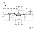
- Figure 5 shows a circuit diagram of a proposed control electronics 104 as an exemplary embodiment of the previously in connection with the starter replacement means 12 generally shown control electronics.
- the control electronics 104 can also be realized independently of other aspects of the present invention and in particular independently of the starter substitute.
- connection means 105 is provided to supply the control electronics 104 with mains voltage, which in Fig. 5 is indicated by the arrow U.
- the connection means 105 may correspond to one or more contact pins 15 or vice versa.
- a rectifier 118 is capacitively coupled to the connection means 105 in the illustration example.
- at least one capacitor 18 is provided, via which the connection means 105 is electrically conductively connected to the rectifier 118.
- the capacitor 18 may also be formed by a plurality of components, in particular by a capacitor bank with a plurality of capacitors in series connection and / or parallel connection. It may thus be provided, for example, that the capacitor 18 is formed by a parallel connection of a plurality of series circuits of individual capacitors.
- the capacitor 18 is preferably arranged completely or partially in the starter replacement means 12 or forms part of the starter replacement means 12.
- the resistor 17 and / or the coil 19 can be provided alternatively or additionally, even if they are in Fig. 5 are not shown for reasons of simplification.
- the starter replacement means comprises the capacitor 18 completely or partially in parallel with the resistor 17, as described above.
- the capacitor 18 may be configured to operatively generate a voltage drop such that the line voltage reaches the rectifier 118 at a reduced amplitude.
- the capacitor 18 or the control electronics 104 is designed such that the amplitude of the voltage at the input 118A of the rectifier 118 is less than 80%, preferably less than 70%, in particular less than 50% and / or more than 5%, preferably more than 10%, in particular more than 20% corresponds to the mains voltage amplitude.
- the capacitance of the capacitor 18 may be more than 1 ⁇ F, preferably more than 2 ⁇ F, in particular more than 3 ⁇ F and / or less than 100 ⁇ F, preferably less than 50 ⁇ F, in particular less than 20 ⁇ F.
- the rectifier 118 may include one or more diodes and / or transistors.
- the rectifier 118 is constructed as a bridge rectifier or has such. This allows a high efficiency of the rectifier 118 and a correspondingly lower power loss can be achieved.
- Rectifier 118 is preferably configured to generate a DC voltage or rectified voltage at its output 118B from an AC voltage at its input 118A. The mains voltage which is preferably reduced in amplitude by the capacitor 18 can therefore be supplied to the rectifier 118, which can generate a corresponding DC voltage therefrom. This DC voltage can then be used to operate the LEDs 3, 109.
- only one light-emitting diode 11 is shown in the circuit diagram from FIG. 105, even if this may be a series connection, parallel connection or combination of series and parallel connection of a plurality of light-emitting diodes 11. As in the illustration of FIG. 105, however, only one light-emitting diode 11 can be provided. However, at least one series connection of a plurality of light-emitting diodes 11 that can extend over a plurality of circuit boards is particularly preferred. It is thus preferable to replace the diode symbol or the light-emitting diode 11 in the exemplary embodiment from FIG. 105 by a series connection of a plurality of light-emitting diodes 11, which is not shown for better clarity. Furthermore, it is possible for light-emitting diodes 11 to be arranged parallel to one another, in particular for a plurality of series connections of light-emitting diodes 11 to be arranged parallel to one another.
- the light-emitting diodes 11 preferably form a series connection with a constant current regulator 120, this series connection also being called a load loop.
- the constant current regulator 120 also called “constant current regulator” or CCR, is preferably designed to keep a current constant or to compensate for fluctuations in current and / or to limit a current.
- the constant current regulator 120 in the illustration example is designed to keep a preferably preset or predefined current 121 constant, in particular, by regulating or regulating a voltage drop through the constant current regulator 120 by controlling an impedance. This impedance can be increased with increasing current and / or reduced with decreasing current, whereby a current change can be counteracted.
- other control mechanisms are also possible in order to stabilize the current 121 with the constant-current regulator 120, to regulate it or to keep it constant.
- the current 121 through the load loop and / or the light emitting diodes 11 is therefore preferably determined by the constant current regulator 120, in particular regulated.
- an optional tap may be provided at the output 120B of the constant current regulator 120, which may be connected to a control input 120C of the constant current regulator 120, in particular via a dropping resistor 122.
- the current 121 controlled by the constant current regulator 120 is preferably used to operate the light emitting diodes 11.
- the constant current regulator 120 with its output 120 B can be conductively connected to the light-emitting diodes 103, 109.
- the output 120B of the constant-current regulator 120 has a capacitor 123, preferably with the capacitor 123, the current 121 output from the constant-current regulator 120 can be stabilized.
- the capacitor 123 is designed to compensate for voltage changes at the output 120B of the constant-current regulator 120 or at the light emitting diodes 11.
- the capacitor 123 may be formed and electrically connected such that at a voltage or current change at the output 120B of the constant current regulator 120, a current flows in or out of the capacitor 123, whereby a voltage change is counteracted.
- the capacitor 123 is preferably formed of a plurality of capacitors. It can be provided that the capacitor 123 has one or more series circuits or parallel circuits of capacitors, in particular a parallel circuit of a plurality of series circuits of capacitors.
- a connection bank with a variety of connection options for capacitors. This allows individual assignment and thus scaling of the capacitor 18 and / or the capacitor 123, without any changes to the board layout would be necessary.
- the control electronics 104 at least on the output side is formed electrolytic capacitor-free.
- the capacitor 23 or the capacitor 23 forming capacitors or components is or are exclusively non-electrolytic type. It can thus be achieved that compensating currents which charge or discharge the capacitor 23, in particular in order to stabilize the output voltage or the output current of the constant current regulator 118, do not or only to a very small extent Part are converted by the internal resistance of the capacitor 123 into heat.
- a loss factor in the sense of the present invention describes the ratio of imaginary part to real part of an impedance, in particular of the capacitor 18 or 23, preferably at mains frequency, in particular at 50 or 60 Hz. It is therefore preferred that at least the output-side capacitor 123 and / or the capacitor 18, but optionally also other or all capacitors of the control electronics 104, a loss factor less than 5%, preferably less than 4%, in particular less than 3%, in particular at frequencies greater than 45 Hz and / or less than 65 Hz. This can increase the efficiency of the light source and reduce heat generation.
- the load loop can be connected to the rectifier 118 via a (pre) resistor 124.
- the resistor 124 may thus be connected in series with the constant current regulator 120 and the light-emitting diodes 11.
- Resistor 124 is preferably for short circuiting, current limiting, and / or adjusting the operating voltage for constant current regulator 120.
- Resistor 124 may be composed of a plurality of resistors, which in turn may form a series connection, a parallel connection, and / or a series connection of series circuits.
- the rectifier 118 is preferably designed as a bridge rectifier. Alternatively or additionally, however, it may also be possible for a simple rectifier, for example only a rectifier diode, to be used to form the rectifier 118.
- the load loop in particular via the resistor 124, can be connected directly to the mains voltage connection means 105. So it may be sufficient that the constant current regulator 120 is supplied via the rectifier 118 with rectified mains voltage.
- the capacitor 18 is also possible for the capacitor 18 to be divided between different conductive connections between the connection means 105 and the rectifier 118. This is especially true when the rectifier 118 has a bridge rectifier or is designed as a bridge rectifier.
- starter replacement means 12 and the control electronics 104 can be realized independently of each other.
- Fig. 6 shows a kit K with an LED illuminated tube 2 and at least one, preferably at least two, in the illustrated example, three, preferably four or more starter Optimizmittetetn 12. Details of the LED tube 2 and the starter replacement means 12 are not shown only for reasons of clarity again.
- the starter replacement means 12 of the kit K are preferably designed differently.
- the starter replacement means 12 are designed for different control of the electrical power, in particular the input power consumption, of the LED light-emitting tube 2.
- the starter replacement means 12, preferably exclusively non-electrolytic, capacitors 18 having different values and / or between the contact pins 15 have different capacitance values.
- the capacitance value of a second starter replacement means 12 is more than 1.5 times and / or less than 3 times the capacitance value of a first starter replacement means 12 of the kit.
- the first and / or lowest capacitance value can be greater than 1 ⁇ F and / or less than 5 ⁇ F.
- the kit K is preferably designed in such a way that the light-emitting diodes 11 of the LED light-emitting tube 2 are supplied via an electronic control unit which, for one part, is arranged in the LED light-emitting tube 2 and, on the other hand, in the starter replacement means 12 is, so that the properties of the control electronics, preferably in relation to the control of the electrical power of the LED tube 2, by the choice of one of the different starter replacement means 12 is adjustable.
- This can be influenced by the proposed kit K in a synergistic manner, the brightness of the LED tube 2 and a malfunction by using false starter or starter replacement means can be avoided.
- the control electronics preferably corresponds wholly or partially to the control electronics 104 Fig. 5 , in particular wherein the capacitor 5 is at least partially disposed in the starter replacement means 12. But it is also a combination with an alternative control electronics possible.
- the starter substitute can also form part of the alternative control electronics here.
- the electrical power of the light source, in particular the LED light tube 2 by selecting the starter replacement means 12 be adjustable, configurable or selectable.
- the capacitor 18 or the capacity thus called between the contact pins 15 of the starter replacement means 12 can be used as a so-called capacitive series resistor, which can reduce the power consumption of the LED luminous tube 2.
- a starter replacement means 12 may be configured to be adjustable, in particular with respect to the capacitor 18 or the capacitance between the contact pins 15 of the starter replacement means 12.
- At least one of the starter replacement means 12 is designed to take into account, in particular to compensate, a ballast 4 of the fluorescent lamp socket 23.
- the ballast 4 may in particular be a throttle, but also electronic ballasts or the like.
- one aspect of the present invention relates to a starter replacement means 12 specially designed for this purpose, which is designed to enable the operation of the LED arc tube 2 also with such a ballast means 4.
- the capacitance of the capacitor 18 can be dimensioned such that this can be achieved by inserting the starter replacement means 12 into the fluorescent lamp holder 23 or in electrical connection of the starter replacement means 12 with the ballast 4 forms a series resonant circuit with a resonant frequency, which preferably at least substantially the mains frequency (50 Hz or 60 Hz) corresponds.
- a corresponding starter replacement means 12 is preferably part of the proposed kit. With the kit K can thus be ensured that the LED light tube 2 can be operated both with fluorescent lamp sockets 23 with and without ballast 4.
- the starter replacement means 12 may also be designed both for operation with a ballast and for adjusting the power of the lamp.
- kit K includes the LED light tube 2 and four different starter replacement means 12.
- the different starter replacement means 12 may have the colors green, blue, orange and / or red.
- the green starter replacement means leads to a lower input power consumption of the illuminant which can be inserted into the fluorescent lamp socket 23 in comparison to any other starter replacement means 12 attached to the kit K.
- a starter replacement means 12 marked with red can lead to the highest power consumption in comparison to the other starter replacement means 12 attached to the kit K.
- a blue and / or orange starter replacement means 12 may result in different average power consumptions.
- the kit K may be characterized in that its components, ie at least one starter replacement means 12 and a light source, preferably an LED light tube 2, are characterized by means associated with one another, connected to each other or otherwise associated with each other. In particular, these components are arranged in a common or in associated packages. Alternatively or additionally, the components may include one or more associated or common instructions, descriptions, hints and / or designations or markings. However, the affiliation of the components to the kit K can alternatively or additionally also be indicated in any other way and with other means.
- the drive electronics 104 can also be realized independent of the starter replacement means 12 and independently of the LED tube 2 or the arrangement in this.
- the kit K can be realized without the control electronics 104.
- simultaneous implementation of several aspects of the present invention is preferred.
Landscapes
- Circuit Arrangement For Electric Light Sources In General (AREA)
Priority Applications (1)
| Application Number | Priority Date | Filing Date | Title |
|---|---|---|---|
| EP13000725.5A EP2629588A1 (fr) | 2012-02-14 | 2013-02-13 | Moyen de remplacement de démarreur avec un capaciteur, pour un dispositif de lampe à substance fluorescente |
Applications Claiming Priority (5)
| Application Number | Priority Date | Filing Date | Title |
|---|---|---|---|
| DE201210002710 DE102012002710A1 (de) | 2012-02-14 | 2012-02-14 | LED-Leuchtmittel |
| DE102012004160 | 2012-03-05 | ||
| DE201210004334 DE102012004334A1 (de) | 2012-03-05 | 2012-03-07 | Starterersatzmittel für eine Leuchtstofflampenfassung |
| EP13000442 | 2013-01-30 | ||
| EP13000725.5A EP2629588A1 (fr) | 2012-02-14 | 2013-02-13 | Moyen de remplacement de démarreur avec un capaciteur, pour un dispositif de lampe à substance fluorescente |
Publications (1)
| Publication Number | Publication Date |
|---|---|
| EP2629588A1 true EP2629588A1 (fr) | 2013-08-21 |
Family
ID=47789937
Family Applications (1)
| Application Number | Title | Priority Date | Filing Date |
|---|---|---|---|
| EP13000725.5A Withdrawn EP2629588A1 (fr) | 2012-02-14 | 2013-02-13 | Moyen de remplacement de démarreur avec un capaciteur, pour un dispositif de lampe à substance fluorescente |
Country Status (1)
| Country | Link |
|---|---|
| EP (1) | EP2629588A1 (fr) |
Cited By (1)
| Publication number | Priority date | Publication date | Assignee | Title |
|---|---|---|---|---|
| CN107332397A (zh) * | 2017-07-28 | 2017-11-07 | 广东美芝制冷设备有限公司 | 压缩机及空调器 |
Citations (7)
| Publication number | Priority date | Publication date | Assignee | Title |
|---|---|---|---|---|
| DE102007044339A1 (de) * | 2007-09-17 | 2009-03-19 | Tridonicatco Gmbh & Co. Kg | Leuchtdioden-Modul und Verfahren zur Steuerung eines Leuchtdioden-Moduls |
| DE202010005615U1 (de) | 2010-04-27 | 2010-09-30 | Schmelter, Joachim | LED-Leuchtröhre |
| DE202010010536U1 (de) | 2010-07-22 | 2010-11-18 | Asmetec Gmbh | LED-Röhre mit einseitiger Kontaktierung und Sicherungstechnologie |
| WO2011112467A2 (fr) | 2010-03-08 | 2011-09-15 | Microsoft Corporation | Configurations de déploiement d'application logicielle virtuelle |
| WO2011124670A1 (fr) | 2010-04-08 | 2011-10-13 | Valtavalo Oy | Lampe à diode électroluminescente et tube à diode électroluminescente pour équiper ultérieurement un éclairage fluorescent |
| EP2381158A2 (fr) * | 2010-04-23 | 2011-10-26 | Teknoware Oy | Tube DEL et agencement de lampe |
| WO2012052875A2 (fr) * | 2010-10-19 | 2012-04-26 | Koninklijke Philips Electronics N.V. | Lampe à diode électroluminescente pour conversion |
-
2013
- 2013-02-13 EP EP13000725.5A patent/EP2629588A1/fr not_active Withdrawn
Patent Citations (7)
| Publication number | Priority date | Publication date | Assignee | Title |
|---|---|---|---|---|
| DE102007044339A1 (de) * | 2007-09-17 | 2009-03-19 | Tridonicatco Gmbh & Co. Kg | Leuchtdioden-Modul und Verfahren zur Steuerung eines Leuchtdioden-Moduls |
| WO2011112467A2 (fr) | 2010-03-08 | 2011-09-15 | Microsoft Corporation | Configurations de déploiement d'application logicielle virtuelle |
| WO2011124670A1 (fr) | 2010-04-08 | 2011-10-13 | Valtavalo Oy | Lampe à diode électroluminescente et tube à diode électroluminescente pour équiper ultérieurement un éclairage fluorescent |
| EP2381158A2 (fr) * | 2010-04-23 | 2011-10-26 | Teknoware Oy | Tube DEL et agencement de lampe |
| DE202010005615U1 (de) | 2010-04-27 | 2010-09-30 | Schmelter, Joachim | LED-Leuchtröhre |
| DE202010010536U1 (de) | 2010-07-22 | 2010-11-18 | Asmetec Gmbh | LED-Röhre mit einseitiger Kontaktierung und Sicherungstechnologie |
| WO2012052875A2 (fr) * | 2010-10-19 | 2012-04-26 | Koninklijke Philips Electronics N.V. | Lampe à diode électroluminescente pour conversion |
Cited By (1)
| Publication number | Priority date | Publication date | Assignee | Title |
|---|---|---|---|---|
| CN107332397A (zh) * | 2017-07-28 | 2017-11-07 | 广东美芝制冷设备有限公司 | 压缩机及空调器 |
Similar Documents
| Publication | Publication Date | Title |
|---|---|---|
| DE102010008876B4 (de) | Lichtquelle mit Array-LEDs zum direkten Betrieb am Wechselspannungsnetz und Herstellungsverfahren hierfür | |
| DE112010004782B4 (de) | Betrieb einer LED-Leuchte mit variablem Spektrum, Steuereinheit und LED-Leuchte | |
| HK1243476A1 (zh) | 用於带镇流器及不带镇流器的荧光管替换的led管驱动电路 | |
| US20080094837A1 (en) | LED Lamp Suitable as a Replacement for Fluorescent Lamp in Vending Machines | |
| DE112012003338T5 (de) | Wechselstrom-Gleichstrom-LED-Beleuchtungsvorrichtungen, -Systeme und -Verfahren | |
| DE102016100710A1 (de) | Bestromungsbaugruppe, Leuchte und Beleuchtungssystem | |
| DE69928857T2 (de) | Leuchtstofflampe mit eigenem Vorschaltgerät und Leuchte | |
| DE2816715C2 (de) | Speiseschaltung für Leuchtstoffröhren | |
| DE102020113285A1 (de) | Internet-der-dinge-adaptierbare einbauleuchte | |
| DE102010003266A1 (de) | Schaltungsanordnung zum Betreiben einer Retrofitlampe und Retrofitlampe | |
| DE112013001316T5 (de) | LED-Anordnung für den Ersatz von Leuchtstoffröhren | |
| EP3154316A1 (fr) | Lampe à del avec circuit de commande | |
| DE202005006053U1 (de) | Energiesparlampe | |
| DE202010001098U1 (de) | Gelblicht-Röhre auf LED-Basis | |
| EP2613079A1 (fr) | Moyen d'eclairage à DEL | |
| EP2378839A2 (fr) | Lampe à DEL et éclairage | |
| DE202010013108U1 (de) | Steuerungselektronik und Leuchtkörper zum Austausch von Lampen | |
| DE102012002710A1 (de) | LED-Leuchtmittel | |
| EP2629588A1 (fr) | Moyen de remplacement de démarreur avec un capaciteur, pour un dispositif de lampe à substance fluorescente | |
| DE102015109351A1 (de) | Beleuchtungssteuereinrichtung, beleuchtungsbaugruppe und leuchte | |
| DE102017100413A1 (de) | Stromversorgung, Bestromungssystem, Beleuchtungssystem und Verfahren zum Reduzieren der für das Löschen eines Lichtbogens erforderlichen Zeit | |
| DE102020111798B4 (de) | Treiberschaltung für Beleuchtungsmittel, Lampe und Verfahren zum Betreiben einer Lampe | |
| DE102012004334A1 (de) | Starterersatzmittel für eine Leuchtstofflampenfassung | |
| DE102018119656A1 (de) | Mechanischer und elektrischer Aufbau einer Langfeldleuchte und dazugehörige unterschiedliche Betriebsweisen | |
| DE202017002443U1 (de) | Schaltungsanordnung zum Betreiben eines Leuchtmittels |
Legal Events
| Date | Code | Title | Description |
|---|---|---|---|
| PUAI | Public reference made under article 153(3) epc to a published international application that has entered the european phase |
Free format text: ORIGINAL CODE: 0009012 |
|
| AK | Designated contracting states |
Kind code of ref document: A1 Designated state(s): AL AT BE BG CH CY CZ DE DK EE ES FI FR GB GR HR HU IE IS IT LI LT LU LV MC MK MT NL NO PL PT RO RS SE SI SK SM TR |
|
| AX | Request for extension of the european patent |
Extension state: BA ME |
|
| 17P | Request for examination filed |
Effective date: 20140129 |
|
| RBV | Designated contracting states (corrected) |
Designated state(s): AL AT BE BG CH CY CZ DE DK EE ES FI FR GB GR HR HU IE IS IT LI LT LU LV MC MK MT NL NO PL PT RO RS SE SI SK SM TR |
|
| STAA | Information on the status of an ep patent application or granted ep patent |
Free format text: STATUS: THE APPLICATION IS DEEMED TO BE WITHDRAWN |
|
| 18D | Application deemed to be withdrawn |
Effective date: 20150901 |