EP2630379B1 - Cardan flexible compact et engin spatial comportant un tel cardan - Google Patents
Cardan flexible compact et engin spatial comportant un tel cardan Download PDFInfo
- Publication number
- EP2630379B1 EP2630379B1 EP11767736.9A EP11767736A EP2630379B1 EP 2630379 B1 EP2630379 B1 EP 2630379B1 EP 11767736 A EP11767736 A EP 11767736A EP 2630379 B1 EP2630379 B1 EP 2630379B1
- Authority
- EP
- European Patent Office
- Prior art keywords
- pivot
- pivots
- axis
- parts
- cardan joint
- Prior art date
- Legal status (The legal status is an assumption and is not a legal conclusion. Google has not performed a legal analysis and makes no representation as to the accuracy of the status listed.)
- Not-in-force
Links
Images



Classifications
-
- F—MECHANICAL ENGINEERING; LIGHTING; HEATING; WEAPONS; BLASTING
- F16—ENGINEERING ELEMENTS AND UNITS; GENERAL MEASURES FOR PRODUCING AND MAINTAINING EFFECTIVE FUNCTIONING OF MACHINES OR INSTALLATIONS; THERMAL INSULATION IN GENERAL
- F16C—SHAFTS; FLEXIBLE SHAFTS; ELEMENTS OR CRANKSHAFT MECHANISMS; ROTARY BODIES OTHER THAN GEARING ELEMENTS; BEARINGS
- F16C11/00—Pivots; Pivotal connections
- F16C11/04—Pivotal connections
- F16C11/12—Pivotal connections incorporating flexible connections, e.g. leaf springs
-
- B—PERFORMING OPERATIONS; TRANSPORTING
- B64—AIRCRAFT; AVIATION; COSMONAUTICS
- B64G—COSMONAUTICS; VEHICLES OR EQUIPMENT THEREFOR
- B64G1/00—Cosmonautic vehicles
- B64G1/22—Parts of, or equipment specially adapted for fitting in or to, cosmonautic vehicles
- B64G1/66—Arrangements or adaptations of apparatus or instruments, not otherwise provided for
-
- F—MECHANICAL ENGINEERING; LIGHTING; HEATING; WEAPONS; BLASTING
- F16—ENGINEERING ELEMENTS AND UNITS; GENERAL MEASURES FOR PRODUCING AND MAINTAINING EFFECTIVE FUNCTIONING OF MACHINES OR INSTALLATIONS; THERMAL INSULATION IN GENERAL
- F16C—SHAFTS; FLEXIBLE SHAFTS; ELEMENTS OR CRANKSHAFT MECHANISMS; ROTARY BODIES OTHER THAN GEARING ELEMENTS; BEARINGS
- F16C11/00—Pivots; Pivotal connections
- F16C11/04—Pivotal connections
- F16C11/06—Ball-joints; Other joints having more than one degree of angular freedom, i.e. universal joints
-
- F—MECHANICAL ENGINEERING; LIGHTING; HEATING; WEAPONS; BLASTING
- F16—ENGINEERING ELEMENTS AND UNITS; GENERAL MEASURES FOR PRODUCING AND MAINTAINING EFFECTIVE FUNCTIONING OF MACHINES OR INSTALLATIONS; THERMAL INSULATION IN GENERAL
- F16M—FRAMES, CASINGS OR BEDS OF ENGINES, MACHINES OR APPARATUS, NOT SPECIFIC TO ENGINES, MACHINES OR APPARATUS PROVIDED FOR ELSEWHERE; STANDS; SUPPORTS
- F16M11/00—Stands or trestles as supports for apparatus or articles placed thereon ; Stands for scientific apparatus such as gravitational force meters
- F16M11/02—Heads
- F16M11/04—Means for attachment of apparatus; Means allowing adjustment of the apparatus relatively to the stand
- F16M11/06—Means for attachment of apparatus; Means allowing adjustment of the apparatus relatively to the stand allowing pivoting
- F16M11/12—Means for attachment of apparatus; Means allowing adjustment of the apparatus relatively to the stand allowing pivoting in more than one direction
- F16M11/121—Means for attachment of apparatus; Means allowing adjustment of the apparatus relatively to the stand allowing pivoting in more than one direction constituted of several dependent joints
- F16M11/123—Means for attachment of apparatus; Means allowing adjustment of the apparatus relatively to the stand allowing pivoting in more than one direction constituted of several dependent joints the axis of rotation intersecting in a single point, e.g. by using gimbals
-
- H—ELECTRICITY
- H01—ELECTRIC ELEMENTS
- H01Q—ANTENNAS, i.e. RADIO AERIALS
- H01Q1/00—Details of, or arrangements associated with, antennas
- H01Q1/12—Supports; Mounting means
- H01Q1/125—Means for positioning
-
- H—ELECTRICITY
- H01—ELECTRIC ELEMENTS
- H01Q—ANTENNAS, i.e. RADIO AERIALS
- H01Q1/00—Details of, or arrangements associated with, antennas
- H01Q1/27—Adaptation for use in or on movable bodies
- H01Q1/28—Adaptation for use in or on aircraft, missiles, satellites, or balloons
- H01Q1/288—Satellite antennas
-
- F—MECHANICAL ENGINEERING; LIGHTING; HEATING; WEAPONS; BLASTING
- F16—ENGINEERING ELEMENTS AND UNITS; GENERAL MEASURES FOR PRODUCING AND MAINTAINING EFFECTIVE FUNCTIONING OF MACHINES OR INSTALLATIONS; THERMAL INSULATION IN GENERAL
- F16C—SHAFTS; FLEXIBLE SHAFTS; ELEMENTS OR CRANKSHAFT MECHANISMS; ROTARY BODIES OTHER THAN GEARING ELEMENTS; BEARINGS
- F16C2326/00—Articles relating to transporting
- F16C2326/47—Cosmonautic vehicles, i.e. bearings adapted for use in outer-space
-
- F—MECHANICAL ENGINEERING; LIGHTING; HEATING; WEAPONS; BLASTING
- F16—ENGINEERING ELEMENTS AND UNITS; GENERAL MEASURES FOR PRODUCING AND MAINTAINING EFFECTIVE FUNCTIONING OF MACHINES OR INSTALLATIONS; THERMAL INSULATION IN GENERAL
- F16C—SHAFTS; FLEXIBLE SHAFTS; ELEMENTS OR CRANKSHAFT MECHANISMS; ROTARY BODIES OTHER THAN GEARING ELEMENTS; BEARINGS
- F16C2380/00—Electrical apparatus
-
- Y—GENERAL TAGGING OF NEW TECHNOLOGICAL DEVELOPMENTS; GENERAL TAGGING OF CROSS-SECTIONAL TECHNOLOGIES SPANNING OVER SEVERAL SECTIONS OF THE IPC; TECHNICAL SUBJECTS COVERED BY FORMER USPC CROSS-REFERENCE ART COLLECTIONS [XRACs] AND DIGESTS
- Y10—TECHNICAL SUBJECTS COVERED BY FORMER USPC
- Y10T—TECHNICAL SUBJECTS COVERED BY FORMER US CLASSIFICATION
- Y10T403/00—Joints and connections
- Y10T403/32—Articulated members
- Y10T403/32008—Plural distinct articulation axes
- Y10T403/32041—Universal
-
- Y—GENERAL TAGGING OF NEW TECHNOLOGICAL DEVELOPMENTS; GENERAL TAGGING OF CROSS-SECTIONAL TECHNOLOGIES SPANNING OVER SEVERAL SECTIONS OF THE IPC; TECHNICAL SUBJECTS COVERED BY FORMER USPC CROSS-REFERENCE ART COLLECTIONS [XRACs] AND DIGESTS
- Y10—TECHNICAL SUBJECTS COVERED BY FORMER USPC
- Y10T—TECHNICAL SUBJECTS COVERED BY FORMER US CLASSIFICATION
- Y10T403/00—Joints and connections
- Y10T403/32—Articulated members
- Y10T403/32254—Lockable at fixed position
- Y10T403/32262—At selected angle
-
- Y—GENERAL TAGGING OF NEW TECHNOLOGICAL DEVELOPMENTS; GENERAL TAGGING OF CROSS-SECTIONAL TECHNOLOGIES SPANNING OVER SEVERAL SECTIONS OF THE IPC; TECHNICAL SUBJECTS COVERED BY FORMER USPC CROSS-REFERENCE ART COLLECTIONS [XRACs] AND DIGESTS
- Y10—TECHNICAL SUBJECTS COVERED BY FORMER USPC
- Y10T—TECHNICAL SUBJECTS COVERED BY FORMER US CLASSIFICATION
- Y10T403/00—Joints and connections
- Y10T403/45—Flexibly connected rigid members
Definitions
- the present invention relates to a compact flexible gimbal adapted to guide equipment in rotation about two orthogonal axes and a spacecraft comprising such a gimbal. It applies in particular to the field of spacecraft such as satellites for fine rotating guidance of at least one element or equipment of the spacecraft to orient it in a predetermined pointing direction.
- a lifetime measured in number of cycles (a cycle corresponding to a rotating oscillation) , very important for these guiding devices, so as to guarantee their ability to withstand the many stresses to which they are subjected.
- the desired lifetime may be greater than 300,000 cycles for tracking mechanisms.
- Other requirements of the guiding devices are a strong capacity of mechanical resistance especially with respect to the external forces and bending moments exerted on the guided shaft, a high transverse rigidity, a guide without play of great precision, a large amplitude of rotation for flexible elements, typically of the order of 5 to 10 °, in both positive and negative directions, and a low and constant resistance torque.
- Known guiding mechanisms are mounted on bearings or bearings and require lubricants to ensure proper operation. These guiding mechanisms are non-flexible and have a large number of parts which leads to reduced reliability compared to a flexible gimbal. In addition, these non-flexible guiding elements are sensitive to external loads and shocks during the launch of the spacecraft. In addition, they require specific lubrication sensitive to micro displacements and extreme temperatures.
- the object of the invention is to provide a flexible gimbal which does not have the drawbacks of existing devices and in particular to produce a gimbal which is compact, lightweight, consisting of a minimum of elements and able to take charge at launch, typically 2000N combined 3-axis, high angular capacity and long life and particularly applicable to the fine pointing of small antennas, typically of the order of 50 cm to 1 m.
- the invention relates to a compact flexible gimbal which comprises a hollow central longitudinal axis Z, two hollow pivots mounted orthogonally with respect to each other and able to pivot respectively about an axis of rotation X, Y, the three axes X, Y, Z being orthogonal to each other and intersecting at a point of rotation located in the center of the gimbal.
- Each pivot comprises an annular outer frame extending in a plane containing the central longitudinal axis Z and orthogonal to the axis of rotation X, respectively Y, of the pivot, a hollow inner ring coaxial with the frame external and several sets of flexible blades connected to the outer frame and the inner ring, the two pivots being interconnected by rigid connecting pieces.
- the two pivots of the gimbal and the connecting pieces are made in a single piece.
- the inner ring of each pivot is mounted floating
- the outer frame of each pivot consists of a first intermediate frame part containing the Z axis and two outer frame parts located parallel and on either side of the intermediate frame part
- the two connecting pieces have a hollow central longitudinal axis coinciding with the Z axis and are connected to the intermediate frame parts of each pivot.
- the cardan according to the first embodiment may comprise two mechanical pieces of cross-shaped connection, the first two arms of each cross, being diametrically opposed relative to each other and fixed on the intermediate frame portion of the first pivot, and the two second arms of each cross being diametrically opposed relative to each other and fixed on the intermediate frame portion of the second pivot.
- the gimbal may comprise two mechanical parts of annular pavement-shaped connection, each annular block being secured to the two respective intermediate frame parts of the first pivot and the second pivot.
- the outer frame of each pivot is mounted floating, the inner ring of each pivot consists of an intermediate ring portion containing the Z axis and two outer ring portions located parallel and of either side of the intermediate ring portion, and the two outer ring portions of the pivot are respectively secured to the two outer ring portions of the pivot and rigidly connect the two pivots together.
- the four outer ring portions of the two pivots form a unitary assembly common to both pivots.
- the invention also relates to a spacecraft comprising such a cardan.
- cardan 5 shown on the Figures 1a to 1d is hollow along a longitudinal and central Z axis. It comprises two hollow pivots 10, 11 with flexible blades 12, 17, 18, 19 double-stage arranged orthogonally with respect to each other.
- Each hollow pivot 10, 11 extends along a plane containing the longitudinal axis Z and orthogonal to the axis of rotation X, respectively Y, of said pivot, the axes of rotation X, Y of each pivot being perpendicular to each other and perpendicular to the longitudinal axis Z.
- the three axes X, Y, Z of the gimbal intersect at a point of rotation located in the center of the gimbal.
- the two pivots are made in one piece.
- the two pivots 10, 11 may consist of two separate parts fixedly connected to each other.
- each mechanical connecting piece 50a, 50b being rigid and having a hollow central longitudinal axis coinciding with the Z axis.
- Each mechanical connecting piece 50a, 50b may for example, as shown in FIGS. figures 1a and 1b , having a cross shape having a hollow central longitudinal axis and four rigid radial arms angularly disposed about the central longitudinal axis or as shown in FIG. figure 1d , have a pavé shape having a hollow central longitudinal axis, the block may for example be cylindrical or parallelepiped.
- the two pivots 10, 11 and the two mechanical connection pieces 50a, 50b, of paved form are made in a single piece.
- each pivot 10, 11 consists of an annular outer frame 15, extending in a plane containing the longitudinal axis Z and orthogonal to the axis of rotation of the pivot, of a hollow internal floating ring 16, 21 coaxial with the outer frame 15, 20 and several sets of flexible blades 12, 17, 18, 19 connected to the outer frame 15, 20 and the inner floating ring 16, 21.
- the outer frame 15, 20 of each pivot 10, 11 comprises, in its thickness in a direction perpendicular to the axis Z, three distinct portions 15a, 15b, 15c, 20a, 20b, 20c disposed in three planes parallel to each other and orthogonal to the axis of rotation of the pivot.
- the three distinct parts of the outer frame 15, 20 consist of a first intermediate frame part 15b, 20b containing the Z axis and two outer frame parts 15a, 15c, respectively 20a, 20c, located symmetrically on both sides. other of the intermediate frame part 15b, respectively 20b.
- each part of the outer frame 15, 20 is connected to the inner floating ring 16, 21 by several sets of flexible blades 12, 17, 18, 19 distributed angularly.
- each pivot 10, 11 may comprise four sets 12, 17, 18, 19 of three flexible blades, a first end is connected to the outer frame 15, 20 and a second end is connected to the inner floating ring 16, 21.
- Both outer frame portions 15a, 15c, respectively 20a, 20c are connected to the inner floating ring 16, 21 through a first and a second flexible blade of each of the four sets of three flexible blades.
- the intermediate frame portion 15b, 20b is connected to the floating ring 16, 21 by a third flexible blade of each of the four sets of three flexible blades.
- the number of sets of flexible blades can be different from four, in particular, as shown in FIG. figure 4b , the number of sets of flexible blades can be, for example, equal to eight.
- the outer frame 15, 20 and the inner floating ring 16, 21 may for example have a section of cylindrical or polygonal shape, such as for example rectangular as shown in the various figures.
- the flexible blades 12, 17, 18, 19 may be arranged in a radial direction of the pivot 10, 11 and converge on the longitudinal axis Z of the gimbal. Alternatively, the flexible blades can be inclined in a direction forming a non-zero inclination angle with respect to the radial direction of the pivot.
- the two pivots 10, 11 of the gimbal are arranged orthogonally with respect to each other, the axes of rotation X and Y of the two pivots 10, 11 being perpendicular to each other.
- the dimensions of the different parts constituting the two pivots are arranged so that the two pivots of the cardan interlock in one another at a central region of revolution about the Z axis, the two axes. of rotation X and Y of the two pivots converging at the center of the gimbal located on the Z axis.
- the internal floating ring 21 of the pivot 11 has peripheral dimensions greater than that of the pivot 10 so that the internal floating ring 21 of the pivot 11 is mounted around the floating ring 16 of the pivot 10 without there being any contact between the two floating rings 16, 21.
- the outer frame 20 of the pivot 11 has a concave lower portion and a top portion while the outer frame 15 of the pivot 10 has a lower portion and an upper portion convex so that the outer frame 15 of the pivot 10 is mounted around the outer frame 20 of the pivot 11.
- the two pivots 10, 11 are orthogonally connected to each other via the two rigid mechanical parts 50a, 50b, respectively upper and lower, mounted between the convex and upper concave portions of the two pivots 10, 11 and respectively between the convex and lower concave portions of the two pivots 10, 11.
- the two mechanical connecting pieces 50a, 50b comprise four arms arranged in the form of a cross.
- the two arms of each cross, diametrically opposite one another, are fixed on the intermediate frame part 15b of the first pivot 10, the two other arms of each cross, diametrically opposite one with respect to the other. other, are attached to the intermediate frame portion 20b of the second pivot 11.
- the two mechanical connecting pieces 50a, 50b are in the form of an annular block, each annular block being integral with the two respective intermediate frame parts 15b, 20b of the first pivot 10, and of the second pivot 11.
- the universal joint can then rotate around the point of intersection of the three axes X, Y, Z.
- the operation of the gimbal according to the embodiment of the Figures 1c and 1d is schematically represented on the Figures 3a to 3d .
- the second pivot 11 has an axis of rotation oriented in the direction Y and the first pivot 10 has an axis of rotation oriented in the direction X.
- the outer frame portions 20a, 20c of the second pivot 11 are fixed in their upper part to an element to be oriented, for example a reflector 60 of an antenna as shown in FIG. figure 6
- the outer frame portions 15a, 15c of the first pivot 10 are fixed, in their lower part, on a support structure, for example a satellite,
- the gimbal is in a rest position, the three parts of the frame 15, 20 of each pivot 10, 11 are superimposed along the axis of rotation of the corresponding pivot and the flexible blades are at rest.
- the intermediate frame part 15b of the pivot 10 is actuated in rotation by a chosen angle ⁇ , for example between -8 ° and + 8 °, around the axis X, for example by means of an actuator or a motor 30.
- the rotational movement of the intermediate frame portion 15b is transmitted through the flexible blades to the floating ring internal 16 pivot 10 which is not related to any other element and is free to follow the rotational movement of the intermediate frame portion 15b.
- the rotational movement of the inner floating ring 16 is then transmitted in the flexible blades connected to the two outer frame portions 15a, 15c of the pivot 10.
- These outer frame parts 15a, 15c being fixed on a support, they do not move and the flexible blades connected to them flex.
- the two outer frame portions 20a, 20c of the second pivot 11 are actuated in rotation by a selected angle ⁇ , for example between -8 ° and + 8 °, around the Y axis, for example by means of an actuator or a motor 40.
- the rotational movement of the two outer frame parts 20a, 20c is transmitted, via the flexible blades, to the inner floating ring 21 of the second pivot 11 which is not connected to any other element and is free to follow the rotational movement of the two outer frame portions 20a, 20c.
- the rotational movement of the floating ring 21 is then transmitted in the flexible blades connected to the intermediate frame portion 20b of the second pivot 11.
- This intermediate frame portion 20b is fixed to the intermediate frame portion 15b of the first pivot 10 by the two mechanical connecting pieces 50a, 50b, and the first pivot 10 does not move, the intermediate frame portion 20b does not move and the flexible blades connected thereto bend. Only the two outer frame portions 20a, 20c of the second pivot 11 thus undergo the rotational movement of the angle ⁇ , which allows to orient the fixed element on these outer portions 20a, 20c relative to the Y axis .
- the two pivots 10, 11 are actuated in rotation, simultaneously or successively, by respective actuators 30, 40, about their respective axis X or Y, which allows to orient the fixed element on the outer frame parts 20a 20c of the pivot 11 relative to the two axes X and Y.
- the combined rotational movements of the two pivots 10, 11 of the gimbal are made as described above for the figures 3b and 3c .
- the element mounted on the gimbal can then be oriented in any selected position according to the angular capacity of the two pivots of the gimbal. For example, if the angles ⁇ and ⁇ are between -8 ° and + 8 ° as described above, the gimbal can cover a region in a cone of revolution having an angular aperture between -8 ° and +8 °.
- All parts constituting the gimbal are hollow along the longitudinal axis Z of the gimbal.
- the gimbal is hollow along the Z axis which can be arranged cables or waveguides inside the gimbal, along the Z axis.
- each pivot 10, 11 of the universal joint comprises an outer frame 15, 20 mounted floating and an inner ring 16, 21 consisting of an intermediate ring portion 16b, 21b containing the Z axis and two outer ring portions 16a, 16c located parallel and symmetrically on either side of the intermediate ring portion 16b.
- Each portion of the inner ring 16, 21 is connected to the outer floating frame 15, 20 through several sets of three flexible blades.
- the two outer ring portions 16a, 16c of the pivot 10 are respectively integral with the two outer ring portions 21a, 21c of the pivot 11 and constitute common rigid links linking the two pivots 10, 11 between them.
- the four outer ring portions 16a, 16c, 21a, 21c of the two pivots form a one-piece assembly common to the two pivots 10, 11.
- the pivot 11, nested in the pivot 10, has an axis of rotation oriented in the direction Y and the pivot 10, mounted around the pivot 11, has an axis of rotation oriented in the direction X.
- the intermediate ring portion 21b of the pivot 11 is fixed, in the upper part of the gimbal, to an element to be oriented, for example a reflector 60 of an antenna as shown in FIG. figure 6
- the intermediate ring portion 15b of the pivot 10 is fixed, in the lower part of the gimbal, on a support structure, for example a satellite.
- the intermediate portion 21b of the inner ring 21 of the pivot 11 is actuated in rotation at a chosen angle relative to the integral outer portions 16a, 16c, 21a, 21 c of the two inner rings of the two pivots 10, 11.
- the rotational movement of the intermediate ring portion 21b of the pivot 11 is transmitted, via the flexible blades, to the external floating frame 20 of the pivot 11 which is not linked to no other element and is free to follow the rotational movement transmitted by the intermediate ring portion 21b.
- the rotational movement of the floating frame 20 is then transmitted into the flexible blades connected to the integral outer ring portions 16a, 16c, 21a, 21c of the pivot 11 and the pivot 10.
- the integral outer ring portions 16a, 16c, 21a, 21c of the pivot 11 and the pivot 10 are rotated by a selected angle relative to the intermediate ring portion 15b of the pivot 10 which remains fixed.
- the rotational movement of the integral outer ring portions 16a, 16c, 21a, 21c is transmitted through the flexible blades to the outer floating frame 15 of the pivot 10 which is not attached to any other element and is free to follow. the rotational movement of the integral outer ring portions 16a, 16c, 21a, 21c.
- the rotational movement of the outer floating frame 15 is then transmitted to the rest of the gimbal.
Landscapes
- Engineering & Computer Science (AREA)
- General Engineering & Computer Science (AREA)
- Mechanical Engineering (AREA)
- Remote Sensing (AREA)
- Physics & Mathematics (AREA)
- Astronomy & Astrophysics (AREA)
- General Physics & Mathematics (AREA)
- Aviation & Aerospace Engineering (AREA)
- Pivots And Pivotal Connections (AREA)
- Details Of Aerials (AREA)
- Support Of Aerials (AREA)
Description
- La présente invention concerne un cardan flexible compact apte à guider un équipement en rotation autour de deux axes orthogonaux et un engin spatial comportant un tel cardan. Elle s'applique notamment au domaine des engins spatiaux tels que des satellites pour le guidage fin en rotation d'au moins un élément ou un équipement de l'engin spatial pour l'orienter dans une direction de pointage prédéterminée.
- Un tel cardan est connu du document
US 2007/0241244 A . - Dans les applications spatiales, il est nécessaire de pouvoir orienter certains éléments, tels que par exemple une antenne, un mât ou un équipement, d'un satellite ou d'un véhicule spatial, dans une direction prédéterminée afin, par exemple, de les pointer vers une cible externe telle qu'une planète, un récepteur, ou un émetteur, de conserver un pointage vers un point à la surface de la terre ou bien encore de balayer une zone particulière à la surface de la terre ou d'un astre quelconque. Ces positionnements doivent être fréquemment corrigés, notamment lors des phases de poursuite d'une cible, pour compenser d'inévitables dérives dans la tenue de cette direction et ces multiples corrections entraînent la réalisation d'un nombre important de cycles de micro-rotation pour ces appendices spatiaux et pour leurs dispositifs de guidage.
- Compte tenu du caractère irréversible de la mise en orbite d'un satellite, il est nécessaire de prévoir lors de la conception de l'engin spatial, une durée de vie, mesurée en nombre de cycles (un cycle correspondant à une oscillation en rotation), très importante pour ces dispositifs de guidage, de façon à garantir leur capacité à résister aux très nombreuses sollicitations auxquelles ils sont soumis. Par exemple la durée de vie souhaitée peut être supérieure à 300000 cycles pour des mécanismes de poursuite. D'autres exigences des dispositifs de guidage sont une forte capacité de tenue mécanique notamment vis-à-vis des efforts extérieurs et des moments de flexion exercés sur l'arbre guidé, une forte rigidité transverse, un guidage sans jeu de grande précision, une amplitude de rotation importante pour des éléments flexibles, typiquement de l'ordre de 5 à 10°, dans les deux sens positif et négatif, et un couple résistant faible et constant.
- Les mécanismes de guidage connus sont montés sur des roulements ou sur des paliers et nécessitent des lubrifiants pour assurer un bon fonctionnement. Ces mécanismes de guidage sont non flexibles et comportent un nombre important de pièces ce qui entraîne une fiabilité réduite par rapport à un cardan flexible. En outre, ces éléments de guidage non flexibles sont sensibles aux charges extérieures et aux chocs lors du lancement de l'engin spatial. De plus ils nécessitent une lubrification spécifique sensible aux micro déplacements et aux températures extrêmes.
- Il est connu de réaliser un cardan flexible constitué de quatre pivots flexibles simples montés deux par deux en deux paliers différents, les quatre pivots définissant deux axes de rotation orthogonaux. Les deux paliers sont liés entre eux par une partie intermédiaire flottante et les deux axes de rotation sont actionnés par des mécanismes de motorisation situés à l'intérieur des deux paliers. Cependant ce cardan nécessite l'utilisation de deux pivots par axe de rotation et un assemblage de trois parties différentes qu'il est difficile d'imbriquer entre elles. En outre, ce cardan présente un encombrement important et un poids élevé dû notamment à l'utilisation de quatre pivots différents et à des structures annulaires volumineuses liant ces différents éléments entre eux. Ce cardan n'est donc pas applicable au pointage fin de petits appendices.
- Le but de l'invention est de réaliser un cardan flexible ne comportant pas les inconvénients des dispositifs existants et notamment de réaliser un cardan qui soit compact, léger, constitué d'un minimum d'éléments et capable de reprendre des charges au lancement, typiquement 2000N combiné suivant 3 axes, à forte capacité angulaire et forte durée de vie et applicable en particulier au pointage fin des petites antennes, typiquement de l'ordre de 50 cm à 1 m.
- Pour cela, l'invention concerne un cardan flexible compact qui comporte un axe longitudinal central Z creux, deux pivots creux montés orthogonalement l'un par rapport à l'autre et aptes à pivoter respectivement autour d'un axe de rotation X, Y, les trois axes X, Y, Z étant orthogonaux entre eux et se coupant en un point de rotation situé au centre du cardan. Chaque pivot comporte un cadre externe annulaire s'étendant selon un plan contenant l'axe longitudinal central Z et orthogonal à l'axe de rotation X, respectivement Y, du pivot, une bague interne creuse coaxiale au cadre externe et plusieurs jeux de lames flexibles reliées au cadre externe et à la bague interne, les deux pivots étant reliés entre eux par des pièces de liaison rigides.
- Préférentiellement, les deux pivots du cardan et les pièces de liaison sont réalisés dans une pièce monobloc.
- Selon un premier mode de réalisation du cardan, la bague interne de chaque pivot est montée flottante, le cadre externe de chaque pivot est constitué d'une première partie de cadre intermédiaire contenant l'axe Z et de deux parties de cadre extérieures situées parallèlement et de part et d'autre de la partie de cadre intermédiaire, et les deux pièces de liaison ont un axe longitudinal central creux coïncidant avec l'axe Z et sont reliées aux parties de cadre intermédiaires de chaque pivot.
- Le cardan conforme au premier mode de réalisation peut comporter deux pièces mécaniques de liaison en forme de croix, les deux premiers bras de chaque croix, étant diamétralement opposés l'un par rapport à l'autre et fixés sur la partie de cadre intermédiaire du premier pivot, et les deux seconds bras de chaque croix étant diamétralement opposés l'un par rapport à l'autre et fixés sur la partie de cadre intermédiaire du deuxième pivot.
- Alternativement, le cardan peut comporter deux pièces mécaniques de liaison en forme de pavé annulaire, chaque pavé annulaire étant solidaire des deux parties de cadre intermédiaires respectives du premier pivot et du deuxième pivot.
- Selon un deuxième mode de réalisation du cardan, le cadre externe de chaque pivot est monté flottant, la bague interne de chaque pivot est constituée d'une partie de bague intermédiaire contenant l'axe Z et de deux parties de bague extérieures situées parallèlement et de part et d'autre de la partie de bague intermédiaire, et les deux parties de bague extérieures du pivot sont respectivement solidaires des deux parties de bague extérieures du pivot et lient d'une manière rigide les deux pivots entre eux.
- De préférence, les quatre parties de bague extérieures des deux pivots forment un ensemble monobloc commun aux deux pivots.
- L'invention concerne aussi un engin spatial comportant un tel cardan.
- D'autres particularités et avantages de l'invention apparaîtront clairement dans la suite de la description donnée à titre d'exemple purement illustratif et non limitatif, en référence aux dessins schématiques annexés qui représentent :
-
figures 1a ,1b : deux vues en perspective d'un premier exemple de cardan flexible compact, selon un premier mode de réalisation de l'invention ; -
figures 1c, 1d : deux vues en perspective d'un deuxième exemple de cardan flexible compact, selon une variante de réalisation de l'invention ; -
figure 2 : un schéma d'un exemple de structure d'un exemple de pivot d'un cardan dans un plan XZ perpendiculaire à l'axe Y de rotation du pivot, selon l'invention ; -
figures 3a à 3d : quatre vues schématiques illustrant le fonctionnement du cardan desfigures 1c et 1d , selon l'invention ; -
figures 4a et 4b : deux exemples d'aménagement des jeux de lames flexibles d'un pivot du cardan, selon l'invention ; -
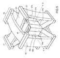
figure 5 : une vue en perspective d'un deuxième exemple de cardan flexible compact selon un deuxième mode de réalisation de l'invention ; -
figure 6 : un exemple d'application du cardan à l'orientation d'un réflecteur d'une antenne, selon l'invention. - L'exemple de cardan 5 représenté sur les
figures 1a à 1d est creux le long d'un axe Z longitudinal et central. Il comporte deux pivots creux 10, 11 à lames flexibles 12, 17, 18, 19 à double étage disposés orthogonalement l'un par rapport à l'autre. Chaque pivot creux 10, 11 s'étend selon un plan contenant l'axe longitudinal Z et orthogonal à l'axe de rotation X, respectivement Y, dudit pivot, les axes de rotation X, Y de chaque pivot étant perpendiculaires entre eux et perpendiculaires à l'axe longitudinal Z. Les trois axes X, Y, Z du cardan se coupent en un point de rotation situé au centre du cardan. De préférence, les deux pivots sont réalisés en une seule pièce monobloc. Alternativement, les deux pivots 10, 11 peuvent être constitués de deux pièces séparées reliées fixement entre elles. - Sur les exemples de réalisation représentés sur les
figures 1 a à 1 d, les deux pivots sont reliés entre eux par l'intermédiaire de deux pièces mécaniques de liaison, respectivement supérieure 50a et inférieure 50b, chaque pièce mécanique de liaison 50a, 50b étant rigide et ayant un axe longitudinal central creux coïncidant avec l'axe Z. Chaque pièce mécanique de liaison 50a, 50b peut par exemple, comme représenté sur lesfigures 1a et1b , avoir une forme de croix comportant un axe longitudinal central creux et quatre bras radiaux rigides disposés angulairement autour de l'axe longitudinal central ou comme représenté sur lafigure 1d , avoir une forme de pavé ayant un axe longitudinal central creux, le pavé pouvant par exemple être cylindrique ou parallélépipédique. Dans un mode de réalisation préférentiel, les deux pivots 10, 11 et les deux pièces mécaniques de liaison 50a, 50b, de forme pavé, sont réalisés dans une seule pièce monobloc. - Selon le premier mode de réalisation de l'invention, comme représenté sur la
figure 2 , chaque pivot 10, 11 est constitué d'un cadre externe annulaire 15, 20 s'étendant selon un plan contenant l'axe longitudinal Z et orthogonal à l'axe de rotation du pivot, d'une bague flottante interne creuse 16, 21 coaxiale au cadre externe 15, 20 et de plusieurs jeux de lames flexibles 12, 17, 18, 19 reliées au cadre externe 15, 20 et à la bague flottante interne 16, 21. Dans le cas d'un pivot à double étages, comme représenté sur lafigure 2 , le cadre externe 15, 20 de chaque pivot 10, 11 comporte, dans son épaisseur selon une direction perpendiculaire à l'axe Z, trois parties distinctes 15a, 15b, 15c, 20a, 20b, 20c disposées selon trois plans parallèles entre eux et orthogonaux à l'axe de rotation du pivot. Les trois parties distinctes du cadre externe 15, 20 sont constituées d'une première partie de cadre intermédiaire 15b, 20b contenant l'axe Z et de deux parties de cadre extérieures 15a, 15c, respectivement 20a, 20c, situées symétriquement de part et d'autre de la partie de cadre intermédiaire 15b, respectivement 20b. Chaque partie du cadre externe 15, 20 est reliée à la bague flottante interne 16, 21 par plusieurs jeux de lames flexibles 12, 17, 18, 19 réparties angulairement. A titre d'exemple non limitatif, comme représenté sur les schémas desfigures 1 a à 1 d, 2 et sur lafigure 4a , chaque pivot 10, 11 peut comporter quatre jeux 12, 17, 18, 19 de trois lames flexibles dont une première extrémité est reliée au cadre externe 15, 20 et une deuxième extrémité est reliée à la bague flottante interne 16, 21. Les deux parties de cadre extérieures 15a, 15c, respectivement 20a, 20c sont reliées à la bague flottante interne 16, 21 par l'intermédiaire d'une première et d'une deuxième lames flexibles de chacun des quatre jeux de trois lames flexibles. La partie de cadre intermédiaire 15b, 20b est reliée à la bague flottante 16, 21 par une troisième lame flexible de chacun des quatre jeux de trois lames flexibles. Alternativement, le nombre de jeux de lames flexibles peut être différent de quatre, en particulier, comme représenté sur lafigure 4b , le nombre de jeux de lames flexibles peut être, par exemple, égal à huit. - Le cadre externe 15, 20 et la bague flottante interne 16, 21 peuvent par exemple avoir une section de forme cylindrique ou polygonale, telle que par exemple rectangulaire comme représenté sur les différentes figures. Les lames flexibles 12, 17, 18, 19 peuvent être disposées selon une direction radiale du pivot 10, 11 et converger sur l'axe longitudinal Z du cardan. Alternativement, les lames flexibles peuvent être inclinées selon une direction formant un angle d'inclinaison non nul par rapport à la direction radiale du pivot.
- Sur les exemples représentés sur les
figures 1 a à 1d, les deux pivots 10, 11 du cardan sont disposés orthogonalement l'un par rapport à l'autre, les axes de rotation X et Y des deux pivots 10, 11 étant perpendiculaires entre eux. Pour cela, les dimensions des différentes parties constituant les deux pivots sont aménagées pour que les deux pivots du cardan s'imbriquent l'un dans l'autre au niveau d'une région centrale de révolution autour de l'axe Z, les deux axes de rotation X et Y des deux pivots convergeant au centre du cardan situé sur l'axe Z. Ainsi, la bague flottante interne 21 du pivot 11 a des dimensions périphériques supérieures à celle du pivot 10 de façon que la bague flottante interne 21 du pivot 11 soit montée autour de la bague flottante 16 du pivot 10 sans qu'il y ait de contact entre les deux bagues flottantes 16, 21. Par ailleurs, le cadre externe 20 du pivot 11 comporte une partie inférieure et une partie supérieure concaves alors que le cadre externe 15 du pivot 10 comporte une partie inférieure et une partie supérieure convexes de façon que le cadre externe 15 du pivot 10 soit monté autour du cadre externe 20 du pivot 11. En outre, les deux pivots 10, 11 sont reliés orthogonalement entre eux par l'intermédiaire des deux pièces mécaniques rigides 50a, 50b, respectivement supérieure et inférieure, montées entre les parties convexes et concaves supérieures des deux pivots 10, 11 et respectivement entre les parties convexes et concaves inférieures des deux pivots 10, 11. Sur lesfigures 1 a et 1 b, les deux pièces mécaniques de liaison 50a, 50b comportent quatre bras disposés en forme de croix. Les deux bras de chaque croix, diamétralement opposés l'un par rapport à l'autre, sont fixés sur la partie de cadre intermédiaire 15b du premier pivot 10, les deux autres bras de chaque croix, diamétralement opposés l'un par rapport à l'autre, sont fixés sur la partie de cadre intermédiaire 20b du deuxième pivot 11. Sur lesfigures 1c et 1d , les deux pièces mécaniques de liaison 50a, 50b sont en forme de pavé annulaire, chaque pavé annulaire étant solidaire des deux parties de cadre intermédiaires respectives 15b, 20b du premier pivot 10, et du deuxième pivot 11. Le cardan peut alors tourner en rotation autour du point de croisement des trois axes X, Y, Z. - Le fonctionnement du cardan selon l'exemple de réalisation des
figures 1c et 1d est représenté schématiquement sur lesfigures 3a à 3d . Le deuxième pivot 11 a un axe de rotation orienté selon la direction Y et le premier pivot 10 a un axe de rotation orienté selon la direction X. Dans l'exemple représenté, il est supposé que les parties de cadre extérieures 20a, 20c du deuxième pivot 11 sont fixées, dans leur partie supérieure, à un élément à orienter, par exemple un réflecteur 60 d'une antenne comme représenté sur lafigure 6 , et que les parties de cadre extérieures 15a, 15c du premier pivot 10 sont fixées, dans leur partie inférieure, sur une structure de support, par exemple un satellite, - Sur la
figure 3a , le cardan est dans une position de repos, les trois parties du cadre 15, 20 de chaque pivot 10, 11 sont superposées selon l'axe de rotation du pivot correspondant et les lames flexibles sont au repos. - Dans la
figure 3b , la partie de cadre intermédiaire 15b du pivot 10 est actionnée en rotation d'un angle α choisi, par exemple compris entre -8° et +8°, autour de l'axe X, par exemple au moyen d'un actionneur ou d'un moteur 30. Le mouvement de rotation de la partie de cadre intermédiaire 15b est transmis, par l'intermédiaire des lames flexibles, à la bague flottante interne 16 du pivot 10 qui n'est liée à aucun autre élément et est libre de suivre le mouvement de rotation de la partie de cadre intermédiaire 15b. Le mouvement de rotation de la bague flottante interne 16 est alors transmis dans les lames flexibles liées aux deux parties de cadre extérieures 15a, 15c du pivot 10. Ces parties de cadre extérieures 15a, 15c étant fixées sur un support, elles ne bougent pas et les lames flexibles qui leurs sont reliées fléchissent. Par ailleurs, les deux parties de cadre intermédiaires 15b, 20b des deux pivots 10, 11, étant liées entre elles, par l'intermédiaire des deux pièces mécaniques de liaison 50a, 50b, la rotation de la partie de cadre intermédiaire 15b du premier pivot 10 autour de l'axe X provoque le basculement, d'un même angle α, de l'ensemble du deuxième pivot 11 autour de l'axe X. - Sur la
figure 3c , les deux parties de cadre extérieures 20a, 20c du deuxième pivot 11 sont actionnées en rotation d'un angle β choisi, par exemple compris entre -8° et +8°, autour de l'axe Y, par exemple au moyen d'un actionneur ou d'un moteur 40. Le mouvement de rotation des deux parties de cadre extérieures 20a, 20c est transmis, par l'intermédiaire des lames flexibles, à la bague flottante interne 21 du deuxième pivot 11 qui n'est liée à aucun autre élément et est libre de suivre le mouvement de rotation des deux parties de cadre extérieures 20a, 20c. Le mouvement de rotation de la bague flottante 21 est alors transmis dans les lames flexibles liées à la partie de cadre intermédiaire 20b du deuxième pivot 11. Cette partie de cadre intermédiaire 20b étant fixée à la partie de cadre intermédiaire 15b du premier pivot 10 par les deux pièces mécaniques de liaison 50a, 50b, et le premier pivot 10 ne bougeant pas, la partie de cadre intermédiaire 20b ne bouge pas et les lames flexibles qui lui sont reliées fléchissent. Seules les deux parties de cadre extérieures 20a, 20c du deuxième pivot 11 subissent donc le mouvement de rotation de l'angle β, ce qui permet d'orienter l'élément fixé sur ces parties extérieures 20a, 20c par rapport à l'axe Y. - Dans la
figure 3d , les deux pivots 10, 11 sont actionnés en rotation, simultanément ou successivement, par des actionneurs respectifs 30, 40, autour de leur axe respectif X ou Y, ce qui permet d'orienter l'élément fixé sur les parties de cadre extérieures 20a, 20c du pivot 11 par rapport aux deux axes X et Y. Les mouvements de rotation combinés des deux pivots 10, 11 du cardan sont réalisés comme décrit ci-dessus pour lesfigures 3b et3c . L'élément monté sur le cardan peut alors être orienté dans n'importe quelle position choisie suivant la capacité angulaire des deux pivots du cardan. Par exemple, si les angles α et β sont compris entre -8° et +8° comme décrit ci-dessus, le cardan permet de couvrir une région située dans un cône de révolution ayant une ouverture angulaire comprise entre -8° et +8°. - Toutes les pièces constituant le cardan sont creuses le long de l'axe longitudinal Z du cardan. Le cardan est donc creux le long de l'axe Z ce qui permet de pouvoir aménager des câbles ou des guides d'onde à l'intérieur du cardan, le long de l'axe Z.
- La
figure 5 représente un deuxième mode de réalisation du cardan dans lequel les fonctions du cadre externe et de la bague interne de chaque pivot sont inversées. Selon ce deuxième mode de réalisation, chaque pivot 10, 11 du cardan comporte un cadre externe 15, 20 monté flottant et une bague interne 16, 21 constituée d'une partie de bague intermédiaire 16b, 21 b contenant l'axe Z et de deux parties de bague extérieures 16a, 16c situées parallèlement et symétriquement de part et d'autre de la partie de bague intermédiaire 16b. Chaque partie de la bague interne 16, 21 est reliée au cadre flottant externe 15, 20 par l'intermédiaire de plusieurs jeux de trois lames flexibles. Les deux parties de bague extérieures 16a, 16c du pivot 10 sont respectivement solidaires des deux parties de bague extérieures 21a, 21 c du pivot 11 et constituent des liaisons rigides communes liant les deux pivots 10, 11 entre eux. De préférence, les quatre parties de bague extérieures 16a, 16c, 21a, 21c des deux pivots forment un ensemble monobloc commun aux deux pivots 10, 11. - Sur la
figure 5 , le pivot 11, imbriqué dans le pivot 10, a un axe de rotation orienté selon la direction Y et le pivot 10, monté autour du pivot 11, a un axe de rotation orienté selon la direction X. - Dans cet exemple , il est supposé que la partie de bague intermédiaire 21 b du pivot 11 est fixée, dans la partie supérieure du cardan, à un élément à orienter, par exemple un réflecteur 60 d'une antenne comme représenté sur la
figure 6 , et que la partie de bague intermédiaire 15b du pivot 10 est fixée, dans la partie inférieure du cardan, sur une structure de support, par exemple un satellite. - Pour réaliser une rotation de l'élément à orienter autour de l'axe Y , la partie intermédiaire 21b de la bague interne 21 du pivot 11 est actionnée en rotation d'un angle choisi par rapport aux parties extérieures solidaires 16a, 16c, 21a, 21 c des deux bagues internes des deux pivots 10, 11. Le mouvement de rotation de la partie de bague intermédiaire 21b du pivot 11 est transmis, par l'intermédiaire des lames flexibles, au cadre flottant externe 20 du pivot 11 qui n'est lié à aucun autre élément et est libre de suivre le mouvement de rotation transmis par la partie de bague intermédiaire 21 b. Le mouvement de rotation du cadre flottant 20 est alors transmis dans les lames flexibles liées aux parties de bague extérieures solidaires 16a, 16c, 21 a, 21c du pivot 11 et du pivot 10.
- Pour réaliser une rotation de l'élément à orienter autour de l'axe X, les parties de bague extérieures solidaires 16a, 16c, 21a, 21c du pivot 11 et du pivot 10 sont actionnées en rotation d'un angle choisi par rapport à la partie de bague intermédiaire 15b du pivot 10 qui reste fixe. Le mouvement de rotation des parties de bague extérieures solidaires 16a, 16c, 21a, 21c est transmis, par l'intermédiaire des lames flexibles, au cadre flottant externe 15 du pivot 10 qui n'est lié à aucun autre élément et est libre de suivre le mouvement de rotation des parties de bague extérieures solidaires 16a, 16c, 21a, 21c. Le mouvement de rotation du cadre flottant externe 15 est alors transmis au reste du cardan.
Claims (8)
- Cardan flexible compact, comportant un axe longitudinal central Z creux, deux pivots creux (10, 11) montés orthogonalement l'un par rapport à l'autre et aptes à pivoter respectivement autour d'un axe de rotation X, Y, les trois axes X, Y, Z étant orthogonaux entre eux et se coupant en un point de rotation situé au centre du cardan, chaque pivot (10, 11) comportant un cadre externe annulaire (15, 20) s'étendant selon un plan contenant l'axe longitudinal central Z et orthogonal à l'axe de rotation X, respectivement Y, du pivot, une bague interne creuse (16, 21) coaxiale au cadre externe et plusieurs jeux de lames flexibles (12, 17, 18, 19) reliées au cadre externe (15, 20) et à la bague interne (16, 21), et les deux pivots (10, 11) étant reliés entre eux par des pièces de liaison rigides (50a, 50b, 16a, 16c, 21 a, 21 c).
- Cardan selon la revendication 1, caractérisé en ce que les deux pivots (10, 11) et les pièces de liaison (50a, 50b, 16a, 16c, 21 a, 21 c) sont réalisés dans une pièce monobloc.
- Cardan selon l'une des revendications 1 ou 2, caractérisé en ce que la bague interne (16, 21) de chaque pivot est montée flottante et en ce que le cadre externe (15, 20) de chaque pivot est constitué d'une première partie de cadre intermédiaire (15b, 20b) contenant l'axe Z et de deux parties de cadre extérieures (15a, 15c), respectivement (20a, 20c), situées parallèlement et de part et d'autre de la partie de cadre intermédiaire (15b, 20b), et en ce que les deux pièces de liaison (50a, 50b) ont un axe longitudinal central creux coïncidant avec l'axe Z et sont reliées aux parties de cadre intermédiaires (15b, 20b) de chaque pivot (10, 11).
- Cardan selon la revendication 3, caractérisé en ce qu'il comporte deux pièces mécaniques de liaison (50a, 50b), en ce que chaque pièce mécanique de liaison (50a, 50b) comporte quatre bras espacés angulairement et disposés en forme de croix, en ce que deux premiers bras de chaque croix, sont diamétralement opposés l'un par rapport à l'autre et fixés sur la partie de cadre intermédiaire (15b) du premier pivot (10), et en ce que deux seconds bras de chaque croix sont diamétralement opposés l'un par rapport à l'autre et fixés sur la partie de cadre intermédiaire (20b) du deuxième pivot (11).
- Cardan selon la revendication 3, caractérisé en ce qu'il comporte deux pièces mécaniques de liaison (50a, 50b) et en ce que chaque pièce mécanique de liaison (50a, 50b) a une forme de pavé annulaire, chaque pavé annulaire étant solidaire des deux parties de cadre intermédiaires respectives (15b, 20b) du premier pivot (10) et du deuxième pivot (11).
- Cardan selon l'une des revendications 1 ou 2, caractérisé en ce que le cadre externe (15, 20) de chaque pivot est monté flottant, en ce que la bague interne (16, 21) de chaque pivot est constituée d'une partie de bague intermédiaire (16b, 21 b) contenant l'axe Z et de deux parties de bague extérieures (16a, 16c, 21 a, 21 c) situées parallèlement et de part et d'autre de la partie de bague intermédiaire (16b, 21 b), et en ce que les deux parties de bague extérieures (16a, 16c) du pivot (10) sont respectivement solidaires des deux parties de bague extérieures (21a, 21c) du pivot (11) et lient d'une manière rigide les deux pivots (10, 11) entre eux.
- Cardan selon la revendication 6, caractérisé en ce que les quatre parties de bague extérieures (16a, 16c, 21a, 21c) des deux pivots forment un ensemble monobloc commun aux deux pivots (10, 11).
- Engin spatial comportant au moins un cardan selon l'une des revendications précédentes.
Applications Claiming Priority (2)
| Application Number | Priority Date | Filing Date | Title |
|---|---|---|---|
| FR1004156A FR2966534B1 (fr) | 2010-10-22 | 2010-10-22 | Cardan flexible compact et engin spatial comportant un tel cardan. |
| PCT/EP2011/067836 WO2012052337A1 (fr) | 2010-10-22 | 2011-10-12 | Cardan flexible compact et engin spatial comportant un tel cardan |
Publications (2)
| Publication Number | Publication Date |
|---|---|
| EP2630379A1 EP2630379A1 (fr) | 2013-08-28 |
| EP2630379B1 true EP2630379B1 (fr) | 2014-11-26 |
Family
ID=43973774
Family Applications (1)
| Application Number | Title | Priority Date | Filing Date |
|---|---|---|---|
| EP11767736.9A Not-in-force EP2630379B1 (fr) | 2010-10-22 | 2011-10-12 | Cardan flexible compact et engin spatial comportant un tel cardan |
Country Status (7)
| Country | Link |
|---|---|
| US (1) | US9212692B2 (fr) |
| EP (1) | EP2630379B1 (fr) |
| JP (1) | JP6044000B2 (fr) |
| CN (1) | CN103261711B (fr) |
| ES (1) | ES2527784T3 (fr) |
| FR (1) | FR2966534B1 (fr) |
| WO (1) | WO2012052337A1 (fr) |
Families Citing this family (16)
| Publication number | Priority date | Publication date | Assignee | Title |
|---|---|---|---|---|
| US10197215B2 (en) | 2014-05-25 | 2019-02-05 | Satixfy Israel Ltd. | Integral dual gimbal device |
| CN105299401A (zh) * | 2015-11-25 | 2016-02-03 | 武汉科技大学 | 一种用于多自由度位姿调整平台的万向铰节及其装配方法 |
| FR3049319B1 (fr) * | 2016-03-22 | 2018-03-16 | Airbus Operations | Cardan a structure simplifiee |
| US10414510B2 (en) | 2016-12-30 | 2019-09-17 | Safran Landing Systems Canada Inc. | Landing gear with threadless cardan joint |
| DE102017115050B3 (de) | 2017-07-05 | 2018-03-29 | Physik Instrumente (Pi) Gmbh & Co. Kg | Gelenk |
| EP3476748B1 (fr) * | 2017-10-24 | 2020-07-15 | CSEM Centre Suisse d'Electronique et de Microtechnique SA - Recherche et Développement | Mécanisme pivot à éléments flexibles |
| CN108150778A (zh) * | 2017-11-22 | 2018-06-12 | 西安电子科技大学 | 一种三自由度复合铰链 |
| CN110492229B (zh) * | 2019-08-30 | 2021-03-09 | 湖北三江航天险峰电子信息有限公司 | 一种多脊振子天线的紧固装置及紧固方法 |
| CN110657168B (zh) * | 2019-09-18 | 2021-09-03 | 西安工业大学 | 一种可应用于精密气浮转台的柔性联轴器 |
| US11566662B2 (en) * | 2019-10-25 | 2023-01-31 | Raytheon Company | Multi-axis flexure |
| JP7781051B2 (ja) * | 2020-03-13 | 2025-12-05 | 住友重機械工業株式会社 | ギヤモータ |
| CN111853481B (zh) * | 2020-08-14 | 2022-04-05 | 西安应用光学研究所 | 一种多自由度柔性支撑结构及光电稳瞄转塔万向架 |
| CN112145544B (zh) * | 2020-09-29 | 2023-02-21 | 重庆大学 | 串联结构的固定旋转中心多轴全柔性铰链 |
| US12560198B2 (en) * | 2020-11-19 | 2026-02-24 | Lawrence Livermore National Security, Llc | System and method for multi-DOF cross-pivot flexure bearing with enhanced range and enhanced load capacity |
| CN112727638B (zh) * | 2020-12-29 | 2024-07-26 | 北京中科宇航技术有限公司 | 一种用于液体火箭发动机的榫卯式机架 |
| US11635107B1 (en) | 2021-04-22 | 2023-04-25 | United States Of America As Represented By The Administrator Of The National Aeronautics And Space | Multi-link spherical joint with collocated centers of rotation |
Family Cites Families (13)
| Publication number | Priority date | Publication date | Assignee | Title |
|---|---|---|---|---|
| US19150A (en) * | 1858-01-19 | Gas-tube joint | ||
| US2950079A (en) * | 1956-06-04 | 1960-08-23 | North American Aviation Inc | Three axis flexure pivot |
| DE2653427C3 (de) * | 1976-11-24 | 1979-05-03 | Anschuetz & Co Gmbh, 2300 Kiel | Federgelenk zur schwenkbaren Verbindung zweier Körper miteinander u. Verfahren zur Herstellung des Gelenks |
| JPS5842641B2 (ja) * | 1979-08-22 | 1983-09-21 | 富士通株式会社 | アンテナ取り付け架台 |
| US4878393A (en) * | 1988-05-27 | 1989-11-07 | Oprea Duta | Dextrous spherical robot wrist |
| US4932806A (en) * | 1989-03-21 | 1990-06-12 | The United States Of America As Represented By The Administrator Of The National Aeronautics And Space Administration | Compliant joint |
| DE4010041A1 (de) * | 1990-03-29 | 1991-10-02 | Erno Raumfahrttechnik Gmbh | Spiel- und reibungsfreies universalgelenk |
| JPH0571553A (ja) * | 1991-09-10 | 1993-03-23 | Koyo Seiko Co Ltd | 等速自在継手 |
| DE19636100A1 (de) * | 1996-09-05 | 1998-03-12 | Fraunhofer Ges Forschung | Hexapod-Bearbeitungszentrum |
| DE10239966B3 (de) * | 2002-08-30 | 2004-06-09 | Integrated Electronic Systems !Sys Consulting Gmbh | Kunststoffgelenk und Verfahren zu seiner Herstellung |
| US7140969B2 (en) * | 2003-08-22 | 2006-11-28 | American Axle & Manufacturing, Inc. | Overmolded yoke assembly |
| US20070241244A1 (en) * | 2006-04-18 | 2007-10-18 | X-Ether, Inc. | Method and apparatus for eliminating keyhole problems in an X-Y gimbal assembly |
| US8016509B2 (en) * | 2007-05-04 | 2011-09-13 | Zhong Gao | Robotic joint |
-
2010
- 2010-10-22 FR FR1004156A patent/FR2966534B1/fr not_active Expired - Fee Related
-
2011
- 2011-10-12 US US13/880,937 patent/US9212692B2/en not_active Expired - Fee Related
- 2011-10-12 ES ES11767736.9T patent/ES2527784T3/es active Active
- 2011-10-12 EP EP11767736.9A patent/EP2630379B1/fr not_active Not-in-force
- 2011-10-12 WO PCT/EP2011/067836 patent/WO2012052337A1/fr not_active Ceased
- 2011-10-12 JP JP2013534257A patent/JP6044000B2/ja not_active Expired - Fee Related
- 2011-10-12 CN CN201180059596.7A patent/CN103261711B/zh not_active Expired - Fee Related
Also Published As
| Publication number | Publication date |
|---|---|
| FR2966534A1 (fr) | 2012-04-27 |
| CN103261711A (zh) | 2013-08-21 |
| JP6044000B2 (ja) | 2016-12-14 |
| FR2966534B1 (fr) | 2012-12-21 |
| CN103261711B (zh) | 2016-05-18 |
| EP2630379A1 (fr) | 2013-08-28 |
| ES2527784T3 (es) | 2015-01-30 |
| WO2012052337A1 (fr) | 2012-04-26 |
| US20140147193A1 (en) | 2014-05-29 |
| JP2013545942A (ja) | 2013-12-26 |
| US9212692B2 (en) | 2015-12-15 |
Similar Documents
| Publication | Publication Date | Title |
|---|---|---|
| EP2630379B1 (fr) | Cardan flexible compact et engin spatial comportant un tel cardan | |
| EP2256039B1 (fr) | Pivot traversant à éléments flexibles et engin spatial comportant un tel pivot | |
| EP1676776B1 (fr) | Dispositif de support d'éléments d'un équipement spatial, à lames flexibles déployables | |
| EP2503641B1 (fr) | Système d'actionnement pour réflecteur d'antenne à surface réfléchissante déformable | |
| CA2356722C (fr) | Dispositif d'orientation et systeme d'orientation embarque | |
| WO2011089354A1 (fr) | Reducteur de vitesse et mecanisme de transmission comprenant un tel reducteur pour piloter un aeronef | |
| EP3144228A1 (fr) | Actionneur gyroscopique a double guidage cardan, element de suspension et element de butee | |
| EP1964778B1 (fr) | Pivot traversant à lames | |
| EP3947158B1 (fr) | Dispositif de déploiement et de pointage d'un équipement porté par un engin spatial | |
| EP3045396B1 (fr) | Ensemble de pointage d'un instrument | |
| EP3259188B1 (fr) | Satellite artificiel | |
| EP0761996A2 (fr) | Articulation à centre de rotation et montages d'application de celle-ci | |
| EP4061727B1 (fr) | Dispositif d'orientation d'une charge selon deux axes de rotation orthogonaux | |
| EP3959141B1 (fr) | Structure déployable de grande dimension | |
| EP1377863A1 (fr) | Dispositif de montage et de correction de la position d'un miroir s'etendant dans l'ombre du miroir et systeme optique equipe de ce dispositif | |
| FR2821984A1 (fr) | Monture multiaxes a moteurs deportes et a tourelle omnidirectionnelle | |
| WO2013102668A1 (fr) | Ensemble d'un mât télescopique et d'un dispositif de support d'un équipement de véhicule sous-marin | |
| EP0455543B1 (fr) | Dispositif de pointage d'un réflecteur d'antenne | |
| FR2956488A1 (fr) | Systeme d'actionnement pour elements mobiles a mouvements relatifs compenses dynamiquement et opposes | |
| FR2972859A1 (fr) | Dispositif de commutation de reflecteurs pour une antenne a faisceau commutable |
Legal Events
| Date | Code | Title | Description |
|---|---|---|---|
| PUAI | Public reference made under article 153(3) epc to a published international application that has entered the european phase |
Free format text: ORIGINAL CODE: 0009012 |
|
| 17P | Request for examination filed |
Effective date: 20130417 |
|
| AK | Designated contracting states |
Kind code of ref document: A1 Designated state(s): AL AT BE BG CH CY CZ DE DK EE ES FI FR GB GR HR HU IE IS IT LI LT LU LV MC MK MT NL NO PL PT RO RS SE SI SK SM TR |
|
| DAX | Request for extension of the european patent (deleted) | ||
| GRAP | Despatch of communication of intention to grant a patent |
Free format text: ORIGINAL CODE: EPIDOSNIGR1 |
|
| RIC1 | Information provided on ipc code assigned before grant |
Ipc: F16C 11/12 20060101ALI20140715BHEP Ipc: B64G 1/66 20060101ALI20140715BHEP Ipc: F16C 11/06 20060101AFI20140715BHEP Ipc: H01Q 1/28 20060101ALI20140715BHEP Ipc: F16M 11/12 20060101ALI20140715BHEP Ipc: H01Q 1/12 20060101ALI20140715BHEP |
|
| INTG | Intention to grant announced |
Effective date: 20140731 |
|
| GRAS | Grant fee paid |
Free format text: ORIGINAL CODE: EPIDOSNIGR3 |
|
| GRAA | (expected) grant |
Free format text: ORIGINAL CODE: 0009210 |
|
| AK | Designated contracting states |
Kind code of ref document: B1 Designated state(s): AL AT BE BG CH CY CZ DE DK EE ES FI FR GB GR HR HU IE IS IT LI LT LU LV MC MK MT NL NO PL PT RO RS SE SI SK SM TR |
|
| REG | Reference to a national code |
Ref country code: GB Ref legal event code: FG4D Free format text: NOT ENGLISH |
|
| REG | Reference to a national code |
Ref country code: CH Ref legal event code: EP |
|
| REG | Reference to a national code |
Ref country code: AT Ref legal event code: REF Ref document number: 698387 Country of ref document: AT Kind code of ref document: T Effective date: 20141215 |
|
| REG | Reference to a national code |
Ref country code: IE Ref legal event code: FG4D Free format text: LANGUAGE OF EP DOCUMENT: FRENCH |
|
| REG | Reference to a national code |
Ref country code: CH Ref legal event code: NV Representative=s name: SERVOPATENT GMBH, CH |
|
| REG | Reference to a national code |
Ref country code: DE Ref legal event code: R096 Ref document number: 602011011768 Country of ref document: DE Effective date: 20150108 |
|
| REG | Reference to a national code |
Ref country code: ES Ref legal event code: FG2A Ref document number: 2527784 Country of ref document: ES Kind code of ref document: T3 Effective date: 20150130 |
|
| REG | Reference to a national code |
Ref country code: NL Ref legal event code: T3 |
|
| REG | Reference to a national code |
Ref country code: SE Ref legal event code: TRGR |
|
| REG | Reference to a national code |
Ref country code: LT Ref legal event code: MG4D |
|
| PG25 | Lapsed in a contracting state [announced via postgrant information from national office to epo] |
Ref country code: FI Free format text: LAPSE BECAUSE OF FAILURE TO SUBMIT A TRANSLATION OF THE DESCRIPTION OR TO PAY THE FEE WITHIN THE PRESCRIBED TIME-LIMIT Effective date: 20141126 Ref country code: IS Free format text: LAPSE BECAUSE OF FAILURE TO SUBMIT A TRANSLATION OF THE DESCRIPTION OR TO PAY THE FEE WITHIN THE PRESCRIBED TIME-LIMIT Effective date: 20150326 Ref country code: LT Free format text: LAPSE BECAUSE OF FAILURE TO SUBMIT A TRANSLATION OF THE DESCRIPTION OR TO PAY THE FEE WITHIN THE PRESCRIBED TIME-LIMIT Effective date: 20141126 Ref country code: NO Free format text: LAPSE BECAUSE OF FAILURE TO SUBMIT A TRANSLATION OF THE DESCRIPTION OR TO PAY THE FEE WITHIN THE PRESCRIBED TIME-LIMIT Effective date: 20150226 Ref country code: PT Free format text: LAPSE BECAUSE OF FAILURE TO SUBMIT A TRANSLATION OF THE DESCRIPTION OR TO PAY THE FEE WITHIN THE PRESCRIBED TIME-LIMIT Effective date: 20150326 |
|
| PG25 | Lapsed in a contracting state [announced via postgrant information from national office to epo] |
Ref country code: LV Free format text: LAPSE BECAUSE OF FAILURE TO SUBMIT A TRANSLATION OF THE DESCRIPTION OR TO PAY THE FEE WITHIN THE PRESCRIBED TIME-LIMIT Effective date: 20141126 Ref country code: GR Free format text: LAPSE BECAUSE OF FAILURE TO SUBMIT A TRANSLATION OF THE DESCRIPTION OR TO PAY THE FEE WITHIN THE PRESCRIBED TIME-LIMIT Effective date: 20150227 Ref country code: CY Free format text: LAPSE BECAUSE OF FAILURE TO SUBMIT A TRANSLATION OF THE DESCRIPTION OR TO PAY THE FEE WITHIN THE PRESCRIBED TIME-LIMIT Effective date: 20141126 Ref country code: RS Free format text: LAPSE BECAUSE OF FAILURE TO SUBMIT A TRANSLATION OF THE DESCRIPTION OR TO PAY THE FEE WITHIN THE PRESCRIBED TIME-LIMIT Effective date: 20141126 Ref country code: HR Free format text: LAPSE BECAUSE OF FAILURE TO SUBMIT A TRANSLATION OF THE DESCRIPTION OR TO PAY THE FEE WITHIN THE PRESCRIBED TIME-LIMIT Effective date: 20141126 |
|
| PG25 | Lapsed in a contracting state [announced via postgrant information from national office to epo] |
Ref country code: DK Free format text: LAPSE BECAUSE OF FAILURE TO SUBMIT A TRANSLATION OF THE DESCRIPTION OR TO PAY THE FEE WITHIN THE PRESCRIBED TIME-LIMIT Effective date: 20141126 Ref country code: SK Free format text: LAPSE BECAUSE OF FAILURE TO SUBMIT A TRANSLATION OF THE DESCRIPTION OR TO PAY THE FEE WITHIN THE PRESCRIBED TIME-LIMIT Effective date: 20141126 Ref country code: RO Free format text: LAPSE BECAUSE OF FAILURE TO SUBMIT A TRANSLATION OF THE DESCRIPTION OR TO PAY THE FEE WITHIN THE PRESCRIBED TIME-LIMIT Effective date: 20141126 Ref country code: EE Free format text: LAPSE BECAUSE OF FAILURE TO SUBMIT A TRANSLATION OF THE DESCRIPTION OR TO PAY THE FEE WITHIN THE PRESCRIBED TIME-LIMIT Effective date: 20141126 Ref country code: CZ Free format text: LAPSE BECAUSE OF FAILURE TO SUBMIT A TRANSLATION OF THE DESCRIPTION OR TO PAY THE FEE WITHIN THE PRESCRIBED TIME-LIMIT Effective date: 20141126 |
|
| REG | Reference to a national code |
Ref country code: DE Ref legal event code: R097 Ref document number: 602011011768 Country of ref document: DE |
|
| PG25 | Lapsed in a contracting state [announced via postgrant information from national office to epo] |
Ref country code: PL Free format text: LAPSE BECAUSE OF FAILURE TO SUBMIT A TRANSLATION OF THE DESCRIPTION OR TO PAY THE FEE WITHIN THE PRESCRIBED TIME-LIMIT Effective date: 20141126 |
|
| PLBE | No opposition filed within time limit |
Free format text: ORIGINAL CODE: 0009261 |
|
| STAA | Information on the status of an ep patent application or granted ep patent |
Free format text: STATUS: NO OPPOSITION FILED WITHIN TIME LIMIT |
|
| 26N | No opposition filed |
Effective date: 20150827 |
|
| PG25 | Lapsed in a contracting state [announced via postgrant information from national office to epo] |
Ref country code: SI Free format text: LAPSE BECAUSE OF FAILURE TO SUBMIT A TRANSLATION OF THE DESCRIPTION OR TO PAY THE FEE WITHIN THE PRESCRIBED TIME-LIMIT Effective date: 20141126 |
|
| PG25 | Lapsed in a contracting state [announced via postgrant information from national office to epo] |
Ref country code: LU Free format text: LAPSE BECAUSE OF FAILURE TO SUBMIT A TRANSLATION OF THE DESCRIPTION OR TO PAY THE FEE WITHIN THE PRESCRIBED TIME-LIMIT Effective date: 20151012 |
|
| PG25 | Lapsed in a contracting state [announced via postgrant information from national office to epo] |
Ref country code: MC Free format text: LAPSE BECAUSE OF FAILURE TO SUBMIT A TRANSLATION OF THE DESCRIPTION OR TO PAY THE FEE WITHIN THE PRESCRIBED TIME-LIMIT Effective date: 20141126 |
|
| REG | Reference to a national code |
Ref country code: AT Ref legal event code: UEP Ref document number: 698387 Country of ref document: AT Kind code of ref document: T Effective date: 20141126 |
|
| REG | Reference to a national code |
Ref country code: IE Ref legal event code: MM4A |
|
| REG | Reference to a national code |
Ref country code: FR Ref legal event code: PLFP Year of fee payment: 6 |
|
| PG25 | Lapsed in a contracting state [announced via postgrant information from national office to epo] |
Ref country code: IE Free format text: LAPSE BECAUSE OF NON-PAYMENT OF DUE FEES Effective date: 20151012 |
|
| PGFP | Annual fee paid to national office [announced via postgrant information from national office to epo] |
Ref country code: GB Payment date: 20160928 Year of fee payment: 6 |
|
| PGFP | Annual fee paid to national office [announced via postgrant information from national office to epo] |
Ref country code: FR Payment date: 20160928 Year of fee payment: 6 |
|
| PGFP | Annual fee paid to national office [announced via postgrant information from national office to epo] |
Ref country code: ES Payment date: 20160927 Year of fee payment: 6 |
|
| PGFP | Annual fee paid to national office [announced via postgrant information from national office to epo] |
Ref country code: NL Payment date: 20161010 Year of fee payment: 6 Ref country code: DE Payment date: 20161004 Year of fee payment: 6 Ref country code: CH Payment date: 20161013 Year of fee payment: 6 |
|
| PGFP | Annual fee paid to national office [announced via postgrant information from national office to epo] |
Ref country code: SE Payment date: 20161011 Year of fee payment: 6 Ref country code: IT Payment date: 20161024 Year of fee payment: 6 Ref country code: AT Payment date: 20160928 Year of fee payment: 6 |
|
| PG25 | Lapsed in a contracting state [announced via postgrant information from national office to epo] |
Ref country code: SM Free format text: LAPSE BECAUSE OF FAILURE TO SUBMIT A TRANSLATION OF THE DESCRIPTION OR TO PAY THE FEE WITHIN THE PRESCRIBED TIME-LIMIT Effective date: 20141126 Ref country code: HU Free format text: LAPSE BECAUSE OF FAILURE TO SUBMIT A TRANSLATION OF THE DESCRIPTION OR TO PAY THE FEE WITHIN THE PRESCRIBED TIME-LIMIT; INVALID AB INITIO Effective date: 20111012 Ref country code: BG Free format text: LAPSE BECAUSE OF FAILURE TO SUBMIT A TRANSLATION OF THE DESCRIPTION OR TO PAY THE FEE WITHIN THE PRESCRIBED TIME-LIMIT Effective date: 20141126 |
|
| PG25 | Lapsed in a contracting state [announced via postgrant information from national office to epo] |
Ref country code: BE Free format text: LAPSE BECAUSE OF NON-PAYMENT OF DUE FEES Effective date: 20151031 |
|
| PG25 | Lapsed in a contracting state [announced via postgrant information from national office to epo] |
Ref country code: MT Free format text: LAPSE BECAUSE OF FAILURE TO SUBMIT A TRANSLATION OF THE DESCRIPTION OR TO PAY THE FEE WITHIN THE PRESCRIBED TIME-LIMIT Effective date: 20141126 |
|
| REG | Reference to a national code |
Ref country code: DE Ref legal event code: R119 Ref document number: 602011011768 Country of ref document: DE |
|
| REG | Reference to a national code |
Ref country code: SE Ref legal event code: EUG |
|
| REG | Reference to a national code |
Ref country code: CH Ref legal event code: PL |
|
| REG | Reference to a national code |
Ref country code: NL Ref legal event code: MM Effective date: 20171101 |
|
| REG | Reference to a national code |
Ref country code: AT Ref legal event code: MM01 Ref document number: 698387 Country of ref document: AT Kind code of ref document: T Effective date: 20171012 |
|
| GBPC | Gb: european patent ceased through non-payment of renewal fee |
Effective date: 20171012 |
|
| PG25 | Lapsed in a contracting state [announced via postgrant information from national office to epo] |
Ref country code: TR Free format text: LAPSE BECAUSE OF FAILURE TO SUBMIT A TRANSLATION OF THE DESCRIPTION OR TO PAY THE FEE WITHIN THE PRESCRIBED TIME-LIMIT Effective date: 20141126 Ref country code: MK Free format text: LAPSE BECAUSE OF FAILURE TO SUBMIT A TRANSLATION OF THE DESCRIPTION OR TO PAY THE FEE WITHIN THE PRESCRIBED TIME-LIMIT Effective date: 20141126 |
|
| REG | Reference to a national code |
Ref country code: FR Ref legal event code: ST Effective date: 20180629 |
|
| PG25 | Lapsed in a contracting state [announced via postgrant information from national office to epo] |
Ref country code: DE Free format text: LAPSE BECAUSE OF NON-PAYMENT OF DUE FEES Effective date: 20180501 Ref country code: LI Free format text: LAPSE BECAUSE OF NON-PAYMENT OF DUE FEES Effective date: 20171031 Ref country code: GB Free format text: LAPSE BECAUSE OF NON-PAYMENT OF DUE FEES Effective date: 20171012 Ref country code: NL Free format text: LAPSE BECAUSE OF NON-PAYMENT OF DUE FEES Effective date: 20171101 Ref country code: CH Free format text: LAPSE BECAUSE OF NON-PAYMENT OF DUE FEES Effective date: 20171031 |
|
| PG25 | Lapsed in a contracting state [announced via postgrant information from national office to epo] |
Ref country code: FR Free format text: LAPSE BECAUSE OF NON-PAYMENT OF DUE FEES Effective date: 20171031 Ref country code: AT Free format text: LAPSE BECAUSE OF NON-PAYMENT OF DUE FEES Effective date: 20171012 Ref country code: SE Free format text: LAPSE BECAUSE OF NON-PAYMENT OF DUE FEES Effective date: 20171013 |
|
| PG25 | Lapsed in a contracting state [announced via postgrant information from national office to epo] |
Ref country code: AL Free format text: LAPSE BECAUSE OF FAILURE TO SUBMIT A TRANSLATION OF THE DESCRIPTION OR TO PAY THE FEE WITHIN THE PRESCRIBED TIME-LIMIT Effective date: 20141126 Ref country code: IT Free format text: LAPSE BECAUSE OF NON-PAYMENT OF DUE FEES Effective date: 20171012 |
|
| REG | Reference to a national code |
Ref country code: ES Ref legal event code: FD2A Effective date: 20181221 |
|
| PG25 | Lapsed in a contracting state [announced via postgrant information from national office to epo] |
Ref country code: ES Free format text: LAPSE BECAUSE OF NON-PAYMENT OF DUE FEES Effective date: 20171013 |