EP2630452B1 - Nmr flow metering using velocity selection and remote detection - Google Patents
Nmr flow metering using velocity selection and remote detection Download PDFInfo
- Publication number
- EP2630452B1 EP2630452B1 EP11834879.6A EP11834879A EP2630452B1 EP 2630452 B1 EP2630452 B1 EP 2630452B1 EP 11834879 A EP11834879 A EP 11834879A EP 2630452 B1 EP2630452 B1 EP 2630452B1
- Authority
- EP
- European Patent Office
- Prior art keywords
- coil
- fluid
- nuclei
- pulse
- polarization
- Prior art date
- Legal status (The legal status is an assumption and is not a legal conclusion. Google has not performed a legal analysis and makes no representation as to the accuracy of the status listed.)
- Active
Links
Images



Classifications
-
- G—PHYSICS
- G01—MEASURING; TESTING
- G01N—INVESTIGATING OR ANALYSING MATERIALS BY DETERMINING THEIR CHEMICAL OR PHYSICAL PROPERTIES
- G01N24/00—Investigating or analyzing materials by the use of nuclear magnetic resonance, electron paramagnetic resonance or other spin effects
- G01N24/08—Investigating or analyzing materials by the use of nuclear magnetic resonance, electron paramagnetic resonance or other spin effects by using nuclear magnetic resonance
- G01N24/081—Making measurements of geologic samples, e.g. measurements of moisture, pH, porosity, permeability, tortuosity or viscosity
-
- G—PHYSICS
- G01—MEASURING; TESTING
- G01F—MEASURING VOLUME, VOLUME FLOW, MASS FLOW OR LIQUID LEVEL; METERING BY VOLUME
- G01F1/00—Measuring the volume flow or mass flow of fluid or fluent solid material wherein the fluid passes through a meter in a continuous flow
- G01F1/704—Measuring the volume flow or mass flow of fluid or fluent solid material wherein the fluid passes through a meter in a continuous flow using marked regions or existing inhomogeneities within the fluid stream, e.g. statistically occurring variations in a fluid parameter
- G01F1/708—Measuring the time taken to traverse a fixed distance
- G01F1/716—Measuring the time taken to traverse a fixed distance using electron paramagnetic resonance [EPR] or nuclear magnetic resonance [NMR]
-
- G—PHYSICS
- G01—MEASURING; TESTING
- G01F—MEASURING VOLUME, VOLUME FLOW, MASS FLOW OR LIQUID LEVEL; METERING BY VOLUME
- G01F1/00—Measuring the volume flow or mass flow of fluid or fluent solid material wherein the fluid passes through a meter in a continuous flow
- G01F1/74—Devices for measuring flow of a fluid or flow of a fluent solid material in suspension in another fluid
-
- G—PHYSICS
- G01—MEASURING; TESTING
- G01N—INVESTIGATING OR ANALYSING MATERIALS BY DETERMINING THEIR CHEMICAL OR PHYSICAL PROPERTIES
- G01N24/00—Investigating or analyzing materials by the use of nuclear magnetic resonance, electron paramagnetic resonance or other spin effects
- G01N24/08—Investigating or analyzing materials by the use of nuclear magnetic resonance, electron paramagnetic resonance or other spin effects by using nuclear magnetic resonance
- G01N24/082—Measurement of solid, liquid or gas content
-
- G—PHYSICS
- G01—MEASURING; TESTING
- G01R—MEASURING ELECTRIC VARIABLES; MEASURING MAGNETIC VARIABLES
- G01R33/00—Arrangements or instruments for measuring magnetic variables
- G01R33/20—Arrangements or instruments for measuring magnetic variables involving magnetic resonance
- G01R33/44—Arrangements or instruments for measuring magnetic variables involving magnetic resonance using nuclear magnetic resonance [NMR]
- G01R33/445—MR involving a non-standard magnetic field B0, e.g. of low magnitude as in the earth's magnetic field or in nanoTesla spectroscopy, comprising a polarizing magnetic field for pre-polarisation, B0 with a temporal variation of its magnitude or direction such as field cycling of B0 or rotation of the direction of B0, or spatially inhomogeneous B0 like in fringe-field MR or in stray-field imaging
Definitions
- Multiphase fluid flows are common in pipes used in the transport of hydrocarbons for the petroleum industry.
- the current disclosure is directed to a method of using time of flight measurements to select a portion of the fluid that flows at a certain velocity.
- the velocity selection is accomplished by NMR spin-echo method.
- Difference in spin-lattice relaxation time T 1 and spin-spin relaxation time T2 for different phases are used to differentiate the signal contribution from the different phases, thus making it possible to estimate the flow rate for each individual phase.
- the apparatus comprises several polarizing magnets for fluid polarization and several NMR or EMR flow sensors which are aligned along a pipeline.
- the polarizing magnets generate a static magnetic field that is imposed on a multi-component flow.
- the linear movement of the flow generates a multi-exponential gain of magnetization along the pipeline.
- One embodiment of the disclosure is a method of estimating a flow rate of a phase of a fluid having a plurality of components.
- the method includes: polarizing nuclei of the fluid by applying a magnetic field over a plurality of non-identical polarization lengths, wherein a number of the polarization lengths is equal to or greater than a number of the components; selecting a flow velocity and measuring, for the selected flow velocity, a magnetization of the polarized nuclei for each of the plurality of polarization lengths; estimating a relative fraction of each of the plurality of components corresponding to the selected velocity based on the plurality of measured magnetizations, wherein measuring the magnetization of the polarized nuclei comprises pulsing a first coil with a tipping pulse, pulsing a second coil with a refocusing pulse, and measuring an echo resulting from the refocusing pulse with a third coil, wherein a time interval between the tipping pulse and the refocusing pulse used for measuring the echo is defined by
- the apparatus includes: a pre-polarization section configured to polarize nuclei of the fluid by applying a magnetic field over a plurality of non-identical polarization lengths, wherein a number of the polarization lengths is equal to or greater than a number of the components; a coil arrangement configured to measure, for a selected flow velocity of the fluid, a magnetization of the polarized nuclei for each of the plurality of polarization lengths, wherein the coil arrangement comprises a first coil, a second coil, and a third coil; a circuitry configured to measure, for the selected flow velocity, the magnetization of the polarized nuclei for each of the plurality of polarization lengths by pulsing the polarized nuclei with a tipping pulse from the first coil, pulsing the polarized nuclei with a refocusing pulse from the second coil, and measuring an amplitude of
- Another embodiment of the disclosure is a method of estimating a flow rate of a phase of a fluid having a plurality of components.
- the method includes: using a magnet for polarizing nuclei of the fluid flowing over a selected distance; pulsing the polarized nuclei with a tipping pulse with a first coil, a refocusing pulse with a second coil at a first distance from the first coil, a refocusing pulse with a third coil at a second distance from the first coil, and measuring an echo signal for each of the plurality of distances for a selected flow velocity, wherein a time interval between the tipping pulse and the refocusing pulse used for measuring the echo is defined by the selected velocity and a distance between the first coil and the second coil; estimating a relative fraction of each of the plurality of components corresponding to the selected velocity based on the measured echo signals.
- the apparatus includes: a magnet configured to polarize nuclei of the fluid flowing over a selected distance; a first coil, a second coil at a first distance from the first coil, a third coil at a second distance from the first coil, and at least one additional coil configured to measure an echo signal for each of the plurality of distances for a selected flow velocity; circuitry configured to pulse the polarized nuclei with a tipping pulse from the first coil, pulse the polarized nuclei with a refocusing pulse from the second coil and the third coil, and measure each echo signal resulting from the refocusing pulse using the second coil and third coil, wherein a time interval between the tipping pulse and the refocusing pulse used for measuring the echo is defined by the selected velocity and a distance between the first coil and the second coil, and a processor configured to estimate a relative fraction of each of the plurality of components corresponding to the selected velocity based on the
- FIG. 1 shows an exemplary Nuclear Magnetic Resonance (NMR) flow meter device 100 for estimating a flow rate of a fluid phase using an exemplary method of the present disclosure.
- the fluid may be a multiphase fluid.
- the fluid may be a fluid flowing in a conduit for transportation of hydrocarbons.
- the exemplary NMR flow meter 100 may include a pre-polarization section 102 for polarizing nuclear spins of fluid along a selected direction, a detection section 110 for applying NMR excitation pulses to the fluid and obtaining NMR signals in response to the NMR excitation pulses from the fluid.
- the apparatus also includes a testing unit 126 for receiving the NMR response signals from the detection section 110 and performing calculations on the received NMR response signals to obtain a flow rate of a phase of the fluid.
- the pre-polarization section 102 includes a conduit 106 and a pre-polarization magnet 104 which may be exterior to the conduit 106 in one embodiment.
- the pre-polarization magnet 104 is arranged so as to provide a static magnetic field in a volume of the pre-polarization pipe section 106, generally along a direction substantially axially along the pipe section 106. As fluid passes through the static magnetic field, nuclear spins of atoms and molecules within the fluid align along the direction of the static magnetic field.
- detection section 110 is downstream of the pre-polarization section 102 and receives polarized fluid from the pre-polarization section 102.
- the detection section 110 includes a conduit 112, a detection magnet 114 which may be exterior to the detection pipe section 112 for providing a static magnetic field in a volume of the conduit 112, and a plurality of radio frequency (RF) coils 116a, 116b, 116c.
- the diameter of the conduit 112 is the same as the diameter of the conduit 106.
- the RF coil 116 encloses a volume within the conduit 112 and is arranged to provide one or more NMR excitation pulses to the fluid in the detection section 110 and to detect one or more NMR response signals from the fluid in the detection section 110.
- Testing unit 126 includes various circuitry for obtaining one or more NMR response signals from the fluid and estimating a flow rate of a phase of the fluid from the obtained NMR response signals.
- the exemplary testing unit 126 is coupled to the RF coil 116 via preamplifier 120.
- the exemplary testing unit 126 includes a transmitter 124 for providing an NMR excitation pulse to the plurality of RF coils 116a, 116b, 116c via preamplifier 120.
- the transmitter 124 provides multiple NMR excitation pulse sequences, each NMR excitation pulse sequence tuned to a selected nuclear resonance frequency.
- a first nuclear resonance frequency is that of the nuclei of H 1 atoms and a second nuclear resonance frequency is that of the nuclei of C 13 atoms.
- the exemplary testing unit 126 also includes a receiver 122 for receiving NMR response signals detected at the RF coil 116a, 116b, 116c via the preamplifier 120.
- Testing unit 126 also includes an NMR spectrometer 128 for estimating one or more parameters of the fluid from the received NMR response signals using exemplary methods of the present disclosure.
- the spectrometer 128 may include a processor 130 configured to execute instructions contained in a program stored on a suitable storage device (not shown), such as a solid-state memory, tape or hard disc for storing the one or more parameters obtained at the processor 130.
- the pre-polarization conduit 106 of FIG. 1 may include multiphase fluid flowing through a conduit 106.
- three phases may be present: water, oil and gas.
- Each phase of the fluid has a characteristic flow velocity profile.
- a fluid or fluid phase under laminar flow exhibits a velocity profile that has a flow section at the boundaries of the fluid and a fast section typically away from the boundaries.
- the fast section of the fluid passes through a pipe section before the slowest portion does.
- the speed of the fluid affects a degree of alignment of the nuclei of the fluid. Nuclear alignment occurs over a characteristic time, as described below with respect to Eqn. (1).
- the method of the present disclosure is not restricted to laminar flow and may also be used for turbulent flow as well as flow in which one phase is mixed with another phase.
- An example of this would be gas bubbles in oil, gas bubbles in water, water droplets in an oil phase as well as oil droplets in a water phase. This is in contrast to many prior art methods which are directed towards laminar flow in which each lamina consists substantially of only one phase.
- FIG. 2 illustrates the pulsing and an echo signal that can be obtained using the apparatus of FIG. 1 .
- the magnetic field in the detection section is uniform and oriented in a longitudinal direction along the conduit 112.
- a 90° tipping pulse, indicated by 203, may be applied to the first coil 116a. This 90° tipping pulse results in the nuclei being tipped by 90°. These nuclei flow near the second coil 116b where a 180° refocusing pulse may be applied.
- the coil 116c receives and echo signal denoted by 207.
- the distance between two coils is denoted by L and the time interval between the 90° pulse and the 180° pulse (and the 180° pulse and the echo) is denoted by ⁇ t.
- ⁇ t the time interval between the 90° pulse and the 180° pulse (and the 180° pulse and the echo) is denoted by ⁇ t.
- only one refocusing pulse 205 (and refocusing coil 116b and receiving coil 116c are shown).
- the echo signal shown in FIG. 2 only comes from the part of the fluid that moves with velocity L/ ⁇ t.
- the tipping pulse is not restricted to 90° and refocusing pulse is not restricted to 180°.
- the magnetic field in the pre-polarization section 100 may be produced by a switchable permanent magnet.
- a switchable permanent magnet is disclosed in US patent application serial number 11/037,488 ( US20050189945 ).
- a coil coupled with a current source and a magnetic core having residual magnetization Disclosed therein is a coil coupled with a current source and a magnetic core having residual magnetization. Switching current in the antenna coil results in magnetization reversal in the magnetic core and reversal of the magnetic field.
- the advantage of the switchable permanent magnet is the relatively low power requirement for reversing the magnetic field and altering the polarization of nuclear spins.
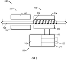
- FIG. 3 shows an alternate embodiment of the disclosure in which instead of a plurality of coils as in FIG. 1 , a single coil 316 is used.
- the axial variation of the magnitude of the axial static magnetic field is illustrated by 301.
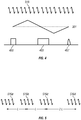
- the 90° tipping pulse is shown by 403 in FIG. 4
- the 180° refocusing pulse is shown by 405
- the echo is shown by 407.
- the external magnetic field instead of varying the static magnetic field, a pulsed field gradient may be applied in the detection section.
- FIG. 1 can be expanded.
- a fourth coil 516d is added at length 2L after coil 516c.
- coil 516c not only receives the echo signal, but also can transmit a 180° refocusing pulse and coil 516d receives the echo.
- Such a setup will increase the efficiency of data gathering.
- differentiation of the different phases of the fluid in the conduit using the apparatus described above is discussed.
- Phase differentiation may be achieved by multiple measurements with varying prepolarization length or varying flow length in the measurement region, as the one shown in FIG. 5 .
- M i is the magnetization of the i -th phase to be detected by NMR measurement
- M 0,I is the maximum prepolarization achievable, which is proportional to the amount of protons in the i -th phase
- L p is the prepolarization length
- T 1,i is the proton spin-lattice relaxation time for i -th phase.
- L p1 and L p2 are known
- v is the velocity that is selected
- T 1,1 and T 1,2 are the properties of the phases and can be characterized
- S 1 and S 2 are the measured signals, so M 0,1 and M 0,2 can be solved in the above equations.
- M 0,1 and M 0,2 are indicative of the relative fraction of the two components flowing at the selected velocity.
- a velocity v is selected 601. This defines the value of ⁇ t used with the coil separation L in the measurement section.
- a signal S 1 is measured 603 with the first pre-polarization length L p1 .
- a signal S 2 is measured 605 with the second pre-polarization length L p 2 .
- Solution of the eqn. (2) 607 then gives the relative magnetization of the two components at the selected velocity v.
- the measurement of the signal amplitude is defined by the amplitude of the echo of obtained by applying the 90° tipping pulse and a 180° refocusing pulse. This is an indication of the relative flow rates of the two components at the selected velocity.
- the velocity distribution of the two components can be obtained.
- the values of T 1,1 and T 1, 2 needed can be measured separately.
- three different pre-polarization lengths may be used.
- a velocity v is selected 701. This defines the value of ⁇ t used with a coil separation L 1 in the measurement section.
- a signal S 1 is measured 703 with the pre-polarization length L p .
- a signal S 2 is measured 705 with the same pre-polarization length L p1 and coil separation L 2 .
- Solution of the eqn. (4) 707 then gives the relative magnetization of the two components at the selected velocity v. This is an indication of the relative flow rates of the two components at the selected velocity.
- a selected response signal may be related to one or more phases of the fluid.
- a typical multiphase fluid in petroleum exploration contains a hydrocarbon phase and a water phase.
- the water phase includes primarily water molecules and therefore primarily hydrogen and oxygen atoms.
- the water phase is responsive to an 1 H NMR excitation. Since carbon atoms are generally not present in the water phase, the water phase is generally unresponsive to 13 C NMR excitation.
- the hydrocarbon phase includes molecules that are relatively rich in carbon atoms.
- the hydrocarbon phase is responsive to 13 C NMR excitations as well as to 1 H NMR excitations. Therefore, 13 C NMR response signals and H 1 NMR response signals may be used to determine water and hydrocarbon phase flow velocities and flow rates, as discussed below.
- the signal level from 13 C can be increased by using hyperpolarization.
- a suitable polarizing agent is added to the flow stream in the conduit 106.
- the polarizing agent is responsive to electron spin resonance, i.e. it contains atoms or molecules with unpaired electrons.
- the polarizing agent is added to the flow stream.
- the sample In the magnet, the sample is first magnetized to thermal equilibrium. By subjecting the sample to high frequency (HF), meeting the ESR resonance condition, and making use of the Overhauser effect (OE), the polarization of the 13 C nuclei can be enhanced beyond equilibrium by a hyperpolarization factor of up to 2600 (theoretical maximum).
- HF high frequency
- OE Overhauser effect
- the polarization of the 13 C nuclei can be enhanced beyond equilibrium by a hyperpolarization factor of up to 2600 (theoretical maximum).
- any known 13 C measurement can be executed by radiating the appropriate RF pulse sequence or by performing a CW NMR measurement at the 13 C resonance frequency. The amplitude of the received 13 C signals will be enhanced by the hyperpolarization factor.
- the phenomenon of the Nuclear Overhauser Effect is used to generate the hyperpolarization of the 13 C nuclei.
- the energy difference of the spin up and spin down states in 1 H is about 4 times of that of the energy difference of the two spin states in 13 C.
- Analogous to the OE of the previous section the 1 H transition can be saturated (instead of the unbound electrons) by radiating RF at the 1 H resonance frequency.
- the 1 H spin system can couple to the spin system of 13 C.
- the result is an increase in the population difference between spin up and spin down states of the 13 C system beyond the thermal equilibrium, i.e. the carbon nuclei are being hyperpolarized.
- the 13 C NMR is processed with enhanced signal amplitude.
- the advantage of the described method is that hydrogen is usually present in any the flow stream. In contrast to OE no extra polarization agent needs to be used.
- the polarizing agent can be polarized by optical pumping with circularly polarized light (most conveniently generated by a LASER) and making use of the Spin Induced Nuclear Overhauser Effect (SPINOE).
- the polarizing agent can be polarized in the agent chamber before being injected into the fluid sample.
- the polarizing agent is a noble gas with traces of other gases.
- the polarizing agent can be xenon with traces of a vaporized alkali metal and nitrogen.
- the discussion above is applicable to conduits in a variety of situations.
- One example would be the flow of fluids in a production well through production tubing.
- the production well may be producing hydrocarbons or may be a geothermal well in which a mixture of steam and water is produced.
- Another example is in the flow of produced hydrocarbons well to a collection point at the surface.
- the method discussed above may also be used to measure flow rate of drilling fluid. In an offshore well, the method may be used to measure the flow velocity of fluids coming up a riser.
- the processing of the data may be conveniently done on a processor.
- the processor executes a method using instructions stored on a suitable computer-readable medium product.
- the computer-readable medium may include a ROM, an EPROM, an EAROM, a flash memory, and/or an optical disk.
Landscapes
- Physics & Mathematics (AREA)
- General Physics & Mathematics (AREA)
- Fluid Mechanics (AREA)
- Life Sciences & Earth Sciences (AREA)
- High Energy & Nuclear Physics (AREA)
- Health & Medical Sciences (AREA)
- Geology (AREA)
- Geochemistry & Mineralogy (AREA)
- General Life Sciences & Earth Sciences (AREA)
- Chemical & Material Sciences (AREA)
- Analytical Chemistry (AREA)
- Biochemistry (AREA)
- General Health & Medical Sciences (AREA)
- Environmental & Geological Engineering (AREA)
- Immunology (AREA)
- Pathology (AREA)
- Engineering & Computer Science (AREA)
- Measuring Volume Flow (AREA)
Applications Claiming Priority (3)
| Application Number | Priority Date | Filing Date | Title |
|---|---|---|---|
| US12/907,707 US8729893B2 (en) | 2010-10-19 | 2010-10-19 | Nuclear magnetic resonance 1H and 13C multiphase flow measurements, estimating phase selected flow rates from velocity distributions, volume fractions, and mean velocity |
| US12/971,740 US8633689B2 (en) | 2010-10-19 | 2010-12-17 | NMR flow metering using velocity selection and remote detection |
| PCT/US2011/056065 WO2012054285A2 (en) | 2010-10-19 | 2011-10-13 | Nmr flow metering using velocity selection and remote detection |
Publications (3)
| Publication Number | Publication Date |
|---|---|
| EP2630452A2 EP2630452A2 (en) | 2013-08-28 |
| EP2630452A4 EP2630452A4 (en) | 2015-03-11 |
| EP2630452B1 true EP2630452B1 (en) | 2020-07-22 |
Family
ID=45933596
Family Applications (1)
| Application Number | Title | Priority Date | Filing Date |
|---|---|---|---|
| EP11834879.6A Active EP2630452B1 (en) | 2010-10-19 | 2011-10-13 | Nmr flow metering using velocity selection and remote detection |
Country Status (6)
| Country | Link |
|---|---|
| US (1) | US8633689B2 (da) |
| EP (1) | EP2630452B1 (da) |
| AU (1) | AU2011318360B2 (da) |
| DK (1) | DK2630452T3 (da) |
| MY (1) | MY184584A (da) |
| WO (1) | WO2012054285A2 (da) |
Families Citing this family (33)
| Publication number | Priority date | Publication date | Assignee | Title |
|---|---|---|---|---|
| US8729893B2 (en) * | 2010-10-19 | 2014-05-20 | Baker Hughes Incorporated | Nuclear magnetic resonance 1H and 13C multiphase flow measurements, estimating phase selected flow rates from velocity distributions, volume fractions, and mean velocity |
| GB2493746A (en) * | 2011-08-17 | 2013-02-20 | Schlumberger Holdings | NMR Flow meter with superconducting polariser |
| DE102012013933B4 (de) * | 2012-07-16 | 2023-12-07 | Krohne Ag | Verfahren und Vorrichtung zum Kalibrieren von kernmagnetischen Durchflussmessgeräten |
| US9448093B2 (en) * | 2012-08-15 | 2016-09-20 | Aspect Ai Ltd. | Measurement of properties of fluids using MRI |
| CN102901549B (zh) * | 2012-09-18 | 2015-01-07 | 北京航空航天大学 | 用于应变电阻式压力传感器的驱动、信号调理和采集装置 |
| AU2013254946A1 (en) * | 2012-11-14 | 2014-05-29 | Krohne Ag | Nuclear magnetic flow meter and method for operation of nuclear magnet flow meters |
| EP3011369B1 (en) | 2013-06-20 | 2019-12-11 | Aspect International (2015) Private Limited | An nmr/mri-based integrated system for analyzing and treating of a drilling mud for drilling mud recycling process and methods thereof |
| DE102014002392A1 (de) * | 2013-08-21 | 2015-02-26 | Krohne Ag | Kernmagnetisches Durchflussmessgerät und Verfahren zum Betreiben von kernmagnetischen Durchflussmessgeräten |
| US9494503B2 (en) | 2013-11-06 | 2016-11-15 | Aspect Imaging Ltd. | Inline rheology/viscosity, density, and flow rate measurement |
| DE102014010238A1 (de) * | 2014-02-20 | 2015-09-03 | Krohne Ag | Durchflussmessgerät mit einer ein tomographisches Messprinzip umsetzenden Messvorrichtung |
| EP2910906B1 (de) * | 2014-02-24 | 2020-05-27 | Krohne AG | Verfahren zum Betreiben eines kernmagnetischen Durchflussmessgeräts |
| DE102014010324B3 (de) * | 2014-05-23 | 2015-02-05 | Krohne Ag | Kernmagnetisches Durchflussmessgerät und Verfahren zum Betreiben eines kernmagnetischen Durchflussmessgeräts |
| US11300531B2 (en) | 2014-06-25 | 2022-04-12 | Aspect Ai Ltd. | Accurate water cut measurement |
| DE102015001161A1 (de) * | 2014-08-29 | 2016-03-03 | Krohne Ag | Verfahren zum Betreiben eines kernmagnetischen Durchflussmessgeräts und kernmagnetisches Durchflussmessgerät |
| EP3241042A4 (en) * | 2014-12-30 | 2018-08-15 | Halliburton Energy Services, Inc. | Combined nmr-resistivity measurement apparatus, systems, and methods |
| KR101632278B1 (ko) * | 2015-01-15 | 2016-06-21 | 한국표준과학연구원 | 저 자기장 및 극저 자기장 핵자기 공명 및 자기 공명 영상 장치 |
| US10670574B2 (en) | 2015-01-19 | 2020-06-02 | Aspect International (2015) Private Limited | NMR-based systems for crude oil enhancement and methods thereof |
| CN106053299B (zh) | 2015-04-12 | 2020-10-30 | 艾斯拜克特Ai有限公司 | 非圆形横截面管道中的流体的nmr成像 |
| CN106324010A (zh) | 2015-07-02 | 2017-01-11 | 艾斯拜克特Ai有限公司 | 使用mr设备对在管道中流动的流体的分析 |
| GB201516324D0 (en) * | 2015-09-15 | 2015-10-28 | Gill Corporate Ltd | A nuclear magnetic resonance flowmeter and a method of measuring flow using nuclear magnetic resonance |
| US10655996B2 (en) * | 2016-04-12 | 2020-05-19 | Aspect Imaging Ltd. | System and method for measuring velocity profiles |
| WO2018182884A1 (en) * | 2017-03-31 | 2018-10-04 | Halliburton Energy Services, Inc. | Downhole, real-time determination of relative permeability with nuclear magnetic resonance and formation testing measurements |
| CN109060861B (zh) * | 2018-06-20 | 2021-06-29 | 张善文 | 核磁共振流体计量仪的永磁体装置及计量方法 |
| CN108918573A (zh) * | 2018-08-23 | 2018-11-30 | 中国石油天然气股份有限公司 | 油水两相流组分含量测量方法及系统 |
| CN109254027A (zh) * | 2018-11-01 | 2019-01-22 | 西南石油大学 | 一种基于低场核磁共振的泥饼封堵评价装置及评价方法 |
| CN112683347B (zh) * | 2019-10-17 | 2022-11-04 | 中国石油天然气股份有限公司 | 流体各组分流量测量装置及方法 |
| US11933932B1 (en) * | 2020-04-06 | 2024-03-19 | Vinegar Technologies LLC | Method of estimating permeability using NMR diffusion measurements |
| US11460330B2 (en) | 2020-07-06 | 2022-10-04 | Saudi Arabian Oil Company | Reducing noise in a vortex flow meter |
| US11525723B2 (en) | 2020-08-31 | 2022-12-13 | Saudi Arabian Oil Company | Determining fluid properties |
| US11428557B2 (en) | 2020-08-31 | 2022-08-30 | Saudi Arabian Oil Company | Determining fluid properties |
| US12111273B2 (en) | 2021-12-10 | 2024-10-08 | Schlumberger Technology Corporation | Systems and methods for determining the mineralogy of drill solids |
| US12228531B1 (en) | 2022-03-29 | 2025-02-18 | Vinegar Technologies LLC | Method of determining solid and liquid components in sedimentary rocks using NMR relaxation |
| CN119355291B (zh) * | 2024-10-16 | 2025-10-10 | 中国科学院精密测量科学与技术创新研究院 | 基于超低场核磁共振的流速测量装置与方法 |
Family Cites Families (21)
| Publication number | Priority date | Publication date | Assignee | Title |
|---|---|---|---|---|
| US4536711A (en) | 1983-05-05 | 1985-08-20 | Southwest Research Institute | Method and apparatus for measuring flow in a pipe or conduit |
| US4785245A (en) | 1986-09-12 | 1988-11-15 | Engineering Measurement Company | Rapid pulse NMR cut meter |
| DE4119711A1 (de) * | 1991-06-14 | 1992-12-17 | Bayer Alwin | Verfahren und einrichtung zur bestimmung der massenstroeme einer mehrkomponentenstroemung |
| GB2291198B (en) | 1994-07-06 | 1999-01-13 | Alwin Bayer | Detection of magnetised fluid flows |
| US6046587A (en) | 1997-06-24 | 2000-04-04 | Southwest Research Institute | Measurement of flow fractions, flow velocities, and flow rates of a multiphase fluid using NMR sensing |
| GB9801622D0 (en) | 1998-01-23 | 1998-03-25 | Inst Of Food Research | Improvements in and relating to magnetic resonance imaging |
| WO2001036919A1 (en) | 1999-11-16 | 2001-05-25 | Wollin Ventures, Inc. | Magnetic resonance analyzing flow meter and flow measuring method |
| EP1340094A2 (en) | 2000-12-01 | 2003-09-03 | Protasis Corporation | Microfluidic device with multiple microcoil nmr detectors |
| US7126332B2 (en) | 2001-07-20 | 2006-10-24 | Baker Hughes Incorporated | Downhole high resolution NMR spectroscopy with polarization enhancement |
| AR037082A1 (es) | 2001-10-12 | 2004-10-20 | Back Office Service Solutions | Procedimiento para determinacion de caudal y corte de fluidos y caudalimetro sensor de corte empleado |
| US6952096B2 (en) * | 2003-09-05 | 2005-10-04 | Schlumberger Technology Corporation | Method and apparatus for determining speed and properties of flowing fluids using NMR measurements |
| EP1702284A4 (en) | 2003-12-24 | 2012-09-05 | Halliburton Energy Serv Inc | INCORRECT ESTIMATION BY USING FLUID ANALYSIS MODELS |
| KR20050066758A (ko) * | 2003-12-27 | 2005-06-30 | 삼성에스디아이 주식회사 | 그리드 기판을 구비한 전계 방출 표시장치 |
| US8432167B2 (en) | 2004-02-09 | 2013-04-30 | Baker Hughes Incorporated | Method and apparatus of using magnetic material with residual magnetization in transient electromagnetic measurement |
| US7186971B2 (en) | 2004-06-29 | 2007-03-06 | Baker Hughes Incorporated | Flowshot technique |
| AR048373A1 (es) | 2004-07-08 | 2006-04-26 | Spinlock Srl | Un dispositivo y un metodo para medir en forma directa y en tiempo real, la proporcion y el caudal de los distintos componentes que conforman un fluido complejo multicomponente , una disposicion de linea de produccion para un fluido complejo multicomponente que utiliza dicho dispositivo y un metodo |
| GB0421266D0 (en) | 2004-09-24 | 2004-10-27 | Quantx Wellbore Instrumentatio | Measurement apparatus and method |
| US7372263B2 (en) | 2005-11-23 | 2008-05-13 | Baker Hughes Incorporated | Apparatus and method for measuring cased hole fluid flow with NMR |
| AR054423A3 (es) | 2006-01-11 | 2007-06-27 | Spinlock S R L | Un aparato y metodo para medir el caudal y el corte de petroleo y agua de la produccion petrolera en tiempo y caudales reales |
| US7872474B2 (en) | 2006-11-29 | 2011-01-18 | Shell Oil Company | Magnetic resonance based apparatus and method to analyze and to measure the bi-directional flow regime in a transport or a production conduit of complex fluids, in real time and real flow-rate |
| US7459907B2 (en) | 2006-12-28 | 2008-12-02 | Schlumberger Technology Corporation | Flow measurement using NMR |
-
2010
- 2010-12-17 US US12/971,740 patent/US8633689B2/en active Active
-
2011
- 2011-10-13 WO PCT/US2011/056065 patent/WO2012054285A2/en not_active Ceased
- 2011-10-13 MY MYPI2013701036A patent/MY184584A/en unknown
- 2011-10-13 AU AU2011318360A patent/AU2011318360B2/en active Active
- 2011-10-13 DK DK11834879.6T patent/DK2630452T3/da active
- 2011-10-13 EP EP11834879.6A patent/EP2630452B1/en active Active
Non-Patent Citations (1)
| Title |
|---|
| None * |
Also Published As
| Publication number | Publication date |
|---|---|
| MY184584A (en) | 2021-04-06 |
| EP2630452A4 (en) | 2015-03-11 |
| WO2012054285A3 (en) | 2012-07-12 |
| AU2011318360A1 (en) | 2013-06-06 |
| US20120092007A1 (en) | 2012-04-19 |
| EP2630452A2 (en) | 2013-08-28 |
| AU2011318360B2 (en) | 2014-09-18 |
| US8633689B2 (en) | 2014-01-21 |
| DK2630452T3 (da) | 2020-10-19 |
| WO2012054285A2 (en) | 2012-04-26 |
Similar Documents
| Publication | Publication Date | Title |
|---|---|---|
| AU2011318360B2 (en) | NMR flow metering using velocity selection and remote detection | |
| US7852074B2 (en) | Apparatus and method for measuring cased hole fluid flow with NMR | |
| US10001395B2 (en) | Method of interpreting NMR signals to give multiphase fluid flow measurements for a gas/liquid system | |
| EP2630478B1 (en) | Multiphase flow measurement using nuclear magnetic resonance | |
| US9335195B2 (en) | Multiphase meter to provide data for production management | |
| US6268727B1 (en) | Measurement of flow fractions flow velocities and flow rates of a multiphase fluid using ESR sensing | |
| US7501819B2 (en) | Measurement apparatus and method | |
| US8248067B2 (en) | Apparatus and methods for estimating downhole fluid compositions | |
| EP0691526B1 (en) | Method and apparatus for the determination of the individual mass flow rates of a multicomponent flow | |
| US20120174684A1 (en) | Apparatus and method for real time and real flow-rate measurement of multi-phase fluids | |
| CN105091960A (zh) | 核磁式流量测量仪和用于运行核磁式流量测量仪的方法 | |
| RU2653588C2 (ru) | Ядерно-магнитный расходомер и способ эксплуатации ядерно-магнитных расходомеров | |
| Hogendoorn et al. | Magnetic Resonance Technology, A New Concept for Multiphase Flow Measurement | |
| US10393559B2 (en) | Method for operating a nuclear magnetic flowmeter and nuclear magnetic flowmeter | |
| Appel et al. | Robust multi-phase flow measurement using magnetic resonance technology | |
| US10466086B2 (en) | Method for operating a nuclear-magnetic flowmeter and nuclear magnetic flowmeter | |
| Hogendoorn et al. | Magnetic resonance technology: An innovative approach to measure multiphase flow |
Legal Events
| Date | Code | Title | Description |
|---|---|---|---|
| PUAI | Public reference made under article 153(3) epc to a published international application that has entered the european phase |
Free format text: ORIGINAL CODE: 0009012 |
|
| 17P | Request for examination filed |
Effective date: 20130516 |
|
| AK | Designated contracting states |
Kind code of ref document: A2 Designated state(s): AL AT BE BG CH CY CZ DE DK EE ES FI FR GB GR HR HU IE IS IT LI LT LU LV MC MK MT NL NO PL PT RO RS SE SI SK SM TR |
|
| DAX | Request for extension of the european patent (deleted) | ||
| RIN1 | Information on inventor provided before grant (corrected) |
Inventor name: LI, LILONG Inventor name: ONG, J., TIM Inventor name: EDWARDS, CARL, M. Inventor name: CHEN, SONGHUA |
|
| RIC1 | Information provided on ipc code assigned before grant |
Ipc: G01N 24/08 20060101AFI20150129BHEP Ipc: G01F 1/74 20060101ALI20150129BHEP Ipc: G01R 33/44 20060101ALN20150129BHEP Ipc: G01F 1/716 20060101ALI20150129BHEP |
|
| A4 | Supplementary search report drawn up and despatched |
Effective date: 20150209 |
|
| STAA | Information on the status of an ep patent application or granted ep patent |
Free format text: STATUS: EXAMINATION IS IN PROGRESS |
|
| 17Q | First examination report despatched |
Effective date: 20180621 |
|
| RIC1 | Information provided on ipc code assigned before grant |
Ipc: G01R 33/44 20060101ALN20190916BHEP Ipc: G01F 1/716 20060101ALI20190916BHEP Ipc: G01F 1/74 20060101ALI20190916BHEP Ipc: G01N 24/08 20060101AFI20190916BHEP |
|
| REG | Reference to a national code |
Ref country code: DE Ref legal event code: R079 Ref document number: 602011067915 Country of ref document: DE Free format text: PREVIOUS MAIN CLASS: G01F0001716000 Ipc: G01N0024080000 |
|
| GRAP | Despatch of communication of intention to grant a patent |
Free format text: ORIGINAL CODE: EPIDOSNIGR1 |
|
| RIC1 | Information provided on ipc code assigned before grant |
Ipc: G01N 24/08 20060101AFI20200206BHEP Ipc: G01F 1/716 20060101ALI20200206BHEP Ipc: G01R 33/44 20060101ALN20200206BHEP Ipc: G01F 1/74 20060101ALI20200206BHEP |
|
| STAA | Information on the status of an ep patent application or granted ep patent |
Free format text: STATUS: GRANT OF PATENT IS INTENDED |
|
| INTG | Intention to grant announced |
Effective date: 20200312 |
|
| RIN1 | Information on inventor provided before grant (corrected) |
Inventor name: ONG, J. TIM Inventor name: CHEN, SONGHUA Inventor name: EDWARDS, CARL M. Inventor name: LI, LILONG |
|
| RAP1 | Party data changed (applicant data changed or rights of an application transferred) |
Owner name: BAKER HUGHES, A GE COMPANY, LLC |
|
| GRAS | Grant fee paid |
Free format text: ORIGINAL CODE: EPIDOSNIGR3 |
|
| GRAA | (expected) grant |
Free format text: ORIGINAL CODE: 0009210 |
|
| STAA | Information on the status of an ep patent application or granted ep patent |
Free format text: STATUS: THE PATENT HAS BEEN GRANTED |
|
| AK | Designated contracting states |
Kind code of ref document: B1 Designated state(s): AL AT BE BG CH CY CZ DE DK EE ES FI FR GB GR HR HU IE IS IT LI LT LU LV MC MK MT NL NO PL PT RO RS SE SI SK SM TR |
|
| REG | Reference to a national code |
Ref country code: GB Ref legal event code: FG4D |
|
| REG | Reference to a national code |
Ref country code: CH Ref legal event code: EP |
|
| REG | Reference to a national code |
Ref country code: DE Ref legal event code: R096 Ref document number: 602011067915 Country of ref document: DE |
|
| REG | Reference to a national code |
Ref country code: AT Ref legal event code: REF Ref document number: 1293879 Country of ref document: AT Kind code of ref document: T Effective date: 20200815 |
|
| REG | Reference to a national code |
Ref country code: IE Ref legal event code: FG4D |
|
| REG | Reference to a national code |
Ref country code: DK Ref legal event code: T3 Effective date: 20201014 |
|
| REG | Reference to a national code |
Ref country code: NO Ref legal event code: T2 Effective date: 20200722 |
|
| REG | Reference to a national code |
Ref country code: LT Ref legal event code: MG4D |
|
| REG | Reference to a national code |
Ref country code: AT Ref legal event code: MK05 Ref document number: 1293879 Country of ref document: AT Kind code of ref document: T Effective date: 20200722 |
|
| PG25 | Lapsed in a contracting state [announced via postgrant information from national office to epo] |
Ref country code: PT Free format text: LAPSE BECAUSE OF FAILURE TO SUBMIT A TRANSLATION OF THE DESCRIPTION OR TO PAY THE FEE WITHIN THE PRESCRIBED TIME-LIMIT Effective date: 20201123 Ref country code: FI Free format text: LAPSE BECAUSE OF FAILURE TO SUBMIT A TRANSLATION OF THE DESCRIPTION OR TO PAY THE FEE WITHIN THE PRESCRIBED TIME-LIMIT Effective date: 20200722 Ref country code: LT Free format text: LAPSE BECAUSE OF FAILURE TO SUBMIT A TRANSLATION OF THE DESCRIPTION OR TO PAY THE FEE WITHIN THE PRESCRIBED TIME-LIMIT Effective date: 20200722 Ref country code: BG Free format text: LAPSE BECAUSE OF FAILURE TO SUBMIT A TRANSLATION OF THE DESCRIPTION OR TO PAY THE FEE WITHIN THE PRESCRIBED TIME-LIMIT Effective date: 20201022 Ref country code: GR Free format text: LAPSE BECAUSE OF FAILURE TO SUBMIT A TRANSLATION OF THE DESCRIPTION OR TO PAY THE FEE WITHIN THE PRESCRIBED TIME-LIMIT Effective date: 20201023 Ref country code: AT Free format text: LAPSE BECAUSE OF FAILURE TO SUBMIT A TRANSLATION OF THE DESCRIPTION OR TO PAY THE FEE WITHIN THE PRESCRIBED TIME-LIMIT Effective date: 20200722 Ref country code: ES Free format text: LAPSE BECAUSE OF FAILURE TO SUBMIT A TRANSLATION OF THE DESCRIPTION OR TO PAY THE FEE WITHIN THE PRESCRIBED TIME-LIMIT Effective date: 20200722 Ref country code: SE Free format text: LAPSE BECAUSE OF FAILURE TO SUBMIT A TRANSLATION OF THE DESCRIPTION OR TO PAY THE FEE WITHIN THE PRESCRIBED TIME-LIMIT Effective date: 20200722 Ref country code: HR Free format text: LAPSE BECAUSE OF FAILURE TO SUBMIT A TRANSLATION OF THE DESCRIPTION OR TO PAY THE FEE WITHIN THE PRESCRIBED TIME-LIMIT Effective date: 20200722 |
|
| PG25 | Lapsed in a contracting state [announced via postgrant information from national office to epo] |
Ref country code: PL Free format text: LAPSE BECAUSE OF FAILURE TO SUBMIT A TRANSLATION OF THE DESCRIPTION OR TO PAY THE FEE WITHIN THE PRESCRIBED TIME-LIMIT Effective date: 20200722 Ref country code: RS Free format text: LAPSE BECAUSE OF FAILURE TO SUBMIT A TRANSLATION OF THE DESCRIPTION OR TO PAY THE FEE WITHIN THE PRESCRIBED TIME-LIMIT Effective date: 20200722 Ref country code: LV Free format text: LAPSE BECAUSE OF FAILURE TO SUBMIT A TRANSLATION OF THE DESCRIPTION OR TO PAY THE FEE WITHIN THE PRESCRIBED TIME-LIMIT Effective date: 20200722 Ref country code: IS Free format text: LAPSE BECAUSE OF FAILURE TO SUBMIT A TRANSLATION OF THE DESCRIPTION OR TO PAY THE FEE WITHIN THE PRESCRIBED TIME-LIMIT Effective date: 20201122 |
|
| PG25 | Lapsed in a contracting state [announced via postgrant information from national office to epo] |
Ref country code: NL Free format text: LAPSE BECAUSE OF FAILURE TO SUBMIT A TRANSLATION OF THE DESCRIPTION OR TO PAY THE FEE WITHIN THE PRESCRIBED TIME-LIMIT Effective date: 20200722 |
|
| REG | Reference to a national code |
Ref country code: DE Ref legal event code: R097 Ref document number: 602011067915 Country of ref document: DE |
|
| PG25 | Lapsed in a contracting state [announced via postgrant information from national office to epo] |
Ref country code: EE Free format text: LAPSE BECAUSE OF FAILURE TO SUBMIT A TRANSLATION OF THE DESCRIPTION OR TO PAY THE FEE WITHIN THE PRESCRIBED TIME-LIMIT Effective date: 20200722 Ref country code: CZ Free format text: LAPSE BECAUSE OF FAILURE TO SUBMIT A TRANSLATION OF THE DESCRIPTION OR TO PAY THE FEE WITHIN THE PRESCRIBED TIME-LIMIT Effective date: 20200722 Ref country code: IT Free format text: LAPSE BECAUSE OF FAILURE TO SUBMIT A TRANSLATION OF THE DESCRIPTION OR TO PAY THE FEE WITHIN THE PRESCRIBED TIME-LIMIT Effective date: 20200722 Ref country code: RO Free format text: LAPSE BECAUSE OF FAILURE TO SUBMIT A TRANSLATION OF THE DESCRIPTION OR TO PAY THE FEE WITHIN THE PRESCRIBED TIME-LIMIT Effective date: 20200722 Ref country code: SM Free format text: LAPSE BECAUSE OF FAILURE TO SUBMIT A TRANSLATION OF THE DESCRIPTION OR TO PAY THE FEE WITHIN THE PRESCRIBED TIME-LIMIT Effective date: 20200722 |
|
| REG | Reference to a national code |
Ref country code: DE Ref legal event code: R119 Ref document number: 602011067915 Country of ref document: DE |
|
| PLBE | No opposition filed within time limit |
Free format text: ORIGINAL CODE: 0009261 |
|
| STAA | Information on the status of an ep patent application or granted ep patent |
Free format text: STATUS: NO OPPOSITION FILED WITHIN TIME LIMIT |
|
| PG25 | Lapsed in a contracting state [announced via postgrant information from national office to epo] |
Ref country code: AL Free format text: LAPSE BECAUSE OF FAILURE TO SUBMIT A TRANSLATION OF THE DESCRIPTION OR TO PAY THE FEE WITHIN THE PRESCRIBED TIME-LIMIT Effective date: 20200722 |
|
| REG | Reference to a national code |
Ref country code: CH Ref legal event code: PL |
|
| 26N | No opposition filed |
Effective date: 20210423 |
|
| PG25 | Lapsed in a contracting state [announced via postgrant information from national office to epo] |
Ref country code: MC Free format text: LAPSE BECAUSE OF FAILURE TO SUBMIT A TRANSLATION OF THE DESCRIPTION OR TO PAY THE FEE WITHIN THE PRESCRIBED TIME-LIMIT Effective date: 20200722 Ref country code: SK Free format text: LAPSE BECAUSE OF FAILURE TO SUBMIT A TRANSLATION OF THE DESCRIPTION OR TO PAY THE FEE WITHIN THE PRESCRIBED TIME-LIMIT Effective date: 20200722 Ref country code: LU Free format text: LAPSE BECAUSE OF NON-PAYMENT OF DUE FEES Effective date: 20201013 |
|
| REG | Reference to a national code |
Ref country code: BE Ref legal event code: MM Effective date: 20201031 |
|
| PG25 | Lapsed in a contracting state [announced via postgrant information from national office to epo] |
Ref country code: DE Free format text: LAPSE BECAUSE OF NON-PAYMENT OF DUE FEES Effective date: 20210501 Ref country code: FR Free format text: LAPSE BECAUSE OF NON-PAYMENT OF DUE FEES Effective date: 20201031 |
|
| PG25 | Lapsed in a contracting state [announced via postgrant information from national office to epo] |
Ref country code: BE Free format text: LAPSE BECAUSE OF NON-PAYMENT OF DUE FEES Effective date: 20201031 Ref country code: CH Free format text: LAPSE BECAUSE OF NON-PAYMENT OF DUE FEES Effective date: 20201031 Ref country code: SI Free format text: LAPSE BECAUSE OF FAILURE TO SUBMIT A TRANSLATION OF THE DESCRIPTION OR TO PAY THE FEE WITHIN THE PRESCRIBED TIME-LIMIT Effective date: 20200722 Ref country code: LI Free format text: LAPSE BECAUSE OF NON-PAYMENT OF DUE FEES Effective date: 20201031 |
|
| REG | Reference to a national code |
Ref country code: NL Ref legal event code: MP Effective date: 20200722 |
|
| PG25 | Lapsed in a contracting state [announced via postgrant information from national office to epo] |
Ref country code: IE Free format text: LAPSE BECAUSE OF NON-PAYMENT OF DUE FEES Effective date: 20201013 |
|
| PG25 | Lapsed in a contracting state [announced via postgrant information from national office to epo] |
Ref country code: TR Free format text: LAPSE BECAUSE OF FAILURE TO SUBMIT A TRANSLATION OF THE DESCRIPTION OR TO PAY THE FEE WITHIN THE PRESCRIBED TIME-LIMIT Effective date: 20200722 Ref country code: MT Free format text: LAPSE BECAUSE OF FAILURE TO SUBMIT A TRANSLATION OF THE DESCRIPTION OR TO PAY THE FEE WITHIN THE PRESCRIBED TIME-LIMIT Effective date: 20200722 Ref country code: CY Free format text: LAPSE BECAUSE OF FAILURE TO SUBMIT A TRANSLATION OF THE DESCRIPTION OR TO PAY THE FEE WITHIN THE PRESCRIBED TIME-LIMIT Effective date: 20200722 |
|
| PG25 | Lapsed in a contracting state [announced via postgrant information from national office to epo] |
Ref country code: MK Free format text: LAPSE BECAUSE OF FAILURE TO SUBMIT A TRANSLATION OF THE DESCRIPTION OR TO PAY THE FEE WITHIN THE PRESCRIBED TIME-LIMIT Effective date: 20200722 |
|
| P01 | Opt-out of the competence of the unified patent court (upc) registered |
Effective date: 20230526 |
|
| PGFP | Annual fee paid to national office [announced via postgrant information from national office to epo] |
Ref country code: DK Payment date: 20250923 Year of fee payment: 15 |
|
| PGFP | Annual fee paid to national office [announced via postgrant information from national office to epo] |
Ref country code: NO Payment date: 20250925 Year of fee payment: 15 |
|
| PGFP | Annual fee paid to national office [announced via postgrant information from national office to epo] |
Ref country code: GB Payment date: 20250923 Year of fee payment: 15 |