EP2630636B1 - Vorrichtung zur rücknahme von leergut, insbesondere von kunststoffflaschen und metalldosen - Google Patents
Vorrichtung zur rücknahme von leergut, insbesondere von kunststoffflaschen und metalldosen Download PDFInfo
- Publication number
- EP2630636B1 EP2630636B1 EP11808150.4A EP11808150A EP2630636B1 EP 2630636 B1 EP2630636 B1 EP 2630636B1 EP 11808150 A EP11808150 A EP 11808150A EP 2630636 B1 EP2630636 B1 EP 2630636B1
- Authority
- EP
- European Patent Office
- Prior art keywords
- channels
- input
- chute
- empties
- rear wall
- Prior art date
- Legal status (The legal status is an assumption and is not a legal conclusion. Google has not performed a legal analysis and makes no representation as to the accuracy of the status listed.)
- Active
Links
Images
Classifications
-
- B—PERFORMING OPERATIONS; TRANSPORTING
- B65—CONVEYING; PACKING; STORING; HANDLING THIN OR FILAMENTARY MATERIAL
- B65G—TRANSPORT OR STORAGE DEVICES, e.g. CONVEYORS FOR LOADING OR TIPPING, SHOP CONVEYOR SYSTEMS OR PNEUMATIC TUBE CONVEYORS
- B65G11/00—Chutes
- B65G11/02—Chutes of straight form
- B65G11/023—Chutes of straight form for articles
-
- G—PHYSICS
- G07—CHECKING-DEVICES
- G07F—COIN-FREED OR LIKE APPARATUS
- G07F7/00—Mechanisms actuated by objects other than coins to free or to actuate vending, hiring, coin or paper currency dispensing or refunding apparatus
- G07F7/06—Mechanisms actuated by objects other than coins to free or to actuate vending, hiring, coin or paper currency dispensing or refunding apparatus by returnable containers, i.e. reverse vending systems in which a user is rewarded for returning a container that serves as a token of value, e.g. bottles
- G07F7/0609—Mechanisms actuated by objects other than coins to free or to actuate vending, hiring, coin or paper currency dispensing or refunding apparatus by returnable containers, i.e. reverse vending systems in which a user is rewarded for returning a container that serves as a token of value, e.g. bottles by fluid containers, e.g. bottles, cups, gas containers
-
- Y—GENERAL TAGGING OF NEW TECHNOLOGICAL DEVELOPMENTS; GENERAL TAGGING OF CROSS-SECTIONAL TECHNOLOGIES SPANNING OVER SEVERAL SECTIONS OF THE IPC; TECHNICAL SUBJECTS COVERED BY FORMER USPC CROSS-REFERENCE ART COLLECTIONS [XRACs] AND DIGESTS
- Y02—TECHNOLOGIES OR APPLICATIONS FOR MITIGATION OR ADAPTATION AGAINST CLIMATE CHANGE
- Y02W—CLIMATE CHANGE MITIGATION TECHNOLOGIES RELATED TO WASTEWATER TREATMENT OR WASTE MANAGEMENT
- Y02W30/00—Technologies for solid waste management
- Y02W30/50—Reuse, recycling or recovery technologies
- Y02W30/62—Plastics recycling; Rubber recycling
Definitions
- the present invention relates to a device for returning empties, in particular plastic bottles and metal cans, according to the preamble of claim 1.
- Such a device is known from US 4,505,370 known.
- This device serves in particular the return of metal cans. It has a housing which umhaust facilities that serve the further treatment and optionally processing of input doses.
- the device further comprises an externally accessible input chute, which receives empties as bulk material and has a bottom inclined in the input direction.
- the input port of the input chute is covered by a grid having a suitable grid.
- the grid is formed by intersecting bars.
- a disadvantage of this solution is that empties entered as bulk material can collect on the grid, for example by jamming, and thus prevents the passage into the input chute, so that massive manual intervention is required to ensure the passage into the input chute or again manufacture.
- the EP 330 714 A1 discloses a device for returning empties, in particular plastic bottles, which has a housing which accommodates means for treating the empties entered.
- the housing has input openings that serve for the single input of plastic bottles.
- DE 295 03 823 U1 is a device for taking back empties, namely crates, described, with a housing which receives facilities for the treatment of the entered empties.
- the crates are conveyed via a roller conveyor and a conveyor belt in the interior of the device, wherein the input port is closed by a lock gate.
- Object of the present invention is to provide a generic device available, with a virtually disability-free input of empties is guaranteed as bulk material in the input chute, being prevented at the same time that can reach too large objects in the device.
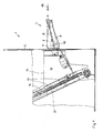
- Fig. 1 shows a portion of a housing 1 of an otherwise not shown device for taking back empties 18.
- an input chute 3 is grown from the outside.
- the housing 1 is cut free in order to make visible the internals arranged in the housing 1 in this area.
- the input tray 3 consists, with respect to the installation position, of a rear wall 4, a front wall 5 and two side walls 6 and 7 and a bottom 8, which in the input direction 19 (FIG. Fig. 1 ), ie towards the housing 1, is tilted by about 15 ° downwards.
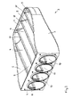
- the bottom 8 is formed of four adjacent grooves 9, which extend between the front wall 5 and the rear wall 4 and each have a same cross section over their entire length, namely that of a semicircle.
- the grooves 9 open in the rear wall 4 in each case in a circular passage opening 10 whose radius corresponds to the grooves 9.
- Adjacent channels 9 merge directly with each other to form a ridge 11.
- the cross section of the passage openings 10 and thus also of the grooves 9 is chosen so that in any case can also pass back to give empties 18 with the largest diameter unhindered.
- the input tray 3 is fixed with its rear wall 4 to the vertical wall 2 of the housing 1, e.g. by screwing.
- the housing wall 2 has in the region of the cultivation location of the input chute 3 a window, so that through the passage openings 10 therethrough a free access into the interior of the housing 1 is present.
- the bottom 8 of the input tray 3 is adjoined by a bottom of an input collecting space 13 also inclined downwards in the input direction 19, which has two side walls 14 and is open in the input direction 19.
- This open side of the input collection chamber 13 is closed by a steep conveyor 15, the upper run 16 thus effectively forms the rear wall of the input collection space 13.
- the steep conveyor 15 has roller-shaped carrier 17, which extend over the entire width of the input collection space 13.
- the drivers 17 are transverse to the conveying direction of the vertical conveyor 15 so wide that at least two pieces of empties 18 can come to rest side by side on a driver 17.
- the steep conveyor 15 promotes the collected empties 18 to further treatment stations of the device, which are not essential to the present invention and therefore not shown.
Landscapes
- Physics & Mathematics (AREA)
- General Physics & Mathematics (AREA)
- Chutes (AREA)
- Control Of Vending Devices And Auxiliary Devices For Vending Devices (AREA)
- Processing Of Solid Wastes (AREA)
- Wrapping Of Specific Fragile Articles (AREA)
- Feeding Of Articles To Conveyors (AREA)
- Control And Other Processes For Unpacking Of Materials (AREA)
Description
- Die vorliegende Erfindung betrifft eine Vorrichtung zur Rücknahme von Leergut, insbesondere von Kunststoffflaschen und Metalldosen, gemäß dem Oberbegriff des Anspruchs 1.
- Eine derartige Vorrichtung ist aus der
US 4,505,370 bekannt. Diese Vorrichtung dient insbesondere der Rücknahme von Metalldosen. Sie weist ein Gehäuse auf, welches Einrichtungen umhaust, die der weiteren Behandlung und gegebenenfalls Bearbeitung von eingegebenen Dosen dienen. Die Vorrichtung weist weiterhin eine von außen zugängliche Eingabeschütte auf, die Leergut als Schüttgut aufnimmt und einen in Eingaberichtung nach unten geneigten Boden aufweist. Um die Eingabe von zu großen Gegenständen zu verhindern bzw. zu erschweren, ist die Eingabeöffnung der Eingabeschütte durch ein Gitter mit einem geeigneten Raster abgedeckt. Das Gitter ist durch sich kreuzende Stäbe gebildet. Nachteilig an dieser Lösung ist, dass sich als Schüttgut eingegebenes Leergut auf dem Gitter, z.B. durch Verklemmen, sammeln kann und so den Durchtritt in die Eingabeschütte verhindert, so dass massive manuelle Eingriffe erforderlich sind, um den Durchlass in die Eingabeschütte zu gewährleisten bzw. wieder herzustellen. - Die
EP 330 714 A1 - In der
DE 295 03 823 U1 ist eine Vorrichtung zur Rücknahme von Leergut, und zwar von Getränkekisten, beschrieben, mit einem Gehäuse, welches Einrichtungen zur Behandlung des eingegebenen Leerguts aufnimmt. Die Getränkekisten werden über eine Rollenbahn und ein Förderband in das Innere der Vorrichtung gefördert, wobei die Eingabeöffnung durch ein Schleusentor verschließbar ist. - Aufgabe der vorliegenden Erfindung ist es, eine gattungsgemäße Vorrichtung zur Verfügung zu stellen, mit der eine nahezu behinderungsfreie Eingabe von Leergut als Schüttgut in die Eingabeschütte gewährleistet ist, wobei gleichzeitig verhindert wird, dass zu große Gegenstände in die Vorrichtung gelangen können.
- Diese Aufgabe wird erfindungsgemäß mit einer Vorrichtung zur Rücknahme von Leergut gelöst, die die Merkmale des Anspruchs 1 aufweist.
- Aufgrund der erfindungsgemäß am Boden der Eingabeschütte vorgesehenen und in Eingaberichtung verlaufenden Rinnen und der Neigung des Bodens in Eingaberichtung, richtet sich auf den Boden der Eingabeschütte aufliegendes Leergut automatisch auf die Durchlassöffnungen aus, so dass es diese ohne weiteres passieren kann. Nach rutschendes Leergut richtet sich ebenfalls auf dem Boden aus. Gegebenenfalls muss nur in einem geringen Maß bei der Ausrichtung des Leerguts manuell nachgeholfen werden.
- Weitere Vorteilhafte Ausgestaltungen der Erfindung ergeben sich aus den Unteransprüchen.
- Die Erfindung wird nachfolgend anhand eines Ausführungsbeispiels näher erläutert. In der dazugehörigen Zeichnung zeigt in schematischer Weise:
- Fig. 1
- einen Gehäuseausschnitt einer Vorrichtung zur Rücknahme von Leergut mit einer außen an das Gehäuse angesetzten Eingabeschütte, und
- Fig. 2
- eine perspektivische Darstellung der Eingabeschütte gemäß
Fig. 1 in Alleindarstellung. -
Fig. 1 zeigt einen Teil eines Gehäuses 1 einer ansonsten nicht weiter dargestellten Vorrichtung zur Rücknahme von Leergut 18. An eine lotrechte Wand 2 des Gehäuses 1 ist von außen eine Eingabeschütte 3 angebaut. Im Bereich des Anbauortes dieser Eingabeschütte 3 ist das Gehäuse 1 frei geschnitten, um die im Gehäuse 1 angeordneten Einbauten in diesem Bereich sichtbar zu machen. - Die Eingabeschütte 3 besteht, bezogen auf die Einbaulage, aus einer Rückwand 4, einer Vorderwand 5 und zwei Seitenwänden 6 und 7 sowie aus einem Boden 8, der in Eingaberichtung 19 (
Fig. 1 ), also zum Gehäuse 1 hin, um ca. 15° nach unten geneigt ist. - Der Boden 8 ist aus vier nebeneinander angeordneten Rinnen 9 gebildet, die zwischen der Vorderwand 5 und der Rückwand 4 verlaufen und auf ihrer gesamten Länge jeweils einen gleichen Querschnitt aufweisen, nämlich den eines Halbkreises. Die Rinnen 9 münden in der Rückwand 4 jeweils in eine kreisförmige Durchlassöffnung 10, deren Radius dem der Rinnen 9 entspricht. Benachbarte Rinnen 9 gehen unter Bildung eines Grates 11 unmittelbar ineinander über. Der Querschnitt der Durchlassöffnungen 10 und damit auch der Rinnen 9 ist so gewählt, dass auf jeden Fall auch zurück zu gebendes Leergut 18 mit dem größten Durchmesser ungehindert passieren kann.
- Die Eingabeschütte 3 ist mit ihrer Rückwand 4 an der lotrechten Wand 2 des Gehäuses 1 befestigt, z.B. durch Verschraubung. Die Gehäusewand 2 besitzt im Bereich des Anbauortes der Eingabeschütte 3 ein Fenster, so dass durch die Durchlassöffnungen 10 hindurch ein freier Zugang in das Innere des Gehäuses 1 vorhanden ist.
- Im Inneren des Gehäuses 1 schließt sich an den Boden 8 der Eingabeschütte 3 ein ebenfalls in Eingaberichtung 19 nach unten geneigter Boden eines Eingabesammelraums 13 an, der zwei Seitenwände 14 besitzt und in Eingaberichtung 19 offen ist. Diese offene Seite des Eingabesammelraumes 13 wird durch einen Steilförderer 15 geschlossen, dessen Obertrum 16 somit gewissermaßen die Rückwand des Eingabesammelraumes 13 bildet. Der Steilförderer 15 besitzt rollenförmige Mitnehmer 17, die sich über die gesamte Breite des Eingabesammelraumes 13 erstrecken.
- Zurück zu gebendes Leergut 18, z.B. PET-Flaschen, wird durch Ausschütten in die Eingabeschütte 3, z.B. aus einer Tasche, gewissermaßen als Schüttgut, eingegeben. Die zwischen den Rinnen 9 gebildeten Grate 11 wirken dabei als Leitkanten und sorgen dafür, dass das zunächst stochastisch in der Eingabeschütte 3 liegende Leergut 18 in Eingaberichtung 19 längs ausgerichtet wird und somit in die Rinnen 9 gelangt und unter Schwerkraftwirkung durch die Durchlassöffnungen 10 hindurch in den Eingabesammelraum 13 rutscht. Aufgrund der Neigung des Bodens des Eingabesammelraumes 13 rollt bzw. rutscht das Leergut 18 unter Schwerkraftwirkung zum Steilförderer 15 hin. Die Mitnehmer 17 des Steilförderers 15 durchlaufen den Eingabesammelraum 13, wodurch das Leergut 18, auf den Mitnehmern 7 aufliegend, mitgenommen wird. Die Mitnehmer 17 sind quer zur Förderrichtung des Steilförderers 15 so breit, dass mindestens zwei Stücke Leergut 18 nebeneinander auf einem Mitnehmer 17 zu liegen kommen können. Der Steilförderer 15 fördert das aufgenommene Leergut 18 zu weiteren Behandlungsstationen der Vorrichtung, die für die vorliegende Erfindung nicht wesentlich und daher nicht dargestellt sind.
Claims (4)
- Vorrichtung zur Rücknahme von Leergut, insbesondere von Kunststoffflaschen und Metalldosen, mit einem Gehäuse, welches Einrichtungen zur Behandlung des eingegebenen Leerguts aufnimmt, und mit einer von außen zugänglichen Eingabeschütte, die Leergut als Schüttgut aufnimmt und einen in Eingaberichtung nach unten geneigten Boden aufweist, wobei Mittel vorgesehen sind, die eine Eingabe von zu großen Gegenständen in die Vorrichtung verhindern bzw. erschweren, dadurch gekennzeichnet, dass der Boden (8) der Eingabeschütte (3) mehrere in Eingaberichtung (19) verlaufende, nebeneinander angeordnete Rinnen (9) aufweist, die jeweils in eine in die Vorrichtung führende Durchlassöffnung (10) münden, deren Querschnitt so bemessen ist, dass durch die Rinnen (9) in Eingaberichtung (19) längs ausgerichtetes Leergut (18) zwängungsfrei passieren kann.
- Vorrichtung nach Anspruch 1, dadurch gekennzeichnet, dass benachbarte Rinnen (9) unter Bildung eines Grates (11) unmittelbar ineinander übergehen.
- Vorrichtung nach Anspruch 1 oder 2, dadurch gekennzeichnet, dass die Eingabeschütte (3) in Eingaberichtung (19) gesehen, eine Vorderwand (5), eine Rückwand (4) und zwei Seitenwände (6, 7) aufweist, wobei die Rinnen (9) zwischen der Vorderwand (5) und der Rückwand (4) verlaufen und auf ihrer gesamten Länge jeweils einen gleichen Querschnitt aufweisen.
- Vorrichtung nach Anspruch 3, dadurch gekennzeichnet, dass die Rinnen (9) einen halbkreisförmigen Querschnitt aufweisen und jeweils in eine in der Rückwand (4) vorgesehene, kreisförmige Durchlassöffnung (10) münden, die den gleichen Radius wie die Rinnen (9) hat.
Applications Claiming Priority (2)
| Application Number | Priority Date | Filing Date | Title |
|---|---|---|---|
| DE201010048840 DE102010048840A1 (de) | 2010-10-18 | 2010-10-18 | Vorrichtung zur Rücknahme von Leergut, insbesondere von Kunststoffflaschen und Metalldosen |
| PCT/DE2011/001857 WO2012051999A2 (de) | 2010-10-18 | 2011-10-18 | Vorrichtung zur rücknahme von leergut, insbesondere von kunststoffflaschen und metalldosen |
Publications (2)
| Publication Number | Publication Date |
|---|---|
| EP2630636A2 EP2630636A2 (de) | 2013-08-28 |
| EP2630636B1 true EP2630636B1 (de) | 2015-07-01 |
Family
ID=45478036
Family Applications (1)
| Application Number | Title | Priority Date | Filing Date |
|---|---|---|---|
| EP11808150.4A Active EP2630636B1 (de) | 2010-10-18 | 2011-10-18 | Vorrichtung zur rücknahme von leergut, insbesondere von kunststoffflaschen und metalldosen |
Country Status (9)
| Country | Link |
|---|---|
| US (1) | US8813938B2 (de) |
| EP (1) | EP2630636B1 (de) |
| JP (1) | JP5679607B2 (de) |
| CN (1) | CN103250189A (de) |
| AU (1) | AU2011317931B2 (de) |
| CA (1) | CA2815091A1 (de) |
| DE (1) | DE102010048840A1 (de) |
| DK (1) | DK2630636T3 (de) |
| WO (1) | WO2012051999A2 (de) |
Families Citing this family (3)
| Publication number | Priority date | Publication date | Assignee | Title |
|---|---|---|---|---|
| DE102008052330A1 (de) | 2008-10-20 | 2010-06-17 | Envipco Holding N.V. | Verfahren und Transporteinrichtung zur Rücknahme von Leergut, insbesondere von Flaschen und Dosen |
| DE102011015239B3 (de) | 2011-03-26 | 2012-06-06 | Envipco Holding N.V. | Verfahren und Transporteinrichtung zur Rücknahme von Leergut |
| US9729832B2 (en) | 2014-11-14 | 2017-08-08 | Envipco Holding N.V. | Device for measuring the length and diameter of a container using structured lighting, and method of use |
Family Cites Families (16)
| Publication number | Priority date | Publication date | Assignee | Title |
|---|---|---|---|---|
| US1408497A (en) * | 1919-06-26 | 1922-03-07 | Herbert J Bragdon | Ammunition-shell-feeding machine |
| US4411351A (en) * | 1980-10-03 | 1983-10-25 | Marlene Lowder | Bottle dispensing and control system |
| US4505370A (en) | 1983-01-21 | 1985-03-19 | Reynolds Metals Company | Method for recycling cans |
| EP0330714A1 (de) * | 1988-03-02 | 1989-09-06 | Govoni Spa | Vorrichtung zur Aufbereitung und Rückverwendung von Kunststoffbehältnissen |
| US5221010A (en) * | 1991-10-25 | 1993-06-22 | Bianco James S | Apparatus for segregating bottles and cans and the like |
| US5248102A (en) * | 1992-06-15 | 1993-09-28 | Tomra Systems A/S | Device for handling empty beverage containers |
| FI92380C (fi) * | 1992-10-01 | 1994-11-10 | Halton System Oy | Menetelmä pullojen palautuksessa ja pullojen palautusjärjestelmä |
| DE29503823U1 (de) * | 1995-03-09 | 1995-06-14 | Baumüller Anlagen-Systemtechnik GmbH & Co., 90482 Nürnberg | Kundenterminal für vollautomatisches Getränketerminal |
| US5704558A (en) * | 1996-09-16 | 1998-01-06 | Can Depot, L.P. | Automated recycling center for aluminum cans |
| US5845784A (en) * | 1996-10-25 | 1998-12-08 | Satake Usa Inc. | Jam resistant channel slide for sorting machine |
| US6186308B1 (en) * | 1999-04-21 | 2001-02-13 | Can & Bottle Systems, Inc. | Reverse vending machine |
| US6315159B1 (en) * | 1999-10-22 | 2001-11-13 | Coin Acceptors, Inc. | Impact dampening system for vending machine chute |
| US6814211B2 (en) * | 2001-07-12 | 2004-11-09 | Satake Usa, Inc. | Slide for sorting machine |
| DE10347565B4 (de) | 2003-10-14 | 2006-08-10 | Wincor Nixdorf International Gmbh | Reinigungssystem für einen Rücknahmeautomaten für Leergutbehälter, Reinigungsmodul und Verfahren zum Betreiben eines Rücknahmeautomaten |
| DE202007000846U1 (de) * | 2007-01-15 | 2007-03-15 | Landre Recycling Technologies B.V. | Leergutsammeleinrichtung |
| DE102008052330A1 (de) * | 2008-10-20 | 2010-06-17 | Envipco Holding N.V. | Verfahren und Transporteinrichtung zur Rücknahme von Leergut, insbesondere von Flaschen und Dosen |
-
2010
- 2010-10-18 DE DE201010048840 patent/DE102010048840A1/de not_active Ceased
-
2011
- 2011-10-18 CN CN2011800574744A patent/CN103250189A/zh active Pending
- 2011-10-18 AU AU2011317931A patent/AU2011317931B2/en active Active
- 2011-10-18 JP JP2013538063A patent/JP5679607B2/ja active Active
- 2011-10-18 CA CA 2815091 patent/CA2815091A1/en not_active Abandoned
- 2011-10-18 EP EP11808150.4A patent/EP2630636B1/de active Active
- 2011-10-18 WO PCT/DE2011/001857 patent/WO2012051999A2/de not_active Ceased
- 2011-10-18 DK DK11808150.4T patent/DK2630636T3/da active
-
2013
- 2013-04-18 US US13/865,757 patent/US8813938B2/en active Active
Also Published As
| Publication number | Publication date |
|---|---|
| CN103250189A (zh) | 2013-08-14 |
| CA2815091A1 (en) | 2012-04-26 |
| WO2012051999A2 (de) | 2012-04-26 |
| US20130299304A1 (en) | 2013-11-14 |
| EP2630636A2 (de) | 2013-08-28 |
| AU2011317931A1 (en) | 2013-05-30 |
| DE102010048840A1 (de) | 2012-04-19 |
| JP5679607B2 (ja) | 2015-03-04 |
| JP2013544399A (ja) | 2013-12-12 |
| DK2630636T3 (da) | 2015-09-21 |
| WO2012051999A3 (de) | 2012-06-14 |
| AU2011317931B2 (en) | 2017-02-02 |
| US8813938B2 (en) | 2014-08-26 |
Similar Documents
| Publication | Publication Date | Title |
|---|---|---|
| EP1955604B1 (de) | Vorrichtung und Verfahren zum Befüllen von Behältern mit stabförmigen Produkten | |
| EP2635510A1 (de) | Transportvorrichtung zum transportieren von behältern | |
| EP3556691B1 (de) | Vereinzelungsentlader und verfahren zum entladen und vereinzeln von in einem behälter bereitgestellten packstücken | |
| EP3418227B1 (de) | Schienengebundener transportroboter und verfahren zum betrieb eines schienengebundenen transportroboters | |
| EP2630636B1 (de) | Vorrichtung zur rücknahme von leergut, insbesondere von kunststoffflaschen und metalldosen | |
| DE2701336C2 (de) | Bunkerverschluß | |
| DE10137843A1 (de) | Vorrichtung zum Sortieren und zum Weitertransport von Schüttgut | |
| EP2266442B1 (de) | Entnahmevorrichtung für Lebensmittelprodukte | |
| EP2228324A2 (de) | Vorrichtung zum Transportieren von Leergut | |
| DE4225041A1 (de) | Kommissionieranlage | |
| DE202006013956U1 (de) | Warenannahmeautomat | |
| DE102010033697A1 (de) | Kontrollstation, Vereinzelungsvorrichtung und Verfahren zum Vereinzeln von Stückgütern | |
| EP3760322B1 (de) | Dosierförderer zum fördern und dosieren eines feststoffgemisches | |
| DE10340752B4 (de) | Vorrichtung zum Transportieren und zum Vereinzeln von Holzerzeugnissen | |
| EP2691943B1 (de) | Verfahren und transporteinrichtung zur rücknahme von leergut, insbesondere von flaschen und dosen | |
| EP1577848B1 (de) | Ausgabeeinheit für Waren, insbesondere Backwaren | |
| EP2045024B1 (de) | Sortiervorrichtung für Pflanzen | |
| DE19924373C2 (de) | Hub- und Beschickungswagen | |
| DE69714839T2 (de) | Kombinatorischer wiegeapparat | |
| AT510369A2 (de) | Verfahren zur vereinzelung von stückgut | |
| DE3929656A1 (de) | Verfahren und vorrichtung zum lagern in und zum automatischen entnehmen von stueckgutsorten aus regalen in grosslagern | |
| DE19943562A1 (de) | Entpacken und Entrollieren von rondenförmigen Werkstücken, Münzen oder dgl. | |
| WO2016011565A2 (de) | Vorrichtung und verfahren zum ausrichten von losen flächengebilden | |
| EP3932817B1 (de) | Transportbehälter | |
| DE2428996A1 (de) | Vorrichtung fuer die aufnahme von silberware |
Legal Events
| Date | Code | Title | Description |
|---|---|---|---|
| PUAI | Public reference made under article 153(3) epc to a published international application that has entered the european phase |
Free format text: ORIGINAL CODE: 0009012 |
|
| 17P | Request for examination filed |
Effective date: 20130417 |
|
| AK | Designated contracting states |
Kind code of ref document: A2 Designated state(s): AL AT BE BG CH CY CZ DE DK EE ES FI FR GB GR HR HU IE IS IT LI LT LU LV MC MK MT NL NO PL PT RO RS SE SI SK SM TR |
|
| DAX | Request for extension of the european patent (deleted) | ||
| 17Q | First examination report despatched |
Effective date: 20140425 |
|
| GRAP | Despatch of communication of intention to grant a patent |
Free format text: ORIGINAL CODE: EPIDOSNIGR1 |
|
| INTG | Intention to grant announced |
Effective date: 20150210 |
|
| GRAS | Grant fee paid |
Free format text: ORIGINAL CODE: EPIDOSNIGR3 |
|
| GRAA | (expected) grant |
Free format text: ORIGINAL CODE: 0009210 |
|
| AK | Designated contracting states |
Kind code of ref document: B1 Designated state(s): AL AT BE BG CH CY CZ DE DK EE ES FI FR GB GR HR HU IE IS IT LI LT LU LV MC MK MT NL NO PL PT RO RS SE SI SK SM TR |
|
| REG | Reference to a national code |
Ref country code: GB Ref legal event code: FG4D Free format text: NOT ENGLISH |
|
| REG | Reference to a national code |
Ref country code: AT Ref legal event code: REF Ref document number: 734367 Country of ref document: AT Kind code of ref document: T Effective date: 20150715 Ref country code: CH Ref legal event code: EP |
|
| REG | Reference to a national code |
Ref country code: CH Ref legal event code: NV Representative=s name: E. BLUM AND CO. AG PATENT- UND MARKENANWAELTE , CH |
|
| REG | Reference to a national code |
Ref country code: IE Ref legal event code: FG4D Free format text: LANGUAGE OF EP DOCUMENT: GERMAN |
|
| REG | Reference to a national code |
Ref country code: DE Ref legal event code: R096 Ref document number: 502011007217 Country of ref document: DE |
|
| REG | Reference to a national code |
Ref country code: DK Ref legal event code: T3 Effective date: 20150916 |
|
| REG | Reference to a national code |
Ref country code: SE Ref legal event code: TRGR |
|
| REG | Reference to a national code |
Ref country code: NO Ref legal event code: T2 Effective date: 20150701 |
|
| REG | Reference to a national code |
Ref country code: NL Ref legal event code: FP |
|
| REG | Reference to a national code |
Ref country code: LT Ref legal event code: MG4D |
|
| PG25 | Lapsed in a contracting state [announced via postgrant information from national office to epo] |
Ref country code: LT Free format text: LAPSE BECAUSE OF FAILURE TO SUBMIT A TRANSLATION OF THE DESCRIPTION OR TO PAY THE FEE WITHIN THE PRESCRIBED TIME-LIMIT Effective date: 20150701 Ref country code: LV Free format text: LAPSE BECAUSE OF FAILURE TO SUBMIT A TRANSLATION OF THE DESCRIPTION OR TO PAY THE FEE WITHIN THE PRESCRIBED TIME-LIMIT Effective date: 20150701 Ref country code: GR Free format text: LAPSE BECAUSE OF FAILURE TO SUBMIT A TRANSLATION OF THE DESCRIPTION OR TO PAY THE FEE WITHIN THE PRESCRIBED TIME-LIMIT Effective date: 20151002 |
|
| PG25 | Lapsed in a contracting state [announced via postgrant information from national office to epo] |
Ref country code: PL Free format text: LAPSE BECAUSE OF FAILURE TO SUBMIT A TRANSLATION OF THE DESCRIPTION OR TO PAY THE FEE WITHIN THE PRESCRIBED TIME-LIMIT Effective date: 20150701 Ref country code: RS Free format text: LAPSE BECAUSE OF FAILURE TO SUBMIT A TRANSLATION OF THE DESCRIPTION OR TO PAY THE FEE WITHIN THE PRESCRIBED TIME-LIMIT Effective date: 20150701 Ref country code: PT Free format text: LAPSE BECAUSE OF FAILURE TO SUBMIT A TRANSLATION OF THE DESCRIPTION OR TO PAY THE FEE WITHIN THE PRESCRIBED TIME-LIMIT Effective date: 20151102 Ref country code: IS Free format text: LAPSE BECAUSE OF FAILURE TO SUBMIT A TRANSLATION OF THE DESCRIPTION OR TO PAY THE FEE WITHIN THE PRESCRIBED TIME-LIMIT Effective date: 20151101 Ref country code: ES Free format text: LAPSE BECAUSE OF FAILURE TO SUBMIT A TRANSLATION OF THE DESCRIPTION OR TO PAY THE FEE WITHIN THE PRESCRIBED TIME-LIMIT Effective date: 20150701 Ref country code: HR Free format text: LAPSE BECAUSE OF FAILURE TO SUBMIT A TRANSLATION OF THE DESCRIPTION OR TO PAY THE FEE WITHIN THE PRESCRIBED TIME-LIMIT Effective date: 20150701 |
|
| REG | Reference to a national code |
Ref country code: DE Ref legal event code: R097 Ref document number: 502011007217 Country of ref document: DE |
|
| PG25 | Lapsed in a contracting state [announced via postgrant information from national office to epo] |
Ref country code: SK Free format text: LAPSE BECAUSE OF FAILURE TO SUBMIT A TRANSLATION OF THE DESCRIPTION OR TO PAY THE FEE WITHIN THE PRESCRIBED TIME-LIMIT Effective date: 20150701 Ref country code: EE Free format text: LAPSE BECAUSE OF FAILURE TO SUBMIT A TRANSLATION OF THE DESCRIPTION OR TO PAY THE FEE WITHIN THE PRESCRIBED TIME-LIMIT Effective date: 20150701 Ref country code: CZ Free format text: LAPSE BECAUSE OF FAILURE TO SUBMIT A TRANSLATION OF THE DESCRIPTION OR TO PAY THE FEE WITHIN THE PRESCRIBED TIME-LIMIT Effective date: 20150701 |
|
| PLBE | No opposition filed within time limit |
Free format text: ORIGINAL CODE: 0009261 |
|
| STAA | Information on the status of an ep patent application or granted ep patent |
Free format text: STATUS: NO OPPOSITION FILED WITHIN TIME LIMIT |
|
| PG25 | Lapsed in a contracting state [announced via postgrant information from national office to epo] |
Ref country code: LU Free format text: LAPSE BECAUSE OF FAILURE TO SUBMIT A TRANSLATION OF THE DESCRIPTION OR TO PAY THE FEE WITHIN THE PRESCRIBED TIME-LIMIT Effective date: 20151018 Ref country code: RO Free format text: LAPSE BECAUSE OF FAILURE TO SUBMIT A TRANSLATION OF THE DESCRIPTION OR TO PAY THE FEE WITHIN THE PRESCRIBED TIME-LIMIT Effective date: 20150701 |
|
| 26N | No opposition filed |
Effective date: 20160404 |
|
| PG25 | Lapsed in a contracting state [announced via postgrant information from national office to epo] |
Ref country code: MC Free format text: LAPSE BECAUSE OF FAILURE TO SUBMIT A TRANSLATION OF THE DESCRIPTION OR TO PAY THE FEE WITHIN THE PRESCRIBED TIME-LIMIT Effective date: 20150701 |
|
| REG | Reference to a national code |
Ref country code: IE Ref legal event code: MM4A |
|
| PG25 | Lapsed in a contracting state [announced via postgrant information from national office to epo] |
Ref country code: SI Free format text: LAPSE BECAUSE OF FAILURE TO SUBMIT A TRANSLATION OF THE DESCRIPTION OR TO PAY THE FEE WITHIN THE PRESCRIBED TIME-LIMIT Effective date: 20150701 |
|
| REG | Reference to a national code |
Ref country code: FR Ref legal event code: PLFP Year of fee payment: 6 |
|
| PG25 | Lapsed in a contracting state [announced via postgrant information from national office to epo] |
Ref country code: IE Free format text: LAPSE BECAUSE OF NON-PAYMENT OF DUE FEES Effective date: 20151018 |
|
| PG25 | Lapsed in a contracting state [announced via postgrant information from national office to epo] |
Ref country code: SM Free format text: LAPSE BECAUSE OF FAILURE TO SUBMIT A TRANSLATION OF THE DESCRIPTION OR TO PAY THE FEE WITHIN THE PRESCRIBED TIME-LIMIT Effective date: 20150701 Ref country code: BG Free format text: LAPSE BECAUSE OF FAILURE TO SUBMIT A TRANSLATION OF THE DESCRIPTION OR TO PAY THE FEE WITHIN THE PRESCRIBED TIME-LIMIT Effective date: 20150701 Ref country code: HU Free format text: LAPSE BECAUSE OF FAILURE TO SUBMIT A TRANSLATION OF THE DESCRIPTION OR TO PAY THE FEE WITHIN THE PRESCRIBED TIME-LIMIT; INVALID AB INITIO Effective date: 20111018 |
|
| PG25 | Lapsed in a contracting state [announced via postgrant information from national office to epo] |
Ref country code: CY Free format text: LAPSE BECAUSE OF FAILURE TO SUBMIT A TRANSLATION OF THE DESCRIPTION OR TO PAY THE FEE WITHIN THE PRESCRIBED TIME-LIMIT Effective date: 20150701 |
|
| PG25 | Lapsed in a contracting state [announced via postgrant information from national office to epo] |
Ref country code: MT Free format text: LAPSE BECAUSE OF FAILURE TO SUBMIT A TRANSLATION OF THE DESCRIPTION OR TO PAY THE FEE WITHIN THE PRESCRIBED TIME-LIMIT Effective date: 20150701 |
|
| REG | Reference to a national code |
Ref country code: FR Ref legal event code: PLFP Year of fee payment: 7 |
|
| PG25 | Lapsed in a contracting state [announced via postgrant information from national office to epo] |
Ref country code: TR Free format text: LAPSE BECAUSE OF FAILURE TO SUBMIT A TRANSLATION OF THE DESCRIPTION OR TO PAY THE FEE WITHIN THE PRESCRIBED TIME-LIMIT Effective date: 20150701 Ref country code: MK Free format text: LAPSE BECAUSE OF FAILURE TO SUBMIT A TRANSLATION OF THE DESCRIPTION OR TO PAY THE FEE WITHIN THE PRESCRIBED TIME-LIMIT Effective date: 20150701 |
|
| REG | Reference to a national code |
Ref country code: FR Ref legal event code: PLFP Year of fee payment: 8 |
|
| PG25 | Lapsed in a contracting state [announced via postgrant information from national office to epo] |
Ref country code: AL Free format text: LAPSE BECAUSE OF FAILURE TO SUBMIT A TRANSLATION OF THE DESCRIPTION OR TO PAY THE FEE WITHIN THE PRESCRIBED TIME-LIMIT Effective date: 20150701 |
|
| REG | Reference to a national code |
Ref country code: CH Ref legal event code: U11 Free format text: ST27 STATUS EVENT CODE: U-0-0-U10-U11 (AS PROVIDED BY THE NATIONAL OFFICE) Effective date: 20251101 |
|
| PGFP | Annual fee paid to national office [announced via postgrant information from national office to epo] |
Ref country code: NL Payment date: 20251023 Year of fee payment: 15 |
|
| PGFP | Annual fee paid to national office [announced via postgrant information from national office to epo] |
Ref country code: DE Payment date: 20251212 Year of fee payment: 15 |
|
| PGFP | Annual fee paid to national office [announced via postgrant information from national office to epo] |
Ref country code: GB Payment date: 20251024 Year of fee payment: 15 |
|
| PGFP | Annual fee paid to national office [announced via postgrant information from national office to epo] |
Ref country code: NO Payment date: 20251022 Year of fee payment: 15 |
|
| PGFP | Annual fee paid to national office [announced via postgrant information from national office to epo] |
Ref country code: AT Payment date: 20251021 Year of fee payment: 15 |
|
| PGFP | Annual fee paid to national office [announced via postgrant information from national office to epo] |
Ref country code: FI Payment date: 20251022 Year of fee payment: 15 Ref country code: DK Payment date: 20251023 Year of fee payment: 15 Ref country code: IT Payment date: 20251031 Year of fee payment: 15 |
|
| PGFP | Annual fee paid to national office [announced via postgrant information from national office to epo] |
Ref country code: FR Payment date: 20251024 Year of fee payment: 15 |
|
| PGFP | Annual fee paid to national office [announced via postgrant information from national office to epo] |
Ref country code: BE Payment date: 20251022 Year of fee payment: 15 |
|
| PGFP | Annual fee paid to national office [announced via postgrant information from national office to epo] |
Ref country code: CH Payment date: 20251101 Year of fee payment: 15 Ref country code: SE Payment date: 20251023 Year of fee payment: 15 |