EP2631003A1 - Wärmeintegrierte Destillationsvorrichtung - Google Patents
Wärmeintegrierte Destillationsvorrichtung Download PDFInfo
- Publication number
- EP2631003A1 EP2631003A1 EP13154580.8A EP13154580A EP2631003A1 EP 2631003 A1 EP2631003 A1 EP 2631003A1 EP 13154580 A EP13154580 A EP 13154580A EP 2631003 A1 EP2631003 A1 EP 2631003A1
- Authority
- EP
- European Patent Office
- Prior art keywords
- column
- pipe
- rectifying
- stripping
- rectifying column
- Prior art date
- Legal status (The legal status is an assumption and is not a legal conclusion. Google has not performed a legal analysis and makes no representation as to the accuracy of the status listed.)
- Granted
Links
Images



Classifications
-
- B—PERFORMING OPERATIONS; TRANSPORTING
- B01—PHYSICAL OR CHEMICAL PROCESSES OR APPARATUS IN GENERAL
- B01D—SEPARATION
- B01D3/00—Distillation or related exchange processes in which liquids are contacted with gaseous media, e.g. stripping
- B01D3/14—Fractional distillation or use of a fractionation or rectification column
- B01D3/32—Other features of fractionating columns ; Constructional details of fractionating columns not provided for in groups B01D3/16 - B01D3/30
-
- B—PERFORMING OPERATIONS; TRANSPORTING
- B01—PHYSICAL OR CHEMICAL PROCESSES OR APPARATUS IN GENERAL
- B01D—SEPARATION
- B01D3/00—Distillation or related exchange processes in which liquids are contacted with gaseous media, e.g. stripping
- B01D3/007—Energy recuperation; Heat pumps
-
- B—PERFORMING OPERATIONS; TRANSPORTING
- B01—PHYSICAL OR CHEMICAL PROCESSES OR APPARATUS IN GENERAL
- B01D—SEPARATION
- B01D1/00—Evaporating
- B01D1/28—Evaporating with vapour compression
-
- B—PERFORMING OPERATIONS; TRANSPORTING
- B01—PHYSICAL OR CHEMICAL PROCESSES OR APPARATUS IN GENERAL
- B01D—SEPARATION
- B01D3/00—Distillation or related exchange processes in which liquids are contacted with gaseous media, e.g. stripping
- B01D3/14—Fractional distillation or use of a fractionation or rectification column
- B01D3/143—Fractional distillation or use of a fractionation or rectification column by two or more of a fractionation, separation or rectification step
-
- B—PERFORMING OPERATIONS; TRANSPORTING
- B01—PHYSICAL OR CHEMICAL PROCESSES OR APPARATUS IN GENERAL
- B01D—SEPARATION
- B01D3/00—Distillation or related exchange processes in which liquids are contacted with gaseous media, e.g. stripping
- B01D3/14—Fractional distillation or use of a fractionation or rectification column
- B01D3/26—Fractionating columns in which vapour and liquid flow past each other, or in which the fluid is sprayed into the vapour, or in which a two-phase mixture is passed in one direction
-
- B—PERFORMING OPERATIONS; TRANSPORTING
- B01—PHYSICAL OR CHEMICAL PROCESSES OR APPARATUS IN GENERAL
- B01D—SEPARATION
- B01D3/00—Distillation or related exchange processes in which liquids are contacted with gaseous media, e.g. stripping
- B01D3/42—Regulation; Control
- B01D3/4211—Regulation; Control of columns
- B01D3/4261—Side stream
Definitions
- the present invention relates to a distillation apparatus that carries out a distillation operation widely applied to many industrial processes, and more particularly to a heat integrated distillation apparatus.
- HIDiC heat integrated distillation column
- a basic system of the HIDiC has a structure in which a rectifying section (high-pressure unit) and a stripping section (low-pressure unit) are provided such that they are separate from each other. Operation pressure of the rectifying section is set higher than that of the stripping section so that the operation temperature of the rectifying section can be higher than that of the stripping section. This enables a reduction in the amount of heat that is supplied to a reboiler because heat transfer occurs from the rectifying section to the stripping section when there is a heat-exchange surface therebetween. Heat of the rectifying section moves to the stripping section, and hence the amount of heat that is supplied at a reboiler can be reduced. As a result, high energy saving distillation apparatus can be achieved.
- Q the heat exchanged rate between the rectifying section and the stripping section
- U an overall heat-transfer coefficient
- A a heat transfer area
- ⁇ T a temperature difference between the rectifying section and the stripping section.
- U an overall heat-transfer coefficient
- A a heat transfer area
- ⁇ T a temperature difference between the rectifying section and the stripping section.
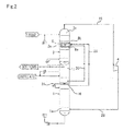
- FIG. 2 shows an example of the distillation apparatus disclosed in JP4803470B .
- the distillation apparatus includes rectifying column 1, stripping column 2 located higher than rectifying column 1, first pipe 23 for connecting column top 2c of the stripping column with column bottom 1a of the rectifying column, and compressor 4 that compresses vapor from column top 2c of the stripping column to feed the compressed vapor to column bottom 1a of the rectifying column.
- the distillation apparatus further includes liquid sump unit 2e located at a predetermined stage of stripping column 2 and configured to hold liquid that has flowed downward, heat exchanger 8 located in liquid sump unit 2e, partition plate 16 that is set in a predetermined position of rectifying column 1 and configured to apart upper stages and lower stages completely, second pipe 29 for introducing vapor below partition plate 16 to heat exchanger 8, and third pipe 30 for introducing fluids introduced through second pipe 29 to heat exchanger 8 and then discharged out of heat exchanger 8 to an upper side of partition plate 16.
- the vapor is withdrawn from rectifying column 1 through second pipe 29.
- the vapor is introduced to heat exchanger 8 in stripping column 2.
- heat can be transferred from rectifying column 1 to stripping column 2.
- High-pressure vapor in rectifying column 1 ascends through second pipe 29 to heat exchanger 8 in stripping column 2.
- a fluid partially or totally condensed from the vapor in heat exchanger 8 is accordingly pushed out from stripping column 2 to third pipe 30 outside the column.
- this configuration also necessitates no pressure-feeding means such as a pump in supplying liquid from stripping column 2 to rectifying column 1 located at a lower side in a vertical direction.
- Rectifying column 1 and stripping column 2 can be configured by using trayed sections or packed bed sections similar to those of a general distillation apparatus. Hence, the apparatus can deal with side cutting or multi-feed stream without the need for any improvement, and it is possible to easily perform maintenance of the apparatus. For the same reason, the number of stages of the rectifying column or the stripping column can be freely set, and a feed stage can be optimized.
- a heat transfer area can be freely set, and hence the heat exchanged rate can be determined without any dependence on the temperature difference between the columns.
- the apparatus of the present invention has a structure in which a degree of freedom in design is high, and hence can be easily accepted by the user side.
- Partition plate 16 that completely partitions the inside of the column to an upper side and a lower side is installed in an arbitrary stage of rectifying column 1, all of vapor ascending from below partition plate 16 is withdrawn from the column through pipe 29, and is supplied to tube-bundle-type heat exchanger 8 installed at an arbitrary stage of stripping column 2, where heat exchange is performed. Thereafter, a fluid partially or totally condensed in heat exchanger 8 flows through pipe 30 outside the column to the upper side of partition plate 16 in rectifying column 1 by gravity, and the condensed liquid flows through another pipe 31 to be movable to below partition plate 16. Such circulation of the fluids is performed.
- Such a method intend to withdraw all of the vapor in rectifying column 1 to the outside of the column, and hence adopts a complicated structure in which partition plate 16 is installed in rectifying column 1, and the condensed liquid fed onto partition plate 16 from stripping column 2 is further transferred to a lower side space of partition plate 16 through pipe 31 and control valve 17 outside the column.
- partition plate 16 is installed in rectifying column 1
- the condensed liquid fed onto partition plate 16 from stripping column 2 is further transferred to a lower side space of partition plate 16 through pipe 31 and control valve 17 outside the column.
- An object of the present invention is to achieve further energy saving and reduction of manufacturing cost in the above described distillation apparatus ( FIG. 2 ) to improve the aforementioned points.
- a heat integrated distillation apparatus includes: a rectifying column including a trayed section or a packed bed section, which is a column shell used as a rectifying section; a stripping column located above seen from the rectifying column and including a trayed section or a packed bed section, which is a column shell used as a stripping section; a first pipe for communicating a column top of the stripping column with a column bottom of the rectifying column; and a compressor installed in the first pipe and configured to compress vapor from the column top of the stripping column and then feed the compressed vapor to the column bottom of the rectifying column.
- the aspect of the present invention includes: a liquid sump unit located at a predetermined stage of the stripping column and configured to hold liquid that has flowed downward; a heat exchanger located in the liquid sump unit of the stripping column; a second pipe for introducing vapor in the rectifying column to the heat exchanger of the stripping column; and a third pipe for introducing fluids flowing out from the heat exchanger of the stripping column to the rectifying column.
- volume shrinkage generated by withdrawing a part of the vapor from the rectifying column through the second pipe, and totally condensing the vapor in heat exchanger 8 in the stripping column becomes a drive force, and a flow of the fluids from the rectifying column to the stripping column, and further from the stripping column to the rectifying column is obtained.
- no pressure-feeding means such as a pump is necessary.
- the plate which is configured for complete partition of the upper and lower stages (partition plate 16 of FIG. 2 ) is not installed in rectifying column 1. Therefore, as compared with the distillation apparatus of FIG. 2 , the pressure loss in the rectifying section can be reduced by the amount corresponding to installation of no partition wall, the pressure at the column bottom side of the rectifying column is reduced and the outlet side pressure of the compressor can be suppressed to be low. Thus, energy saving performance is enhanced. Further, the structure can be also simplified.
- the apparatus configuration which transfers heat from the rectifying column to the stripping column by using the second and third pipes and the heat exchanger as described above as compared with a distillation apparatus including no such heat transfer configuration, the amount of heat removed at a condenser attached to the column top of the rectifying column can be reduced more, and the amount of heat supplied at a reboiler attached to the column bottom of the stripping column can be reduced more. As a result, a distillation apparatus that is very high in energy efficiency can be provided.
- the rectifying column and the stripping column are configured by using trayed sections or packed bed sections similar to those of a general distillation apparatus.
- the apparatus can deal with side cutting or multi-feed stream without the need for any special improvement, and it is possible to easily perform maintenance of the apparatus.
- the number of stages of the rectifying column or the stripping column can be freely set, and a raw material feed stage can be optimized.
- a heat transfer area can be freely set, and hence the heat exchanged rate can be determined without any dependence on the temperature difference between the columns.
- a line having lower pressure than pressure in the rectifying column is connected to a downstream side of the third pipe.
- a first flow toward an inside of the rectifying column through the third pipe is switchable to a second flow branching from the third pipe toward the line.
- the apparatus of the present invention has a structure in which a degree of freedom in design is high, and hence can be easily accepted by the user side.
- a heat integrated distillation apparatus has a basic feature in which a column shell (stripping column) that is used as a stripping section extending in a vertical direction, and a column shell (rectifying column) that is used as a rectifying section extending in the vertical direction are provided separately from each other, and the stripping column is located higher than the rectifying column.
- a general distillation apparatus which is not an internally heat integrated distillation apparatus, includes a column built in a vertical direction and having a column bottom, a trayed section (or packed bed section) and a column top, wherein at a boundary of a feed location, an upper side of the trayed section (or packed bed section) is a rectifying section and a lower side is a stripping section, and is totally different from the heat integrated distillation apparatus according to the present invention.
- an arrangement described as follows is made by adding an improvement to the distillation apparatus shown in FIG. 2 that is proposed by the present applicant.
- an embodiment example of the present invention will be described by using the same reference signs for the same components as those shown in FIG. 2 .
- FIG. 3 shows an overall configuration of a heat integrated distillation apparatus according to an embodiment of the present invention.
- the heat integrated distillation apparatus according to the embodiment includes rectifying column 1 and stripping column 2 that are located higher than rectifying column 1.
- Rectifying column 1 includes column bottom 1a, trayed section (or packed bed section) 1b, and column top 1c.
- Stripping column 2 also includes column bottom 2a, trayed section (or packed bed section) 2b, and top column 2c.
- Trayed section 1b and 2b are sections where several horizontal trays are located therein.
- a tray on which vapor and liquid contact mutually is referred to as a stage.
- gas-liquid contact promotes a mass transfer.
- a gas phase having rich in components with higher volatility ascends to an upper stage, while a liquid phase having rich in components with lower volatility descends to a lower stage.
- gas-liquid contact is executed again with a new liquid phase or gas phase there for further mass transfer.
- there are components in rich with higher volatility at a higher stage of the column there are components in rich with lower volatility at a lower stage, and a distillation operation is accomplished.
- the packed section that can replace the trayed section is a section where a certain packing is installed in the empty column, and gas-liquid contact is executed on its surface.
- trayed sections 1b and 2b are shown as blank. In reality, however, the abovementioned structures are employed.
- Each of rectifying column 1 and stripping column 2 is described in detail. First, stripping column 2 is described.
- Heater 3 referred to as a reboiler is disposed outside column bottom 2a of stripping column 2, and pipe 21 is provided from a lower space part of column bottom 2a through heater 3 to an upper space part of column bottom 2a. Liquid descending through trayed section 2b (or packed bed section) of stripping column 2 accordingly stays at column bottom 2a. A part of the liquid is heated by heater 3 to become vapor, and returns to column bottom 2a. From the bottommost part of column bottom 2a, liquid in rich with lower volatility components is acquired through pipe 22.
- Column top 2c of stripping column 2 is a position for supplying feed stream.
- Column top 2c is connected, via compressor 4, to column bottom 1a of rectifying column 1 by using pipe 23.
- the feed stream is supplied at the top of column 2c of stripping column 2.
- the feed stage can be an arbitrary stage of trayed section 2b (or packed bed section). Even when there is a plurality of raw materials, the feed stage can be column top 2c of stripping column 2 and other arbitrary stages (including a stage of rectifying column 1).
- trayed section 2b (or packed bed section) includes liquid sump unit 2e at a predetermined stage.
- Liquid sump unit 2e stores a predetermined amount of liquid 10 that has flowed down onto chimney tray for sump 15, and liquid spilled from chimney tray for sump 15 drops.
- tube-bundle-type heat exchanger 8 is inserted into liquid sump unit 2e (refer to FIG. 4 ).
- Parallel tube portions 8a and 8b in the U-shaped tube of tube-bundle-type heat exchanger 8 are arranged along chimney tray for sump 15.
- Pipe 29 (refer to FIG. 3 ) for feeding fluids from rectifying column 1 to stripping column 2 is connected to upper tube portion 8b of the parallel tube portions.
- Pipe 30 (refer to FIG. 3 ) for feeding fluids from stripping column 2 to rectifying column 1 is connected to lower tube portion 8a.
- a raw material liquid descends from column top 2c of stripping column 2 through a trayed or a packed layer.
- Liquid 10 (refer to FIG. 4 ) stays at liquid sump unit 2e on chimney tray for sump 15 that is located at an arbitrary stage.
- the U-shaped tube of tube-bundle-type heat exchanger 8 is located in liquid sump unit 2e, and hence the U-shaped tube is dipped in liquid 10.
- high-temperature vapor in rectifying column 1 is introduced through pipe 29 into upper tube portion 8b of heat exchanger 8, a part of liquid 10 in contact with the outer walls of tube portions 8b and 8a, where the high-temperature vapor moves, is heated to become vapor 18 and ascends (refer to FIG.
- the high-temperature vapor introduced through pipe 29 into heat exchanger 8 is condensed and is changed into a liquid phase from a vapor phase while being moved from upper tube portion 8b to lower tube portion 8a.
- the liquid is introduced through pipe 30 outside the column to a predetermined stage of rectifying column 1 as described below (refer to FIG. 3 ).
- valve 42 installed in third pipe 30 is closed, a liquid is stored in third pipe 30 and then valve 42 is opened, vapor flows into heat exchanger 8 correspondingly to a volume of the liquid, the vapor is drastically cooled by the liquid of liquid sump unit 2e around it, and large volume shrinkage occurs.
- volume shrinkage force that draws the high-pressure vapor in rectifying column 1 into heat exchanger 8 of stripping section 2 is generated, and a flow of the vapor toward heat exchanger 8 through pipe 29 from rectifying column 1 is established.
- Liquid that is condensed from vapor in heat exchanger 8 descends into rectifying column 1 by gravity. In this manner, the fluids constantly circulate.
- no pressure-feeding means such as a pump is necessary.
- Rectifying column 1 of the present embodiment is described below.
- pipe 26 One end of pipe 26 is connected to a bottommost part of column bottom 1a of rectifying column 1, while the other end of pipe 26 is connected to pipe 27 for supplying feed materials to column top 2c of stripping column 2.
- pipe 27 For recycle the liquid staying at column bottom 1a of rectifying column 1 to column top 2c of stripping column 2 located higher than rectifying column 1, pump 6 is necessary at the midway section of pipe 26.
- Condenser 7 is equipped outside column top 1c of rectifying column 1, and pipe 28 is connected from an upper space part of column top 1c to condenser 7.
- vapor that has withdrawn from column top 1c of rectifying column 1 is cooled by the condenser 7 to become liquid, and a distillate liquid having components with higher volatility is acquired. A part of the liquid is refluxed to column top 1c.
- trayed section 1b (or packed bed section) of rectifying column 1 communicates with pipe 29 at a predetermined position, and ascending vapor at this stage is fed to upper tube portion 8b of heat exchanger 8 arranged in liquid sump unit 2e of stripping column 2 through pipe 29 extending in the vertical direction.
- Pipe 30 from a stripping column 2 penetrates through an outer wall of rectifying column 1 and is inserted into an upper stage of a stage where pipe 29 is inserted.
- the liquid condensed from vapor in heat exchanger 8 is introduced into rectifying column 1 through pipe 30. Further, when the vapor ascending in rectifying column 1 reaches column top 1c, the vapor passes through pipe 28 and is cooled in condenser 7. As a result, a distillate liquid having components with higher volatility is acquired.
- the vapor is withdrawn from rectifying column 1 through pipe 29, the vapor is introduced into heat exchanger 8 in stripping column 2, and thereby the heat in rectifying column 1 is removed and can be transferred into stripping column 2.
- a heat transfer system using pipes 29 and 30 and heat exchanger 8 as in the case of the embodiment is configured as if a side condenser is installed at an arbitrary stage of rectifying column 1 and, simultaneously, as if a side reboiler is installed at an arbitrary stage of stripping column 2.
- FIG. 3 shows only one heat transfer system.
- the number of heat transfer systems equivalent to 10 to 30% of the total number of theoretical stages can be installed.
- the number of heat transfer systems to be installed and locations of the heat exchanger and the pipes can be arbitrarily determined according to a design specification.
- the present applicant has found out that as described above, even with the configuration in which partition plate 16 is not installed in rectifying column 1 as shown in FIG. 2 , the volume shrinkage that is generated by withdrawing the vapor in rectifying column 1 to outside the column, and totally condensing the vapor in heat exchanger 8 in stripping column 2 becomes a drive force, and a flow of the fluids from rectifying column 1 to stripping column 2 and further from stripping column 2 to rectifying column 1 can be obtained.
- the pressure loss in rectifying section 1 can be reduced by the amount corresponding to installation of no partition plate 16 as shown in FIG. 2 , and pressure at an outlet side of compressor 4 can be suppressed to be low by reducing the pressure at the column bottom side of rectifying column 1.
- energy saving performance is enhanced.
- the structure can be also simplified.
- outlet 30a of pipe 30 that communicates with the inside of rectifying column 1 is brought into a state where outlet 30a is not sealed with the liquid due to pressure variation during operation of the distillation apparatus, the vapor sometimes flows into pipe 30 from rectifying column 1, and there is the fear of the flow of the fluids described above being not established.
- valve 42 that is an opening-closing mechanism which opens and closes a pipe passage is installed in pipe 30 extending from heat exchanger 8 of stripping column 2 to rectifying column 1, as shown in FIG. 3 .
- pipe 44 connected to a low pressure line (flare line 43 in the present example) having lower pressure than the pressure in rectifying column 1 is connected to an upstream side from valve 42 of pipe 30.
- Valve 45 that is an opening-closing mechanism which opens and closes a pipe passage is also installed in pipe 44.
- valve 42 When outlet 30a of pipe 30 is not sealed with the liquid, valve 42 is closed and valve 45 is opened, whereby vapor is forcefully introduced into pipe 29 from the inside of rectifying column 1 by a pressure difference between flare line 43 and rectifying column 1, and the above described flow of the fluids is regenerated.
- Opening and closing of valve 42 and valve 45 are switched in response to a state of the liquid in outlet 30a of pipe 30, and hence monitoring means 46 such as a level gauge or level indicator that can monitor presence and absence of the liquid in the pipes is desirably installed at a spot apart to an upstream side from a position of outlet 30a of pipe 30.
- monitoring means 46 detects that the liquid is absent in a site of pipe 30 where it is located
- monitoring means 46 sends a signal to opening and closing drive sections of valve 42 and valve 45 to close valve 42 and open valve 45.
- monitoring means 46 opens valve 42 and closes valve 45.
- Such a method establishes circulation of stable side heat exchange in the distillation apparatus of the example of the present invention.
- valve 42 and valve 45 are provided in the above described embodiment.
- elements that achieve the means are not limited to them.
- the element is not limited to the flare line if only it has pressure lower than the pressure in rectifying column 1.
- the method may be adopted in which in place of valve 42 and valve 45, a direction switching valve is installed in an intersection point of pipe 30 and pipe 44, and only when lack of liquid in pipe 30 is confirmed by monitoring means 46, a route is switched to only the route flowing from pipe 30 to pipe 44 with the direction switching valve. In this case, the flow of the fluids can be regenerated by forcefully introducing the vapor into pipe 29 from the inside of rectifying column 1 with only operation of one direction switching valve, and hence control becomes easy.
- the heat integrated distillation apparatus described above is configured by using the trayed column or the packed column similar to that of the general distillation apparatus. This enables side-cutting or multi-feeding without any need to improve the apparatus, and easy maintenance of the apparatus. For the same reason, freedom for setting the numbers of stages for the rectifying column and the stripping column enables optimization of feed stages. In other words, the present invention can solve problems 1) to 5) of the heat integrated distillation apparatus using the double-pipe structure represented by JP2004-16928A .
- tube-bundle-type heat exchanger 8 is used as the component of the heat transfer system that transfers heat from rectifying column 1 to stripping column 2. This enables free changing of the heat transfer area A based on a tube design of heat exchanger 8.
- the present invention can therefore solve problem 6) of the heat integrated distillation apparatus using the double-pipe structure.
- rectifying column 1 and stripping column 2 are connected to each other in the vertical direction.
- the present invention is not limited to this arrangement.
- the present invention includes an arrangement where rectifying column 1 and stripping column 2 are configured separately and independently, and stripping column 2 is located higher than rectifying column 1.
Landscapes
- Chemical & Material Sciences (AREA)
- Chemical Kinetics & Catalysis (AREA)
- Vaporization, Distillation, Condensation, Sublimation, And Cold Traps (AREA)
Applications Claiming Priority (1)
| Application Number | Priority Date | Filing Date | Title |
|---|---|---|---|
| JP2012038988A JP5923335B2 (ja) | 2012-02-24 | 2012-02-24 | 熱交換型蒸留装置 |
Publications (2)
| Publication Number | Publication Date |
|---|---|
| EP2631003A1 true EP2631003A1 (de) | 2013-08-28 |
| EP2631003B1 EP2631003B1 (de) | 2015-07-08 |
Family
ID=47715898
Family Applications (1)
| Application Number | Title | Priority Date | Filing Date |
|---|---|---|---|
| EP13154580.8A Active EP2631003B1 (de) | 2012-02-24 | 2013-02-08 | Wärmeintegrierte Destillationsvorrichtung |
Country Status (6)
| Country | Link |
|---|---|
| US (1) | US9266034B2 (de) |
| EP (1) | EP2631003B1 (de) |
| JP (1) | JP5923335B2 (de) |
| KR (1) | KR102007629B1 (de) |
| CN (1) | CN103285609B (de) |
| DK (1) | DK2631003T3 (de) |
Cited By (2)
| Publication number | Priority date | Publication date | Assignee | Title |
|---|---|---|---|---|
| EP2875850A1 (de) * | 2013-11-21 | 2015-05-27 | Toyo Engineering Corporation | Vorrichtung mit drei wärmeintegrierten Säulen zur Trennung von 1-buten |
| CN109675333A (zh) * | 2017-10-19 | 2019-04-26 | 中国石化工程建设有限公司 | 热泵驱动的苯塔分馏装置及方法 |
Families Citing this family (8)
| Publication number | Priority date | Publication date | Assignee | Title |
|---|---|---|---|---|
| US20120085126A1 (en) * | 2010-10-06 | 2012-04-12 | Exxonmobil Research And Engineering Company | Low energy distillation system and method |
| DE102015122209A1 (de) * | 2015-12-18 | 2017-02-16 | Basf Se | Kolonne zur thermischen Behandlung von fluiden Gemischen |
| JP6566876B2 (ja) * | 2016-01-26 | 2019-08-28 | 東洋エンジニアリング株式会社 | 内部熱交換型蒸留塔の熱交換量調節方法 |
| CN109107210B (zh) * | 2017-06-26 | 2023-11-14 | 河北金牛旭阳化工有限公司 | 精馏设备 |
| CN108815874A (zh) * | 2018-08-30 | 2018-11-16 | 安徽顺恒信新材料有限公司 | 一种精馏釜自流装置 |
| KR102778710B1 (ko) * | 2019-09-25 | 2025-03-07 | 주식회사 엘지화학 | 중합체 제조 장치 |
| CN112742056B (zh) * | 2019-10-31 | 2023-01-10 | 中国石油化工股份有限公司 | 一种用于三组分分离的内部能量集成的精馏装置和利用其进行精馏的方法 |
| CN112274959A (zh) * | 2020-10-24 | 2021-01-29 | 河北工业大学 | 一种多组分分离式精馏塔 |
Citations (3)
| Publication number | Priority date | Publication date | Assignee | Title |
|---|---|---|---|---|
| US4025398A (en) * | 1974-04-11 | 1977-05-24 | Geoffrey Gordon Haselden | Distillation processes and apparatus |
| JP2004016928A (ja) | 2002-06-17 | 2004-01-22 | Kimura Chem Plants Co Ltd | 内部熱交換型蒸留塔 |
| JP2011078872A (ja) * | 2009-10-05 | 2011-04-21 | National Institute Of Advanced Industrial Science & Technology | 熱交換型蒸留装置 |
Family Cites Families (20)
| Publication number | Priority date | Publication date | Assignee | Title |
|---|---|---|---|---|
| US3575007A (en) * | 1968-03-26 | 1971-04-13 | Treadwell Corp | Isothermal fractional distillation of materials of differing volatilities |
| US3783126A (en) * | 1971-09-22 | 1974-01-01 | Stone & Webster Eng Corp | Fractionating hydrocarbons in a dual pressure fractionation tower |
| JPS51125308A (en) * | 1975-04-21 | 1976-11-01 | Nippon Shokubai Kagaku Kogyo Co Ltd | Purification of monoethylene glycol |
| US4234391A (en) * | 1978-10-13 | 1980-11-18 | University Of Utah | Continuous distillation apparatus and method |
| US4277268A (en) * | 1979-10-17 | 1981-07-07 | Conoco, Inc. | Heat pump fractionation process |
| US4539076A (en) * | 1982-09-27 | 1985-09-03 | Swain R L Bibb | Vapor compression distillation system |
| US4961826A (en) * | 1986-02-13 | 1990-10-09 | Trustees Of Dartmouth College | Distillation process for ethanol |
| US4737177A (en) * | 1986-08-01 | 1988-04-12 | Erickson Donald C | Air distillation improvements for high purity oxygen |
| JPS63175602A (ja) * | 1987-01-12 | 1988-07-20 | Ube Ind Ltd | 有機物水溶液の濃縮方法 |
| US5351492A (en) * | 1992-09-23 | 1994-10-04 | Air Products And Chemicals, Inc. | Distillation strategies for the production of carbon monoxide-free nitrogen |
| US5435436A (en) * | 1994-01-21 | 1995-07-25 | Manley; David B. | Thermomechanically integrated distillation of close-boiling light hydrocarbons |
| WO1996006665A1 (en) * | 1994-08-29 | 1996-03-07 | Kimura Chemical Plants Co., Ltd. | Internal heat exchange type distillation column |
| US6045660A (en) * | 1996-03-08 | 2000-04-04 | Savage; Kern | Mechanically assisted two-phase contactor and fuel ethanol production system |
| US5737940A (en) * | 1996-06-07 | 1998-04-14 | Yao; Jame | Aromatics and/or heavies removal from a methane-based feed by condensation and stripping |
| US6605190B1 (en) * | 1997-02-14 | 2003-08-12 | San Diego State University Foundation | Staged optimal externally-controlled systems and method thereof |
| AUPO775697A0 (en) * | 1997-07-07 | 1997-07-31 | Inland Oil Refiners (Qld) Pty Ltd | Method and apparatus for fractional distillation |
| DE102005004948B3 (de) * | 2005-02-02 | 2006-03-02 | Uhde Gmbh | Verfahren zur Erhöhung der Selektivität von physikalisch wirkenden Lösungsmitteln bei einer Absorption von Gaskomponenten aus technischen Gasen |
| DE112006001685A5 (de) * | 2005-04-20 | 2008-04-03 | White Fox Technologies Ltd. | Trennverfahren |
| DK200500622A (da) * | 2005-04-28 | 2006-10-29 | Jensen Erik | Rektifikationsapparat baseret på drift med varmepumpe |
| US8002952B2 (en) * | 2007-11-02 | 2011-08-23 | Uop Llc | Heat pump distillation |
-
2012
- 2012-02-24 JP JP2012038988A patent/JP5923335B2/ja active Active
-
2013
- 2013-02-04 CN CN201310043498.5A patent/CN103285609B/zh active Active
- 2013-02-08 EP EP13154580.8A patent/EP2631003B1/de active Active
- 2013-02-08 DK DK13154580.8T patent/DK2631003T3/en active
- 2013-02-21 KR KR1020130018793A patent/KR102007629B1/ko active Active
- 2013-02-22 US US13/775,029 patent/US9266034B2/en active Active
Patent Citations (5)
| Publication number | Priority date | Publication date | Assignee | Title |
|---|---|---|---|---|
| US4025398A (en) * | 1974-04-11 | 1977-05-24 | Geoffrey Gordon Haselden | Distillation processes and apparatus |
| JP2004016928A (ja) | 2002-06-17 | 2004-01-22 | Kimura Chem Plants Co Ltd | 内部熱交換型蒸留塔 |
| JP2011078872A (ja) * | 2009-10-05 | 2011-04-21 | National Institute Of Advanced Industrial Science & Technology | 熱交換型蒸留装置 |
| JP4803470B2 (ja) | 2009-10-05 | 2011-10-26 | 独立行政法人産業技術総合研究所 | 熱交換型蒸留装置 |
| US20120125761A1 (en) * | 2009-10-05 | 2012-05-24 | Toyo Engineering Corporation | Heat integrated distillation apparatus |
Cited By (3)
| Publication number | Priority date | Publication date | Assignee | Title |
|---|---|---|---|---|
| EP2875850A1 (de) * | 2013-11-21 | 2015-05-27 | Toyo Engineering Corporation | Vorrichtung mit drei wärmeintegrierten Säulen zur Trennung von 1-buten |
| US9851140B2 (en) | 2013-11-21 | 2017-12-26 | Toyo Engineering Corporation | Distillation apparatus |
| CN109675333A (zh) * | 2017-10-19 | 2019-04-26 | 中国石化工程建设有限公司 | 热泵驱动的苯塔分馏装置及方法 |
Also Published As
| Publication number | Publication date |
|---|---|
| JP2013173100A (ja) | 2013-09-05 |
| CN103285609B (zh) | 2016-01-20 |
| US20130220791A1 (en) | 2013-08-29 |
| CN103285609A (zh) | 2013-09-11 |
| US9266034B2 (en) | 2016-02-23 |
| EP2631003B1 (de) | 2015-07-08 |
| KR102007629B1 (ko) | 2019-08-06 |
| DK2631003T3 (en) | 2015-07-27 |
| JP5923335B2 (ja) | 2016-05-24 |
| KR20130097667A (ko) | 2013-09-03 |
Similar Documents
| Publication | Publication Date | Title |
|---|---|---|
| EP2631003B1 (de) | Wärmeintegrierte Destillationsvorrichtung | |
| EP2644241B1 (de) | Wärmeintegrierte Destillationsvorrichtung | |
| US8440056B2 (en) | Heat integrated distillation apparatus | |
| US9278295B2 (en) | Heat integrated distillation apparatus | |
| US10016699B2 (en) | Distillation column | |
| JP6266876B2 (ja) | 蒸留装置とその制御方法 |
Legal Events
| Date | Code | Title | Description |
|---|---|---|---|
| PUAI | Public reference made under article 153(3) epc to a published international application that has entered the european phase |
Free format text: ORIGINAL CODE: 0009012 |
|
| AK | Designated contracting states |
Kind code of ref document: A1 Designated state(s): AL AT BE BG CH CY CZ DE DK EE ES FI FR GB GR HR HU IE IS IT LI LT LU LV MC MK MT NL NO PL PT RO RS SE SI SK SM TR |
|
| AX | Request for extension of the european patent |
Extension state: BA ME |
|
| 17P | Request for examination filed |
Effective date: 20130926 |
|
| RBV | Designated contracting states (corrected) |
Designated state(s): AL AT BE BG CH CY CZ DE DK EE ES FI FR GB GR HR HU IE IS IT LI LT LU LV MC MK MT NL NO PL PT RO RS SE SI SK SM TR |
|
| GRAP | Despatch of communication of intention to grant a patent |
Free format text: ORIGINAL CODE: EPIDOSNIGR1 |
|
| INTG | Intention to grant announced |
Effective date: 20150223 |
|
| GRAS | Grant fee paid |
Free format text: ORIGINAL CODE: EPIDOSNIGR3 |
|
| GRAA | (expected) grant |
Free format text: ORIGINAL CODE: 0009210 |
|
| RIN1 | Information on inventor provided before grant (corrected) |
Inventor name: WAKABAYASHI, TOSHIHIRO Inventor name: NAKAO, TAKATO |
|
| AK | Designated contracting states |
Kind code of ref document: B1 Designated state(s): AL AT BE BG CH CY CZ DE DK EE ES FI FR GB GR HR HU IE IS IT LI LT LU LV MC MK MT NL NO PL PT RO RS SE SI SK SM TR |
|
| REG | Reference to a national code |
Ref country code: GB Ref legal event code: FG4D |
|
| REG | Reference to a national code |
Ref country code: AT Ref legal event code: REF Ref document number: 734916 Country of ref document: AT Kind code of ref document: T Effective date: 20150715 Ref country code: CH Ref legal event code: NV Representative=s name: R.A. EGLI AND CO, PATENTANWAELTE, CH Ref country code: CH Ref legal event code: EP |
|
| REG | Reference to a national code |
Ref country code: DK Ref legal event code: T3 Effective date: 20150724 |
|
| REG | Reference to a national code |
Ref country code: IE Ref legal event code: FG4D |
|
| REG | Reference to a national code |
Ref country code: DE Ref legal event code: R096 Ref document number: 602013002161 Country of ref document: DE |
|
| REG | Reference to a national code |
Ref country code: NL Ref legal event code: FP |
|
| REG | Reference to a national code |
Ref country code: AT Ref legal event code: MK05 Ref document number: 734916 Country of ref document: AT Kind code of ref document: T Effective date: 20150708 |
|
| REG | Reference to a national code |
Ref country code: LT Ref legal event code: MG4D |
|
| REG | Reference to a national code |
Ref country code: FR Ref legal event code: PLFP Year of fee payment: 4 |
|
| PG25 | Lapsed in a contracting state [announced via postgrant information from national office to epo] |
Ref country code: LV Free format text: LAPSE BECAUSE OF FAILURE TO SUBMIT A TRANSLATION OF THE DESCRIPTION OR TO PAY THE FEE WITHIN THE PRESCRIBED TIME-LIMIT Effective date: 20150708 Ref country code: NO Free format text: LAPSE BECAUSE OF FAILURE TO SUBMIT A TRANSLATION OF THE DESCRIPTION OR TO PAY THE FEE WITHIN THE PRESCRIBED TIME-LIMIT Effective date: 20151008 Ref country code: GR Free format text: LAPSE BECAUSE OF FAILURE TO SUBMIT A TRANSLATION OF THE DESCRIPTION OR TO PAY THE FEE WITHIN THE PRESCRIBED TIME-LIMIT Effective date: 20151009 Ref country code: LT Free format text: LAPSE BECAUSE OF FAILURE TO SUBMIT A TRANSLATION OF THE DESCRIPTION OR TO PAY THE FEE WITHIN THE PRESCRIBED TIME-LIMIT Effective date: 20150708 Ref country code: FI Free format text: LAPSE BECAUSE OF FAILURE TO SUBMIT A TRANSLATION OF THE DESCRIPTION OR TO PAY THE FEE WITHIN THE PRESCRIBED TIME-LIMIT Effective date: 20150708 |
|
| PG25 | Lapsed in a contracting state [announced via postgrant information from national office to epo] |
Ref country code: AT Free format text: LAPSE BECAUSE OF FAILURE TO SUBMIT A TRANSLATION OF THE DESCRIPTION OR TO PAY THE FEE WITHIN THE PRESCRIBED TIME-LIMIT Effective date: 20150708 Ref country code: PT Free format text: LAPSE BECAUSE OF FAILURE TO SUBMIT A TRANSLATION OF THE DESCRIPTION OR TO PAY THE FEE WITHIN THE PRESCRIBED TIME-LIMIT Effective date: 20151109 Ref country code: IS Free format text: LAPSE BECAUSE OF FAILURE TO SUBMIT A TRANSLATION OF THE DESCRIPTION OR TO PAY THE FEE WITHIN THE PRESCRIBED TIME-LIMIT Effective date: 20151108 Ref country code: RS Free format text: LAPSE BECAUSE OF FAILURE TO SUBMIT A TRANSLATION OF THE DESCRIPTION OR TO PAY THE FEE WITHIN THE PRESCRIBED TIME-LIMIT Effective date: 20150708 Ref country code: SE Free format text: LAPSE BECAUSE OF FAILURE TO SUBMIT A TRANSLATION OF THE DESCRIPTION OR TO PAY THE FEE WITHIN THE PRESCRIBED TIME-LIMIT Effective date: 20150708 Ref country code: ES Free format text: LAPSE BECAUSE OF FAILURE TO SUBMIT A TRANSLATION OF THE DESCRIPTION OR TO PAY THE FEE WITHIN THE PRESCRIBED TIME-LIMIT Effective date: 20150708 Ref country code: HR Free format text: LAPSE BECAUSE OF FAILURE TO SUBMIT A TRANSLATION OF THE DESCRIPTION OR TO PAY THE FEE WITHIN THE PRESCRIBED TIME-LIMIT Effective date: 20150708 Ref country code: PL Free format text: LAPSE BECAUSE OF FAILURE TO SUBMIT A TRANSLATION OF THE DESCRIPTION OR TO PAY THE FEE WITHIN THE PRESCRIBED TIME-LIMIT Effective date: 20150708 |
|
| REG | Reference to a national code |
Ref country code: DE Ref legal event code: R097 Ref document number: 602013002161 Country of ref document: DE |
|
| PG25 | Lapsed in a contracting state [announced via postgrant information from national office to epo] |
Ref country code: IT Free format text: LAPSE BECAUSE OF FAILURE TO SUBMIT A TRANSLATION OF THE DESCRIPTION OR TO PAY THE FEE WITHIN THE PRESCRIBED TIME-LIMIT Effective date: 20150708 Ref country code: EE Free format text: LAPSE BECAUSE OF FAILURE TO SUBMIT A TRANSLATION OF THE DESCRIPTION OR TO PAY THE FEE WITHIN THE PRESCRIBED TIME-LIMIT Effective date: 20150708 Ref country code: SK Free format text: LAPSE BECAUSE OF FAILURE TO SUBMIT A TRANSLATION OF THE DESCRIPTION OR TO PAY THE FEE WITHIN THE PRESCRIBED TIME-LIMIT Effective date: 20150708 Ref country code: CZ Free format text: LAPSE BECAUSE OF FAILURE TO SUBMIT A TRANSLATION OF THE DESCRIPTION OR TO PAY THE FEE WITHIN THE PRESCRIBED TIME-LIMIT Effective date: 20150708 |
|
| PLBE | No opposition filed within time limit |
Free format text: ORIGINAL CODE: 0009261 |
|
| STAA | Information on the status of an ep patent application or granted ep patent |
Free format text: STATUS: NO OPPOSITION FILED WITHIN TIME LIMIT |
|
| PG25 | Lapsed in a contracting state [announced via postgrant information from national office to epo] |
Ref country code: RO Free format text: LAPSE BECAUSE OF FAILURE TO SUBMIT A TRANSLATION OF THE DESCRIPTION OR TO PAY THE FEE WITHIN THE PRESCRIBED TIME-LIMIT Effective date: 20150708 Ref country code: BE Free format text: LAPSE BECAUSE OF NON-PAYMENT OF DUE FEES Effective date: 20160229 |
|
| 26N | No opposition filed |
Effective date: 20160411 |
|
| PG25 | Lapsed in a contracting state [announced via postgrant information from national office to epo] |
Ref country code: SI Free format text: LAPSE BECAUSE OF FAILURE TO SUBMIT A TRANSLATION OF THE DESCRIPTION OR TO PAY THE FEE WITHIN THE PRESCRIBED TIME-LIMIT Effective date: 20150708 |
|
| PG25 | Lapsed in a contracting state [announced via postgrant information from national office to epo] |
Ref country code: LU Free format text: LAPSE BECAUSE OF FAILURE TO SUBMIT A TRANSLATION OF THE DESCRIPTION OR TO PAY THE FEE WITHIN THE PRESCRIBED TIME-LIMIT Effective date: 20160208 Ref country code: MC Free format text: LAPSE BECAUSE OF FAILURE TO SUBMIT A TRANSLATION OF THE DESCRIPTION OR TO PAY THE FEE WITHIN THE PRESCRIBED TIME-LIMIT Effective date: 20150708 |
|
| REG | Reference to a national code |
Ref country code: IE Ref legal event code: MM4A |
|
| PG25 | Lapsed in a contracting state [announced via postgrant information from national office to epo] |
Ref country code: BE Free format text: LAPSE BECAUSE OF FAILURE TO SUBMIT A TRANSLATION OF THE DESCRIPTION OR TO PAY THE FEE WITHIN THE PRESCRIBED TIME-LIMIT Effective date: 20150708 |
|
| PG25 | Lapsed in a contracting state [announced via postgrant information from national office to epo] |
Ref country code: IE Free format text: LAPSE BECAUSE OF NON-PAYMENT OF DUE FEES Effective date: 20160208 |
|
| REG | Reference to a national code |
Ref country code: FR Ref legal event code: PLFP Year of fee payment: 5 |
|
| PG25 | Lapsed in a contracting state [announced via postgrant information from national office to epo] |
Ref country code: MT Free format text: LAPSE BECAUSE OF FAILURE TO SUBMIT A TRANSLATION OF THE DESCRIPTION OR TO PAY THE FEE WITHIN THE PRESCRIBED TIME-LIMIT Effective date: 20150708 |
|
| REG | Reference to a national code |
Ref country code: FR Ref legal event code: PLFP Year of fee payment: 6 |
|
| PGFP | Annual fee paid to national office [announced via postgrant information from national office to epo] |
Ref country code: DK Payment date: 20180216 Year of fee payment: 6 Ref country code: CH Payment date: 20180216 Year of fee payment: 6 |
|
| PG25 | Lapsed in a contracting state [announced via postgrant information from national office to epo] |
Ref country code: SM Free format text: LAPSE BECAUSE OF FAILURE TO SUBMIT A TRANSLATION OF THE DESCRIPTION OR TO PAY THE FEE WITHIN THE PRESCRIBED TIME-LIMIT Effective date: 20150708 Ref country code: CY Free format text: LAPSE BECAUSE OF FAILURE TO SUBMIT A TRANSLATION OF THE DESCRIPTION OR TO PAY THE FEE WITHIN THE PRESCRIBED TIME-LIMIT Effective date: 20150708 Ref country code: HU Free format text: LAPSE BECAUSE OF FAILURE TO SUBMIT A TRANSLATION OF THE DESCRIPTION OR TO PAY THE FEE WITHIN THE PRESCRIBED TIME-LIMIT; INVALID AB INITIO Effective date: 20130208 |
|
| PG25 | Lapsed in a contracting state [announced via postgrant information from national office to epo] |
Ref country code: TR Free format text: LAPSE BECAUSE OF FAILURE TO SUBMIT A TRANSLATION OF THE DESCRIPTION OR TO PAY THE FEE WITHIN THE PRESCRIBED TIME-LIMIT Effective date: 20150708 Ref country code: MT Free format text: LAPSE BECAUSE OF FAILURE TO SUBMIT A TRANSLATION OF THE DESCRIPTION OR TO PAY THE FEE WITHIN THE PRESCRIBED TIME-LIMIT Effective date: 20160229 Ref country code: MK Free format text: LAPSE BECAUSE OF FAILURE TO SUBMIT A TRANSLATION OF THE DESCRIPTION OR TO PAY THE FEE WITHIN THE PRESCRIBED TIME-LIMIT Effective date: 20150708 |
|
| PG25 | Lapsed in a contracting state [announced via postgrant information from national office to epo] |
Ref country code: BG Free format text: LAPSE BECAUSE OF FAILURE TO SUBMIT A TRANSLATION OF THE DESCRIPTION OR TO PAY THE FEE WITHIN THE PRESCRIBED TIME-LIMIT Effective date: 20150708 |
|
| PG25 | Lapsed in a contracting state [announced via postgrant information from national office to epo] |
Ref country code: AL Free format text: LAPSE BECAUSE OF FAILURE TO SUBMIT A TRANSLATION OF THE DESCRIPTION OR TO PAY THE FEE WITHIN THE PRESCRIBED TIME-LIMIT Effective date: 20150708 |
|
| REG | Reference to a national code |
Ref country code: DK Ref legal event code: EBP Effective date: 20190228 |
|
| REG | Reference to a national code |
Ref country code: CH Ref legal event code: PL |
|
| PG25 | Lapsed in a contracting state [announced via postgrant information from national office to epo] |
Ref country code: CH Free format text: LAPSE BECAUSE OF NON-PAYMENT OF DUE FEES Effective date: 20190228 Ref country code: LI Free format text: LAPSE BECAUSE OF NON-PAYMENT OF DUE FEES Effective date: 20190228 |
|
| PG25 | Lapsed in a contracting state [announced via postgrant information from national office to epo] |
Ref country code: DK Free format text: LAPSE BECAUSE OF NON-PAYMENT OF DUE FEES Effective date: 20190228 |
|
| P01 | Opt-out of the competence of the unified patent court (upc) registered |
Effective date: 20230530 |
|
| PGFP | Annual fee paid to national office [announced via postgrant information from national office to epo] |
Ref country code: NL Payment date: 20260218 Year of fee payment: 14 |
|
| PGFP | Annual fee paid to national office [announced via postgrant information from national office to epo] |
Ref country code: GB Payment date: 20260219 Year of fee payment: 14 |
|
| PGFP | Annual fee paid to national office [announced via postgrant information from national office to epo] |
Ref country code: DE Payment date: 20260218 Year of fee payment: 14 |
|
| PGFP | Annual fee paid to national office [announced via postgrant information from national office to epo] |
Ref country code: FR Payment date: 20260218 Year of fee payment: 14 |