EP2631028B1 - Dispositif de bridage - Google Patents
Dispositif de bridage Download PDFInfo
- Publication number
- EP2631028B1 EP2631028B1 EP11834142.9A EP11834142A EP2631028B1 EP 2631028 B1 EP2631028 B1 EP 2631028B1 EP 11834142 A EP11834142 A EP 11834142A EP 2631028 B1 EP2631028 B1 EP 2631028B1
- Authority
- EP
- European Patent Office
- Prior art keywords
- workpiece
- pressing
- force applying
- securing member
- mount table
- Prior art date
- Legal status (The legal status is an assumption and is not a legal conclusion. Google has not performed a legal analysis and makes no representation as to the accuracy of the status listed.)
- Active
Links
Images


Classifications
-
- B—PERFORMING OPERATIONS; TRANSPORTING
- B23—MACHINE TOOLS; METAL-WORKING NOT OTHERWISE PROVIDED FOR
- B23Q—DETAILS, COMPONENTS, OR ACCESSORIES FOR MACHINE TOOLS, e.g. ARRANGEMENTS FOR COPYING OR CONTROLLING; MACHINE TOOLS IN GENERAL CHARACTERISED BY THE CONSTRUCTION OF PARTICULAR DETAILS OR COMPONENTS; COMBINATIONS OR ASSOCIATIONS OF METAL-WORKING MACHINES, NOT DIRECTED TO A PARTICULAR RESULT
- B23Q3/00—Devices holding, supporting, or positioning work or tools, of a kind normally removable from the machine
- B23Q3/02—Devices holding, supporting, or positioning work or tools, of a kind normally removable from the machine for mounting on a work-table, tool-slide, or analogous part
- B23Q3/06—Work-clamping means
- B23Q3/08—Work-clamping means other than mechanically-actuated
- B23Q3/082—Work-clamping means other than mechanically-actuated hydraulically actuated
-
- B—PERFORMING OPERATIONS; TRANSPORTING
- B23—MACHINE TOOLS; METAL-WORKING NOT OTHERWISE PROVIDED FOR
- B23B—TURNING; BORING
- B23B31/00—Chucks; Expansion mandrels; Adaptations thereof for remote control
- B23B31/02—Chucks
- B23B31/025—Chucks for gears
-
- B—PERFORMING OPERATIONS; TRANSPORTING
- B23—MACHINE TOOLS; METAL-WORKING NOT OTHERWISE PROVIDED FOR
- B23B—TURNING; BORING
- B23B31/00—Chucks; Expansion mandrels; Adaptations thereof for remote control
- B23B31/02—Chucks
- B23B31/10—Chucks characterised by the retaining or gripping devices or their immediate operating means
-
- B—PERFORMING OPERATIONS; TRANSPORTING
- B23—MACHINE TOOLS; METAL-WORKING NOT OTHERWISE PROVIDED FOR
- B23B—TURNING; BORING
- B23B31/00—Chucks; Expansion mandrels; Adaptations thereof for remote control
- B23B31/02—Chucks
- B23B31/24—Chucks characterised by features relating primarily to remote control of the gripping means
- B23B31/30—Chucks characterised by features relating primarily to remote control of the gripping means using fluid-pressure means in the chuck
-
- B—PERFORMING OPERATIONS; TRANSPORTING
- B23—MACHINE TOOLS; METAL-WORKING NOT OTHERWISE PROVIDED FOR
- B23F—MAKING GEARS OR TOOTHED RACKS
- B23F23/00—Accessories or equipment combined with or arranged in, or specially designed to form part of, gear-cutting machines
- B23F23/02—Loading, unloading or chucking arrangements for workpieces
- B23F23/06—Chucking arrangements
-
- B—PERFORMING OPERATIONS; TRANSPORTING
- B23—MACHINE TOOLS; METAL-WORKING NOT OTHERWISE PROVIDED FOR
- B23F—MAKING GEARS OR TOOTHED RACKS
- B23F23/00—Accessories or equipment combined with or arranged in, or specially designed to form part of, gear-cutting machines
- B23F23/08—Index mechanisms
-
- B—PERFORMING OPERATIONS; TRANSPORTING
- B23—MACHINE TOOLS; METAL-WORKING NOT OTHERWISE PROVIDED FOR
- B23Q—DETAILS, COMPONENTS, OR ACCESSORIES FOR MACHINE TOOLS, e.g. ARRANGEMENTS FOR COPYING OR CONTROLLING; MACHINE TOOLS IN GENERAL CHARACTERISED BY THE CONSTRUCTION OF PARTICULAR DETAILS OR COMPONENTS; COMBINATIONS OR ASSOCIATIONS OF METAL-WORKING MACHINES, NOT DIRECTED TO A PARTICULAR RESULT
- B23Q3/00—Devices holding, supporting, or positioning work or tools, of a kind normally removable from the machine
- B23Q3/02—Devices holding, supporting, or positioning work or tools, of a kind normally removable from the machine for mounting on a work-table, tool-slide, or analogous part
- B23Q3/06—Work-clamping means
- B23Q3/062—Work-clamping means adapted for holding workpieces having a special form or being made from a special material
Definitions
- the present invention relates to a clamping device configured to clamp a workpiece to a mount table, and particularly to a clamping device suitable for use in finishing an inner circumferential surface of a workpiece by grinding.
- an internal-gear workpiece having undergone a heat treatment is secured to a mount table, and the tooth surface of the internal-gear workpiece in this state is finished by grinding.
- a method for securing the internal-gear workpiece include a method in which an outer circumferential surface of the internal-gear workpiece is clamped and a method in which an end surface of the internal-gear workpiece is clamped (see, for example, Patent Document 1).
- a method using a collet or multiple claw portions As the method in which the outer circumferential surface of the internal-gear workpiece is clamped, there is a method using a collet or multiple claw portions.
- a workpiece is placed on an upper surface of a mount table, and a collet is arranged to hold the outer circumferential surfaces of the workpiece and the mount table. Then, the collet is drawn downward to forcibly reduce the diameter of the collet near the upper end thereof. Thus, the workpiece is held at the entire circumference of its outer circumferential surface, and is secured to the mount table.
- the method using multiple claw portions a workpiece is placed on an upper surface of a mount table, and the multiple claw portions are pressed against an outer circumferential surface of the workpiece. Thus, the workpiece is held at its outer circumferential surface, and is secured to the mount table.
- Examples of the method in which the end surface of an internal-gear workpiece is clamped include a method using fingers or arms.
- a workpiece is placed on an upper surface of a mount table, and multiple fingers are turned vertically to press tip end portions of the fingers against an end surface of the workpiece.
- the workpiece is held at its end surface, and is secured to the mount table.
- a workpiece is placed on an upper surface of a mount table, and multiple arms are turned horizontally to place tip end portions of the arms on an end surface of the workpiece, and base end portions of the arms are drawn downward.
- the workpiece is held at its end surface, and is secured to the mount table.
- High-speed spinning of a mount table (workpiece) is under consideration in view of improving work efficiency in grind finishing.
- a centrifugal force acts on the jig (the collet or multiple claw portions) to weaken the binding force on the workpiece. Accordingly, the speed of spinning the mount table (workpiece) cannot be increased more than a certain speed.
- the clamping force can be enhanced by increasing the number of fingers or arms, but the size of the device increases accordingly. Thus, there is a limit on the enhancement of the clamping force.
- the jig (the claw portions, fingers, or arms) is broken or if a fixture securing the jig is loosened, the jig might possibly fly apart. For this reason, safety improvement is demanded.
- the present invention has been made to solve the above problems, and has an objective to provide a clamping device in which a clamping force for clamping a workpiece, whose inner circumferential surface is to be machined, to a mount table is improved, and also safety is improved.
- the problems are solved by the clamping device of the invention according to claim 1 or claim 2.
- the clamping device includes: a securing member in which an opening portion is formed and which comes into surface contact with an end surface of the workpiece placed on the reference surface of the mount table, the opening portion being larger than an inner diameter of the workpiece and smaller than an outer diameter of the workpiece; and pressing-force applying means for applying a pressing force to the securing member toward the end surface of the workpiece, the pressing-force applying means having a cylinder shape surrounding the mount table.
- the pressing-force applying means is attached to the mount table.
- the clamp device further comprises a first hydraulic chamber and a second hydraulic chamber capable of supplying and discharging hydraulic oil and formed by a protrusion portion provided to an inner circumferential portion of the pressing-force applying means and by a groove portion which is formed at an outer circumferential portion of the mount table and into which the protrusion portion of the pressing-force applying means is fitted.
- the securing member and the pressing-force applying means may be coupled to each other by a bayonet mechanism.
- the clamping device may further comprise transport means for transporting the securing member.
- the transport means may include a support table configured to support the securing member, and moving means for moving the support table upward and downward.
- the clamping device may further comprise phase adjustment means for adjusting a phase of the securing member, and the phase adjustment means includes a piston rod provided to the support table, capable of moving toward and away from the securing member, and capable of being fitted into a recessed portion formed at an outer circumferential surface of the securing member.
- the clamping device includes : the plate-shaped securing member in which the opening portion is formed, the opening portion being larger than the inner diameter of the workpiece and smaller than the outer diameter of the workpiece; and pressing-force applying means which has a cylinder shape surrounding the mount table and is configured to apply a pressing force to the securing member toward the end surface of the workpiece.
- pressing-force applying means which has a cylinder shape surrounding the mount table and is configured to apply a pressing force to the securing member toward the end surface of the workpiece.
- the workpiece can be secured to the mount table by bringing the securing member into surface contact with the end surface of the workpiece. Accordingly, a clamping force for clamping the workpiece to the mount table can be improved, compared to the conventional clamping device configured to use claw portions to apply a pressing force toward the outer circumferential surface of a workpiece or the conventional clamping device configured to use fingers or arms to apply a pressing force toward the end surface of a workpiece.
- a clamping device according to the present invention is described specifically by use of embodiments.
- a clamping device according to a first embodiment of the present invention is described with reference to Figs. 1 and 2 .
- a mount table 30 has an opening portion 30a provided in its center, and a step portion 31 provided at an edge of the opening portion 30a.
- the step portion 31 includes a reference surface 32 and a side wall portion 33 being connected to an outer circumferential portion of the reference surface 32 and extending upward.
- An upper edge of the side wall portion 33 is connected to an upper surface portion 30b of the mount table 30.
- the step portion 31 is formed into substantially the same size as outer diameter D2 of a workpiece 101, and centering of the workpiece 101 is performed by placing the workpiece 101 in the step portion 31.
- the workpiece 101 is placed such that its center axis is coaxial with center axis C1 of the mount table 30.
- the side wall portion 33 is formed to have a smaller height than the workpiece 101, and an end surface 101a of the workpiece 101 protrudes upward relative to the upper surface portion 30b of the mount table 30 when the workpiece 101 is placed in the step portion 31.
- gear teeth are formed at an inner circumferential surface 101b of the workpiece 101.
- the reference surface 32 of the step portion 31 is provided with first air supply passages 81.
- the first air supply passages 81 communicate with the reference surface 32 so that the reference surface 32 of the step portion 31 can be supplied with air 91.
- the multiple first air supply passages 81 are provided at circumferential positions. Whether the workpiece 101 is attached with a predetermined posture or not can be checked by measuring the pressure of air in the first air supply passages 81. This suppresses decrease in the machining accuracy of the workpiece 101.
- a clamping device is a device configured to clamp the workpiece 101 placed on the reference surface 32 of the mount table 30.
- the clamping device has: a securing member 10 having a surface contact portion 11b to be in surface contact with the end surface 101a of the workpiece 101 placed on the reference surface 32 of the mount table 30; and a pressing-force applying instrument (pressing-force applying means) 20 configured to apply a pressing force to the securing member 10 toward the end surface 101a of the workpiece 101.
- the securing member 10 has a cylindrical shape with a bottom, and has a disk-shaped bottom plate portion 11 and a cylindrical portion 12 connected to an edge portion of the bottom plate portion 11.
- An opening portion 11a is provided in the center of the bottom plate portion 11.
- Diameter d1 of the opening portion 11a is larger than inner diameter D1 of the workpiece 101 and smaller than outer diameter D2 of the workpiece 101.
- a tip end portion (lower end portion) of the cylindrical portion 12 is provided with claw portions 13 protruding toward the center.
- the multiple claw portions 13 are provided at predetermined intervals in the circumferential direction of the cylindrical portion 12.
- a protrusion portion 14 protruding toward the center is formed over the entire circumference of a base end portion of the cylindrical portion 12. As shown in Figs.
- the multiple claw portions 13 and the protrusion portion 14 as well as first and second outer protrusion portions 21, 22 of the pressing-force applying instrument 20 to be described later form a bayonet mechanism, and can be coupled to each other.
- the pressing-force applying instrument 20 and the securing member 10 can be moved upward or downward together.
- the securing member 10 also moves downward, bringing the tip end portion (surface contact portion) 11b of the bottom plate portion 11 of the securing member 10 into surface contact with the end surface 101a of the workpiece 101.
- a pressing force is applied to the workpiece 101 toward the mount table 30.
- the securing member 10 also moves upward, making the workpiece 101 unclamped from the mount table 30.
- the pressing-force applying instrument 20 has a cylindrical shape, and is attached to an outer circumferential portion 30c of the mount table 30 at a position near the upper surface portion 30b in such a manner as to be movable upward and downward.
- a first outer protrusion portion 21 protruding radially is formed over the entire circumference of a portion below an outer circumferential portion 20a of the pressing-force applying instrument 20.
- Multiple second outer protrusion portions 22 protruding radially are formed at circumferential positions above the outer circumferential portion 20a of the pressing-force applying instrument 20.
- An inner protrusion portion 23 is formed at an inner circumferential portion 20b of the pressing-force applying instrument 20.
- the inner protrusion portion 23 protrudes toward the center (toward the mount table 30) and can be fitted into a groove portion 34 formed at the outer circumferential portion 30c of the mount table 30.
- the groove portion 34 of the mount table 30 and the inner protrusion portion 23 of the pressing-force applying instrument 20 form a first hydraulic chamber 41 and a second hydraulic chamber 42.
- a first hydraulic passage 82 communicating with the first hydraulic chamber 41 is formed in the mount table 30.
- the pressing-force applying instrument 20 is biased downward when hydraulic oil 92 is supplied to the first hydraulic chamber 41 through the first hydraulic passage 82 by a pump (not shown).
- the securing member 10 is pulled downward, and the surface contact portion 11b of the securing member 10 thus biases the end surface 101a of the workpiece 101 toward the reference surface 32 of the mount table 30.
- the workpiece 101 is secured to the reference surface 32 of the mount table 30.
- a second hydraulic passage 83 communicating with the second hydraulic chamber 42 is formed in the mount table 30.
- the pressing-force applying instrument 20 is biased upward when hydraulic oil 93 is supplied to the second hydraulic chamber 42 through the second hydraulic passage 83 by a pump (not shown) .
- a pump not shown
- sealing rubbers 71, 72 are arranged in the inner circumferential portion 20b of the pressing-force applying instrument 20 on both sides of the first hydraulic chamber 41, respectively, in order to prevent hydraulic oil 92 from leaking from the first hydraulic chamber 41.
- sealing rubbers 73, 74 are arranged in the inner circumferential portion 20b of the pressing-force applying instrument 20 on both sides of the second hydraulic chamber 42, respectively, in order to prevent hydraulic oil 93 from leaking from the second hydraulic chamber 42.
- Second air supply passages 84 are provided through the mount table 30 and the pressing-force applying instrument 20.
- the second air supply passages 84 each include a communication hole 35 formed in the mount table 30 and an air supply hole 24 formed in the pressing-force applying instrument 20. Note that the communication hole 35 is formed with a larger diameter than the air supply hole 24. For this reason, even when the pressing-force applying instrument 20 moves upward and downward, the communication hole 35 and the air supply hole 24 still communicate with each other, so that air 94 can be supplied to the air supply hole 24 through the communication hole 35.
- a tip end portion of the air supply hole 24 faces a lower surface portion of the second outer protrusion portion 22.
- the multiple second air supply passages 84 are provided at circumferential positions in the pressing-force applying instrument 20. Whether the workpiece 101 is attached with a predetermined posture or not can be checked by measuring the air pressure in the second air supply passages 84. Thereby, the securing member 10 can be held securely.
- the workpiece 101 is placed on the reference surface 32 of the step portion 31 of the mount table 30.
- the securing member 10 is attached to the pressing-force applying instrument 20.
- hydraulic oil 92 is supplied to the first hydraulic chamber 41 through the first hydraulic passage 82 by a pump.
- the pressing-force applying instrument 20 is biased downward, and the securing member 10 is pulled downward.
- the surface contact portion 11b of the securing member 10 biases the end surface 101a of the workpiece 101 toward the reference surface 32 of the mount table 30.
- the workpiece 101 is secured to the reference surface 32 of the mount table 30.
- the posture of the workpiece 101 can be checked by measuring the air pressure in the first air supply passage 81.
- the posture of the securing member 10 can be checked by measuring the air pressure in the second air supply passage 84. After confirming that the workpiece 101 and the securing member 10 are arranged with their predetermined postures, a tool (not shown) is inserted into an area surrounded by the inner circumferential surface 101b of the workpiece 101, and the inner circumferential surface 101b of the workpiece 101 is finished.
- the securing member 10 has: the opening portion 11a with diameter d1 which is larger than inner diameter D1 of the workpiece 101 and smaller than outer diameter D2 of the workpiece 101; and the surface contact portion 11b to be in surface contact with the end surface 101a of the workpiece 101.
- a tool is inserted into the area surrounded by the inner circumferential surface 101b of the workpiece 101. Accordingly, even when the pressing-force applying instrument 20 is broken, the securing member 10 is prevented from flying out. This accomplishes safety improvement.
- the securing member 10 can apply a pressing force to the entire circumference of the end surface 101a of the workpiece 101 toward the mount table 30, a clamping force for clamping the workpiece 101 to the mount table 30 can be improved, compared to the conventional clamping device configured to use claw portions to apply a pressing force toward the outer circumferential surface of a workpiece or the conventional clamping device configured to use fingers or arms to apply a pressing force toward the end surface of a workpiece.
- centering of the workpiece is performed using a guide member and a collet instead of the step portion of the mount table.
- the mount table of the clamping device according to the first embodiment described above is alternatively formed by a mount table, a collet, and a guide member, and other instruments are the same as those in the first embodiment.
- instruments that are the same as those of the clamping device according to the first embodiment are given the same reference numerals, and are not described again.
- the workpiece 101 is placed on a reference surface 111 of a mount table 110, as shown in Fig. 3 .
- An opening portion 110a is provided in the center of the mount table 110.
- the clamping device includes a collet 120 and a guide member 130 which are configured to perform centering of the workpiece 101.
- the groove portion 34 is formed at an outer circumferential portion 130c of the guide member 130, and the inner protrusion portion 23 of the pressing-force applying instrument 20 is fitted into this groove portion 34.
- the first and second hydraulic chambers 41, 42 are formed.
- the first and second hydraulic passages 82, 83 are formed to communicate with the first and second hydraulic chambers 41, 42, respectively.
- Hydraulic oil 92, 93 can be supplied to the first and second hydraulic chambers 41, 42, respectively.
- the pressing-force applying instrument 20 and the securing member 10 can be coupled to each other using a bayonet mechanism. Thereby, the pressing-force applying instrument 20 and the securing member 10 can move upward and downward together.
- An inclination portion 131 increasing in diameter upward is formed at an inner circumferential portion of the guide member 130 at a position near an upper end portion 130a.
- the collet 120 is placed between the mount table 110 and the guide member 130.
- the collet 120 can be drawn downward in Fig. 3 by a drawing mechanism (not shown).
- a tapered portion 121 increasing in diameter upward is formed at an outer circumferential portion of the collet 120 at a position near an upper end portion 120a.
- a hold portion 122 configured to hold the workpiece 101 placed on the reference surface 111 of the mount table 110 is formed at an inner circumferential portion of the collet 120 at a position near the upper end portion 120a.
- the workpiece 101 is placed on the reference surface 111 of the mount table 110.
- the collet 120 is placed between the mount table 110 and the guide member 130, and is drawn downward in Fig. 3 . Centering of the workpiece 101 is thus performed.
- the securing member 10 is attached to the pressing-force applying instrument 20.
- hydraulic oil 92 is supplied to the first hydraulic chamber 41 through the first hydraulic passage 82 by a pump.
- the pressing-force applying instrument 20 is biased downward, and the securing member 10 is pulled downward.
- the surface contact portion 11b of the securing member 10 biases the end surface 101a of the workpiece 101 toward the reference surface 111 of the mount table 110.
- the workpiece 101 is secured to the reference surface 111 of the mount table 110.
- a tool (not shown) is inserted into an area surrounded by the inner circumferential surface 101b of the workpiece 101, and the inner circumferential surface 101b of the workpiece 101 is finished.
- a clamping force for clamping the workpiece 101 to the mount table 110 can be improved, compared to the conventional clamping device configured to use claw portions to apply a pressing force toward the outer circumferential surface of a workpiece or the conventional clamping device configured to use fingers or arms to apply a pressing force toward the end surface of a workpiece. Moreover, safety improvement can be accomplished.
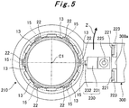
- a clamping device according to a third embodiment of the present invention is described with reference to Figs. 4 and 5 .
- a transport device configured to transport the securing member is further provided to the clamping device according to the second embodiment described above.
- instruments that are the same as those of the clamping device according to the second embodiment are given the same reference numerals, and are not described again.
- the clamping device further includes a transport device 200 configured to transport the securing member 10.
- the transport device 200 has a support table 210 configured to support the securing member 10 and a moving mechanism (moving means) 220 configured to move the support table 210 upward and downward.
- the support table 210 is provided with an opening portion 211 and a step portion 212 along the opening portion 211.
- the opening portion 211 of the support table 210 is formed to allow insertion of the mount table 110, the collet 120, the guide member 130, and the pressing-force applying instrument 20.
- the step portion 212 is formed to allow the lower end portion of the securing member 10 to be fitted thereinto.
- the securing member 10 can be supported at a predetermined position on an upper surface portion 210a of the support table 210.
- a phase adjustment mechanism (phase adjustment means) 230 configured to adjust the phase of the securing member 10 is provided to the support table 210 at a position adjacent to the step portion 212.
- the phase adjustment mechanism 230 includes a cylinder 231 and a piston rod 232 movable toward and away from the securing member 10.
- a tip end portion of the piston rod 232 is formed into a shape that can be fitted into a recessed portion 15 formed at an outer circumferential portion 12b of the securing member 10.
- the phase of the securing member 10 can be adjusted.
- the moving mechanism 220 is provided to a front surface portion 300a of a column 300 of a machine tool for machining the workpiece 101.
- the moving mechanism 220 has: rails 221 extending vertically; brackets 222 configured to secure lower end portions of the rails 221 to a base end portion of the support table 210; sliding portions 223, 223 which are provided to the front surface portion 300a of the column 300 and in which the respective rails 221 are slidable; and a cylinder 224.
- a piston rod 225 is provided to the cylinder 224 in such a manner as to be capable of advancing and retreating (moving upward and downward).
- a tip end portion 225a of the piston rod 225 is secured to the support table.
- the support table 210 moves upward and downward along with the advancing and retreating motion of the piston rod 225.
- the cylinder 224 is secured to the front surface portion 300a of the column 300 of the machine tool by means of a securing instrument (not shown).
- the workpiece 101 is placed on the reference surface 111 of the mount table 110, and the collet 120 is drawn downward.
- the workpiece 101 is placed on the reference surface 111 of the mount table 110 with centering of the workpiece 101 being completed.
- the column 300 is turned to locate the moving mechanism 220 at a position facing the workpiece 101. That is, the securing member 10 is located above the workpiece 101.
- the support table 210 is moved downward along the rails 221 by extending the piston rod 225.
- the mount table 110 is turned to couple the securing member 10 to the pressing-force applying instrument 20.
- the support table 210 is moved further downward.
- a tool is placed in an area surrounded by the inner circumferential surface 101a of the workpiece 101, and the inner circumferential surface 101a of the workpiece 101 is finished by grinding and the like.
- the tool is moved upward from the area surrounded by the inner circumferential surface 101a of the workpiece 101, so as to withdraw the tool to a position away from the upper area of the workpiece 101.
- the piston rod 225 of the moving mechanism 220 is retracted to move the support table 210 upward along the rails 221.
- the step portion 212 of the support table 210 is placed near the lower end portion of the securing member 10.
- the mount table 110 is turned as necessary.
- the piston rod 232 of the phase adjustment mechanism 230 is extended to insert the tip end portion of the piston rod 232 to the recessed portion 15 of the securing member 10.
- the mount table 110 is turned to release the coupling between the securing member 10 and the pressing-force applying instrument 20.
- the piston rod 225 of the moving mechanism 220 is retracted to move the support table 210 and the securing member 10 upward along the rails 221.
- the column 300 is turned as necessary.
- the securing member 10 is placed at a position away from the position above the workpiece 101.
- a clamping force for clamping the workpiece 101 to the mount table 110 can be improved, compared to the conventional clamping device configured to use claw portions to apply a pressing force toward the outer circumferential surface of a workpiece or the conventional clamping device configured to use fingers or arms to apply a pressing force toward the end surface of a workpiece. Moreover, safety improvement can be accomplished.
- the transport device 200 since the transport device 200 is included, the securing member 10 can be transported. Accordingly, the securing member 10 can be replaced easily, and the workpiece 101 can be withdrawn. Thus, further safety improvement can be accomplished.
- the transport device 200 is configured with the support table 210 and the moving mechanism 220, the device is simple as a whole. Thus, increase in facility costs can be suppressed.
- phase adjustment mechanism 230 By further including the phase adjustment mechanism 230, phase alignment between the securing member 10 and the pressing-force applying instrument 20 can be easily done. Thereby, the work can be performed with high efficiency.
- the present invention is applied to a clamping device configured to perform centering of the workpiece 101 by using the collet 120 in the above description, the present invention is also applicable to a clamping device configured to perform the workpiece centering by using the reference surface of the step portion provided to the mount table.
- the clamping device according to the present invention can improve a clamping force for clamping a workpiece, whose inner circumferential surface is to be machined, to a mount table, and can also improve safety; therefore, the clamping device is beneficial in the machine tool industry and the like.
Landscapes
- Engineering & Computer Science (AREA)
- Mechanical Engineering (AREA)
- Jigs For Machine Tools (AREA)
- Gear Processing (AREA)
- Automatic Assembly (AREA)
Claims (6)
- Dispositif de serrage comprenant une table de montage (30) ayant une partie formant ouverture (30a) prévue dans son centre, une partie de gradin (31) prévue au niveau d'un bord de la partie formant ouverture (30a) et ayant une surface de référence (32) sur laquelle une pièce à usiner (101) doit être placée, le dispositif de serrage étant configuré pour serrer la pièce à usiner (101) placée sur la surface de référence (32),
le dispositif de serrage comprenant en outre :
un organe de fixation (10) ayant :une partie formant plaque inférieure en forme de disque (11) dans laquelle une partie formant ouverture (11a) est formée et qui vient en contact de surface avec une surface d'extrémité de la pièce à usiner (101) placée sur la surface de référence (32) de la table de montage (30), la partie formant ouverture (11a) étant supérieure à un diamètre interne de la pièce à usiner (101) et inférieure à un diamètre externe de la pièce à usiner (101), etune partie cylindrique (12) qui a une forme cylindrique raccordée à une partie de bord de la partie de plaque inférieure (11),caractérisé en ce que la partie cylindrique comprend en outre :une pluralité de parties formant griffes (13) et une partie formant saillie (14), les parties formant griffes (13) étant prévues à intervalles prédéterminés dans une direction circonférentielle et faisant saillie vers un centre, la partie formant saillie (14) étant formée sur toute une circonférence d'une partie d'extrémité de base de la partie cylindrique (12) et faisant saillie vers le centre ; etun moyen d'application de force de pression (20) pour appliquer une force de pression sur l'organe de fixation (10) vers la surface d'extrémité de la pièce à usiner (101), le moyen d'application de force de pression (20) ayant une forme cylindrique entourant la table de montage (30) et comprenant une première partie formant saillie externe (21) faisant saillie radialement sur toute la circonférence d'une partie au-dessous d'une partie circonférentielle externe (20a) du moyen d'application de force de pression (20) et une pluralité de secondes parties formant saillies externes (22) qui sont formées dans des positions circonférentielles au-dessus de la partie circonférentielle externe (20a) du moyen d'application de force de pression (20) et faisant saillie radialement, la première partie formant saillie externe (21) et les secondes parties formant saillies externes (22) pouvant être couplées aux parties formant griffes (13) et à la partie formant saillie (14),le moyen d'application de force de pression (20) est fixé à la table de montage (30) afin d'être mobile vers le haut et vers le bas, etune première chambre hydraulique (41) et une seconde chambre hydraulique (42) pouvant fournir et décharger de l'huile hydraulique, sont formées par une partie formant saillie (23) prévue sur une partie circonférentielle interne du moyen d'application de force de pression (20) et par une partie formant rainure (34) qui est formée au niveau d'une partie circonférentielle externe de la table de montage (30) et dans laquelle la partie formant saillie (23) du moyen d'application de force de pression (20) est montée,le fait d'amener l'huile hydraulique à la première chambre hydraulique (41) amène le moyen d'application de force de pression (20) à solliciter la pièce à usiner (101) vers la surface de référence (32) de la table de montage (30) par le biais de l'organe de fixation (10) et à serrer la pièce à usiner (101), etle fait d'amener l'huile hydraulique à la seconde chambre hydraulique (42) amène le moyen d'application de force de pression (20) à relâcher la force de pression de la pièce à usiner (101) vers la surface de référence (32) de la table de montage (30) par le biais de l'organe de fixation (10) et à desserrer la pièce à usiner (101). - Dispositif de serrage comprenant une table de montage (110) ayant une partie d'ouverture (110a) prévue dans son centre et ayant une surface de référence (111) sur laquelle la pièce à usiner (101) doit être placée ;
un organe de guidage (130) étant placé radialement à l'extérieur de la table de montage (110) et ayant une partie formant inclinaison (131) augmentant du point de vue du diamètre vers le haut et étant formée au niveau de la partie circonférentielle interne de l'organe de guidage (130) dans une position à proximité d'une partie d'extrémité supérieure (130a) ; et
une pince de serrage (120) étant placée entre la table de montage (110) et l'organe de guidage (130) et ayant une partie progressivement rétrécie (121) formée au niveau de sa partie circonférentielle externe dans une position à proximité d'une partie d'extrémité supérieure (120a),
le dispositif de serrage comprenant :un organe de fixation (10) ayant :une partie formant plaque inférieure en forme de disque (11) dans laquelle une partie formant ouverture (11a) est formée et qui vient en contact de surface avec une surface d'extrémité de la pièce à usiner (101) placée sur la surface de référence (111) de la table de montage (110), la partie formant ouverture (11a) étant supérieure à un diamètre interne de la pièce à usiner (101) et inférieure à un diamètre externe de la pièce à usiner (101), etune partie cylindrique (12) qui a une forme cylindrique raccordée à une partie de bord de la partie formant plaque inférieure (11) et qui comprend une pluralité de parties formant griffes (13) et une partie formant saillie (14), les parties formant griffes (13) étant prévues à intervalles prédéterminés dans une direction circonférentielle et faisant saillie vers un centre, la partie formant saillie (14) étant formée sur toute une circonférence d'une partie d'extrémité de base de la partie cylindrique (12) et faisant saillie vers le centre ; etle moyen d'application de force de pression (20) pour appliquer une force de pression sur l'organe de fixation (10) vers la surface d'extrémité de la pièce à usiner (101), le moyen d'application de force de pression (20) ayant une force cylindrique entourant l'organe de guidage (130) et comprenant une première partie formant saillie externe (21) faisant saillie radialement sur toute la circonférence d'une partie au-dessous d'une partie circonférentielle externe (20a) du moyen d'application de force de pression (20) et une pluralité de secondes parties formant saillies externes (22) étant formées dans des positions circonférentielles au-dessus de la partie circonférentielle externe (20a) du moyen d'application de force de pression (20) et faisant saillie radialement, la première partie formant saillie externe (21) et les secondes parties formant saillies externes (22) pouvant être couplées aux parties formant griffes (13) et à la partie formant saillie (14),le moyen d'application de force de pression (20) est prévu sur l'organe de guidage (130) afin d'être mobile vers le haut et vers le bas,une première chambre hydraulique (41) et une seconde chambre hydraulique (42) pouvant fournir et décharger l'huile hydraulique sont formées par une partie formant saillie (23) prévue sur une partie circonférentielle interne du moyen d'application de force de pression (20) et par une partie formant rainure (34) qui est formée au niveau d'une partie circonférentielle externe de l'organe de guidage (130) et dans laquelle la partie formant saillie (23) du moyen d'application de force de pression (20) est montée,le fait d'amener l'huile hydraulique à la première chambre hydraulique (41) amène le moyen d'application de force de pression (20) à solliciter la pièce à usiner (101) vers la surface de référence (111) de la table de montage (110) par le biais de l'organe de fixation (10) et à serrer la pièce à usiner (101), etle fait d'amener l'huile hydraulique à la seconde chambre hydraulique (42) amène le moyen d'application de force de pression (20) à relâcher la force de pression de la pièce à usiner (101) vers la surface de référence (111) de la table de montage (110) par le biais de l'organe de fixation (10) et à desserrer la pièce à usiner (101). - Dispositif de serrage selon la revendication 1 ou 2, caractérisé en ce que l'organe de fixation (10) et le moyen d'application de force de pression (20) sont couplés entre eux par un mécanisme à baïonnette.
- Dispositif de serrage selon la revendication 3, le dispositif de serrage étant caractérisé en ce qu'il comprend en outre un moyen de transport pour transporter l'organe de fixation.
- Dispositif de serrage selon la revendication 4, caractérisé en ce que :
le moyen de transport (200) comprend une table de support (210) configurée pour supporter l'organe de fixation (10), et un moyen de déplacement (220) pour déplacer la table de support (210) vers le haut et vers le bas. - Dispositif de serrage selon la revendication 5, caractérisé en ce que :le dispositif de serrage comprend en outre un moyen d'ajustement de phase (230) pour ajuster une phase de l'organe de fixation (10), etle moyen d'ajustement de phase (230) comprend une tige de piston (232) prévue sur la table de support (210), pouvant se déplacer vers et à distance de l'organe de fixation (10) et pouvant être montée dans une partie évidée (15) formée au niveau d'une surface circonférentielle (12b) de l'organe de fixation (10).
Applications Claiming Priority (2)
| Application Number | Priority Date | Filing Date | Title |
|---|---|---|---|
| JP2010236422A JP5615129B2 (ja) | 2010-10-21 | 2010-10-21 | クランプ装置 |
| PCT/JP2011/071082 WO2012053300A1 (fr) | 2010-10-21 | 2011-09-15 | Dispositif de bridage |
Publications (3)
| Publication Number | Publication Date |
|---|---|
| EP2631028A1 EP2631028A1 (fr) | 2013-08-28 |
| EP2631028A4 EP2631028A4 (fr) | 2017-10-18 |
| EP2631028B1 true EP2631028B1 (fr) | 2020-05-27 |
Family
ID=45975022
Family Applications (1)
| Application Number | Title | Priority Date | Filing Date |
|---|---|---|---|
| EP11834142.9A Active EP2631028B1 (fr) | 2010-10-21 | 2011-09-15 | Dispositif de bridage |
Country Status (7)
| Country | Link |
|---|---|
| US (1) | US9421654B2 (fr) |
| EP (1) | EP2631028B1 (fr) |
| JP (1) | JP5615129B2 (fr) |
| CN (1) | CN103153515B (fr) |
| BR (1) | BR112013007609A2 (fr) |
| TW (1) | TWI483806B (fr) |
| WO (1) | WO2012053300A1 (fr) |
Families Citing this family (18)
| Publication number | Priority date | Publication date | Assignee | Title |
|---|---|---|---|---|
| JP2015020237A (ja) * | 2013-07-18 | 2015-02-02 | 株式会社ディスコ | 切削装置 |
| JP6108999B2 (ja) * | 2013-07-18 | 2017-04-05 | 株式会社ディスコ | 切削装置 |
| CN203702759U (zh) * | 2014-01-20 | 2014-07-09 | 思博特有限公司 | 一种轻便的旋转自锁式快拆锁扣装置 |
| JP5863929B1 (ja) * | 2014-10-29 | 2016-02-17 | マキノジェイ株式会社 | 加工装置 |
| CN105345549A (zh) * | 2015-12-04 | 2016-02-24 | 泸州远程工程机械有限公司 | 一种三面限位的平板夹具 |
| CN109562498B (zh) * | 2016-07-12 | 2021-06-08 | 住友电气工业株式会社 | 机加工夹具及机加工方法 |
| CN108655513B (zh) * | 2018-08-06 | 2020-03-10 | 佛山市瑞信和机械设备有限公司 | 一种高效齿轮加工机床用齿轮夹具 |
| CN109848487B (zh) * | 2019-03-06 | 2020-09-15 | 湖南金程齿轮传动机械有限公司 | 一种螺旋伞齿轮磨齿夹具 |
| CN110666577B (zh) * | 2019-09-26 | 2021-07-20 | 西安北方光电科技防务有限公司 | 一种用于高精度弱刚性整体部件重量调校的加工方法 |
| CN111515473A (zh) * | 2020-04-28 | 2020-08-11 | 秦川机床工具集团股份公司 | 一种用于转向器摇臂轴扇形齿轮磨削加工的夹具以及装夹方法 |
| CN111558841B (zh) * | 2020-05-13 | 2021-11-02 | 宁波正元铜合金有限公司 | 一种液压增材制造加工装置 |
| CN111633284A (zh) * | 2020-06-15 | 2020-09-08 | 香河华美齿轮有限公司 | 用于固定齿圈的夹具 |
| CN112207326B (zh) * | 2020-09-30 | 2022-10-04 | 上汽通用五菱汽车股份有限公司 | 加工刀具调整装置 |
| CN113111466B (zh) * | 2021-04-29 | 2023-03-14 | 南昌航空大学 | 基于topsis和mga的夹具装夹布局方法 |
| CN114434171B (zh) * | 2022-03-22 | 2024-02-06 | 福建省龙治智能设备有限公司 | 一种高精度稳定型镗铣加工中心 |
| CN114714446B (zh) * | 2022-04-25 | 2022-11-04 | 浙江金立方门业有限公司 | 一种多轴角度限位的门业产品加工用定位夹持装置 |
| CN117817055A (zh) * | 2024-02-23 | 2024-04-05 | 重庆大合汽车配件有限公司 | 一种桥锥齿轮铣削加工专用夹具 |
| CN117983902B (zh) * | 2024-04-07 | 2024-06-04 | 常州江泉传动科技有限公司 | 一种齿轮减速机生产用行星齿轮加工装置 |
Family Cites Families (57)
| Publication number | Priority date | Publication date | Assignee | Title |
|---|---|---|---|---|
| US1021011A (en) * | 1908-03-02 | 1912-03-26 | Brown Life Gear Company | Chuck for holding and centering gears. |
| US1110396A (en) * | 1913-11-26 | 1914-09-15 | Charles J Marks | Gear-truing chuck. |
| US1401192A (en) * | 1919-04-25 | 1921-12-27 | Hessbright Mfg Company | Chuck |
| DE397804C (de) * | 1919-11-15 | 1924-06-28 | Nordiska Kullager Ab | Einspannvorrichtung |
| US1443651A (en) * | 1921-07-22 | 1923-01-30 | Hessbright Mfg Company | Chuck |
| US1685235A (en) * | 1924-07-02 | 1928-09-25 | Heald Machine Co | Chuck |
| US1783596A (en) * | 1925-01-16 | 1930-12-02 | Heald Machine Co | Work holder |
| US2018088A (en) * | 1932-05-16 | 1935-10-22 | Cimatool Company | Machine tool |
| US2443895A (en) * | 1943-12-20 | 1948-06-22 | Bryant Grinder Corp | Bevel gear holding fixture |
| US2635395A (en) * | 1951-05-19 | 1953-04-21 | Bryant Grinder Corp | Machine for grinding internal surfaces concentric with external surfaces |
| DE867038C (de) * | 1951-07-07 | 1953-02-16 | Henschel & Sohn G M B H | Spannfutter fuer Kegelraeder |
| US2696986A (en) * | 1952-07-29 | 1954-12-14 | Bryant Grinder Corp | Work-holding mechanism |
| US2706369A (en) * | 1953-05-07 | 1955-04-19 | Bryant Grinder Corp | Centerless grinding machine with loading and unloading mechanism |
| US2754641A (en) * | 1954-02-01 | 1956-07-17 | Bryant Grinder Corp | Work holding and clamping mechanism for centerless grinding machines |
| US2861402A (en) * | 1955-03-10 | 1958-11-25 | Wagner Electric Corp | Work holder |
| US2889668A (en) * | 1955-04-07 | 1959-06-09 | Ulvsunda Verkst Er Aktiebolag | Work holders of the centerless type for grinding machines |
| US2852263A (en) * | 1956-05-14 | 1958-09-16 | Woodworth Co N A | Arbor twist chuck |
| US2951320A (en) * | 1957-08-14 | 1960-09-06 | Heald Machine Co | Clamp for internal grinding machine |
| US2981037A (en) * | 1958-04-17 | 1961-04-25 | Bryant Grinder Corp | Workholder and method for internal grinding |
| US3056238A (en) * | 1960-06-24 | 1962-10-02 | Heald Machine Co | Grinding machine |
| US3079736A (en) * | 1960-08-22 | 1963-03-05 | Plastic Contact Lens Company | Toric lens tool |
| US3273292A (en) * | 1963-10-16 | 1966-09-20 | Cincinnati Milling Machine Co | Machine tool headstock |
| US3554081A (en) * | 1969-04-17 | 1971-01-12 | Chicago Rawhide Mfg Co | Seal unit and method of manufacturing |
| FR2105381A5 (fr) * | 1970-09-03 | 1972-04-28 | Guillemin Sergeot Pegord | |
| JPS5135592Y2 (fr) * | 1971-12-10 | 1976-09-01 | ||
| US3813820A (en) * | 1973-03-29 | 1974-06-04 | Engelhard Min & Chem | Sheet glass core drilling machine |
| CH586590A5 (en) * | 1974-01-14 | 1977-04-15 | Glocker Paul Leo | Mandrel for accurate centring of machined part bore - has compressed air cushion supplied through passages in spigot and body |
| US3973764A (en) * | 1975-08-08 | 1976-08-10 | Corning Glass Works | Clamping apparatus |
| US4312513A (en) * | 1979-08-10 | 1982-01-26 | J & S Tool Company | Gear holding hydraulically actuated chuck |
| US4307954A (en) * | 1980-08-18 | 1981-12-29 | Ludwig Robert B | Bayonet mount |
| JPH0623821B2 (ja) * | 1983-09-02 | 1994-03-30 | ミノルタカメラ株式会社 | バヨネットマウント装置とこの装置を用いる光学機器 |
| DE8503153U1 (de) * | 1985-02-06 | 1985-05-09 | Benteler-Werke Ag Werk Neuhaus, 4790 Paderborn | Bohrvorrichtung zum bohren von bruchempfindlichen platten |
| DE3605615A1 (de) * | 1986-02-21 | 1987-08-27 | Schloemann Siemag Ag | Wellenzapfen mit bajonettverschluss, insbesondere zum festlegen des innenzylinders einer hydraulischen abziehvorrichtung fuer walzenlager auf dem walzenzapfen |
| GB8700906D0 (en) * | 1987-01-16 | 1987-02-18 | Tbs Eng Cheltenham | Handling apparatus |
| JPH0727056Y2 (ja) | 1988-12-08 | 1995-06-21 | いすゞ自動車株式会社 | 内歯車研削用治具 |
| IT1234229B (it) * | 1988-12-16 | 1992-05-06 | Axis Spa | Metodi ed apparecchiature per realizzare parti di motori elettrici impieganti pallets con supporto amovibile del pezzo in lavorazione |
| US4955763A (en) * | 1989-02-10 | 1990-09-11 | Toledo Automated Concepts, Inc. | Glass drilling machine |
| US5188278A (en) * | 1990-11-22 | 1993-02-23 | A & S Corporation | Friction welding method for joining a rim and a disc of a disc wheel and the apparatus therefor |
| US5251510A (en) * | 1991-09-17 | 1993-10-12 | Dana Corporation | Ring gear fixture and machining process therefor |
| JP2803449B2 (ja) * | 1992-04-02 | 1998-09-24 | 株式会社デンソー | 物体の保持装置 |
| JPH0727056A (ja) | 1993-07-06 | 1995-01-27 | Hitachi Ltd | ポンプ |
| US5429376A (en) * | 1994-03-01 | 1995-07-04 | General Manufacturing Systems, Inc. | Fluid-operated collet chuck with centering fingers |
| US5782151A (en) * | 1995-08-07 | 1998-07-21 | Kitagawa Iron Works Co., Ltd. | Workpiece transfer apparatus |
| US6173971B1 (en) * | 1999-05-14 | 2001-01-16 | Tsung-Lin Shen | Plunger type rotary chuck assemblies |
| JP2001047337A (ja) * | 1999-08-05 | 2001-02-20 | Honda Motor Co Ltd | 内面加工治具 |
| JP4288124B2 (ja) | 2003-09-04 | 2009-07-01 | 株式会社北川鉄工所 | フィンガチャック |
| CN2717599Y (zh) * | 2004-08-05 | 2005-08-17 | 天津第一机床总厂 | 弧齿锥齿轮加工机床工件主轴夹紧装置 |
| JP4683613B2 (ja) * | 2004-11-30 | 2011-05-18 | 武蔵精密工業株式会社 | 傘歯車用チャック |
| US8087675B2 (en) * | 2006-08-24 | 2012-01-03 | Korson Daniel G | Chuck holder incorporating independent arrayed wedge clamps for clamping such as irregularly shaped and thin wall parts with a minimum of deformation |
| CN201091925Y (zh) * | 2007-06-18 | 2008-07-30 | 西安飞机工业(集团)有限责任公司 | 刀具快卸夹头 |
| US7559359B2 (en) * | 2007-08-27 | 2009-07-14 | Williams John R | Spring preloaded bearing assembly and well drilling equipment comprising same |
| CN201073739Y (zh) * | 2007-09-28 | 2008-06-18 | 济南一机床集团有限公司 | 一种数控立式车床夹具 |
| JP2010194635A (ja) | 2009-02-24 | 2010-09-09 | Mitsubishi Heavy Ind Ltd | クランプ装置 |
| JP2010194636A (ja) * | 2009-02-24 | 2010-09-09 | Mitsubishi Heavy Ind Ltd | 内歯車ワーク位置決め用治具 |
| CN101954516A (zh) * | 2009-07-13 | 2011-01-26 | 铜陵皖江集团新高机电有限公司 | 齿轮铣床胎夹具 |
| CN201446409U (zh) * | 2009-07-27 | 2010-05-05 | 山东联诚集团有限公司 | 一种具有轴承孔工件的加工夹具 |
| CN201824029U (zh) * | 2010-07-29 | 2011-05-11 | 四川省内江庆隆机床有限公司 | 一种插内齿工装 |
-
2010
- 2010-10-21 JP JP2010236422A patent/JP5615129B2/ja active Active
-
2011
- 2011-09-15 CN CN201180046283.8A patent/CN103153515B/zh active Active
- 2011-09-15 WO PCT/JP2011/071082 patent/WO2012053300A1/fr not_active Ceased
- 2011-09-15 BR BR112013007609A patent/BR112013007609A2/pt not_active IP Right Cessation
- 2011-09-15 US US13/824,824 patent/US9421654B2/en active Active
- 2011-09-15 EP EP11834142.9A patent/EP2631028B1/fr active Active
- 2011-09-22 TW TW100134187A patent/TWI483806B/zh active
Non-Patent Citations (1)
| Title |
|---|
| None * |
Also Published As
| Publication number | Publication date |
|---|---|
| BR112013007609A2 (pt) | 2016-08-09 |
| EP2631028A1 (fr) | 2013-08-28 |
| TWI483806B (zh) | 2015-05-11 |
| JP2012086324A (ja) | 2012-05-10 |
| TW201233490A (en) | 2012-08-16 |
| CN103153515A (zh) | 2013-06-12 |
| WO2012053300A1 (fr) | 2012-04-26 |
| EP2631028A4 (fr) | 2017-10-18 |
| US20130228960A1 (en) | 2013-09-05 |
| CN103153515B (zh) | 2015-05-27 |
| US9421654B2 (en) | 2016-08-23 |
| JP5615129B2 (ja) | 2014-10-29 |
Similar Documents
| Publication | Publication Date | Title |
|---|---|---|
| EP2631028B1 (fr) | Dispositif de bridage | |
| CN205324774U (zh) | 一种薄壁零件内涨式夹具 | |
| JP2011230280A (ja) | 電動チャック | |
| US10799957B2 (en) | Chuck device | |
| JP5538012B2 (ja) | 工作機械 | |
| CN105492158A (zh) | 刀夹 | |
| CN209681722U (zh) | 一种薄壁套筒内孔车削用夹具 | |
| CN201483261U (zh) | 自动调心组合夹具 | |
| JPWO2004108336A1 (ja) | 放電加工機及びその加工方法 | |
| US20040165962A1 (en) | Internal broaching machine and internal broach | |
| US20200269368A1 (en) | Tool carrier and tool holder | |
| CN102837205B (zh) | 液压自定心内腔涨紧机构 | |
| CN102101195B (zh) | 多工位精密加工方形壳体的液压铣夹具 | |
| JP6327663B2 (ja) | ホルダ体およびワーククランプ装置 | |
| CN215469711U (zh) | 一种箱体同心定位夹具 | |
| CN201529913U (zh) | 无卡盘车削薄壁套夹具 | |
| JP2017213635A (ja) | チャック装置及びワークチャック方法 | |
| CN101623830B (zh) | 自动调心组合夹具 | |
| KR200462344Y1 (ko) | 유압 척 커버 | |
| CN221388968U (zh) | 一种车床夹头 | |
| JP3233226U (ja) | アダプタとワークとの芯合わせ装置 | |
| JP4907021B2 (ja) | 工作物を加工する方法とそれを実行する中心ピンを備えるチャック | |
| CN219025972U (zh) | 一种内涨夹具 | |
| JP6382682B2 (ja) | 工具ホルダ | |
| JP2001087904A (ja) | 割込み式テールストック装置及びこれを備えた2主軸対向旋盤 |
Legal Events
| Date | Code | Title | Description |
|---|---|---|---|
| PUAI | Public reference made under article 153(3) epc to a published international application that has entered the european phase |
Free format text: ORIGINAL CODE: 0009012 |
|
| 17P | Request for examination filed |
Effective date: 20130328 |
|
| AK | Designated contracting states |
Kind code of ref document: A1 Designated state(s): AL AT BE BG CH CY CZ DE DK EE ES FI FR GB GR HR HU IE IS IT LI LT LU LV MC MK MT NL NO PL PT RO RS SE SI SK SM TR |
|
| DAX | Request for extension of the european patent (deleted) | ||
| RAP1 | Party data changed (applicant data changed or rights of an application transferred) |
Owner name: MITSUBISHI HEAVY INDUSTRIES MACHINE TOOL CO., LTD. |
|
| RA4 | Supplementary search report drawn up and despatched (corrected) |
Effective date: 20170914 |
|
| RIC1 | Information provided on ipc code assigned before grant |
Ipc: B23F 23/06 20060101AFI20170908BHEP Ipc: B23F 23/08 20060101ALI20170908BHEP Ipc: B23B 31/02 20060101ALI20170908BHEP Ipc: B23Q 3/06 20060101ALI20170908BHEP |
|
| STAA | Information on the status of an ep patent application or granted ep patent |
Free format text: STATUS: EXAMINATION IS IN PROGRESS |
|
| 17Q | First examination report despatched |
Effective date: 20181211 |
|
| GRAP | Despatch of communication of intention to grant a patent |
Free format text: ORIGINAL CODE: EPIDOSNIGR1 |
|
| STAA | Information on the status of an ep patent application or granted ep patent |
Free format text: STATUS: GRANT OF PATENT IS INTENDED |
|
| INTG | Intention to grant announced |
Effective date: 20191217 |
|
| GRAS | Grant fee paid |
Free format text: ORIGINAL CODE: EPIDOSNIGR3 |
|
| GRAA | (expected) grant |
Free format text: ORIGINAL CODE: 0009210 |
|
| STAA | Information on the status of an ep patent application or granted ep patent |
Free format text: STATUS: THE PATENT HAS BEEN GRANTED |
|
| AK | Designated contracting states |
Kind code of ref document: B1 Designated state(s): AL AT BE BG CH CY CZ DE DK EE ES FI FR GB GR HR HU IE IS IT LI LT LU LV MC MK MT NL NO PL PT RO RS SE SI SK SM TR |
|
| REG | Reference to a national code |
Ref country code: GB Ref legal event code: FG4D |
|
| REG | Reference to a national code |
Ref country code: CH Ref legal event code: EP |
|
| REG | Reference to a national code |
Ref country code: DE Ref legal event code: R096 Ref document number: 602011067069 Country of ref document: DE |
|
| REG | Reference to a national code |
Ref country code: AT Ref legal event code: REF Ref document number: 1274056 Country of ref document: AT Kind code of ref document: T Effective date: 20200615 |
|
| REG | Reference to a national code |
Ref country code: CH Ref legal event code: NV Representative=s name: HEPP WENGER RYFFEL AG, CH |
|
| REG | Reference to a national code |
Ref country code: LT Ref legal event code: MG4D |
|
| PG25 | Lapsed in a contracting state [announced via postgrant information from national office to epo] |
Ref country code: SE Free format text: LAPSE BECAUSE OF FAILURE TO SUBMIT A TRANSLATION OF THE DESCRIPTION OR TO PAY THE FEE WITHIN THE PRESCRIBED TIME-LIMIT Effective date: 20200527 Ref country code: LT Free format text: LAPSE BECAUSE OF FAILURE TO SUBMIT A TRANSLATION OF THE DESCRIPTION OR TO PAY THE FEE WITHIN THE PRESCRIBED TIME-LIMIT Effective date: 20200527 Ref country code: PT Free format text: LAPSE BECAUSE OF FAILURE TO SUBMIT A TRANSLATION OF THE DESCRIPTION OR TO PAY THE FEE WITHIN THE PRESCRIBED TIME-LIMIT Effective date: 20200928 Ref country code: IS Free format text: LAPSE BECAUSE OF FAILURE TO SUBMIT A TRANSLATION OF THE DESCRIPTION OR TO PAY THE FEE WITHIN THE PRESCRIBED TIME-LIMIT Effective date: 20200927 Ref country code: GR Free format text: LAPSE BECAUSE OF FAILURE TO SUBMIT A TRANSLATION OF THE DESCRIPTION OR TO PAY THE FEE WITHIN THE PRESCRIBED TIME-LIMIT Effective date: 20200828 Ref country code: FI Free format text: LAPSE BECAUSE OF FAILURE TO SUBMIT A TRANSLATION OF THE DESCRIPTION OR TO PAY THE FEE WITHIN THE PRESCRIBED TIME-LIMIT Effective date: 20200527 Ref country code: NO Free format text: LAPSE BECAUSE OF FAILURE TO SUBMIT A TRANSLATION OF THE DESCRIPTION OR TO PAY THE FEE WITHIN THE PRESCRIBED TIME-LIMIT Effective date: 20200827 |
|
| REG | Reference to a national code |
Ref country code: NL Ref legal event code: MP Effective date: 20200527 |
|
| PG25 | Lapsed in a contracting state [announced via postgrant information from national office to epo] |
Ref country code: LV Free format text: LAPSE BECAUSE OF FAILURE TO SUBMIT A TRANSLATION OF THE DESCRIPTION OR TO PAY THE FEE WITHIN THE PRESCRIBED TIME-LIMIT Effective date: 20200527 Ref country code: RS Free format text: LAPSE BECAUSE OF FAILURE TO SUBMIT A TRANSLATION OF THE DESCRIPTION OR TO PAY THE FEE WITHIN THE PRESCRIBED TIME-LIMIT Effective date: 20200527 Ref country code: BG Free format text: LAPSE BECAUSE OF FAILURE TO SUBMIT A TRANSLATION OF THE DESCRIPTION OR TO PAY THE FEE WITHIN THE PRESCRIBED TIME-LIMIT Effective date: 20200827 Ref country code: HR Free format text: LAPSE BECAUSE OF FAILURE TO SUBMIT A TRANSLATION OF THE DESCRIPTION OR TO PAY THE FEE WITHIN THE PRESCRIBED TIME-LIMIT Effective date: 20200527 |
|
| REG | Reference to a national code |
Ref country code: AT Ref legal event code: MK05 Ref document number: 1274056 Country of ref document: AT Kind code of ref document: T Effective date: 20200527 |
|
| PG25 | Lapsed in a contracting state [announced via postgrant information from national office to epo] |
Ref country code: AL Free format text: LAPSE BECAUSE OF FAILURE TO SUBMIT A TRANSLATION OF THE DESCRIPTION OR TO PAY THE FEE WITHIN THE PRESCRIBED TIME-LIMIT Effective date: 20200527 Ref country code: NL Free format text: LAPSE BECAUSE OF FAILURE TO SUBMIT A TRANSLATION OF THE DESCRIPTION OR TO PAY THE FEE WITHIN THE PRESCRIBED TIME-LIMIT Effective date: 20200527 |
|
| PG25 | Lapsed in a contracting state [announced via postgrant information from national office to epo] |
Ref country code: CZ Free format text: LAPSE BECAUSE OF FAILURE TO SUBMIT A TRANSLATION OF THE DESCRIPTION OR TO PAY THE FEE WITHIN THE PRESCRIBED TIME-LIMIT Effective date: 20200527 Ref country code: IT Free format text: LAPSE BECAUSE OF FAILURE TO SUBMIT A TRANSLATION OF THE DESCRIPTION OR TO PAY THE FEE WITHIN THE PRESCRIBED TIME-LIMIT Effective date: 20200527 Ref country code: ES Free format text: LAPSE BECAUSE OF FAILURE TO SUBMIT A TRANSLATION OF THE DESCRIPTION OR TO PAY THE FEE WITHIN THE PRESCRIBED TIME-LIMIT Effective date: 20200527 Ref country code: RO Free format text: LAPSE BECAUSE OF FAILURE TO SUBMIT A TRANSLATION OF THE DESCRIPTION OR TO PAY THE FEE WITHIN THE PRESCRIBED TIME-LIMIT Effective date: 20200527 Ref country code: DK Free format text: LAPSE BECAUSE OF FAILURE TO SUBMIT A TRANSLATION OF THE DESCRIPTION OR TO PAY THE FEE WITHIN THE PRESCRIBED TIME-LIMIT Effective date: 20200527 Ref country code: AT Free format text: LAPSE BECAUSE OF FAILURE TO SUBMIT A TRANSLATION OF THE DESCRIPTION OR TO PAY THE FEE WITHIN THE PRESCRIBED TIME-LIMIT Effective date: 20200527 Ref country code: EE Free format text: LAPSE BECAUSE OF FAILURE TO SUBMIT A TRANSLATION OF THE DESCRIPTION OR TO PAY THE FEE WITHIN THE PRESCRIBED TIME-LIMIT Effective date: 20200527 Ref country code: SM Free format text: LAPSE BECAUSE OF FAILURE TO SUBMIT A TRANSLATION OF THE DESCRIPTION OR TO PAY THE FEE WITHIN THE PRESCRIBED TIME-LIMIT Effective date: 20200527 |
|
| PG25 | Lapsed in a contracting state [announced via postgrant information from national office to epo] |
Ref country code: SK Free format text: LAPSE BECAUSE OF FAILURE TO SUBMIT A TRANSLATION OF THE DESCRIPTION OR TO PAY THE FEE WITHIN THE PRESCRIBED TIME-LIMIT Effective date: 20200527 Ref country code: PL Free format text: LAPSE BECAUSE OF FAILURE TO SUBMIT A TRANSLATION OF THE DESCRIPTION OR TO PAY THE FEE WITHIN THE PRESCRIBED TIME-LIMIT Effective date: 20200527 |
|
| REG | Reference to a national code |
Ref country code: DE Ref legal event code: R097 Ref document number: 602011067069 Country of ref document: DE |
|
| PLBE | No opposition filed within time limit |
Free format text: ORIGINAL CODE: 0009261 |
|
| STAA | Information on the status of an ep patent application or granted ep patent |
Free format text: STATUS: NO OPPOSITION FILED WITHIN TIME LIMIT |
|
| PG25 | Lapsed in a contracting state [announced via postgrant information from national office to epo] |
Ref country code: MC Free format text: LAPSE BECAUSE OF FAILURE TO SUBMIT A TRANSLATION OF THE DESCRIPTION OR TO PAY THE FEE WITHIN THE PRESCRIBED TIME-LIMIT Effective date: 20200527 |
|
| 26N | No opposition filed |
Effective date: 20210302 |
|
| GBPC | Gb: european patent ceased through non-payment of renewal fee |
Effective date: 20200915 |
|
| PG25 | Lapsed in a contracting state [announced via postgrant information from national office to epo] |
Ref country code: SI Free format text: LAPSE BECAUSE OF FAILURE TO SUBMIT A TRANSLATION OF THE DESCRIPTION OR TO PAY THE FEE WITHIN THE PRESCRIBED TIME-LIMIT Effective date: 20200527 |
|
| REG | Reference to a national code |
Ref country code: BE Ref legal event code: MM Effective date: 20200930 |
|
| PG25 | Lapsed in a contracting state [announced via postgrant information from national office to epo] |
Ref country code: LU Free format text: LAPSE BECAUSE OF NON-PAYMENT OF DUE FEES Effective date: 20200915 |
|
| PG25 | Lapsed in a contracting state [announced via postgrant information from national office to epo] |
Ref country code: FR Free format text: LAPSE BECAUSE OF NON-PAYMENT OF DUE FEES Effective date: 20200930 |
|
| PG25 | Lapsed in a contracting state [announced via postgrant information from national office to epo] |
Ref country code: BE Free format text: LAPSE BECAUSE OF NON-PAYMENT OF DUE FEES Effective date: 20200930 Ref country code: IE Free format text: LAPSE BECAUSE OF NON-PAYMENT OF DUE FEES Effective date: 20200915 Ref country code: GB Free format text: LAPSE BECAUSE OF NON-PAYMENT OF DUE FEES Effective date: 20200915 |
|
| PG25 | Lapsed in a contracting state [announced via postgrant information from national office to epo] |
Ref country code: TR Free format text: LAPSE BECAUSE OF FAILURE TO SUBMIT A TRANSLATION OF THE DESCRIPTION OR TO PAY THE FEE WITHIN THE PRESCRIBED TIME-LIMIT Effective date: 20200527 Ref country code: MT Free format text: LAPSE BECAUSE OF FAILURE TO SUBMIT A TRANSLATION OF THE DESCRIPTION OR TO PAY THE FEE WITHIN THE PRESCRIBED TIME-LIMIT Effective date: 20200527 Ref country code: CY Free format text: LAPSE BECAUSE OF FAILURE TO SUBMIT A TRANSLATION OF THE DESCRIPTION OR TO PAY THE FEE WITHIN THE PRESCRIBED TIME-LIMIT Effective date: 20200527 |
|
| PG25 | Lapsed in a contracting state [announced via postgrant information from national office to epo] |
Ref country code: MK Free format text: LAPSE BECAUSE OF FAILURE TO SUBMIT A TRANSLATION OF THE DESCRIPTION OR TO PAY THE FEE WITHIN THE PRESCRIBED TIME-LIMIT Effective date: 20200527 |
|
| P01 | Opt-out of the competence of the unified patent court (upc) registered |
Effective date: 20230520 |
|
| REG | Reference to a national code |
Ref country code: CH Ref legal event code: U11 Free format text: ST27 STATUS EVENT CODE: U-0-0-U10-U11 (AS PROVIDED BY THE NATIONAL OFFICE) Effective date: 20251001 |
|
| PGFP | Annual fee paid to national office [announced via postgrant information from national office to epo] |
Ref country code: DE Payment date: 20250919 Year of fee payment: 15 |
|
| PGFP | Annual fee paid to national office [announced via postgrant information from national office to epo] |
Ref country code: CH Payment date: 20251001 Year of fee payment: 15 |