EP2631031A2 - Dispositif de transfert pour le transfert en propulsion d'éléments de compression sur un outil de traitement de tôle et outil de traitement de tôle doté d'un tel dispositif de transfert - Google Patents
Dispositif de transfert pour le transfert en propulsion d'éléments de compression sur un outil de traitement de tôle et outil de traitement de tôle doté d'un tel dispositif de transfert Download PDFInfo
- Publication number
- EP2631031A2 EP2631031A2 EP13151132.1A EP13151132A EP2631031A2 EP 2631031 A2 EP2631031 A2 EP 2631031A2 EP 13151132 A EP13151132 A EP 13151132A EP 2631031 A2 EP2631031 A2 EP 2631031A2
- Authority
- EP
- European Patent Office
- Prior art keywords
- transfer
- press
- tool
- coupling device
- transfer device
- Prior art date
- Legal status (The legal status is an assumption and is not a legal conclusion. Google has not performed a legal analysis and makes no representation as to the accuracy of the status listed.)
- Granted
Links
Images



Classifications
-
- B—PERFORMING OPERATIONS; TRANSPORTING
- B23—MACHINE TOOLS; METAL-WORKING NOT OTHERWISE PROVIDED FOR
- B23P—METAL-WORKING NOT OTHERWISE PROVIDED FOR; COMBINED OPERATIONS; UNIVERSAL MACHINE TOOLS
- B23P19/00—Machines for simply fitting together or separating metal parts or objects, or metal and non-metal parts, whether or not involving some deformation; Tools or devices therefor so far as not provided for in other classes
- B23P19/04—Machines for simply fitting together or separating metal parts or objects, or metal and non-metal parts, whether or not involving some deformation; Tools or devices therefor so far as not provided for in other classes for assembling or disassembling parts
- B23P19/06—Screw or nut setting or loosening machines
- B23P19/062—Pierce nut setting machines
-
- B—PERFORMING OPERATIONS; TRANSPORTING
- B21—MECHANICAL METAL-WORKING WITHOUT ESSENTIALLY REMOVING MATERIAL; PUNCHING METAL
- B21J—FORGING; HAMMERING; PRESSING METAL; RIVETING; FORGE FURNACES
- B21J15/00—Riveting
- B21J15/10—Riveting machines
- B21J15/30—Particular elements, e.g. supports; Suspension equipment specially adapted for portable riveters
- B21J15/32—Devices for inserting or holding rivets in position with or without feeding arrangements
-
- B—PERFORMING OPERATIONS; TRANSPORTING
- B23—MACHINE TOOLS; METAL-WORKING NOT OTHERWISE PROVIDED FOR
- B23P—METAL-WORKING NOT OTHERWISE PROVIDED FOR; COMBINED OPERATIONS; UNIVERSAL MACHINE TOOLS
- B23P19/00—Machines for simply fitting together or separating metal parts or objects, or metal and non-metal parts, whether or not involving some deformation; Tools or devices therefor so far as not provided for in other classes
- B23P19/001—Article feeders for assembling machines
- B23P19/004—Feeding the articles from hoppers to machines or dispensers
- B23P19/005—Feeding the articles from hoppers to machines or dispensers by using flowing gases
Definitions
- the invention relates to a transfer device for transferring press-in elements or fasteners in or on a press-bound sheet metal working tool or the like according to the type specified in more detail in the preamble of claim 1.
- the invention further relates to a press-bound sheet metal working tool with at least one such transfer device.
- fasteners can be attached by pressing or pressing on a sheet metal material. Such fasteners are formed with a joining portion which is pressed into the sheet material or pressed with the sheet material.
- press-fit Such fasteners are referred to as press-fit.
- the pressing of such press-in elements can be done in a press-bound sheet metal working tool, including this at least one so-called press-in ram (or punch head or setting head), which is arranged in common sheet metal working tools depending on the press-in in the upper part of the tool or in the lower tool part.
- Feeding devices are known from the prior art, with which the press-in elements to be pressed can be fed to the press-in ram or possibly also several press-in rams in a sheet metal working tool. Such a feeder is in the DE 197 09 714 A1 described.
- Transfer devices are also known from the state of the art with which the press-in elements supplied by a feed device to a sheet metal working tool can be transferred from the lower tool part to the upper tool part of the sheet metal working tool. Hereby can an often problematic direct supply to the tool shell can be avoided.
- Such transfer devices are from the DE 198 23 040 A1 in particular those associated with the Fig. 5 and 6 device described with respect to the invention is of interest.
- This transfer device comprises an upper coupling device which is fastened to the tool upper part, and a lower coupling device which is fastened to the tool lower part.
- the press-in elements to be transferred are fed by a feed device to the lower coupling device and provided there in a transfer channel for the transfer.
- the upper coupling device is a mechanical feed unit which is tensioned during engagement between the upper and the lower coupling device during the downward movement of the upper tool part.
- the transfer channel which until then has been locked by a spring-loaded lock, is then automatically opened in the lower coupling device.
- the feed unit is relaxed, which then pushes in a defined number of press-in elements from the transfer channel into an overlapping transfer channel in the upper coupling device.
- the further promotion of the transferred press-in elements in the upper part of the tool is accomplished by the feed unit.
- Such transfer devices are also from the DE 44 22 708 A1 Known here, in particular those in connection with the Fig. 5 to 11 described transfer device in terms of Edindung is of interest.
- This transfer device is largely similar to that of the DE 44 22 708 A1 known transfer device, but only one press-in element is transferred at each press stroke.
- the transfer of a press-fitting element from the lower coupling device to the upper coupling device is effected by a back pressure generated by the feeder after the transfer channel at the lower coupling device and the transfer channel at the upper coupling device have been brought into registry and after a spring-loaded lock on the transfer channel automatically was opened.
- a formed on the lower coupling device stop is an accurate and reproducible Positioning of the press-in element to be transferred ensured.
- the further promotion of the transferred press-in element in the upper part of the tool is accomplished by a spring-loaded feed rocker.
- the invention has for its object to provide a transfer device of the type mentioned, which is not susceptible to interference and allows an error-free transfer of pressfit.
- the transfer device for the sliding transfer of press-in elements on a press-bonded sheet metal working tool (or the like) has a lower coupling unit or lower coupling unit, which is held or to be attached to a tool lower part, and an upper coupling device or upper coupling unit, the is held or attached to a tool upper part and which is brought into contact with the lower coupling device during press-clock-bound closing of the sheet metal working tool in such a way that a receiving channel provided in the upper coupling device comes into coincidence with a transfer channel present in the lower coupling device, whereby the (sliding) transfer of at least one press-in element is made possible.
- the lower coupling means comprises a first actuatable passageway for the transfer passage and that the upper coupling means comprises a second actuatable passageway for the takeover passage, these passageway locks being automatically alternately actuated during contact of the coupling means, thereby the lock-like transfer of a defined number of press-in elements, and in particular to allow exactly one press-in element.
- the transfer takes place in particular in the horizontal direction.
- An actuatable passage barrier is understood in particular to mean a mechanically effective blocking device with which the passage (or passage) passes through the transfer channel or through the transfer channel can be selectively blocked or released for the press-in elements to be transferred.
- the press-in elements to be transferred are, in particular, press-in nuts (hereinafter referred to as nuts only).
- a nut is a fastener of the type described, wherein this fastener has at least one female threaded portion.
- a nut is characterized in particular by an axial longitudinal extension, wherein the axial length (or height) is smaller and in particular significantly smaller than the diameter (or the width) transversely to the longitudinal axis.
- the press-in elements can also be bolt-type fastening elements with at least one male thread section.
- the feeding of the press-in elements to be transferred to the transfer device according to the invention and the removal (or removal) of the transferred press-in elements of the transfer device takes place in a so-called sliding promotion, the press-in elements abut each other constantly in shock and move in a row in cycles in the rhythm of the transfer
- at least the press-in elements in the feed are permanently under delivery pressure by the feed device.
- the handover is also made by pushing promotion.
- the promotion and handover takes place in particular laterally, d. H. transverse to the axial longitudinal extension of the press-in elements.
- Another funding principle is the so-called “shooting promotion” (or the shooting technique), which is fundamentally different from the relevant pushing support here.
- a lock is created (as explained in more detail below), which allows a particularly process-reliable, very reliable, extremely safe and highly error-free transfer of pressfit, especially at high Pressenhub füren and / or high press stroke numbers.
- press-in elements permanently under delivery pressure
- the transfer of an exact number of press-fit elements per press cycle or per closing cycle can be reliably achieved by the lock principle (time span of the intervention the coupling devices) are made possible.
- the transfer device according to the invention is essentially constructed only mechanically and thus is robust and immune to interference. Electrical or electronic monitoring devices or the like are not required.
- first OD slide or first pawl
- second passage lock on the upper coupling device as a second locking slide (or second pawl) is formed.
- these locking slide can be moved transversely to the conveying direction of the press-in elements to be transferred in order to block the transfer channel or the transfer channel in a locked position or to release in a release position.
- the transfer device preferably has a first locking slide mechanism, which automatically actuates the first locking slide when it is brought into contact or when the coupling devices engage in one another and moves it from a blocking position into a release position.
- the first locking slide mechanism is preferably constructed mechanically.
- a mechanism can generally be understood to mean a structural summary of a plurality of individual components which cooperate to achieve a specific function in a predetermined manner and in particular mechanically.
- the transfer device according to the invention preferably has a second gate valve mechanism which automatically actuates the second gate valve when it is brought into contact or when the coupling devices engage in one another, thereby moving it from a release position into a blocking position.
- the second locking slide mechanism is preferably constructed mechanically.
- the first locking slide mechanism and / or the second Lock slide mechanism in slide guide or a gate control device include, with or with which the movement of the upper coupling device relative to the lower coupling device when closing the sheet metal working tool extremely reliable and error-free in quiet and precise positioning movements on the first gate valve or on the second gate valve can be implemented.
- a slotted guide preferably comprises a groove in which a sliding block designed as a control roller is forcibly guided. Due to the structural design of the groove shape or Nutverlaufs the setting time, the force, the speed and / or the travel can be determined.
- under coupling means comprises a movably guided coupling carriage which is pressed vertically downwards when closing the sheet metal working tool by the upper coupling means.
- the movement of the coupling carriage can be used, for example, to actuate the first locking slide and / or the second locking slide, in particular by means of a sliding guide or slide control device, as explained above.
- the lower coupling device may have at least one spring device for the automatic return of the coupling carriage (when opening the sheet metal working tool) to an upper starting position.
- a spring device is, for example, a pressure-loaded gas spring.
- the upper coupling device has a spring-loaded latch slide for automatic further transport of the transferred press-in elements. It is preferably provided that this latch slide is activated automatically only when opening the sheet metal working tool and in particular only when the coupling devices (ie when terminating or after termination of contact or engagement between the upper coupling device and the lower coupling device) and then passed on the press-in elements continues to push.
- the transfer device may have an actuating mechanism for automatically moving the pusher backwards or back (when closing the sheet metal working tool).
- the solution of the problem also extends to a sheet metal working tool, which includes a tool lower part and a tool upper part has, wherein in the upper die at least one press-in ram is arranged for pressing in press-fit. It is envisaged that this sheet metal working tool has at least one transfer device according to the invention, with which the press-in elements to be pressed in with the press-in ram can be transferred from the lower tool part to the upper part of the tool press-bound.
- the collapse (closing) and moving apart (opening) of the tool parts is accomplished by a press in which the sheet metal working tool is installed.
- the upper tool part is attached to the press ram and can be moved together with the press ram and in particular moved in the vertical direction.
- the tool base is typically mounted on the press table and can not be moved.
- the transfer device according to the invention therefore serves to transfer the press-in elements from the unmoved tool lower part to the moved upper tool part.
- the transfer device according to the invention can also be operated detached from a sheet metal working tool in which z. B. the upper and / or lower coupling device is arranged or attached directly to the press.
- the transfer device according to the invention can be used for other purposes, namely wherever pressing elements are to be transferred from a stationary to a cyclically moving machine part or between two cyclically moving machine parts.
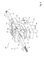
- Fig. 1 shows a transfer device 100 according to the invention for the transfer of press-in elements.
- the press-in elements to be transferred are Nuts M to be subsequently pressed into a sheet metal material.
- the generally designated 100 transfer device comprises a first lower coupling device or coupling unit 200 which is fixed to a lower tool part (a press-bonded sheet metal working tool), and a second upper coupling device or coupling unit 300, which on a likewise not shown tool top (the same sheet metal working tool ) is attached.
- the upper coupling device 300 When moving together or closing the sheet metal working tool, the upper coupling device 300 is lowered vertically in the direction of the fixed lower coupling device 200 (movement according to arrow C in the z-direction), wherein it is for contact between the two coupling devices 200 and 300 or for engagement of the two Coupling devices 200 and 300 comes, as explained in more detail below.
- Denoted by 210 is a feed to the lower coupling device 200, through which the nuts M to be transferred in the transfer device 100 and subsequently to be pressed in are fed in the direction indicated by A from a feed device.
- the feeding takes place in a so-called sliding conveyor, wherein the nuts M abut each other in abutment against each other and form a moving row in the whole.
- the feeder 210 may be a flexible feeder hose connected to the lower coupler 200 by means of a hose coupling 202 configured as a quick coupler.
- a for actuating the quick coupling 202 serving screw mechanism or locking mechanism with helical compression spring and hand lever is off Fig. 3 and Fig. 5 can be seen (see reference numeral 203).
- the discharge 310 designates a removal or removal from the upper coupling device 300, through which the nuts M transferred in the transfer device 100 and subsequently to be pressed in are discharged or removed in the direction indicated by B, the nuts M rising directly up to the tool upper part an injection ram (or to a distribution station) can be further promoted. Again, this is a pushing promotion.
- the discharge 310 may be a flexible hose (or possibly also a rigid pipe) connected to the upper one by means of a coupling coupling 302 Coupling device 300 is connected.
- a for actuating the coupling coupling 302 serving screwing or locking mechanism is made Fig. 3 can be seen (see reference numeral 303).
- the under coupling device 200 has a base block 220, with which the lower coupling device 200 is fixedly attached to the tool lower part (or alternatively also on the press) and which serves as a carrier for the other components of the lower coupling device 200. Furthermore, the lower coupling device 200 has a vertically movable or movable in the z-direction coupling carriage 230 which is biased by a gas pressure spring 240 (or the like) upwards. The gas pressure spring 240 attached to the base block 220 is connected to the coupling carriage 230 via the rod 241.
- the coupling slide 230 When closing the sheet metal working tool (direction C), the coupling slide 230 is moved from the upper coupling device 300 against the force action in the z direction generated by the gas spring 240 to a bottom dead center (UT; Fig. 2 ) moves downwards or downwards.
- the gas spring 240 causes the return of the coupling carriage 230 in the starting position, as in Fig. 1 shown.
- Designated at 235 are two piston-type linear guides for the coupling carriage 230 which are slidably passed through corresponding guide holes in the base plate 220.
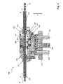
- Fig. 2 shows the transfer device 100 according to the invention in the closed state, wherein the lower coupling device 200 and the upper coupling device 300 are engaged. This results in the overlap between an existing at the lower coupling device 200 transfer channel 215 (see Fig. 3 ) and an existing on the upper coupling means 300 takeover channel 315 (see Fig. 3 ), wherein a passage is provided through which a nut M (or possibly also a plurality of nuts M) can be transferred from the lower coupling device 200 to the upper coupling device 300.
- the transfer device 100 is provided with a first gate valve 250 and associated first gate valve mechanism and with a second gate valve 350 and associated second gate valve mechanism, which will now be described with reference to FIGS Fig. 3 to 7 is explained.
- a first gate valve 250 to prevent the fed through the supply 210 and permanently under delivery pressure nuts M out of the open end of the transfer channel 215 out (the open end of the transfer channel 215 is good in Fig. 1 to recognize).
- the first gate valve 250 is automatically moved from a locked position to a release position.
- Fig. 5 shows the transfer device 100 in the closed state, wherein the first locking slide 250 is in the release position.
- the first gate valve 250 thus serves to block or release the transfer passage 215 on the lower clutch device 200, depending on whether the clutch devices 200 and 300 are engaged or disengaged.
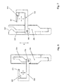
- the first locking slide mechanism is provided which converts the forced movement of the coupling carriage 230 (relative to the basic block 220) during closing and opening of the transfer device 100 into an adjusting movement on the first locking slide 250. This is done in such a way that the first locking slide 250 is automatically moved from the locking position to the release position when closing the transfer device 100 and is automatically moved from the release position into the blocking position when the transfer device 100 is opened.
- the adjusting movements on the first locking slide 250 take place transversely to the conveying direction (A or B) of the nuts M.
- the first gate valve mechanism for actuating the first gate valve 250 includes a fixed control plate 255 with a closed guide groove 256.
- the control board 255 is rigidly secured to the base block 220 (see FIG Fig. 1 ).
- the first locking slide 250 is permanently connected to the guide groove 256 via a rigid first deflection slide 252 and a roller-mounted control roller 253, whereby a positive guide is formed.
- the deflecting slide 252 also serves to hold and guide the first locking slide 250 in the lower coupling device 200. When the first locking slide 250 is moved downwards on the coupling slide 230, the latter is deflected in the lateral direction, which is clearly evident Fig.
- the first locking slide 250 is formed at its front free end with a molded gripping cutout 251, said gripping cutout 251 is located between two gabeizinkenartigen projections with it insertion bevels.
- the contour of the gripping cutout 251 is adapted to the nuts M to be transferred, so that in the transfer channel 215 a nut M "to be transferred can be positively gripped and held by the first blocking slide 250 located in the blocking position, whereby all the nuts M coming from the feeding device are jammed
- the locking of the transfer channel 215 takes place by directly holding a nut M "in this transfer channel 215.
- the parting line between the lower clutch device 200 and the upper clutch device 300 is designated T.
- the second locking slide 250 does not grip the last nut M 'to be transferred next to the parting plane T, but rather the penultimate nut M ", and the first catcher 250 is accordingly arranged and formed penultimate nut M "can be made more reliable than the gripping and holding the last located directly on the parting plane T mother M '. Also structurally, the gripping and holding the penultimate nut M "can be realized more easily.
- a spring pin 216 projecting into the lower coupling device 200 and projecting into the transfer channel 215 is provided last nut M 'with sufficient but not too high strength holds and also against uncontrolled slipping secures (see Fig. 3 ).
- the upper clutch device 300 is equipped with a second gate valve 350.
- the second gate valve 350 serves to release or obstruct the takeover passage 315 on the upper clutch device 300, depending on whether the clutch devices 200 and 300 are engaged or disengaged. As long as the transfer device 100 is in an open state, the second gate valve 350 is in a release position. When closing the transfer device 100, the second gate valve 350 becomes automatic moved from the release position to a locked position.
- Fig. 5 shows the transfer device 100 in the closed state, wherein the second locking slide 350 is in the locked position.
- a second gate valve mechanism is provided which translates the movement of the upper clutch device 300 relative to the lower clutch device 200 (and in particular relative to the base block 220) into an actuating movement on the second gate valve 350. This is done in such a way that the second locking slide 350 is automatically moved from the release position into the blocking position when the transfer device 100 is closed and is automatically moved from the blocking position into the release position when the transfer device 100 is opened.
- the first locking slide 250 on the lower coupling device 200 and the second locking slide 350 on the upper coupling device 300 are therefore actuated automatically in the opposite manner.
- the adjusting movements on the second locking slide 350 take place transversely to the conveying direction (A or B) of the nuts M.
- the second gate valve mechanism for actuating the second gate valve 350 includes a fixed control panel 355 having an upwardly open guide groove 356.
- the control panel 355 is rigidly secured to the base block 220 (see FIG Fig. 1 ).
- the second gate valve 350 can be connected to the guide groove 356 via a rigid second deflecting slide 352 and a roller-mounted control roller 353, whereby a positive guide is brought about.
- the deflecting slide 352 also serves to hold and guide the second locking slide 350 in the upper coupling device 300.
- the control roller 353 held on the deflection slide 352 is inserted from above into the guide groove 356.
- the guide groove 356 is formed at its upper open end with a Ein Industriesschräge 357, which ensures a safe insertion of the control roller 353 regardless of the current position or position of the second locking slide 350 (a biasing of the second locking slide 350 in the release position can be omitted).
- a biasing of the second locking slide 350 in the release position can be omitted.
- the second locking slide 350 is formed at its front end with a molded gripping cutout 351, which is located between two fork-like projections with insertion bevels this gripping cutout 351.
- the contour of the gripping cutout 351 is adapted to the nuts M to be transferred.
- the blocking of the takeover channel 315 does not take place directly at the parting plane T, but rather by a nut length (or by the diameter of a nut M) away from the parting plane T.
- the second gate valve 350 is accordingly arranged and formed.
- the gripping and holding a nut M ** can be done at this point more reliable than the gripping and holding directly on the parting plane T. Also constructive can be the gripping and holding a nut M ** realized at this point easier.
- the fixed nut M ** is aligned so that exactly a transferred nut M * adjoins it without it protruding beyond the parting plane T protrudes from the acceptance channel 315.
- the transfer of a nut M in the transfer device 100 takes place as described below.
- the upper coupling device 300 in the vertical direction z or in the direction the lower coupling device 200 is lowered, as in the Fig. 1 and 3 illustrated by the arrow C.
- the track to be covered from top dead center to bottom dead center of the upper coupling device 300 a multiple of that in the Fig. 1 or Fig. 3 shown vertical distance between the upper coupling device 300 and the lower coupling device 200.
- the first lock slider 250 on the lower clutch device 200 is in the lock position and the second lock slider 350 on the upper clutch device 300 is in the release position.
- a spring pin 316 (or the like) located on the upper coupling device 300 and projecting into the receiving channel 315 prevents the uncontrolled slipping or falling out of nuts M at the open end of the takeover channel 315.
- the coupling plate 330 is fixed to the underside of a base plate 340.
- the gate valves 250 and 350 are actuated, as previously explained.
- the first locking slide 250 is automatically moved to the lower coupling device 200 from the locking position to the release position.
- the second lock slider 350 on the upper clutch device 300 is automatically moved from the release position to the lock position. This change in the slide positions is at the latest at the bottom dead center of the movement (as shown in FIG Fig. 2 and 4 ) and in particular completed before reaching bottom dead center.
- the predetermined by structural design vertical movement distance of the coupling carriage 230 is required for the gate valve operation, wherein the imposed downward movement (and also the subsequent upward movement) by means of the gate valve mechanisms in adjusting movements of the locking slides 250 and 350 is implemented. Further, via the vertical travel distance of the coupling carriage 230, the absolute overlapping time it between the transfer passage 215 in the lower clutch device 200 and the takeover passage 315 in the upper clutch device 300 can be adjusted during the engagement of the clutch devices 200 and 300.
- the next-to-be-transmitted nut M ' may be inserted from the transfer passage 215 into the take-over passage 315, passing through the parting plane T (from left to right).
- the transfer takes place in a horizontal direction (see Fig. 4 ).
- the conveying force required for this purpose is generated by the feeding device.
- the feeding device acts permanently on the nuts M in the feed 210 and in the transfer channel 215 with delivery pressure.
- the insertion of the nut M 'to be transferred into the receiving channel 315 takes place immediately after the first locking slide 250 is moved from its blocking position in the direction of the release position.
- the insertion of the transferring mother M 'in the transfer channel 315 is possible because at this time the space in front of the locking position located in the second locking slide 350 is free or not occupied by a nut M, as explained in more detail below.
- the mother to be handed M ' is pushed to this free space in front of the second locking slide 350 and is thereby to the recorded nut M *.
- the nut M ** held in exact position with the second locking slide 350 ensures that only one nut M * can be received in the transfer channel 350.
- the second locking slide 350 thus acts as a movement stop.
- the vacant by the transfer of the mother M 'space in the transfer channel 215 is immediately replaced by a subsequent nut M, which then forms in the next closing cycle to be transferred mother M'.
- the mother M * received in the transfer channel 315 and the transfer nut 21 'located in the transfer channel 215 and touching the same next to each other directly touch each other in the parting plane T (and stand under delivery pressure).
- This exact positioning is achieved by the held with the second locking slide 350 nut M **.
- the second locking slide 350 as positioning or. Centering slides are called.
- Fig. 5 shows the state after the transfer of the nut M * from the lower coupling device 200 to the upper coupling device 300, wherein the vacated space in the transfer channel 215 of the lower coupling device 200 is already occupied by a retarded or pushed nut M '.
- the upper clutch device 300 may be in bottom dead center together with the clutch carriage 230 (as in FIG Fig. 4 shown).
- the locking slide 250 and 350 arranged on opposite longitudinal sides of the transfer device 100 and are operated according to their arrangement opposite and transverse to the conveying direction A and B respectively.
- the upper coupling device 300 is again moved upwards in the vertical direction.
- the coupling carriage 230 follows this upward movement, which is accomplished by the gas spring 240.
- the first lock slider 250 on the lower clutch device 200 is automatically moved from the release position to the nut M ", substantially simultaneously the second lock slider 350 on the upper clutch device 300 is automatically moved from the lock position to the release position provided that the first locking slide 250 and immediately thereafter or with a time delay, the second locking slide 350 is actuated.
- the upper coupling device 300 from the lower coupling device 200 from, namely then, the coupling carriage 230 has reached its upper end position and its top dead center (which does not correspond to the top dead center of the upper coupling device 300).
- the first locking slide 250 must be in the locked position at the latest when this separation takes place.
- the mother M * taken over into the upper coupling device 300 is moved further in the transfer channel 315.
- the M * of the parting plane T so that at the transfer point again a free space is created, which can be occupied at the next closing of another male nut M *.
- the further movement takes place in conveying direction B, d. H. away from the open end of the transfer channel 315. This further movement is made possible by the previously used or pressed-in nut, whereby a free space has arisen in the discharge channel 310.
- That of the acquired nut M * (or optionally also several nuts taken over) is accomplished by a spring-loaded latch mechanism in the upper coupling device 300, as explained in more detail below.
- the pawl mechanism in the upper coupling device 300 includes a linearly movable pawl slider 360, as very good Fig. 3 seen.
- the pawl slide 360 is mounted substantially horizontally movable back and forth in the upper coupling device 300 and is acted upon by a gas spring 363 directly and permanently with a force.
- With 370 is a housing block or a slider housing for receiving the pawl slide 360 and 371 is a housing cover
- a slot 372 is formed, as shown in the Fig. 1 and 2 seen.
- the compressive force generated by the gas pressure spring 363 forces the pawl slide 360 in the conveying direction B, wherein arranged on the pawl slide 360 latch hook 361 the last or last taken mother M * in the transfer channel 315 engages behind and thus all located in the transfer channel 315 and in the discharge 310 and pushes against each other abutting nuts M and keeps under delivery pressure, but this can only take place when the second gate valve 350 is no longer in the locked position.
- the last adopted mother M * in the conveying direction B is moved away from the parting plane T, whereby at the open end of the transfer channel 315 again a free space for subsequent reception of another nut M * is created.
- the pawl hook 361 prevents nuts M from falling out of the open end of the takeover channel 315.
- An additional backup is given by the spring pin 316, as already explained.
- the pawl slider 360 After the pawl slider 360 has moved on or moved on the last taken over nut M *, it must again be moved back into an initial position against the pressure force generated by the gas spring 363 in order to grip the next taken over nut M * and to be able to continue in the conveying direction B.
- the backward movement of the pawl slider 360 in the starting position is at Closing the transfer device 100 accomplished by a setting mechanism or remindstellstellmechanismus, as explained below.
- the actuating mechanism for resetting the pawl slide 360 comprises two rocker arms 366, which are pivotally mounted on the upper coupling device 300 via pivot joints 365 (see FIG Fig. 1 ). At their lower free ends, the rocker arms 366 are connected to a transverse bolt 367. At their upper free ends, the rocker arms 366 are in contact with pins 369, which are fastened laterally to the pawl slide 360 and guided outward by guide grooves 373 in the housing block 370.
- the rocker arm 366 When closing the transfer device 100, the rocker arm 366 are pivoted and in this case push back the pawl slide 360 via the pins 369 against the force action by the gas spring 363.
- the pivoting of the rocker arms 366 when closing the transfer device 100 is effected by fixed guide plates 260 on the lower coupling device 200.
- the guide plates 260 are formed with inclined sliding surfaces 261, on which the transverse bolt 367 slides during the downward movement of the upper coupling device 300 and is thereby successively pushed away or deflected.
- rolling bearings or driving rollers 368 are provided.
- roller bearings or drive rollers can be provided. The required for the pushing back of the pawl slide 360 and / or the required force can be adjusted by design of leverage, angle and / or travel conditions.
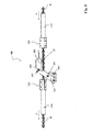
- Fig. 8 shows the state in the bottom dead center, wherein the pressure force generated by the gas spring 363 in Fig. 8 is illustrated with an arrow F.
- the pawl hook 361 is resiliently connected in the vertical direction with the pawl slide 360 and is biased by a spring 362 down.
- the nut to be handed M 'or M * push the pawl 361 against the effective spring force upwards, including the pawl 361 is formed at its lower end with a sliding bevel.
- the mother M 'or M * to be handed over has passed the pawl hook 361, it springs back downwards and engages behind the assumed nut M *, which in this way is also held in the takeover channel 315.
- the gas spring 363 can exert no effective pressure force on the pawl slide 360 and the pawl hook 361. Only when the upward movement of the upper coupling device 300, the gas spring 363 successively build up their pressure force, which is initially still ineffective until the second locking slide 350 has been moved from its locked position to the release position.
- the transfer device 100 according to the invention is characterized by a compact construction. Furthermore, the transfer mechanism is largely encapsulated and thus protected against contamination and external interference.
- the transfer device 100 according to the invention can also be designed for a sequence of movements other than those explained above, for example such that the clutch device 200 moves upwards or both clutch devices are moved simultaneously, and so on.
- Transfer device for the sliding transfer of press-in elements on a sheet metal working tool and sheet metal working tool with such a transfer device
Landscapes
- Engineering & Computer Science (AREA)
- Mechanical Engineering (AREA)
- Press Drives And Press Lines (AREA)
Applications Claiming Priority (1)
| Application Number | Priority Date | Filing Date | Title |
|---|---|---|---|
| DE102012202597A DE102012202597A1 (de) | 2012-02-21 | 2012-02-21 | Übergabevorrichtung für die schiebende Übergabe von Einpresselementen an einem Blechbearbeitungswerkzeug und Blechbearbeitungswerkzeug mit einer solchen Übergabevorrichtung |
Publications (3)
| Publication Number | Publication Date |
|---|---|
| EP2631031A2 true EP2631031A2 (fr) | 2013-08-28 |
| EP2631031A3 EP2631031A3 (fr) | 2017-11-29 |
| EP2631031B1 EP2631031B1 (fr) | 2022-08-24 |
Family
ID=47561382
Family Applications (1)
| Application Number | Title | Priority Date | Filing Date |
|---|---|---|---|
| EP13151132.1A Active EP2631031B1 (fr) | 2012-02-21 | 2013-01-14 | Dispositif de transfert pour le transfert en propulsion d'éléments de compression sur un outil de traitement de tôle et outil de traitement de tôle doté d'un tel dispositif de transfert |
Country Status (2)
| Country | Link |
|---|---|
| EP (1) | EP2631031B1 (fr) |
| DE (1) | DE102012202597A1 (fr) |
Cited By (8)
| Publication number | Priority date | Publication date | Assignee | Title |
|---|---|---|---|---|
| CN107457547A (zh) * | 2017-08-02 | 2017-12-12 | 深圳市众创立科技有限公司 | 一种铜针送料装置 |
| CN112077577A (zh) * | 2020-09-13 | 2020-12-15 | 钱水祥 | 一种用于金属撬刀的壳体自动装配系统 |
| EP3907017A1 (fr) * | 2020-05-06 | 2021-11-10 | Newfrey LLC | Dispositif de fixation, système avec dispositif de fixation et procédé d'alimentation de fixations |
| CN114375737A (zh) * | 2020-10-03 | 2022-04-22 | 谢晓兵 | 一种幼果套袋机封口装置及一种封口方法 |
| CN114654232A (zh) * | 2022-04-08 | 2022-06-24 | 无锡市神力齿轮冷挤有限公司 | 一种汽车单向离合器定套组装设备 |
| CN114850851A (zh) * | 2022-05-23 | 2022-08-05 | 李卯香 | 一种钣金加工用螺母压铆机 |
| CN116424842A (zh) * | 2023-02-11 | 2023-07-14 | 华朔科技(宁波鄞州)有限公司 | 一种用于新能源汽车零件的钢珠自动上料机构及组装装置 |
| CN121179183A (zh) * | 2025-11-24 | 2025-12-23 | 中国电器科学研究院股份有限公司 | 一种冰箱背板压装装置 |
Citations (3)
| Publication number | Priority date | Publication date | Assignee | Title |
|---|---|---|---|---|
| DE4422708A1 (de) | 1993-12-17 | 1995-11-16 | Schmidt Dieter Maschbau | Vorrichtung zur Verwendung in einer Presse zum Zuführen von Verbindungselementen und deren Befestigung in Werkstücken durch Verpressen |
| DE19709714A1 (de) | 1997-03-10 | 1998-09-17 | Profil Verbindungstechnik Gmbh | Versorgungssystem zur Lieferung von Elementen an Abnehmer sowie Verfahren zur Versorgung eines Abnehmers |
| DE19823040A1 (de) | 1998-05-22 | 1999-11-25 | Profil Verbindungstechnik Gmbh | Verfahren und Vorrichtung zur Übergabe von Befestigungselementen an Stanzköpfe |
Family Cites Families (1)
| Publication number | Priority date | Publication date | Assignee | Title |
|---|---|---|---|---|
| DE4340642A1 (de) * | 1993-11-29 | 1995-06-01 | Schmidt Dieter Maschbau | Vorrichtung zur Verwendung in einer Presse zum Zuführen von Verbindungselementen und zu deren Befestigung in Werkstücken durch Verpressen |
-
2012
- 2012-02-21 DE DE102012202597A patent/DE102012202597A1/de not_active Withdrawn
-
2013
- 2013-01-14 EP EP13151132.1A patent/EP2631031B1/fr active Active
Patent Citations (3)
| Publication number | Priority date | Publication date | Assignee | Title |
|---|---|---|---|---|
| DE4422708A1 (de) | 1993-12-17 | 1995-11-16 | Schmidt Dieter Maschbau | Vorrichtung zur Verwendung in einer Presse zum Zuführen von Verbindungselementen und deren Befestigung in Werkstücken durch Verpressen |
| DE19709714A1 (de) | 1997-03-10 | 1998-09-17 | Profil Verbindungstechnik Gmbh | Versorgungssystem zur Lieferung von Elementen an Abnehmer sowie Verfahren zur Versorgung eines Abnehmers |
| DE19823040A1 (de) | 1998-05-22 | 1999-11-25 | Profil Verbindungstechnik Gmbh | Verfahren und Vorrichtung zur Übergabe von Befestigungselementen an Stanzköpfe |
Cited By (10)
| Publication number | Priority date | Publication date | Assignee | Title |
|---|---|---|---|---|
| CN107457547A (zh) * | 2017-08-02 | 2017-12-12 | 深圳市众创立科技有限公司 | 一种铜针送料装置 |
| EP3907017A1 (fr) * | 2020-05-06 | 2021-11-10 | Newfrey LLC | Dispositif de fixation, système avec dispositif de fixation et procédé d'alimentation de fixations |
| CN112077577A (zh) * | 2020-09-13 | 2020-12-15 | 钱水祥 | 一种用于金属撬刀的壳体自动装配系统 |
| CN114375737A (zh) * | 2020-10-03 | 2022-04-22 | 谢晓兵 | 一种幼果套袋机封口装置及一种封口方法 |
| CN114654232A (zh) * | 2022-04-08 | 2022-06-24 | 无锡市神力齿轮冷挤有限公司 | 一种汽车单向离合器定套组装设备 |
| CN114654232B (zh) * | 2022-04-08 | 2023-07-25 | 无锡市神力齿轮冷挤有限公司 | 一种汽车单向离合器定套组装设备 |
| CN114850851A (zh) * | 2022-05-23 | 2022-08-05 | 李卯香 | 一种钣金加工用螺母压铆机 |
| CN114850851B (zh) * | 2022-05-23 | 2024-05-24 | 广州市高比电梯装饰工程有限公司 | 一种钣金加工用螺母压铆机 |
| CN116424842A (zh) * | 2023-02-11 | 2023-07-14 | 华朔科技(宁波鄞州)有限公司 | 一种用于新能源汽车零件的钢珠自动上料机构及组装装置 |
| CN121179183A (zh) * | 2025-11-24 | 2025-12-23 | 中国电器科学研究院股份有限公司 | 一种冰箱背板压装装置 |
Also Published As
| Publication number | Publication date |
|---|---|
| DE102012202597A1 (de) | 2013-08-22 |
| EP2631031B1 (fr) | 2022-08-24 |
| EP2631031A3 (fr) | 2017-11-29 |
Similar Documents
| Publication | Publication Date | Title |
|---|---|---|
| EP2631031B1 (fr) | Dispositif de transfert pour le transfert en propulsion d'éléments de compression sur un outil de traitement de tôle et outil de traitement de tôle doté d'un tel dispositif de transfert | |
| DE4211276C2 (de) | Haltevorrichtung zum Halten, Führen und Freigeben eines Fügeteils, wie z.B. einer Mutter | |
| EP2424712B1 (fr) | Élément de saisie de produit | |
| DE102009049616B4 (de) | Setzgerät, Zuführmodul des Setzgeräts und Fügeverfahren zum Verbinden von mindestens zwei Bauteilen | |
| EP0633825B1 (fr) | Dispositif d'amenee de pieces d'assemblage | |
| DE1782885B1 (de) | Vorrichtung zum Aufsetzen des Schiebers und der oberen Endglieder auf verkonfektionierte gekuppelte Reissverschluesse | |
| DE1915159B2 (de) | Vorrichtung zum Einsetzen elektrischer Bauelemente in eine Leiterplatte | |
| DE4008515A1 (de) | Hand-pressgeraet | |
| DE4415973C2 (de) | Vorrichtung zur Verwendung in einer Presse zum Zuführen von Verbindungselementen und zu deren Befestigung in Werkstücken durch Verpressen | |
| EP3302875B1 (fr) | Dispositif et procédé de positionnement d'éléments de fixation | |
| EP2794142B1 (fr) | Matrice d'un dispositif de poinçonnage et procédé de poinçonnage | |
| EP0755749B1 (fr) | Dispositif de guidage et/ou de fixation pour éléments, particulièrement pour éléments de fixation | |
| DE102019008679A1 (de) | Montagevorrichtung | |
| DE1026389B (de) | Werkzeug zum Kerben elektrischer Leitungsverbinder | |
| DE1955193A1 (de) | Verfahren und Vorrichtung zum Werkzeugwechsel an einer Maschine mit hin- und hergehender Arbeitsbewegung | |
| EP1839803A1 (fr) | Insertion de boulons | |
| DE2028315A1 (de) | Vorrichtung und Verfahren zum Einsetzen von stiftförmigen Kontakt stucken in Schalttafeln, Klemmleisten oder dergl | |
| EP1079952B1 (fr) | Procede et dispositif pour le transfert d'elements de fixation a des tetes de pression | |
| DE2360947B2 (de) | Vorrichtung zum Ausrichten einer Gruppe von Kuppelgliedern einer ReißverschluBkette | |
| DE2259921C2 (de) | Maschine zum Abtrennen der Anschlußklemmen von einem Trägerstreifen | |
| DE4422708B4 (de) | Vorrichtung zur Verwendung in einer Presse zum Zuführen von Verbindungselementen und deren Befestigung in Werkstücken durch Verpressen | |
| DE3342348A1 (de) | Vorrichtung und verfahren zur zufuhr und foerderung elektronischer bauteile | |
| EP0109094B1 (fr) | Dispositif pour fabriquer des empilages de tôles | |
| DE202019005114U1 (de) | Montagevorrichtung | |
| EP0725702A1 (fr) | Dispositif s'utilisant dans une presse pour acheminer des elements d'assemblage et pour les fixer par pression dans des pieces |
Legal Events
| Date | Code | Title | Description |
|---|---|---|---|
| PUAI | Public reference made under article 153(3) epc to a published international application that has entered the european phase |
Free format text: ORIGINAL CODE: 0009012 |
|
| AK | Designated contracting states |
Kind code of ref document: A2 Designated state(s): AL AT BE BG CH CY CZ DE DK EE ES FI FR GB GR HR HU IE IS IT LI LT LU LV MC MK MT NL NO PL PT RO RS SE SI SK SM TR |
|
| AX | Request for extension of the european patent |
Extension state: BA ME |
|
| RAP1 | Party data changed (applicant data changed or rights of an application transferred) |
Owner name: BAYERISCHE MOTOREN WERKE AKTIENGESELLSCHAFT |
|
| PUAL | Search report despatched |
Free format text: ORIGINAL CODE: 0009013 |
|
| AK | Designated contracting states |
Kind code of ref document: A3 Designated state(s): AL AT BE BG CH CY CZ DE DK EE ES FI FR GB GR HR HU IE IS IT LI LT LU LV MC MK MT NL NO PL PT RO RS SE SI SK SM TR |
|
| AX | Request for extension of the european patent |
Extension state: BA ME |
|
| RIC1 | Information provided on ipc code assigned before grant |
Ipc: B23P 19/00 20060101AFI20171026BHEP Ipc: B21J 15/32 20060101ALI20171026BHEP Ipc: B23P 19/06 20060101ALI20171026BHEP |
|
| 17P | Request for examination filed |
Effective date: 20180425 |
|
| RBV | Designated contracting states (corrected) |
Designated state(s): AL AT BE BG CH CY CZ DE DK EE ES FI FR GB GR HR HU IE IS IT LI LT LU LV MC MK MT NL NO PL PT RO RS SE SI SK SM TR |
|
| STAA | Information on the status of an ep patent application or granted ep patent |
Free format text: STATUS: EXAMINATION IS IN PROGRESS |
|
| 17Q | First examination report despatched |
Effective date: 20210521 |
|
| GRAP | Despatch of communication of intention to grant a patent |
Free format text: ORIGINAL CODE: EPIDOSNIGR1 |
|
| STAA | Information on the status of an ep patent application or granted ep patent |
Free format text: STATUS: GRANT OF PATENT IS INTENDED |
|
| INTG | Intention to grant announced |
Effective date: 20220509 |
|
| GRAS | Grant fee paid |
Free format text: ORIGINAL CODE: EPIDOSNIGR3 |
|
| GRAA | (expected) grant |
Free format text: ORIGINAL CODE: 0009210 |
|
| STAA | Information on the status of an ep patent application or granted ep patent |
Free format text: STATUS: THE PATENT HAS BEEN GRANTED |
|
| AK | Designated contracting states |
Kind code of ref document: B1 Designated state(s): AL AT BE BG CH CY CZ DE DK EE ES FI FR GB GR HR HU IE IS IT LI LT LU LV MC MK MT NL NO PL PT RO RS SE SI SK SM TR |
|
| REG | Reference to a national code |
Ref country code: GB Ref legal event code: FG4D Free format text: NOT ENGLISH |
|
| REG | Reference to a national code |
Ref country code: CH Ref legal event code: EP |
|
| REG | Reference to a national code |
Ref country code: DE Ref legal event code: R096 Ref document number: 502013016219 Country of ref document: DE |
|
| REG | Reference to a national code |
Ref country code: IE Ref legal event code: FG4D Free format text: LANGUAGE OF EP DOCUMENT: GERMAN |
|
| REG | Reference to a national code |
Ref country code: AT Ref legal event code: REF Ref document number: 1513310 Country of ref document: AT Kind code of ref document: T Effective date: 20220915 |
|
| REG | Reference to a national code |
Ref country code: LT Ref legal event code: MG9D |
|
| REG | Reference to a national code |
Ref country code: NL Ref legal event code: MP Effective date: 20220824 |
|
| PG25 | Lapsed in a contracting state [announced via postgrant information from national office to epo] |
Ref country code: SE Free format text: LAPSE BECAUSE OF FAILURE TO SUBMIT A TRANSLATION OF THE DESCRIPTION OR TO PAY THE FEE WITHIN THE PRESCRIBED TIME-LIMIT Effective date: 20220824 Ref country code: RS Free format text: LAPSE BECAUSE OF FAILURE TO SUBMIT A TRANSLATION OF THE DESCRIPTION OR TO PAY THE FEE WITHIN THE PRESCRIBED TIME-LIMIT Effective date: 20220824 Ref country code: PT Free format text: LAPSE BECAUSE OF FAILURE TO SUBMIT A TRANSLATION OF THE DESCRIPTION OR TO PAY THE FEE WITHIN THE PRESCRIBED TIME-LIMIT Effective date: 20221226 Ref country code: NO Free format text: LAPSE BECAUSE OF FAILURE TO SUBMIT A TRANSLATION OF THE DESCRIPTION OR TO PAY THE FEE WITHIN THE PRESCRIBED TIME-LIMIT Effective date: 20221124 Ref country code: NL Free format text: LAPSE BECAUSE OF FAILURE TO SUBMIT A TRANSLATION OF THE DESCRIPTION OR TO PAY THE FEE WITHIN THE PRESCRIBED TIME-LIMIT Effective date: 20220824 Ref country code: LV Free format text: LAPSE BECAUSE OF FAILURE TO SUBMIT A TRANSLATION OF THE DESCRIPTION OR TO PAY THE FEE WITHIN THE PRESCRIBED TIME-LIMIT Effective date: 20220824 Ref country code: LT Free format text: LAPSE BECAUSE OF FAILURE TO SUBMIT A TRANSLATION OF THE DESCRIPTION OR TO PAY THE FEE WITHIN THE PRESCRIBED TIME-LIMIT Effective date: 20220824 Ref country code: FI Free format text: LAPSE BECAUSE OF FAILURE TO SUBMIT A TRANSLATION OF THE DESCRIPTION OR TO PAY THE FEE WITHIN THE PRESCRIBED TIME-LIMIT Effective date: 20220824 Ref country code: ES Free format text: LAPSE BECAUSE OF FAILURE TO SUBMIT A TRANSLATION OF THE DESCRIPTION OR TO PAY THE FEE WITHIN THE PRESCRIBED TIME-LIMIT Effective date: 20220824 |
|
| PG25 | Lapsed in a contracting state [announced via postgrant information from national office to epo] |
Ref country code: PL Free format text: LAPSE BECAUSE OF FAILURE TO SUBMIT A TRANSLATION OF THE DESCRIPTION OR TO PAY THE FEE WITHIN THE PRESCRIBED TIME-LIMIT Effective date: 20220824 Ref country code: IS Free format text: LAPSE BECAUSE OF FAILURE TO SUBMIT A TRANSLATION OF THE DESCRIPTION OR TO PAY THE FEE WITHIN THE PRESCRIBED TIME-LIMIT Effective date: 20221224 Ref country code: HR Free format text: LAPSE BECAUSE OF FAILURE TO SUBMIT A TRANSLATION OF THE DESCRIPTION OR TO PAY THE FEE WITHIN THE PRESCRIBED TIME-LIMIT Effective date: 20220824 Ref country code: GR Free format text: LAPSE BECAUSE OF FAILURE TO SUBMIT A TRANSLATION OF THE DESCRIPTION OR TO PAY THE FEE WITHIN THE PRESCRIBED TIME-LIMIT Effective date: 20221125 |
|
| PG25 | Lapsed in a contracting state [announced via postgrant information from national office to epo] |
Ref country code: SM Free format text: LAPSE BECAUSE OF FAILURE TO SUBMIT A TRANSLATION OF THE DESCRIPTION OR TO PAY THE FEE WITHIN THE PRESCRIBED TIME-LIMIT Effective date: 20220824 Ref country code: RO Free format text: LAPSE BECAUSE OF FAILURE TO SUBMIT A TRANSLATION OF THE DESCRIPTION OR TO PAY THE FEE WITHIN THE PRESCRIBED TIME-LIMIT Effective date: 20220824 Ref country code: DK Free format text: LAPSE BECAUSE OF FAILURE TO SUBMIT A TRANSLATION OF THE DESCRIPTION OR TO PAY THE FEE WITHIN THE PRESCRIBED TIME-LIMIT Effective date: 20220824 Ref country code: CZ Free format text: LAPSE BECAUSE OF FAILURE TO SUBMIT A TRANSLATION OF THE DESCRIPTION OR TO PAY THE FEE WITHIN THE PRESCRIBED TIME-LIMIT Effective date: 20220824 |
|
| REG | Reference to a national code |
Ref country code: DE Ref legal event code: R097 Ref document number: 502013016219 Country of ref document: DE |
|
| PG25 | Lapsed in a contracting state [announced via postgrant information from national office to epo] |
Ref country code: SK Free format text: LAPSE BECAUSE OF FAILURE TO SUBMIT A TRANSLATION OF THE DESCRIPTION OR TO PAY THE FEE WITHIN THE PRESCRIBED TIME-LIMIT Effective date: 20220824 Ref country code: EE Free format text: LAPSE BECAUSE OF FAILURE TO SUBMIT A TRANSLATION OF THE DESCRIPTION OR TO PAY THE FEE WITHIN THE PRESCRIBED TIME-LIMIT Effective date: 20220824 |
|
| P01 | Opt-out of the competence of the unified patent court (upc) registered |
Effective date: 20230502 |
|
| PG25 | Lapsed in a contracting state [announced via postgrant information from national office to epo] |
Ref country code: AL Free format text: LAPSE BECAUSE OF FAILURE TO SUBMIT A TRANSLATION OF THE DESCRIPTION OR TO PAY THE FEE WITHIN THE PRESCRIBED TIME-LIMIT Effective date: 20220824 |
|
| PLBE | No opposition filed within time limit |
Free format text: ORIGINAL CODE: 0009261 |
|
| STAA | Information on the status of an ep patent application or granted ep patent |
Free format text: STATUS: NO OPPOSITION FILED WITHIN TIME LIMIT |
|
| 26N | No opposition filed |
Effective date: 20230525 |
|
| PG25 | Lapsed in a contracting state [announced via postgrant information from national office to epo] |
Ref country code: SI Free format text: LAPSE BECAUSE OF FAILURE TO SUBMIT A TRANSLATION OF THE DESCRIPTION OR TO PAY THE FEE WITHIN THE PRESCRIBED TIME-LIMIT Effective date: 20220824 |
|
| REG | Reference to a national code |
Ref country code: CH Ref legal event code: PL |
|
| PG25 | Lapsed in a contracting state [announced via postgrant information from national office to epo] |
Ref country code: LU Free format text: LAPSE BECAUSE OF NON-PAYMENT OF DUE FEES Effective date: 20230114 |
|
| REG | Reference to a national code |
Ref country code: BE Ref legal event code: MM Effective date: 20230131 |
|
| PG25 | Lapsed in a contracting state [announced via postgrant information from national office to epo] |
Ref country code: LI Free format text: LAPSE BECAUSE OF NON-PAYMENT OF DUE FEES Effective date: 20230131 Ref country code: CH Free format text: LAPSE BECAUSE OF NON-PAYMENT OF DUE FEES Effective date: 20230131 |
|
| PG25 | Lapsed in a contracting state [announced via postgrant information from national office to epo] |
Ref country code: BE Free format text: LAPSE BECAUSE OF NON-PAYMENT OF DUE FEES Effective date: 20230131 |
|
| PG25 | Lapsed in a contracting state [announced via postgrant information from national office to epo] |
Ref country code: IE Free format text: LAPSE BECAUSE OF NON-PAYMENT OF DUE FEES Effective date: 20230114 |
|
| REG | Reference to a national code |
Ref country code: AT Ref legal event code: MM01 Ref document number: 1513310 Country of ref document: AT Kind code of ref document: T Effective date: 20230114 |
|
| PG25 | Lapsed in a contracting state [announced via postgrant information from national office to epo] |
Ref country code: AT Free format text: LAPSE BECAUSE OF NON-PAYMENT OF DUE FEES Effective date: 20230114 |
|
| PG25 | Lapsed in a contracting state [announced via postgrant information from national office to epo] |
Ref country code: AT Free format text: LAPSE BECAUSE OF NON-PAYMENT OF DUE FEES Effective date: 20230114 |
|
| PG25 | Lapsed in a contracting state [announced via postgrant information from national office to epo] |
Ref country code: IT Free format text: LAPSE BECAUSE OF FAILURE TO SUBMIT A TRANSLATION OF THE DESCRIPTION OR TO PAY THE FEE WITHIN THE PRESCRIBED TIME-LIMIT Effective date: 20220824 |
|
| PG25 | Lapsed in a contracting state [announced via postgrant information from national office to epo] |
Ref country code: MC Free format text: LAPSE BECAUSE OF FAILURE TO SUBMIT A TRANSLATION OF THE DESCRIPTION OR TO PAY THE FEE WITHIN THE PRESCRIBED TIME-LIMIT Effective date: 20220824 |
|
| PG25 | Lapsed in a contracting state [announced via postgrant information from national office to epo] |
Ref country code: MC Free format text: LAPSE BECAUSE OF FAILURE TO SUBMIT A TRANSLATION OF THE DESCRIPTION OR TO PAY THE FEE WITHIN THE PRESCRIBED TIME-LIMIT Effective date: 20220824 |
|
| PG25 | Lapsed in a contracting state [announced via postgrant information from national office to epo] |
Ref country code: BG Free format text: LAPSE BECAUSE OF FAILURE TO SUBMIT A TRANSLATION OF THE DESCRIPTION OR TO PAY THE FEE WITHIN THE PRESCRIBED TIME-LIMIT Effective date: 20220824 |
|
| PG25 | Lapsed in a contracting state [announced via postgrant information from national office to epo] |
Ref country code: BG Free format text: LAPSE BECAUSE OF FAILURE TO SUBMIT A TRANSLATION OF THE DESCRIPTION OR TO PAY THE FEE WITHIN THE PRESCRIBED TIME-LIMIT Effective date: 20220824 |
|
| PG25 | Lapsed in a contracting state [announced via postgrant information from national office to epo] |
Ref country code: CY Free format text: LAPSE BECAUSE OF FAILURE TO SUBMIT A TRANSLATION OF THE DESCRIPTION OR TO PAY THE FEE WITHIN THE PRESCRIBED TIME-LIMIT; INVALID AB INITIO Effective date: 20130114 |
|
| PG25 | Lapsed in a contracting state [announced via postgrant information from national office to epo] |
Ref country code: HU Free format text: LAPSE BECAUSE OF FAILURE TO SUBMIT A TRANSLATION OF THE DESCRIPTION OR TO PAY THE FEE WITHIN THE PRESCRIBED TIME-LIMIT; INVALID AB INITIO Effective date: 20130114 |
|
| PG25 | Lapsed in a contracting state [announced via postgrant information from national office to epo] |
Ref country code: TR Free format text: LAPSE BECAUSE OF FAILURE TO SUBMIT A TRANSLATION OF THE DESCRIPTION OR TO PAY THE FEE WITHIN THE PRESCRIBED TIME-LIMIT Effective date: 20220824 |
|
| PGFP | Annual fee paid to national office [announced via postgrant information from national office to epo] |
Ref country code: GB Payment date: 20260122 Year of fee payment: 14 |
|
| PGFP | Annual fee paid to national office [announced via postgrant information from national office to epo] |
Ref country code: DE Payment date: 20260121 Year of fee payment: 14 |
|
| PGFP | Annual fee paid to national office [announced via postgrant information from national office to epo] |
Ref country code: FR Payment date: 20260123 Year of fee payment: 14 |