EP2631100A2 - Dispositif de porte coulissante avec rail de guidage oblique - Google Patents
Dispositif de porte coulissante avec rail de guidage oblique Download PDFInfo
- Publication number
- EP2631100A2 EP2631100A2 EP13155611.0A EP13155611A EP2631100A2 EP 2631100 A2 EP2631100 A2 EP 2631100A2 EP 13155611 A EP13155611 A EP 13155611A EP 2631100 A2 EP2631100 A2 EP 2631100A2
- Authority
- EP
- European Patent Office
- Prior art keywords
- sliding door
- guide rail
- connecting means
- door device
- vertical
- Prior art date
- Legal status (The legal status is an assumption and is not a legal conclusion. Google has not performed a legal analysis and makes no representation as to the accuracy of the status listed.)
- Withdrawn
Links
- 238000006073 displacement reaction Methods 0.000 claims abstract description 20
- 238000010586 diagram Methods 0.000 description 2
- 238000012986 modification Methods 0.000 description 2
- 230000004048 modification Effects 0.000 description 2
- 238000009420 retrofitting Methods 0.000 description 2
- 238000006243 chemical reaction Methods 0.000 description 1
- 238000005352 clarification Methods 0.000 description 1
- 230000008878 coupling Effects 0.000 description 1
- 238000010168 coupling process Methods 0.000 description 1
- 238000005859 coupling reaction Methods 0.000 description 1
- 239000000428 dust Substances 0.000 description 1
- 238000005516 engineering process Methods 0.000 description 1
- XLYOFNOQVPJJNP-UHFFFAOYSA-N water Substances O XLYOFNOQVPJJNP-UHFFFAOYSA-N 0.000 description 1
Images

Classifications
-
- B—PERFORMING OPERATIONS; TRANSPORTING
- B60—VEHICLES IN GENERAL
- B60J—WINDOWS, WINDSCREENS, NON-FIXED ROOFS, DOORS, OR SIMILAR DEVICES FOR VEHICLES; REMOVABLE EXTERNAL PROTECTIVE COVERINGS SPECIALLY ADAPTED FOR VEHICLES
- B60J5/00—Doors
- B60J5/04—Doors arranged at the vehicle sides
- B60J5/06—Doors arranged at the vehicle sides slidable; foldable
- B60J5/062—Doors arranged at the vehicle sides slidable; foldable for utility vehicles or public transport
-
- B—PERFORMING OPERATIONS; TRANSPORTING
- B60—VEHICLES IN GENERAL
- B60J—WINDOWS, WINDSCREENS, NON-FIXED ROOFS, DOORS, OR SIMILAR DEVICES FOR VEHICLES; REMOVABLE EXTERNAL PROTECTIVE COVERINGS SPECIALLY ADAPTED FOR VEHICLES
- B60J5/00—Doors
- B60J5/04—Doors arranged at the vehicle sides
- B60J5/047—Doors arranged at the vehicle sides characterised by the opening or closing movement
Definitions
- sliding door devices are known in particular in vehicle technology and are often used in commercial vehicles.
- the sliding door is moved by these motor or by manual pushing or pulling the door leaf.
- the sliding door is moved along its displacement path substantially parallel to the body wall of the vehicle outside.
- the door opening is usually arranged between the wheel axles.
- the door opening is usually arranged between the wheel axles.
- the sliding door When the sliding door is opened and moved backwards, it conceals the rear wheel of the vehicle, especially for vehicles with a short wheelbase, as seen from the side.
- a major problem arises when the rear wheel protrudes outward beyond the body panel of the vehicle. In this case, or even if other parts of the vehicle protrude into the displacement path of the sliding door, complex and costly holding and displacement devices for the sliding door are necessary.
- this describes DE 10 2008 058 242 A1 a sliding door assembly that allows the sliding door to swing out to pass obstacles. This is made possible by a complex joint in a coupling means between the sliding door and a guide rail. Through this hinge, the door can be swung away from the body wall when moving backwards.
- the object of the invention is to provide a simple and inexpensive sliding door device, especially for vehicles, the one Moving the sliding door substantially parallel to a body wall allows even if obstacles protrude into the displacement of the sliding door.
- this is characterized in that the guide rails are arranged in a horizontal plane or relative to a transverse axis of the vehicle so inclined to each other, that the sliding door, starting from a closed position in the direction of an open position increasingly oblique to a vertical.
- a guide rail runs approximately parallel to the body outer wall of the vehicle or parallel to an upper or lower closing edge of the sliding door, the other guide rail, however, obliquely to the body outer wall of the vehicle or the upper or lower closing edge of the sliding door.
- the upper and closing edge respectively means that edge which runs generally parallel to the closing direction, by “bottom” the closing edge is meant, which, installed in the motor vehicle, is arranged closer to the road surface.
- the sliding door according to the invention is particularly suitable as vehicle sliding doors, but the idea is also feasible for windows, flaps or the like.
- the term sliding door includes according to the invention corresponding elements.
- the sliding door closes in the open position, starting from the first guide rail according to the invention an angle of 0.5 ° to 10 °, preferably 3 to 5 °, in particular 1.6 °. In particular, an angle of less than 5 ° is common for standard delivery vehicles, which typically have a height between 1.8 m and 2.8 m. already sufficient, for example, to pass the sliding door on a laterally projecting rear wheel. An angle of 1.2 ° to 2 °, in particular 1.6 ° has proven to be particularly suitable for these vehicles.
- the first guide rail can in principle be arranged below or above the second guide rail in the vertical direction, but in a particularly advantageous embodiment, the first guide rail is arranged in the vertical direction above the second, obliquely arranged guide rail.
- the lower closing edge of the sliding door is therefore objected to in the open position of the body outer wall, while the upper closing edge of the sliding door is held over its entire length close to the body wall.
- the upper first guide rail may be formed as a U-profile, in which the sliding door is mounted and guided hanging over the first connecting means and a roller arranged thereon.
- the U-profile is arranged open at the top, the wheel axle of the roller is transverse to the longitudinal direction of the first guide rail.
- the roller and the U-profile are matched to one another such that pivoting of the sliding door transversely to the longitudinal direction of the first guide rail or from the vertical is possible.
- the pivoting of the sliding door transversely to the longitudinal direction of the first guide rail is necessary because the sliding door is forcibly pivoted out of the vertical due to the inclined second guide rail via the displacement and must not be blocked by the first or upper guide rail.
- the connecting means may have joints or the rollers may have corresponding pivotal ball joints.
- the sliding door per guide rail has a plurality of connecting means, which are arranged one behind the other in the direction of displacement of the sliding door. This ensures that the sliding door is held better and more stable in the body outer wall.
- the connecting means preferably have different lengths.
- the length of the connecting means may preferably be chosen such that they compensate for the inclination of the second guide rail in the longitudinal direction, that is, for example, with respect to the body outer wall of the vehicle, along the displacement. This means, that the sliding door and thus also the upper and / or lower closing edges is always aligned parallel to the body outer wall regardless of their position.
- the sliding door is thus set during the opening operation with respect to the vertical while inclined, with respect to a longitudinal axis of the vehicle, which generally corresponds to the direction of displacement, but it remains aligned in parallel ,
- the sliding door is mounted only linearly displaceable. Due to the lack of pivot joints, the assembly unit according to the invention is light and prone to failure. Furthermore, the gaps remaining at the closed position of the door leaf between the door leaf and the door frame are comparatively easy to seal against the ingress of dust, dirt and water.
- the invention is particularly suitable for training as a mounting unit, which also has a corresponding door frame and can be used in a door opening of a body outer wall.
- the mounting unit has all the necessary components to allow opening and closing of the sliding door.
- Assembly unit according to the invention means that the vehicle sliding door device is a separate from the body of the vehicle, independent component. Thus, on the part of the body only provide an opening in which the assembly unit according to the invention is to be used. The fact that no structural precautions and no other "infrastructure" for the storage of the door leaf is provided by the body, the assembly and retrofitting are facilitated. Due to the then bearing effect of the door frame, the mounting arrangement in almost any structure and largely independent of its wall thickness to integrate.
- the connecting means comprise rollers which roll in the guide rails. Due to the roller-rail-storage on the one hand a smoothness of the door movement, on the other hand ensures a high load capacity of the storage.
- the role of rail-bearing according to the invention is interpreted broadly and each comprises at least one roller and at least one rail on which at least one roller, guided by the rail rolls.
- the sliding door is moved by motor in one embodiment, conceivable is also a hydraulic or pneumatic drive. According to a preferred embodiment, the movement of the sliding door is carried out by manually pushing or pulling the door leaf.
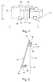
- FIG. 1 shows a simplified representation of a vehicle 20 in side view.
- a sliding door device 22 is installed with a sliding door 24.
- the vehicle has an X-axis (longitudinal axis), a Y-axis (transverse axis) and a Z-Z (vertical axis).
- the sliding door device 22 is used on the embodiment shown such that the sliding door 24 along the longitudinal axis X-X is displaceable, a displacement path 26 of the sliding door 24 thus extends along the longitudinal axis X-X of the vehicle.
- FIG. 1 shows a rear wheel 28 that laterally, ie along the transverse axis YY, in the displacement path 26 sliding door 24 protrudes.
- the sliding door 24 is swung during opening over the course of the displacement path 26 so that it protrudes with a lower closing edge 30 of a body outer wall 32 and thus is passed past the rear wheel 28 (see in particular also FIG. 2 ).
- FIG. 2 illustrates that the sliding door 24 is connected in the embodiment shown in the region of its upper closing edge 34 via first connecting means 36 with a first guide rail 38 and slidably mounted in its hanging and along the longitudinal axis XX. Via second connecting means 40, the sliding door is guided in a second guide rail 42.
- FIG. 2 shows that the second guide rail 42 in a horizontal plane, ie along the transverse axis YY offset in this area is arranged to the first guide rail 38 and the sliding door 24 at an angle to a vertical 44th stands.
- the vertical 44 is usually aligned perpendicular to the ground.
- the first guide rail 38 is formed as an upwardly open U-profile, in which a roller 46, which is connected to the first connecting means 36, runs.
- the U-profile and the roller 46 are matched to one another such that a pivoting of the sliding door 24 relative to the vertical 44 is possible.
- a relatively large pivot angle 50 is shown to illustrate the principle, it may be sufficient if the sliding door 24 in the open position starting from the first guide rail 38 an angle of only 0.5 ° to 3 °, preferably 1.6 ° with the vertical 44 includes.
- the angle range is to be understood only as an example, even angles of 0.5 ° to 10 °, preferably 3 to 5 °, depending on the application, may be useful.
- the second connecting means 40 is guided over a roller 46 in the second guide rail 42, wherein this is rotated in the illustrated embodiment by 90 ° to the upper roller 46.
- the connection of the second connecting means 40 with the second guide rail 42 can be realized in a variety of ways.
- the rollers 46 shown can also be arranged, for example, in the same plane, that is not rotated by 90 ° to each other.
- FIGS. 3 and 4 illustrate the invention by a simplified Schematic representation of the sliding door device 22 each in a horizontal section from above. It shows FIG. 3 the sliding door 24 in the closed position, FIG. 4 the sliding door 24 in the open position.
- the first guide rail 38 is shown by dashed lines for better understanding.
- the second guide rail 42 is arranged obliquely in the horizontal plane to the first guide rail 38.
- the sliding door 24 is connected to the second guide rail 42 via a plurality of, in the exemplary embodiment shown, three connecting means 40 arranged one behind the other in the longitudinal direction or along the longitudinal axis. Alternatively, only a single connection means 40 is sufficient.
- the difference in length of the second connecting means 40 is adapted to the oblique course of the second guide rail 42, that the lower closing edge 30 of the sliding door in the region of the displacement path 26 in each position parallel to the first guide rail.
- the foremost in the opening direction of the sliding door 24 second connecting means 40 has the smallest length, while the rearmost in the opening direction of the sliding door 24 second connecting means 40 has the greatest length.
- connection of the sliding door 24 with the first guide rail can be made via a plurality of first connecting means 36 in order to give the sliding door 24, for example, a higher stability.
- the vehicle sliding door device according to the invention is extremely simple and robust. There are no additional components needed to achieve instead of a purely linear displacement of the sliding door parallel to the body outer wall displacement with inclination. It is possible to easily integrate the vehicle sliding door device according to the invention in already manufactured vehicles, without having to make significant modifications. Especially when retrofitting vehicles with sliding door systems, there is often the problem that the wheel arch or the wheel project laterally beyond the dimensions of the vehicle, since the vehicles were not originally for the Use with such sliding doors were designed. Also, the invention makes it possible with simple means to produce different types of vehicles based on the same body, since no significant modifications must be made for the use of the vehicle sliding door device according to the invention, in contrast to another expansion of the same vehicle body.
Landscapes
- Engineering & Computer Science (AREA)
- Mechanical Engineering (AREA)
- Support Devices For Sliding Doors (AREA)
Applications Claiming Priority (1)
| Application Number | Priority Date | Filing Date | Title |
|---|---|---|---|
| DE102012101477.9A DE102012101477B4 (de) | 2012-02-23 | 2012-02-23 | Fahrzeugschiebetürvorrichtung mit schräger Führungsschiene |
Publications (2)
| Publication Number | Publication Date |
|---|---|
| EP2631100A2 true EP2631100A2 (fr) | 2013-08-28 |
| EP2631100A3 EP2631100A3 (fr) | 2016-01-06 |
Family
ID=47722123
Family Applications (1)
| Application Number | Title | Priority Date | Filing Date |
|---|---|---|---|
| EP13155611.0A Withdrawn EP2631100A3 (fr) | 2012-02-23 | 2013-02-18 | Dispositif de porte coulissante avec rail de guidage oblique |
Country Status (2)
| Country | Link |
|---|---|
| EP (1) | EP2631100A3 (fr) |
| DE (1) | DE102012101477B4 (fr) |
Cited By (2)
| Publication number | Priority date | Publication date | Assignee | Title |
|---|---|---|---|---|
| CN108533135A (zh) * | 2018-04-19 | 2018-09-14 | 深圳黑蚂蚁自动门有限公司 | 塞拉门 |
| CN111591116A (zh) * | 2019-02-20 | 2020-08-28 | 丰田自动车株式会社 | 车辆 |
Families Citing this family (2)
| Publication number | Priority date | Publication date | Assignee | Title |
|---|---|---|---|---|
| CN112196416B (zh) * | 2020-09-25 | 2022-06-17 | 中国直升机设计研究所 | 一种斜滑轨型滑动窗 |
| DE102023133598A1 (de) * | 2023-11-30 | 2025-06-05 | Rheinmetall Landsysteme Gmbh | Schiebetürmodul, turm und fahrzeug |
Citations (1)
| Publication number | Priority date | Publication date | Assignee | Title |
|---|---|---|---|---|
| DE102008058242A1 (de) | 2007-11-20 | 2009-07-09 | Acts Gmbh & Co. Kg | Schiebetüranordnung |
Family Cites Families (5)
| Publication number | Priority date | Publication date | Assignee | Title |
|---|---|---|---|---|
| DE1144602B (de) * | 1956-11-10 | 1963-02-28 | Daimler Benz Ag | Schiebetuer fuer Kraftfahrzeuge |
| US3982601A (en) * | 1975-05-01 | 1976-09-28 | Deere & Company | Guide support for slidable door of grader having an articulated frame |
| FR2420443A1 (fr) * | 1978-03-24 | 1979-10-19 | Bizien Jules | Perfectionnements apportes aux dispositifs de translation des portes coulissantes de vehicules notamment de camion |
| JP3407642B2 (ja) * | 1998-02-16 | 2003-05-19 | トヨタ車体株式会社 | 車両のスライドドア |
| FR2938586B1 (fr) * | 2008-11-18 | 2013-09-06 | Peugeot Citroen Automobiles Sa | Structure de porte coulissante pour vehicule, et vehicule equipe d'une telle structure |
-
2012
- 2012-02-23 DE DE102012101477.9A patent/DE102012101477B4/de not_active Expired - Fee Related
-
2013
- 2013-02-18 EP EP13155611.0A patent/EP2631100A3/fr not_active Withdrawn
Patent Citations (1)
| Publication number | Priority date | Publication date | Assignee | Title |
|---|---|---|---|---|
| DE102008058242A1 (de) | 2007-11-20 | 2009-07-09 | Acts Gmbh & Co. Kg | Schiebetüranordnung |
Cited By (3)
| Publication number | Priority date | Publication date | Assignee | Title |
|---|---|---|---|---|
| CN108533135A (zh) * | 2018-04-19 | 2018-09-14 | 深圳黑蚂蚁自动门有限公司 | 塞拉门 |
| CN111591116A (zh) * | 2019-02-20 | 2020-08-28 | 丰田自动车株式会社 | 车辆 |
| CN111591116B (zh) * | 2019-02-20 | 2023-08-29 | 丰田自动车株式会社 | 车辆 |
Also Published As
| Publication number | Publication date |
|---|---|
| DE102012101477B4 (de) | 2016-04-28 |
| DE102012101477A1 (de) | 2013-08-29 |
| EP2631100A3 (fr) | 2016-01-06 |
Similar Documents
| Publication | Publication Date | Title |
|---|---|---|
| DE102014206825B4 (de) | Scharniereinrichtung für eine KFZ- Tür | |
| EP3805513B1 (fr) | Porte roulante | |
| WO2013139618A1 (fr) | Ferrure pour un ouvrant de fenêtre ou de porte qui peut être déplacé par un mouvement parallèle et être déplacé en translation horizontalement dans cette position écartée en parallèle | |
| DE102012101477B4 (de) | Fahrzeugschiebetürvorrichtung mit schräger Führungsschiene | |
| WO2011076494A1 (fr) | Cabine d'ascenseur | |
| WO2009033566A1 (fr) | Unité de guidage pour plancher de chargement réglable en hauteur et véhicule à moteur équipé d'une telle unité de guidage et d'un plancher de chargement réglable en hauteur | |
| EP2759670B1 (fr) | Agencement de porte doté d'un système de verrouillage | |
| EP2860145B1 (fr) | Porte pliante dotée d'une glissière oblique | |
| EP3507161B1 (fr) | Dispositif permettant de rendre étanche au moins un vantail de porte d'un véhicule ferroviaire et véhicule ferroviaire | |
| EP3430219A1 (fr) | Dispositif de projection du battant d'une fenêtre ou d'une porte qui peut être amené au moins dans une position de rangement parallèle et qui est apte à coulisser horizontalement dans cette position | |
| DE2940169A1 (de) | Scharnier mit versenkt angeordneten teilen | |
| DE202018106885U1 (de) | Trittsystem für ein Fahrzeug | |
| DE2330900A1 (de) | Vorrichtung zum abstuetzen, sowie zum oeffnen und schliessen von fahrzeug-tueren | |
| EP3558731B1 (fr) | Porte arrière de carrosseries de poids lourds ou de remorques de poids lourds | |
| DE19834700B4 (de) | Vorrichtung zum Verschließen einer Wandöffnung | |
| DE19715712C2 (de) | Sektionaltor | |
| EP2746667A1 (fr) | Système pour ouvrir et fermer une porte de cheminée | |
| EP3984853A1 (fr) | Marche coulissante à entrainement passif | |
| DE102009056878A1 (de) | Tür für einen Kraftwagen | |
| EP2489552B1 (fr) | Véhicule automobile avec un rétroviseur | |
| EP4613960A1 (fr) | Bras pivotant à deux rouleaux | |
| EP3437952A1 (fr) | Joint d'étanchéité passif pour une porte coulissante | |
| DE102024136461A1 (de) | Zwei-Rollen-Schwenkarm | |
| EP3449078B1 (fr) | Groupe d'articles servant au montage de portes sectionnelles | |
| DE202023101132U1 (de) | Türsystem mit Verschlusselement innerhalb der Außenkontur des Fahrzeugs |
Legal Events
| Date | Code | Title | Description |
|---|---|---|---|
| PUAI | Public reference made under article 153(3) epc to a published international application that has entered the european phase |
Free format text: ORIGINAL CODE: 0009012 |
|
| AK | Designated contracting states |
Kind code of ref document: A2 Designated state(s): AL AT BE BG CH CY CZ DE DK EE ES FI FR GB GR HR HU IE IS IT LI LT LU LV MC MK MT NL NO PL PT RO RS SE SI SK SM TR |
|
| AX | Request for extension of the european patent |
Extension state: BA ME |
|
| PUAL | Search report despatched |
Free format text: ORIGINAL CODE: 0009013 |
|
| AK | Designated contracting states |
Kind code of ref document: A3 Designated state(s): AL AT BE BG CH CY CZ DE DK EE ES FI FR GB GR HR HU IE IS IT LI LT LU LV MC MK MT NL NO PL PT RO RS SE SI SK SM TR |
|
| AX | Request for extension of the european patent |
Extension state: BA ME |
|
| RIC1 | Information provided on ipc code assigned before grant |
Ipc: B60J 5/04 20060101ALN20151201BHEP Ipc: B60J 5/06 20060101AFI20151201BHEP |
|
| 17P | Request for examination filed |
Effective date: 20160706 |
|
| RBV | Designated contracting states (corrected) |
Designated state(s): AL AT BE BG CH CY CZ DE DK EE ES FI FR GB GR HR HU IE IS IT LI LT LU LV MC MK MT NL NO PL PT RO RS SE SI SK SM TR |
|
| STAA | Information on the status of an ep patent application or granted ep patent |
Free format text: STATUS: THE APPLICATION IS DEEMED TO BE WITHDRAWN |
|
| 18D | Application deemed to be withdrawn |
Effective date: 20180901 |