EP2631138B1 - Motorstart-steuervorrichtung, hybridfahrzeug und motorstartverfahren und programm - Google Patents
Motorstart-steuervorrichtung, hybridfahrzeug und motorstartverfahren und programm Download PDFInfo
- Publication number
- EP2631138B1 EP2631138B1 EP11834440.7A EP11834440A EP2631138B1 EP 2631138 B1 EP2631138 B1 EP 2631138B1 EP 11834440 A EP11834440 A EP 11834440A EP 2631138 B1 EP2631138 B1 EP 2631138B1
- Authority
- EP
- European Patent Office
- Prior art keywords
- engine
- rotational speed
- electric motor
- start control
- engine start
- Prior art date
- Legal status (The legal status is an assumption and is not a legal conclusion. Google has not performed a legal analysis and makes no representation as to the accuracy of the status listed.)
- Not-in-force
Links
Images






Classifications
-
- B—PERFORMING OPERATIONS; TRANSPORTING
- B60—VEHICLES IN GENERAL
- B60W—CONJOINT CONTROL OF VEHICLE SUB-UNITS OF DIFFERENT TYPE OR DIFFERENT FUNCTION; CONTROL SYSTEMS SPECIALLY ADAPTED FOR HYBRID VEHICLES; ROAD VEHICLE DRIVE CONTROL SYSTEMS FOR PURPOSES NOT RELATED TO THE CONTROL OF A PARTICULAR SUB-UNIT
- B60W20/00—Control systems specially adapted for hybrid vehicles
- B60W20/20—Control strategies involving selection of hybrid configuration, e.g. selection between series or parallel configuration
-
- B—PERFORMING OPERATIONS; TRANSPORTING
- B60—VEHICLES IN GENERAL
- B60K—ARRANGEMENT OR MOUNTING OF PROPULSION UNITS OR OF TRANSMISSIONS IN VEHICLES; ARRANGEMENT OR MOUNTING OF PLURAL DIVERSE PRIME-MOVERS IN VEHICLES; AUXILIARY DRIVES FOR VEHICLES; INSTRUMENTATION OR DASHBOARDS FOR VEHICLES; ARRANGEMENTS IN CONNECTION WITH COOLING, AIR INTAKE, GAS EXHAUST OR FUEL SUPPLY OF PROPULSION UNITS IN VEHICLES
- B60K6/00—Arrangement or mounting of plural diverse prime-movers for mutual or common propulsion, e.g. hybrid propulsion systems comprising electric motors and internal combustion engines
- B60K6/20—Arrangement or mounting of plural diverse prime-movers for mutual or common propulsion, e.g. hybrid propulsion systems comprising electric motors and internal combustion engines the prime-movers consisting of electric motors and internal combustion engines, e.g. HEVs
- B60K6/42—Arrangement or mounting of plural diverse prime-movers for mutual or common propulsion, e.g. hybrid propulsion systems comprising electric motors and internal combustion engines the prime-movers consisting of electric motors and internal combustion engines, e.g. HEVs characterised by the architecture of the hybrid electric vehicle
- B60K6/44—Series-parallel type
- B60K6/442—Series-parallel switching type
-
- B—PERFORMING OPERATIONS; TRANSPORTING
- B60—VEHICLES IN GENERAL
- B60K—ARRANGEMENT OR MOUNTING OF PROPULSION UNITS OR OF TRANSMISSIONS IN VEHICLES; ARRANGEMENT OR MOUNTING OF PLURAL DIVERSE PRIME-MOVERS IN VEHICLES; AUXILIARY DRIVES FOR VEHICLES; INSTRUMENTATION OR DASHBOARDS FOR VEHICLES; ARRANGEMENTS IN CONNECTION WITH COOLING, AIR INTAKE, GAS EXHAUST OR FUEL SUPPLY OF PROPULSION UNITS IN VEHICLES
- B60K6/00—Arrangement or mounting of plural diverse prime-movers for mutual or common propulsion, e.g. hybrid propulsion systems comprising electric motors and internal combustion engines
- B60K6/20—Arrangement or mounting of plural diverse prime-movers for mutual or common propulsion, e.g. hybrid propulsion systems comprising electric motors and internal combustion engines the prime-movers consisting of electric motors and internal combustion engines, e.g. HEVs
- B60K6/42—Arrangement or mounting of plural diverse prime-movers for mutual or common propulsion, e.g. hybrid propulsion systems comprising electric motors and internal combustion engines the prime-movers consisting of electric motors and internal combustion engines, e.g. HEVs characterised by the architecture of the hybrid electric vehicle
- B60K6/46—Series type
-
- B—PERFORMING OPERATIONS; TRANSPORTING
- B60—VEHICLES IN GENERAL
- B60K—ARRANGEMENT OR MOUNTING OF PROPULSION UNITS OR OF TRANSMISSIONS IN VEHICLES; ARRANGEMENT OR MOUNTING OF PLURAL DIVERSE PRIME-MOVERS IN VEHICLES; AUXILIARY DRIVES FOR VEHICLES; INSTRUMENTATION OR DASHBOARDS FOR VEHICLES; ARRANGEMENTS IN CONNECTION WITH COOLING, AIR INTAKE, GAS EXHAUST OR FUEL SUPPLY OF PROPULSION UNITS IN VEHICLES
- B60K6/00—Arrangement or mounting of plural diverse prime-movers for mutual or common propulsion, e.g. hybrid propulsion systems comprising electric motors and internal combustion engines
- B60K6/20—Arrangement or mounting of plural diverse prime-movers for mutual or common propulsion, e.g. hybrid propulsion systems comprising electric motors and internal combustion engines the prime-movers consisting of electric motors and internal combustion engines, e.g. HEVs
- B60K6/42—Arrangement or mounting of plural diverse prime-movers for mutual or common propulsion, e.g. hybrid propulsion systems comprising electric motors and internal combustion engines the prime-movers consisting of electric motors and internal combustion engines, e.g. HEVs characterised by the architecture of the hybrid electric vehicle
- B60K6/48—Parallel type
-
- B—PERFORMING OPERATIONS; TRANSPORTING
- B60—VEHICLES IN GENERAL
- B60W—CONJOINT CONTROL OF VEHICLE SUB-UNITS OF DIFFERENT TYPE OR DIFFERENT FUNCTION; CONTROL SYSTEMS SPECIALLY ADAPTED FOR HYBRID VEHICLES; ROAD VEHICLE DRIVE CONTROL SYSTEMS FOR PURPOSES NOT RELATED TO THE CONTROL OF A PARTICULAR SUB-UNIT
- B60W10/00—Conjoint control of vehicle sub-units of different type or different function
- B60W10/04—Conjoint control of vehicle sub-units of different type or different function including control of propulsion units
- B60W10/06—Conjoint control of vehicle sub-units of different type or different function including control of propulsion units including control of combustion engines
-
- B—PERFORMING OPERATIONS; TRANSPORTING
- B60—VEHICLES IN GENERAL
- B60W—CONJOINT CONTROL OF VEHICLE SUB-UNITS OF DIFFERENT TYPE OR DIFFERENT FUNCTION; CONTROL SYSTEMS SPECIALLY ADAPTED FOR HYBRID VEHICLES; ROAD VEHICLE DRIVE CONTROL SYSTEMS FOR PURPOSES NOT RELATED TO THE CONTROL OF A PARTICULAR SUB-UNIT
- B60W10/00—Conjoint control of vehicle sub-units of different type or different function
- B60W10/04—Conjoint control of vehicle sub-units of different type or different function including control of propulsion units
- B60W10/08—Conjoint control of vehicle sub-units of different type or different function including control of propulsion units including control of electric propulsion units, e.g. motors or generators
-
- B—PERFORMING OPERATIONS; TRANSPORTING
- B60—VEHICLES IN GENERAL
- B60W—CONJOINT CONTROL OF VEHICLE SUB-UNITS OF DIFFERENT TYPE OR DIFFERENT FUNCTION; CONTROL SYSTEMS SPECIALLY ADAPTED FOR HYBRID VEHICLES; ROAD VEHICLE DRIVE CONTROL SYSTEMS FOR PURPOSES NOT RELATED TO THE CONTROL OF A PARTICULAR SUB-UNIT
- B60W20/00—Control systems specially adapted for hybrid vehicles
-
- F—MECHANICAL ENGINEERING; LIGHTING; HEATING; WEAPONS; BLASTING
- F02—COMBUSTION ENGINES; HOT-GAS OR COMBUSTION-PRODUCT ENGINE PLANTS
- F02D—CONTROLLING COMBUSTION ENGINES
- F02D29/00—Controlling engines, such controlling being peculiar to the devices driven thereby, the devices being other than parts or accessories essential to engine operation, e.g. controlling of engines by signals external thereto
- F02D29/02—Controlling engines, such controlling being peculiar to the devices driven thereby, the devices being other than parts or accessories essential to engine operation, e.g. controlling of engines by signals external thereto peculiar to engines driving vehicles; peculiar to engines driving variable pitch propellers
-
- F—MECHANICAL ENGINEERING; LIGHTING; HEATING; WEAPONS; BLASTING
- F02—COMBUSTION ENGINES; HOT-GAS OR COMBUSTION-PRODUCT ENGINE PLANTS
- F02D—CONTROLLING COMBUSTION ENGINES
- F02D41/00—Electrical control of supply of combustible mixture or its constituents
- F02D41/02—Circuit arrangements for generating control signals
- F02D41/04—Introducing corrections for particular operating conditions
- F02D41/06—Introducing corrections for particular operating conditions for engine starting or warming up
- F02D41/062—Introducing corrections for particular operating conditions for engine starting or warming up for starting
-
- F—MECHANICAL ENGINEERING; LIGHTING; HEATING; WEAPONS; BLASTING
- F02—COMBUSTION ENGINES; HOT-GAS OR COMBUSTION-PRODUCT ENGINE PLANTS
- F02N—STARTING OF COMBUSTION ENGINES; STARTING AIDS FOR SUCH ENGINES, NOT OTHERWISE PROVIDED FOR
- F02N11/00—Starting of engines by means of electric motors
- F02N11/08—Circuits specially adapted for starting of engines
-
- F—MECHANICAL ENGINEERING; LIGHTING; HEATING; WEAPONS; BLASTING
- F02—COMBUSTION ENGINES; HOT-GAS OR COMBUSTION-PRODUCT ENGINE PLANTS
- F02N—STARTING OF COMBUSTION ENGINES; STARTING AIDS FOR SUCH ENGINES, NOT OTHERWISE PROVIDED FOR
- F02N11/00—Starting of engines by means of electric motors
- F02N11/08—Circuits specially adapted for starting of engines
- F02N11/0848—Circuits specially adapted for starting of engines with means for detecting successful engine start, e.g. to stop starter actuation
-
- B—PERFORMING OPERATIONS; TRANSPORTING
- B60—VEHICLES IN GENERAL
- B60K—ARRANGEMENT OR MOUNTING OF PROPULSION UNITS OR OF TRANSMISSIONS IN VEHICLES; ARRANGEMENT OR MOUNTING OF PLURAL DIVERSE PRIME-MOVERS IN VEHICLES; AUXILIARY DRIVES FOR VEHICLES; INSTRUMENTATION OR DASHBOARDS FOR VEHICLES; ARRANGEMENTS IN CONNECTION WITH COOLING, AIR INTAKE, GAS EXHAUST OR FUEL SUPPLY OF PROPULSION UNITS IN VEHICLES
- B60K6/00—Arrangement or mounting of plural diverse prime-movers for mutual or common propulsion, e.g. hybrid propulsion systems comprising electric motors and internal combustion engines
- B60K6/20—Arrangement or mounting of plural diverse prime-movers for mutual or common propulsion, e.g. hybrid propulsion systems comprising electric motors and internal combustion engines the prime-movers consisting of electric motors and internal combustion engines, e.g. HEVs
- B60K6/22—Arrangement or mounting of plural diverse prime-movers for mutual or common propulsion, e.g. hybrid propulsion systems comprising electric motors and internal combustion engines the prime-movers consisting of electric motors and internal combustion engines, e.g. HEVs characterised by apparatus, components or means specially adapted for HEVs
- B60K6/26—Arrangement or mounting of plural diverse prime-movers for mutual or common propulsion, e.g. hybrid propulsion systems comprising electric motors and internal combustion engines the prime-movers consisting of electric motors and internal combustion engines, e.g. HEVs characterised by apparatus, components or means specially adapted for HEVs characterised by the motors or the generators
- B60K2006/268—Electric drive motor starts the engine, i.e. used as starter motor
-
- B—PERFORMING OPERATIONS; TRANSPORTING
- B60—VEHICLES IN GENERAL
- B60K—ARRANGEMENT OR MOUNTING OF PROPULSION UNITS OR OF TRANSMISSIONS IN VEHICLES; ARRANGEMENT OR MOUNTING OF PLURAL DIVERSE PRIME-MOVERS IN VEHICLES; AUXILIARY DRIVES FOR VEHICLES; INSTRUMENTATION OR DASHBOARDS FOR VEHICLES; ARRANGEMENTS IN CONNECTION WITH COOLING, AIR INTAKE, GAS EXHAUST OR FUEL SUPPLY OF PROPULSION UNITS IN VEHICLES
- B60K6/00—Arrangement or mounting of plural diverse prime-movers for mutual or common propulsion, e.g. hybrid propulsion systems comprising electric motors and internal combustion engines
- B60K6/20—Arrangement or mounting of plural diverse prime-movers for mutual or common propulsion, e.g. hybrid propulsion systems comprising electric motors and internal combustion engines the prime-movers consisting of electric motors and internal combustion engines, e.g. HEVs
- B60K6/42—Arrangement or mounting of plural diverse prime-movers for mutual or common propulsion, e.g. hybrid propulsion systems comprising electric motors and internal combustion engines the prime-movers consisting of electric motors and internal combustion engines, e.g. HEVs characterised by the architecture of the hybrid electric vehicle
- B60K6/48—Parallel type
- B60K2006/4825—Electric machine connected or connectable to gearbox input shaft
-
- B—PERFORMING OPERATIONS; TRANSPORTING
- B60—VEHICLES IN GENERAL
- B60W—CONJOINT CONTROL OF VEHICLE SUB-UNITS OF DIFFERENT TYPE OR DIFFERENT FUNCTION; CONTROL SYSTEMS SPECIALLY ADAPTED FOR HYBRID VEHICLES; ROAD VEHICLE DRIVE CONTROL SYSTEMS FOR PURPOSES NOT RELATED TO THE CONTROL OF A PARTICULAR SUB-UNIT
- B60W20/00—Control systems specially adapted for hybrid vehicles
- B60W20/40—Controlling the engagement or disengagement of prime movers, e.g. for transition between prime movers
-
- B—PERFORMING OPERATIONS; TRANSPORTING
- B60—VEHICLES IN GENERAL
- B60W—CONJOINT CONTROL OF VEHICLE SUB-UNITS OF DIFFERENT TYPE OR DIFFERENT FUNCTION; CONTROL SYSTEMS SPECIALLY ADAPTED FOR HYBRID VEHICLES; ROAD VEHICLE DRIVE CONTROL SYSTEMS FOR PURPOSES NOT RELATED TO THE CONTROL OF A PARTICULAR SUB-UNIT
- B60W2510/00—Input parameters relating to a particular sub-units
- B60W2510/06—Combustion engines, Gas turbines
- B60W2510/0638—Engine speed
-
- B—PERFORMING OPERATIONS; TRANSPORTING
- B60—VEHICLES IN GENERAL
- B60W—CONJOINT CONTROL OF VEHICLE SUB-UNITS OF DIFFERENT TYPE OR DIFFERENT FUNCTION; CONTROL SYSTEMS SPECIALLY ADAPTED FOR HYBRID VEHICLES; ROAD VEHICLE DRIVE CONTROL SYSTEMS FOR PURPOSES NOT RELATED TO THE CONTROL OF A PARTICULAR SUB-UNIT
- B60W2510/00—Input parameters relating to a particular sub-units
- B60W2510/06—Combustion engines, Gas turbines
- B60W2510/0676—Engine temperature
-
- B—PERFORMING OPERATIONS; TRANSPORTING
- B60—VEHICLES IN GENERAL
- B60W—CONJOINT CONTROL OF VEHICLE SUB-UNITS OF DIFFERENT TYPE OR DIFFERENT FUNCTION; CONTROL SYSTEMS SPECIALLY ADAPTED FOR HYBRID VEHICLES; ROAD VEHICLE DRIVE CONTROL SYSTEMS FOR PURPOSES NOT RELATED TO THE CONTROL OF A PARTICULAR SUB-UNIT
- B60W2556/00—Input parameters relating to data
-
- B—PERFORMING OPERATIONS; TRANSPORTING
- B60—VEHICLES IN GENERAL
- B60W—CONJOINT CONTROL OF VEHICLE SUB-UNITS OF DIFFERENT TYPE OR DIFFERENT FUNCTION; CONTROL SYSTEMS SPECIALLY ADAPTED FOR HYBRID VEHICLES; ROAD VEHICLE DRIVE CONTROL SYSTEMS FOR PURPOSES NOT RELATED TO THE CONTROL OF A PARTICULAR SUB-UNIT
- B60W2710/00—Output or target parameters relating to a particular sub-units
- B60W2710/06—Combustion engines, Gas turbines
- B60W2710/0644—Engine speed
-
- B—PERFORMING OPERATIONS; TRANSPORTING
- B60—VEHICLES IN GENERAL
- B60W—CONJOINT CONTROL OF VEHICLE SUB-UNITS OF DIFFERENT TYPE OR DIFFERENT FUNCTION; CONTROL SYSTEMS SPECIALLY ADAPTED FOR HYBRID VEHICLES; ROAD VEHICLE DRIVE CONTROL SYSTEMS FOR PURPOSES NOT RELATED TO THE CONTROL OF A PARTICULAR SUB-UNIT
- B60W2710/00—Output or target parameters relating to a particular sub-units
- B60W2710/06—Combustion engines, Gas turbines
- B60W2710/0644—Engine speed
- B60W2710/065—Idle condition
-
- B—PERFORMING OPERATIONS; TRANSPORTING
- B60—VEHICLES IN GENERAL
- B60W—CONJOINT CONTROL OF VEHICLE SUB-UNITS OF DIFFERENT TYPE OR DIFFERENT FUNCTION; CONTROL SYSTEMS SPECIALLY ADAPTED FOR HYBRID VEHICLES; ROAD VEHICLE DRIVE CONTROL SYSTEMS FOR PURPOSES NOT RELATED TO THE CONTROL OF A PARTICULAR SUB-UNIT
- B60W30/00—Purposes of road vehicle drive control systems not related to the control of a particular sub-unit, e.g. of systems using conjoint control of vehicle sub-units
- B60W30/18—Propelling the vehicle
- B60W30/192—Mitigating problems related to power-up or power-down of the driveline, e.g. start-up of a cold engine
-
- F—MECHANICAL ENGINEERING; LIGHTING; HEATING; WEAPONS; BLASTING
- F02—COMBUSTION ENGINES; HOT-GAS OR COMBUSTION-PRODUCT ENGINE PLANTS
- F02N—STARTING OF COMBUSTION ENGINES; STARTING AIDS FOR SUCH ENGINES, NOT OTHERWISE PROVIDED FOR
- F02N2200/00—Parameters used for control of starting apparatus
- F02N2200/02—Parameters used for control of starting apparatus said parameters being related to the engine
- F02N2200/022—Engine speed
-
- F—MECHANICAL ENGINEERING; LIGHTING; HEATING; WEAPONS; BLASTING
- F02—COMBUSTION ENGINES; HOT-GAS OR COMBUSTION-PRODUCT ENGINE PLANTS
- F02N—STARTING OF COMBUSTION ENGINES; STARTING AIDS FOR SUCH ENGINES, NOT OTHERWISE PROVIDED FOR
- F02N2300/00—Control related aspects of engine starting
- F02N2300/10—Control related aspects of engine starting characterised by the control output, i.e. means or parameters used as a control output or target
- F02N2300/102—Control of the starter motor speed; Control of the engine speed during cranking
-
- Y—GENERAL TAGGING OF NEW TECHNOLOGICAL DEVELOPMENTS; GENERAL TAGGING OF CROSS-SECTIONAL TECHNOLOGIES SPANNING OVER SEVERAL SECTIONS OF THE IPC; TECHNICAL SUBJECTS COVERED BY FORMER USPC CROSS-REFERENCE ART COLLECTIONS [XRACs] AND DIGESTS
- Y02—TECHNOLOGIES OR APPLICATIONS FOR MITIGATION OR ADAPTATION AGAINST CLIMATE CHANGE
- Y02T—CLIMATE CHANGE MITIGATION TECHNOLOGIES RELATED TO TRANSPORTATION
- Y02T10/00—Road transport of goods or passengers
- Y02T10/60—Other road transportation technologies with climate change mitigation effect
- Y02T10/62—Hybrid vehicles
-
- Y—GENERAL TAGGING OF NEW TECHNOLOGICAL DEVELOPMENTS; GENERAL TAGGING OF CROSS-SECTIONAL TECHNOLOGIES SPANNING OVER SEVERAL SECTIONS OF THE IPC; TECHNICAL SUBJECTS COVERED BY FORMER USPC CROSS-REFERENCE ART COLLECTIONS [XRACs] AND DIGESTS
- Y02—TECHNOLOGIES OR APPLICATIONS FOR MITIGATION OR ADAPTATION AGAINST CLIMATE CHANGE
- Y02T—CLIMATE CHANGE MITIGATION TECHNOLOGIES RELATED TO TRANSPORTATION
- Y02T10/00—Road transport of goods or passengers
- Y02T10/60—Other road transportation technologies with climate change mitigation effect
- Y02T10/72—Electric energy management in electromobility
-
- Y—GENERAL TAGGING OF NEW TECHNOLOGICAL DEVELOPMENTS; GENERAL TAGGING OF CROSS-SECTIONAL TECHNOLOGIES SPANNING OVER SEVERAL SECTIONS OF THE IPC; TECHNICAL SUBJECTS COVERED BY FORMER USPC CROSS-REFERENCE ART COLLECTIONS [XRACs] AND DIGESTS
- Y10—TECHNICAL SUBJECTS COVERED BY FORMER USPC
- Y10S—TECHNICAL SUBJECTS COVERED BY FORMER USPC CROSS-REFERENCE ART COLLECTIONS [XRACs] AND DIGESTS
- Y10S903/00—Hybrid electric vehicles, HEVS
- Y10S903/902—Prime movers comprising electrical and internal combustion motors
- Y10S903/903—Prime movers comprising electrical and internal combustion motors having energy storing means, e.g. battery, capacitor
- Y10S903/93—Conjoint control of different elements
Definitions
- the present invention relates to an engine start control device, a hybrid vehicle and an engine start method, and a computer program.
- the electric motor can start the engine (for example, see Patent Literature PTL1).
- US 2002/0179 348 A discloses an engine start procedure using temperature dependent threshold speeds. Engine start is deemed successful if engine speed exceeds an upper flare speed threshold for a given time and remains above a lower flare speed threshold, also for a given time.
- an objective of the present invention is to provide an engine start control device, a hybrid vehicle and an engine start method, and a computer program that are capable of reducing the electric power consumption when the electric motor starts the engine, and reducing the time required to start the engine.
- An aspect of the present invention is an engine start control device.
- the engine start control device of the present invention is an engine start control device of a hybrid vehicle that includes an engine and an electric motor, that is capable of running by the engine or the electric motor or capable of running by a cooperation between the engine and the electric motor, and that starts the engine by the electric motor, wherein a series of controls is repeatedly performed and the series of controls includes increasing a rotational speed of the engine to a first rotational speed by the electric motor, supplying fuel to the engine of which rotational speed has been increased to the first rotational speed, detecting a further increase in the rotational speed of the engine, temporarily stopping a supply of electric power to the electric motor when the further increase in the rotational speed of the engine is not detected, and interrupting the supply of fuel to the engine and resuming the supply of electric power to the electric motor when the rotational speed of the engine decreases to a second rotational speed, and the series of controls is terminated as it is determined that the start of the engine has been completed when the further increase in the rotational
- the engine start control device of the present invention can control the first rotational speed and the second rotational speed to change according to temperature information on the engine.
- the engine start control device of the present invention can control the rotational speed and/or a torque of the electric motor when the engine is started to be set variable according to the temperature information on the engine.
- the temperature information on the engine is a cooling water temperature of the engine.
- the hybrid vehicle of the present invention includes the engine start control device of the present invention.
- the engine start control method of the present invention is an engine start control method of a hybrid vehicle that includes an engine and an electric motor, that is capable of running by the engine or the electric motor or capable of running by a cooperation between the engine and the electric motor, and that starts the engine by the electric motor, including a first step for increasing a rotational speed of the engine to a first rotational speed by the electric motor, a second step for supplying fuel to the engine of which rotational speed has been increased to the first rotational speed by a process of the first step, and detecting a further increase in the rotational speed of the engine, a third step for temporarily stopping a supply of electric power to the electric motor when the further increase in the rotational speed of the engine is not detected by a process of the second step, a fourth step for interrupting the supply of fuel to the engine and resuming the supply of electric power to the electric motor when the rotational speed of the engine decreases to a second rotational speed by a process of the third step, and
- the computer program of the present invention is a computer program for causing an information processing unit to implement a function of the engine start control device of the present invention.
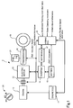
- Fig. 1 is a block diagram for illustrating an exemplary structure of a hybrid vehicle 1.
- the hybrid vehicle 1 is an example of a vehicle.
- the hybrid vehicle 1 is driven by an engine (internal combustion engine) 10 and/or an electric motor 13 through a transmission that is a semiautomatic transmission.
- the electric motor 13 can start the engine 10.
- the semiautomatic transmission is a transmission that can automatically shift the gears while having the same structure as a manual transmission.
- the hybrid vehicle 1 includes the engine 10, an engine Electronic Control Unit (ECU) 11, a clutch 12, the electric motor 13, an inverter 14, a battery 15, a transmission 16, a motor ECU 17, a hybrid ECU 18, a wheel 19, a key switch 20, and a shift unit 21.
- the transmission 16 includes the above-mentioned semiautomatic transmission, and is operated by the shift unit 21 including a drive range (hereinafter, referred to as a D (Drive) range).
- the engine 10 is an example of an internal combustion engine, and is controlled by the engine ECU 11.
- the engine 10 internally combusts gasoline, light oil, Compressed Natural Gas (CNG), Liquefied Petroleum Gas (LPG), alternative fuel, or the like in order to generate power for rotating a shaft and transmit the generated power to the clutch 12.
- CNG Compressed Natural Gas
- LPG Liquefied Petroleum Gas
- the engine ECU 11 is a computer working in coordination with the motor ECU 17 according to the instructions from the hybrid ECU 18, and controls the engine 10, for example, the amount of fuel injection and the valve timing.
- the engine ECU 11 includes a Central Processing Unit (CPU), an Application Specific Integrated Circuit (ASIC), a microprocessor, a Digital Signal Processor (DSP), and the like, and internally has an operation unit, a memory, an Input/Output (I/O) port, and the like.
- CPU Central Processing Unit
- ASIC Application Specific Integrated Circuit
- DSP Digital Signal Processor
- the clutch 12 is controlled by the hybrid ECU 18, and transmits the shaft output from the engine 10 to the wheel 19 through the electric motor 13 and the transmission 16.
- the clutch 12 mechanically connects the rotating shaft of the engine 10 to the rotating shaft of the electric motor 13 by the control of the hybrid ECU 18 in order to transmit the shaft output of the engine 10 to the electric motor 13.
- the clutch 12 cuts the mechanical connection between the rotating shaft of the engine 10 and the rotating shaft of the electric motor 13 so that the shaft of the engine 10 and the rotating shaft of the electric motor 13 can rotate at different rotational speeds from each other.
- the clutch 12 mechanically connects the rotating shaft of the engine 10 to the rotating shaft of the electric motor 13, for example, when the hybrid vehicle 1 runs by the power of the engine 10 and this causes the electric motor 13 to generate electric power, when the driving force of the electric motor 13 assists the engine 10, and when the electric motor 13 starts the engine 10.
- the clutch 12 cuts the mechanical connection between the rotating shaft of the engine 10 and the rotating shaft of the electric motor 13 when the engine 10 stops or is in an idling state and the hybrid vehicle 1 runs by the driving force of the electric motor 13, and when the hybrid vehicle 1 reduces the speed or runs on the down grade and the electric motor 13 generates electric power (regenerates electric power) while the engine 10 stops or is in an idling state.
- the clutch 12 differs from the clutch operated by the driver's operation of a clutch pedal, and is operated by the control of the hybrid ECU 18.
- the electric motor 13 is a so-called motor generator that supplies a shaft output to the transmission 16 by generating the power for rotating the shaft using the electric power supplied from the inverter 14, or that supplies electric power to the inverter 14 by generating the electric power using the power for rotating the shaft supplied from the transmission 16.
- the electric motor 13 when the hybrid vehicle 1 gains the speed or runs at a constant speed, the electric motor 13 generates the power for rotating the shaft to supply the shaft output to the transmission 16 in order to cause the hybrid vehicle 1 to run in cooperation with the engine 10.
- the electric motor 13 works as an electric generator, for example, when the electric motor 13 is driven by the engine 10, or when the hybrid vehicle 1 runs without power, for example, the hybrid vehicle 1 reduces the speed or runs on the down grade. In that case, electric power is generated by the power for rotating the shaft supplied from the transmission 16 and is supplied to the inverter 14 in order to charge the battery 15.
- the inverter 14 is controlled by the motor ECU 17, and converts the direct voltage from the battery 15 into an alternating voltage or converts the alternating voltage from the electric motor 13 into a direct voltage.
- the inverter 14 converts the direct voltage from the battery 15 into an alternating voltage and supplies the electric power to the electric motor 13.
- the inverter 14 converts the alternating voltage from the electric motor 13 into a direct voltage.
- the inverter 14 works as a rectifier and a voltage regulator for supplying a direct voltage to the battery 15.
- the battery 15 is a secondary cell capable of being charged and discharged.
- the battery 15 supplies electric power to the electric motor 13 through the inverter 14 when the electric motor 13 generates power.
- the battery 15 is charged with the electric power generated by the electric motor 13 when the electric motor 13 generates electric power.
- the transmission 16 includes a semiautomatic transmission (not shown in the drawings) that selects one of a plurality of gear ratios (change gear ratios) according to a shift instruction signal from the hybrid ECU 18 in order to shift the change gear ratios and transmit the gear-shifted power of the engine 10 and/or of the electric motor 13 to the wheel 19.
- the transmission 16 transmits the power from the wheel 19 to the electric motor 13, for example, when the vehicle reduces the speed or runs on the down grade.
- the semiautomatic transmission can also shift the gear position to a given gear number by the driver's hand operation of the shift unit 21.
- the motor ECU 17 is a computer working in coordination with the engine ECU 11 according to the instructions from the hybrid ECU 18, and controls the electric motor 13 by controlling the inverter 14.
- the motor ECU 17 includes a CPU, an ASIC, a microprocessor, a DSP, and the like, and internally has an operation unit, a memory, an I/O port, and the like.
- the hybrid ECU 18 is an example of a computer.
- the hybrid ECU 18 obtains accelerator opening information, brake operation information, vehicle speed information, the gear position information obtained from the transmission 16, and the engine rotational speed information obtained from the engine ECU 11 in order to refer to the information, control the clutch 12 and supply the shift instruction in order to control the transmission 16.
- the hybrid ECU 18 further gives the control instructions of the electric motor 13 and the inverter 14 to the motor ECU 17 based on the obtained State of Charge (SOC) information on the battery 15 and other information, and gives the control instruction of the engine 10 to the engine ECU 11.
- the hybrid ECU 18 includes a CPU, an ASIC, a microprocessor, a DSP, and the like, and internally has an operation unit, a memory, an I/O port, and the like.
- a computer program to be executed by the hybrid ECU 18 can be installed on the hybrid ECU 18 that is a computer in advance by being stored in a non-volatile memory inside the hybrid ECU 18 in advance.
- the engine ECU 11, the motor ECU 17, and the hybrid ECU 18 are connected to each other, for example, through a bus complying with the standard of the Control Area Network (CAN) or the like.
- CAN Control Area Network
- the wheel 19 is a drive wheel for transmitting the driving force to the road surface. Note that, although only a wheel 19 is illustrated in Fig. 1 , the hybrid vehicle 1 actually includes a plurality of the wheels 19.
- the key switch 20 is a switch that is turned ON/OFF, for example, by insertion of a key by the user at the start of drive. Turning ON the switch activates each unit of the hybrid vehicle 1, and turning OFF the key switch 20 stops each unit of the hybrid vehicle 1.
- Fig. 2 is a block diagram for illustrating an exemplary configuration of a function implemented in the hybrid ECU 18 that executes a computer program.
- an engine start control unit 30 is implemented.
- the engine start control unit 30 inputs the engine rotational speed information from the engine ECU 11, and outputs an electric motor control instruction to the motor ECU 17.
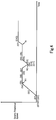
- the engine start control process performed in the hybrid ECU 18 executing a computer program will be described. Note that, as situations in which the engine start process is performed, there are a case where the engine 10 is started when the key switch 20 is turned ON at the start of drive of the hybrid vehicle 1, and a case where the engine 10 is started when a condition for stopping idling is removed while the hybrid vehicle 1 is temporarily stopped by an idling stop function (not shown in the drawings) after the hybrid vehicle 1 has already run.
- step S1 the hybrid ECU 18 has executed a computer program and the engine start control unit 30 is implemented by the hybrid ECU 18. Then, the process goes to step S1.
- step S1 when the key switch 20 is turned ON at the start of drive of the hybrid vehicle 1, or when the condition for stopping idling is removed while the hybrid vehicle 1 stops idling after the hybrid vehicle 1 has already run, the engine start control unit 30 recognizes them. Then, the process goes to step S2.
- step S2 the engine start control unit 30 engages the clutch 12, and then the process goes to step S3.
- step S3 the engine start control unit 30 instructs the motor ECU 17 to start the electric motor 13, and then the process goes to step S4.
- step S4 the engine start control unit 30 determines whether the rotational speed of the engine 10 increases to a predetermined rotational speed R1 after the engine 10 that is connected to the electric motor 13 through the clutch 12 is rotated by the torque of the electric motor 13.
- step S4 the rotational speed of the engine 10 has increased to the rotational speed R1
- the process goes to step S5.
- the torque of the electric motor 13 when the engine 10 is started is fixed at a predetermined value. It is preferable to set the predetermined value relatively high on the assumption of a situation where it is most difficult to start the engine 10, for example, in winter.
- step S5 the engine start control unit 30 instructs the motor ECU 17 to keep the rotational speed of the electric motor 13 at a constant speed around the rotational speed R1, and then the process goes to step S6.
- step S6 the engine start control unit 30 instructs the engine ECU 11 to supply fuel to the engine 10, and then the process goes to step S7.
- step S7 the engine start control unit 30 determines whether the rotational speed of the engine 10 that is connected to the electric motor 13 through the clutch 12 becomes equal to or less than the rotational speed R1.
- step S7 the rotational speed of the engine 10 has been equal to or less than the rotational speed R1
- step S8 the process goes to step S8.
- step S7 it is determined that the rotational speed of the engine 10 has exceeded the rotational speed R1
- step S8 the engine start control unit 30 stops the electric power supplied to the electric motor 13, and then the process goes to step S9.
- step S9 the engine start control unit 30 determines whether the rotational speed of the engine 10 that is connected to the electric motor 13 through the clutch 12 has decreased to a predetermined rotational speed R2 ( ⁇ R1).
- a predetermined rotational speed R2 ⁇ R1
- the process goes to step S10.
- the rotational speed R2 is lower than the rotational speed R1.
- the proportion of the rotational speed R2 to the rotational speed R1 has been predetermined. In other words, when the value of the rotational speed R1 is determined, in response, the value of the rotational speed R2 is also determined.
- step S10 the engine start control unit 30 instructs the engine ECU 11 to interrupt supplying fuel to the engine 10, and then the process goes to step S11.
- step S11 the engine start control unit 30 resumes supplying electric power to the electric motor 13, and then the process goes back to step S3.
- step S3 As the electric motor 13 is started, the rotational speed of the engine 10 starts to increase.
- step S4 the rotational speed of the engine 10 further continues to increase and reaches the rotational speed R1.
- step S5 the rotational speed of the electric motor 13 becomes a constant speed around the rotational speed R1. After that, the rotational speed of the engine 10 also becomes the constant speed.
- step S6 fuel is supplied to the engine 10.
- step S7 it is determined whether the rotational speed of the engine 10 is equal to or less than the rotational speed R1.
- step S8 the electric power supplied to the electric motor 13 is stopped. As this causes the rotational speed of the electric motor 13 to start to decrease, the rotational speed of the engine 10 also starts to decrease.
- step S9 the rotational speed of the engine 10 decreases to the rotational speed R2.
- step S10 when the rotational speed of the engine 10 decreases to the rotational speed R2, the supply of fuel to the engine 10 is interrupted.
- step S11 the supply of electric power to the electric motor 13 is resumed, and then the process goes back to step S3.
- step S4 the rotational speed of the engine 10 starts to increase.
- step S5 the rotational speed of the electric motor 13 becomes a constant speed around the rotational speed R1.
- step S6 fuel is supplied to the engine 10.
- step S7 it is determined whether the rotational speed of the engine 10 is equal to or less than the rotational speed R1. In the example, because the start of the engine 10 has succeeded, the rotational speed of the engine 10 exceeds the rotational speed R1. This completes the start of the engine 10 (END).
- the electric motor 13 increases the rotational speed of the engine 10 to the rotational speed R1, fuel is supplied to the engine 10 of which rotational speed has been increased to the rotational speed R1, and a further increase in the rotational speed of the engine 10 is detected.
- the supply of electric power to the electric motor 13 is temporarily stopped.
- the rotational speed of the engine 10 has decreased to the rotational speed R2
- the supply of fuel to the engine 10 is interrupted and the supply of electric power to the electric motor 13 is resumed.
- the further increase in the rotational speed of the engine 10 is detected, or when the rotational speed of the engine 10 has not decreased to the rotational speed R2, it is determined that the start of the engine 10 has been completed.
- detecting the variation of the rotational speed of the engine 10 confirms the start of the engine 10. Further, when the start of the engine 10 has been unsuccessful, the process for restarting the engine 10 is performed without decreasing the rotational speed of the engine 10 to zero. This can reduce the electric power consumption when the electric motor 13 starts the engine 10 and also reduce the time required to start the engine 10.
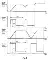
- a rotational speed r of the electric motor 13 for starting the engine 10 in the prior art method is larger in comparison with the embodiment of the present invention (r > R1).
- the time required to start the engine 10 in the prior art method is longer in comparison with the embodiment of the present invention (t > T).
- the engine start method according to the embodiment of the present invention can reduce the electric power consumption when the electric motor 13 starts the engine 10 and also reduce the time required to start the engine 10 in comparison with the past method.
- the rotational speed of the electric motor in the engine start method according to an embodiment of the present invention is illustrated together with the time course.
- the electric motor torque in the engine start method according to an embodiment of the present invention is illustrated together with the time course.
- the rotational speed of the electric motor in the prior art engine start method is illustrated together with the time course.
- the electric motor torque in the prior art engine start method is illustrated together with the time course.
- a torque tr of the electric motor 13 for starting the engine 10 in the prior art method is larger in comparison with the embodiment of the present invention (tr > TR).
- a time t10 required to start the engine 10 in the prior art method is longer in comparison with the embodiment of the present invention (t10 > T10).
- the engine start method according to the embodiment of the present invention can reduce the electric power consumption when the electric motor 13 starts the engine 10 and also reduce the time required to start the engine 10 in comparison with the past method.
- the rotational speed of the electric motor in the engine start method according to an embodiment of the present invention is illustrated together with the time course.
- the electric motor output in the engine start method according to an embodiment of the present invention is illustrated together with the time course.
- the rotational speed of the electric motor in the prior art engine start method is illustrated together with the time course.
- the electric motor output in the prior art engine start method is illustrated together with the time course.
- an output p of the electric motor 13 for starting the engine 10 in the prior art method is larger in comparison with the embodiment of the present invention (p > P).
- the time t10 required to start the engine 10 in the prior art method is longer in comparison with the embodiment of the present invention (t10 > T10).
- the engine start method according to the embodiment of the present invention can reduce the electric power consumption when the electric motor 13 starts the engine 10 and also reduce the time required to start the engine 10 in comparison with the past method.
- rotational speeds R1 and R2 and a torque of an electric motor 13 that are used for the start control of an engine 10 and that are fixedly set at the engine start control unit 30 in the hybrid vehicle 1 are variable based on the cooling water temperature information of a radiator 22.
- the rotational speed R2 is lower than the rotational speed R1, and the proportion of the rotational speed R2 to the rotational speed R1 has been predetermined.
- determining the value of the rotational speed R1 automatically determines the value of the rotational speed R2.
- the values of the rotational speeds R1 and R2 have been described as fixed values in the first embodiment, the values of the rotational speeds R1 and R2 are set as variable values in the second embodiment.
- the values of the rotational speeds R1 and R2 are variable according to the cooling water temperature of the radiator 22. In that case, the rotational speeds R1 and R2 are set lower because it is easy to start the engine 10 when the cooling water temperature is shown as a relatively high temperature. In the contrary, the rotational speeds R1 and R2 are set higher because it is difficult to start the engine 10 when the cooling water temperature is shown as a relatively low temperature.
- the torque of the electric motor 13 when the engine 10 is started is also set lower because it is easy to start the engine 10 when the cooling water temperature is shown as a relatively high temperature. In the contrary, the torque is set higher because it is difficult to start the engine 10 when the cooling water temperature is shown as a relatively low temperature.
- Fig. 8 is a block diagram for illustrating an exemplary structure of the hybrid vehicle 1A.
- the structure of the hybrid vehicle 1A partially differs from the structure of the hybrid vehicle 1.
- a hybrid ECU 18A can receive the cooling water temperature information of the radiator 22 through an engine ECU 11A. Further, the hybrid ECU 18A performs a control based on the operation information of the key switch 20. Because the other components in the hybrid vehicle 1A are the same as those of the hybrid vehicle 1, the descriptions are omitted.
- Fig. 9 is a block diagram for illustrating an exemplary configuration of a function implemented in a hybrid ECU 18A executing a computer program.
- a function of an engine start control unit 30A (referred to as an engine start control device in the appended claims) is implemented.
- the engine start control unit 30A instructs the engine ECU 11, a clutch 12, and an electric motor ECU 17 to control the engine start based on key switch operation information and the cooling water temperature information in addition to the engine rotational speed information.
- the target starting rotational speed denotes a target rotational speed of the electric motor 13 when the electric motor 13 starts the engine 10.
- the target starting rotational speed corresponds to the rotational speed R1 in the first embodiment.
- the target starting torque denotes a target torque of the electric motor 13 when the electric motor 13 starts the engine 10. While the torque of the electric motor 13 is constant in the first embodiment, the torque is set at the target starting torque in the second embodiment.
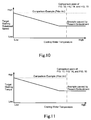
- Fig. 10 the cooling water temperature is shown on the horizontal axis, and the target starting rotational speed is shown on the vertical axis.
- Fig. 11 the cooling water temperature is shown on the horizontal axis, and the target starting torque is shown on the vertical axis.
- the target starting rotational speed is set high when the cooling water temperature is low
- the target starting rotational speed is set low when the cooling water temperature is high.
- the target starting torque is set high when the cooling water temperature is low
- the target starting torque is set low when the cooling water temperature is high.
- the comparison examples are shown as dashed lines in Figs. 10 and 11 .
- the target starting rotational speed and the target starting torque are set at high values, respectively, on the assumption of the case where it is most difficult to start the engine 10 (the cooling water temperature is lowest).
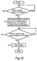
- step S20 to step S23 in Fig. 12 is a cycle of the process, and is repeatedly performed as long as a key switch 20 is the ON state.
- the key switch 20 is the ON state
- the hybrid ECU 18A has executed a computer program
- a function of the engine start control unit 30A is implemented by the hybrid ECU 18A. Then, the process goes to step S20.
- step S20 the engine start control unit 30A determines whether the cooling water temperature information transmitted from the radiator 22 through the engine ECU 11A has been detected. When it is determined in step S20 that the cooling water temperature information has been detected, the process goes to step S21. On the other hand, when it is determined in step S20 that the cooling water temperature has not been detected, step S20 in the process is repeated.
- step S21 the engine start control unit 30A sets a target starting rotational speed (namely, the rotational speed R1) and a target starting torque that correspond to the cooling water temperature detected in step S20, and then the process goes to step S22.
- a target starting rotational speed namely, the rotational speed R1
- a target starting torque that correspond to the cooling water temperature detected in step S20
- step S22 the engine start control unit 30A determines whether the key switch 20 has been set at the position for starting the engine 10. When it is determined in step S22 that the key switch 20 has been set at the position for starting the engine 10, the process goes to step S23. On the other hand, when it is determined in step S22 that the key switch 20 has not been set at the position for starting the engine 10, step S22 in the process is repeated.
- step S23 the engine start control unit 30A causes the electric motor 13 to start the engine 10, and the process is completed (END).
- Figs. 13, 14, and 15 show the states in that the start of the engine 10 has succeeded in the shortest time after the "No" in step S7 of the flowchart illustrated in Fig. 3 at the first embodiment.
- Fig. 13 the time course is shown on the horizontal axis, and the rotational speed of the electric motor 13 is shown on the vertical axis.
- the solid line of Fig. 13 shows the rotational speed of the electric motor 13 at the start of the engine 10 by the control of the engine start control unit 30A.
- the dashed line shows the rotational speed of the electric motor 13 at the start of the engine 10 in prior art as a comparison example.
- Figs. 13, 14, and 15 illustrate the comparisons between the comparison examples (prior art) and the examples of the embodiment of the present invention at the positions that are in the region where the cooling water temperature is high and that are indicated by alternate long and short dashed lines in Figs. 10 and 11 .
- Fig. 14 the time course is shown on the horizontal axis, and the torque of the electric motor 13 is shown on the vertical axis.
- the solid line in Fig. 14 denotes the torque of the electric motor 13 at the start of the engine 10 by the control of the engine start control unit 30A, and the dashed line denotes the torque of the electric motor 13 at the start of the engine 10 in prior art as a comparison example. From this, it is found that the torque in prior art is larger at the start in comparison with the example of the embodiment of the present invention as shown in Fig. 14 because the target starting rotational speed and the target starting torque are set lower than those of the case in prior art at the examples in Figs. 10 and 11 .
- Fig. 15 the time course is shown on the horizontal axis, and the output of the electric motor 13 is shown on the vertical axis.
- the solid line in Fig. 15 denotes the output of the electric motor 13 at the start of the engine 10 by the control of the engine start control unit 30A, and the dashed line denotes the output of the electric motor 13 at the start of the engine 10 in prior art as a comparison example. From this, it is found that the output in prior art is larger at the start in comparison with the example of the embodiment of the present invention as shown in Fig. 15 because the target starting rotational speed and the target starting torque are set lower than those of the case in prior art at the examples in Figs. 10 and 11 .
- the target starting rotational speed (namely, the rotational speed R1) and target starting torque of the electric motor 13 when the engine 10 is started are set variable according to the cooling water temperature of the engine 10 so that the electric power consumption required to start the engine 10 can be reduced.
- the engine start control unit 30A detects the cooling water temperature of the radiator 22 in order to perform a start control because it is most advantageous to use a cooling water temperature indicator of the radiator 22 since a vehicle in prior art necessarily has the cooling water temperature indicator.
- the hybrid vehicle 1A has any other means to obtain temperature information, for example, on the temperature of the chassis of the engine 10, the temperature of the engine room, or the temperature of the engine oil, the engine start control unit 30A can perform a start control using one of the temperature information.
- the engine start control unit 30A can perform a start control by properly setting the target starting rotational speed and the target starting torque according to season information and time information, for example, indicating whether it is a cold night or a warm day without depending on the direct temperature information since the clock function indicates the season (spring, summer, autumn, and winter).
- season information and time information for example, indicating whether it is a cold night or a warm day without depending on the direct temperature information since the clock function indicates the season (spring, summer, autumn, and winter).
- the driver can input the season information, the time information or the like by hand.
- the engine start control unit 30A sets both of the target starting rotational speed and target starting torque of the electric motor 13 according to the cooling water temperature of the radiator 22
- the engine start control unit 30A can set one of the target starting rotational speed and target starting torque of the electric motor 13 according to the cooling water temperature of the radiator 22.
- prior experiments in which various temperature conditions are set can confirm how much torque is required to rotate the shaft of the engine 10 at each of the temperature conditions in order to reach the rotational speed capable of starting the engine 10. Based on the results from such experiments, only the target starting torque of the electric motor 13 can be set according to the cooling water temperature of the radiator 22 in advance. Alternatively, it is not necessary to set the target starting torque in advance if the torque of the electric motor 13 is controlled to gradually be increased until the rotational speed reaches the target starting rotational speed during the actual start in order to control to finally reach the target starting rotational speed while only the target starting rotational speed of the electric motor 13 is set according to the cooling water temperature of the radiator 22 in advance.
- the computer program executed by the hybrid ECUs 18 and 18A is installed on the hybrid ECUs 18 and 18A in advance in the description above, the computer program can be installed on the hybrid ECUs 18 and 18A as a computer by attaching removable media recording the computer program (storing the computer program), for example, to a drive (not shown in the drawings) and storing the computer program read from the removable media in a non-volatile storing the computer program read from the removable media in a non-volatile memory inside the hybrid ECUs 18 and 18A, or receiving, by a communication unit (not shown in the drawings), a computer program transmitted through a wired or wireless transmission medium and storing the computer program in a non-volatile memory inside the hybrid ECUs 18 and 18A.
- each ECU can be implemented by an ECU combining each of the ECUs.
- an ECU can newly be provided by the subdivision of the function of each ECU.
- the computer program executed by the computer can be for performing the process in chronological order according to the order described herein or can be for performing the process in parallel or at the necessary timing, for example, when the computer program is invoked.
- the boundaries of the region for determination can variously be changed, for example, the "equal to or more than” can be changed into “exceeds” and the “less than” can be changed into “equal to or less than” in the description of the above-mentioned flowchart.
- the engine 10 has been described as an internal combustion engine, the engine 10 can also be a heat engine including an external combustion engine.
Landscapes
- Engineering & Computer Science (AREA)
- Chemical & Material Sciences (AREA)
- Combustion & Propulsion (AREA)
- Mechanical Engineering (AREA)
- Transportation (AREA)
- General Engineering & Computer Science (AREA)
- Automation & Control Theory (AREA)
- Hybrid Electric Vehicles (AREA)
- Control Of Vehicle Engines Or Engines For Specific Uses (AREA)
- Electric Propulsion And Braking For Vehicles (AREA)
Claims (7)
- Motorstart-Steuervorrichtung (30; 30A) eines Hybridfahrzeugs (1; 1A), das einen Motor (10) und einen Elektromotor (13) umfasst, das vom Motor (10) oder vom Elektromotor (13) oder vom Motor (10) und Elektromotor (13) zusammen betrieben werden kann und das den Motor (10) mit dem Elektromotor (13) startet,
wobei eine Reihe von Eingriffen wiederholt durchgeführt wird und die Reihe von Eingriffen enthält: Erhöhen einer Drehzahl des Motors (10) auf eine erste Drehzahl durch den Elektromotor (13); Zuführen von Kraftstoff zum Motor (10), dessen Drehzahl auf die erste Drehzahl erhöht wurde; Erkennen einer weiteren Erhöhung der Drehzahl des Motors (10); vorübergehendes Stoppen einer Zufuhr von Elektrizität zum Elektromotor (13), wenn die weitere Erhöhung der Drehzahl des Motors (10) nicht erkannt wird; und Unterbrechen der Kraftstoffzufuhr zum Motor (10) und Wiederaufnahme der Zufuhr von Elektrizität zum Elektromotor (13), wenn die Drehzahl des Motors (10) auf eine zweite Drehzahl absinkt; und
die Reihe von Eingriffen beendet wird, wenn festgestellt wird, dass der Start des Motors (10) abgeschlossen ist, wenn die weitere Erhöhung der Drehzahl des Motors (10) erkannt wurde oder wenn die Drehzahl des Motors (10) nicht auf die zweite Drehzahl abgesunken ist. - Motorstart-Steuervorrichtung (30; 30A) gemäß Anspruch 1,
wobei die erste Drehzahl und die zweite Drehzahl so gesteuert werden, dass sie sich gemäß einer Temperaturinformation zum Motor (10) ändern. - Motorstart-Steuervorrichtung (30; 30A) gemäß Anspruch 2,
wobei eine Drehzahl und/oder ein Drehmoment des Elektromotors (13), wenn der Motor (10) gestartet wird, so gesteuert werden/wird, dass sie variabel gemäß der Temperaturinformation zum Motor (10) eingestellt werden. - Motorstart-Steuervorrichtung (30; 30A) gemäß Anspruch 2 oder 3,
wobei die Temperaturinformation zum Motor (10) eine Kühlwassertemperatur des Motors (10) ist. - Hybridfahrzeug (1; 1A), das eine Motorstart-Steuervorrichtung (30; 30A) gemäß einem der Ansprüche 1 bis 4 umfasst.
- Motorstartverfahren eines Hybridfahrzeugs (1; 1A), das einen Motor (10) und einen Elektromotor (13) umfasst, das vom Motor (10) oder vom Elektromotor (13) oder vom Motor (10) und Elektromotor (13) zusammen betrieben werden kann, und das den Motor (10) mit dem Elektromotor (13) startet, umfassend:einen ersten Schritt zum Erhöhen einer Drehzahl des Motors (10) auf eine erste Drehzahl durch den Elektromotor (13);einen zweiten Schritt zum Zuführen von Kraftstoff zum Motor (10), dessen Drehzahl durch einen Prozess des ersten Schritts auf die erste Drehzahl erhöht wurde, und zum Erkennen einer weiteren Erhöhung der Drehzahl des Motors (10);einen dritten Schritt zum vorübergehenden Stoppen einer Zufuhr von Elektrizität zum Elektromotor (13), wenn die weitere Erhöhung der Drehzahl des Motors (10) von einem Prozess des zweiten Schritts nicht erkannt wird;einen vierten Schritt zum Unterbrechen der Kraftstoffzufuhr zum Motor (10) und Wiederaufnahme der Zufuhr von Elektrizität zum Elektromotor (13), wenn die Drehzahl des Motors (10) durch einen Prozess des dritten Schritts auf eine zweite Drehzahl absinkt; undeinen fünften Schritt zum Feststellen, dass der Start des Motors (10) abgeschlossen ist, wenn die weitere Erhöhung der Drehzahl des Motors (10) durch den Prozess des zweiten Schritts erkannt wurde oder wenn die Drehzahl des Motors (10) durch den Prozess des dritten Schritts nicht auf die zweite Drehzahl abgesunken ist.
- Computerprogramm, das dazu dient, eine Informationsverarbeitungseinheit dazu zu veranlassen, eine Funktion der Motorstart-Steuervorrichtung (30; 30A) gemäß einem der Ansprüche 1 bis 4 zu implementieren.
Applications Claiming Priority (3)
| Application Number | Priority Date | Filing Date | Title |
|---|---|---|---|
| JP2010236610 | 2010-10-21 | ||
| JP2011012261 | 2011-01-24 | ||
| PCT/JP2011/074175 WO2012053601A1 (ja) | 2010-10-21 | 2011-10-20 | エンジン始動制御装置、ハイブリッド自動車およびエンジン始動方法、並びにプログラム |
Publications (3)
| Publication Number | Publication Date |
|---|---|
| EP2631138A1 EP2631138A1 (de) | 2013-08-28 |
| EP2631138A4 EP2631138A4 (de) | 2015-03-25 |
| EP2631138B1 true EP2631138B1 (de) | 2016-02-10 |
Family
ID=45975311
Family Applications (1)
| Application Number | Title | Priority Date | Filing Date |
|---|---|---|---|
| EP11834440.7A Not-in-force EP2631138B1 (de) | 2010-10-21 | 2011-10-20 | Motorstart-steuervorrichtung, hybridfahrzeug und motorstartverfahren und programm |
Country Status (6)
| Country | Link |
|---|---|
| US (1) | US8515608B2 (de) |
| EP (1) | EP2631138B1 (de) |
| JP (1) | JP5001476B2 (de) |
| CN (1) | CN102958772B (de) |
| AU (1) | AU2011318931A1 (de) |
| WO (1) | WO2012053601A1 (de) |
Families Citing this family (14)
| Publication number | Priority date | Publication date | Assignee | Title |
|---|---|---|---|---|
| JPWO2012101878A1 (ja) * | 2011-01-25 | 2014-06-30 | 日野自動車株式会社 | 制御装置、ハイブリッド自動車および制御方法、並びにプログラム |
| DE102013204200A1 (de) | 2013-03-12 | 2014-09-18 | Robert Bosch Gmbh | Elektrische Maschine in einem Kraftfahrzeug mit Drehzahlsignaleingang |
| US10294874B2 (en) | 2013-11-20 | 2019-05-21 | Ford Global Technologies, Llc | Method and system for improved dilution purging |
| US9447742B2 (en) | 2013-11-20 | 2016-09-20 | Ford Global Technologies, Llc | Method and system for improved dilution purging |
| US9272698B2 (en) * | 2014-03-13 | 2016-03-01 | Ford Global Technologies, Llc | Stopping a hybrid engine with engine start anticipation |
| US9346451B2 (en) | 2014-04-04 | 2016-05-24 | Ford Global Technologies, Llc | Method and system for engine control |
| JP2016210210A (ja) | 2015-04-30 | 2016-12-15 | トヨタ自動車株式会社 | ハイブリッド車の制御装置 |
| CN104773159B (zh) * | 2015-05-04 | 2017-06-16 | 重庆长安汽车股份有限公司 | 混合动力汽车发动机启动控制方法及系统 |
| US10690102B2 (en) | 2015-06-11 | 2020-06-23 | Honda Motor Co., Ltd. | Internal-combustion engine starting device, vehicle, and internal-combustion engine starting method |
| CN110494646B (zh) * | 2017-02-28 | 2021-11-19 | Tvs电机股份有限公司 | 车辆启动系统 |
| JP7345985B2 (ja) * | 2019-11-29 | 2023-09-19 | ダイハツ工業株式会社 | 内燃機関の制御装置 |
| CN111038490B (zh) * | 2019-12-26 | 2021-12-28 | 联合汽车电子有限公司 | 识别发动机燃烧的方法及系统和可读存储介质 |
| WO2023272481A1 (zh) | 2021-06-29 | 2023-01-05 | 宁波吉利罗佑发动机零部件有限公司 | 一种控制发动机停机的方法、装置、电子设备及存储介质 |
| JP7616121B2 (ja) * | 2022-02-25 | 2025-01-17 | トヨタ自動車株式会社 | ハイブリッド車両の制御装置 |
Family Cites Families (13)
| Publication number | Priority date | Publication date | Assignee | Title |
|---|---|---|---|---|
| JP3546735B2 (ja) | 1999-01-18 | 2004-07-28 | 日産自動車株式会社 | エンジンの始動制御装置 |
| JP4165028B2 (ja) | 2001-04-11 | 2008-10-15 | アイシン・エィ・ダブリュ株式会社 | ハイブリッド車両の制御装置 |
| US20020179348A1 (en) * | 2001-05-30 | 2002-12-05 | Goro Tamai | Apparatus and method for controlling a hybrid vehicle |
| JP3979637B2 (ja) * | 2002-06-27 | 2007-09-19 | 本田技研工業株式会社 | エンジン始動装置 |
| JP4004872B2 (ja) | 2002-06-27 | 2007-11-07 | 本田技研工業株式会社 | エンジン始動装置 |
| US6856032B2 (en) * | 2002-10-24 | 2005-02-15 | Dana Corporation | Starter/alternator assembly of internal combustion engine and method for controlling thereof |
| JP4062264B2 (ja) * | 2003-06-06 | 2008-03-19 | アイシン・エィ・ダブリュ株式会社 | 車両駆動制御装置、車両駆動制御方法及びプログラム |
| JP4169081B1 (ja) * | 2007-05-25 | 2008-10-22 | トヨタ自動車株式会社 | 動力出力装置、それを備えたハイブリッド自動車、および動力出力装置の制御方法 |
| CN101377155B (zh) * | 2007-08-31 | 2011-01-26 | 比亚迪股份有限公司 | 一种发动机启动方法和启动控制装置 |
| US20090271057A1 (en) * | 2008-04-29 | 2009-10-29 | Ise Corporation | Hybrid Vehicle Vibration Reduction System and Method |
| AU2011318920B2 (en) * | 2010-10-22 | 2015-12-17 | Hino Motors, Ltd. | Vehicle, control method, and program |
| JP4988046B1 (ja) * | 2011-01-13 | 2012-08-01 | 日野自動車株式会社 | 回生制御装置、ハイブリッド自動車および回生制御方法、並びにプログラム |
| JP5001475B1 (ja) * | 2011-01-13 | 2012-08-15 | 日野自動車株式会社 | 回生制御装置、ハイブリッド自動車および回生制御方法、並びにプログラム |
-
2011
- 2011-10-20 EP EP11834440.7A patent/EP2631138B1/de not_active Not-in-force
- 2011-10-20 US US13/813,095 patent/US8515608B2/en not_active Expired - Fee Related
- 2011-10-20 AU AU2011318931A patent/AU2011318931A1/en not_active Abandoned
- 2011-10-20 CN CN201180031848.5A patent/CN102958772B/zh not_active Expired - Fee Related
- 2011-10-20 WO PCT/JP2011/074175 patent/WO2012053601A1/ja not_active Ceased
- 2011-10-20 JP JP2012514268A patent/JP5001476B2/ja not_active Expired - Fee Related
Also Published As
| Publication number | Publication date |
|---|---|
| JPWO2012053601A1 (ja) | 2014-02-24 |
| WO2012053601A1 (ja) | 2012-04-26 |
| EP2631138A1 (de) | 2013-08-28 |
| US20130131902A1 (en) | 2013-05-23 |
| JP5001476B2 (ja) | 2012-08-15 |
| EP2631138A4 (de) | 2015-03-25 |
| CN102958772B (zh) | 2015-08-26 |
| CN102958772A (zh) | 2013-03-06 |
| AU2011318931A1 (en) | 2013-02-14 |
| US8515608B2 (en) | 2013-08-20 |
Similar Documents
| Publication | Publication Date | Title |
|---|---|---|
| US8515608B2 (en) | Engine start control device, hybrid vehicle and engine start method, and computer program | |
| US9139196B2 (en) | Regenerative control device, hybrid vehicle, regenerative control method, and computer program | |
| EP2631144B1 (de) | Vorrichtung zur steuerung einer fahrmodusumschaltung, hybridauto, verfahren zur steuerung einer fahrmodusumschaltung und programm dafür | |
| EP2631145B1 (de) | Startsteuerungsverfahren, startsteuerungsvorrichtung, hybridautomobil und programm dafür | |
| US8818578B2 (en) | Control device, hybrid vehicle, control method, and computer program | |
| EP2666691A1 (de) | Regenerierungssteuerungsvorrichtung, hybridautomobil, regenerierungssteuerungsverfahren und programm | |
| US8843261B2 (en) | Regeneration control device, hybrid vehicle, regeneration control method, and computer program | |
| EP2631137B1 (de) | Fahrzeug, steuerverfahren und programm | |
| EP2631139B1 (de) | Übertragungssteuerungsvorrichtung, hybridautomobil, übertragungssteuerungsverfahren und programm | |
| CN103068648A (zh) | 再生控制装置、混合动力汽车、再生控制方法以及程序 | |
| US8989934B2 (en) | Regeneration control device, hybrid vehicle, regeneration control method, and computer program | |
| AU2011318933A1 (en) | Regeneration control device, hybrid vehicle, regeneration control method, and program | |
| EP2631146B1 (de) | Fahrzeug, steuerverfahren und programm | |
| JP2012236568A (ja) | ハイブリッド自動車の制御装置、ハイブリッド自動車およびハイブリッド自動車の制御方法、並びにプログラム |
Legal Events
| Date | Code | Title | Description |
|---|---|---|---|
| PUAI | Public reference made under article 153(3) epc to a published international application that has entered the european phase |
Free format text: ORIGINAL CODE: 0009012 |
|
| 17P | Request for examination filed |
Effective date: 20130123 |
|
| AK | Designated contracting states |
Kind code of ref document: A1 Designated state(s): AL AT BE BG CH CY CZ DE DK EE ES FI FR GB GR HR HU IE IS IT LI LT LU LV MC MK MT NL NO PL PT RO RS SE SI SK SM TR |
|
| DAX | Request for extension of the european patent (deleted) | ||
| A4 | Supplementary search report drawn up and despatched |
Effective date: 20150223 |
|
| RIC1 | Information provided on ipc code assigned before grant |
Ipc: F02D 29/02 20060101ALI20150217BHEP Ipc: B60K 6/547 20071001ALI20150217BHEP Ipc: B60W 10/06 20060101ALI20150217BHEP Ipc: F02N 15/00 20060101ALI20150217BHEP Ipc: B60W 10/08 20060101AFI20150217BHEP Ipc: B60W 20/00 20060101ALI20150217BHEP Ipc: F02N 11/08 20060101ALI20150217BHEP Ipc: B60K 6/48 20071001ALI20150217BHEP |
|
| GRAP | Despatch of communication of intention to grant a patent |
Free format text: ORIGINAL CODE: EPIDOSNIGR1 |
|
| INTG | Intention to grant announced |
Effective date: 20150921 |
|
| GRAS | Grant fee paid |
Free format text: ORIGINAL CODE: EPIDOSNIGR3 |
|
| GRAA | (expected) grant |
Free format text: ORIGINAL CODE: 0009210 |
|
| AK | Designated contracting states |
Kind code of ref document: B1 Designated state(s): AL AT BE BG CH CY CZ DE DK EE ES FI FR GB GR HR HU IE IS IT LI LT LU LV MC MK MT NL NO PL PT RO RS SE SI SK SM TR |
|
| REG | Reference to a national code |
Ref country code: GB Ref legal event code: FG4D |
|
| REG | Reference to a national code |
Ref country code: AT Ref legal event code: REF Ref document number: 774492 Country of ref document: AT Kind code of ref document: T Effective date: 20160215 Ref country code: CH Ref legal event code: EP |
|
| REG | Reference to a national code |
Ref country code: IE Ref legal event code: FG4D |
|
| REG | Reference to a national code |
Ref country code: DE Ref legal event code: R096 Ref document number: 602011023298 Country of ref document: DE |
|
| REG | Reference to a national code |
Ref country code: LT Ref legal event code: MG4D |
|
| REG | Reference to a national code |
Ref country code: NL Ref legal event code: MP Effective date: 20160210 |
|
| REG | Reference to a national code |
Ref country code: AT Ref legal event code: MK05 Ref document number: 774492 Country of ref document: AT Kind code of ref document: T Effective date: 20160210 |
|
| PG25 | Lapsed in a contracting state [announced via postgrant information from national office to epo] |
Ref country code: FI Free format text: LAPSE BECAUSE OF FAILURE TO SUBMIT A TRANSLATION OF THE DESCRIPTION OR TO PAY THE FEE WITHIN THE PRESCRIBED TIME-LIMIT Effective date: 20160210 Ref country code: IT Free format text: LAPSE BECAUSE OF FAILURE TO SUBMIT A TRANSLATION OF THE DESCRIPTION OR TO PAY THE FEE WITHIN THE PRESCRIBED TIME-LIMIT Effective date: 20160210 Ref country code: ES Free format text: LAPSE BECAUSE OF FAILURE TO SUBMIT A TRANSLATION OF THE DESCRIPTION OR TO PAY THE FEE WITHIN THE PRESCRIBED TIME-LIMIT Effective date: 20160210 Ref country code: GR Free format text: LAPSE BECAUSE OF FAILURE TO SUBMIT A TRANSLATION OF THE DESCRIPTION OR TO PAY THE FEE WITHIN THE PRESCRIBED TIME-LIMIT Effective date: 20160511 Ref country code: NO Free format text: LAPSE BECAUSE OF FAILURE TO SUBMIT A TRANSLATION OF THE DESCRIPTION OR TO PAY THE FEE WITHIN THE PRESCRIBED TIME-LIMIT Effective date: 20160510 Ref country code: HR Free format text: LAPSE BECAUSE OF FAILURE TO SUBMIT A TRANSLATION OF THE DESCRIPTION OR TO PAY THE FEE WITHIN THE PRESCRIBED TIME-LIMIT Effective date: 20160210 |
|
| PG25 | Lapsed in a contracting state [announced via postgrant information from national office to epo] |
Ref country code: SE Free format text: LAPSE BECAUSE OF FAILURE TO SUBMIT A TRANSLATION OF THE DESCRIPTION OR TO PAY THE FEE WITHIN THE PRESCRIBED TIME-LIMIT Effective date: 20160210 Ref country code: RS Free format text: LAPSE BECAUSE OF FAILURE TO SUBMIT A TRANSLATION OF THE DESCRIPTION OR TO PAY THE FEE WITHIN THE PRESCRIBED TIME-LIMIT Effective date: 20160210 Ref country code: LT Free format text: LAPSE BECAUSE OF FAILURE TO SUBMIT A TRANSLATION OF THE DESCRIPTION OR TO PAY THE FEE WITHIN THE PRESCRIBED TIME-LIMIT Effective date: 20160210 Ref country code: IS Free format text: LAPSE BECAUSE OF FAILURE TO SUBMIT A TRANSLATION OF THE DESCRIPTION OR TO PAY THE FEE WITHIN THE PRESCRIBED TIME-LIMIT Effective date: 20160610 Ref country code: NL Free format text: LAPSE BECAUSE OF FAILURE TO SUBMIT A TRANSLATION OF THE DESCRIPTION OR TO PAY THE FEE WITHIN THE PRESCRIBED TIME-LIMIT Effective date: 20160210 Ref country code: PT Free format text: LAPSE BECAUSE OF FAILURE TO SUBMIT A TRANSLATION OF THE DESCRIPTION OR TO PAY THE FEE WITHIN THE PRESCRIBED TIME-LIMIT Effective date: 20160613 Ref country code: LV Free format text: LAPSE BECAUSE OF FAILURE TO SUBMIT A TRANSLATION OF THE DESCRIPTION OR TO PAY THE FEE WITHIN THE PRESCRIBED TIME-LIMIT Effective date: 20160210 Ref country code: AT Free format text: LAPSE BECAUSE OF FAILURE TO SUBMIT A TRANSLATION OF THE DESCRIPTION OR TO PAY THE FEE WITHIN THE PRESCRIBED TIME-LIMIT Effective date: 20160210 Ref country code: PL Free format text: LAPSE BECAUSE OF FAILURE TO SUBMIT A TRANSLATION OF THE DESCRIPTION OR TO PAY THE FEE WITHIN THE PRESCRIBED TIME-LIMIT Effective date: 20160210 |
|
| PG25 | Lapsed in a contracting state [announced via postgrant information from national office to epo] |
Ref country code: DK Free format text: LAPSE BECAUSE OF FAILURE TO SUBMIT A TRANSLATION OF THE DESCRIPTION OR TO PAY THE FEE WITHIN THE PRESCRIBED TIME-LIMIT Effective date: 20160210 Ref country code: EE Free format text: LAPSE BECAUSE OF FAILURE TO SUBMIT A TRANSLATION OF THE DESCRIPTION OR TO PAY THE FEE WITHIN THE PRESCRIBED TIME-LIMIT Effective date: 20160210 |
|
| REG | Reference to a national code |
Ref country code: DE Ref legal event code: R097 Ref document number: 602011023298 Country of ref document: DE |
|
| PG25 | Lapsed in a contracting state [announced via postgrant information from national office to epo] |
Ref country code: RO Free format text: LAPSE BECAUSE OF FAILURE TO SUBMIT A TRANSLATION OF THE DESCRIPTION OR TO PAY THE FEE WITHIN THE PRESCRIBED TIME-LIMIT Effective date: 20160210 Ref country code: SK Free format text: LAPSE BECAUSE OF FAILURE TO SUBMIT A TRANSLATION OF THE DESCRIPTION OR TO PAY THE FEE WITHIN THE PRESCRIBED TIME-LIMIT Effective date: 20160210 Ref country code: CZ Free format text: LAPSE BECAUSE OF FAILURE TO SUBMIT A TRANSLATION OF THE DESCRIPTION OR TO PAY THE FEE WITHIN THE PRESCRIBED TIME-LIMIT Effective date: 20160210 Ref country code: SM Free format text: LAPSE BECAUSE OF FAILURE TO SUBMIT A TRANSLATION OF THE DESCRIPTION OR TO PAY THE FEE WITHIN THE PRESCRIBED TIME-LIMIT Effective date: 20160210 |
|
| PLBE | No opposition filed within time limit |
Free format text: ORIGINAL CODE: 0009261 |
|
| STAA | Information on the status of an ep patent application or granted ep patent |
Free format text: STATUS: NO OPPOSITION FILED WITHIN TIME LIMIT |
|
| PG25 | Lapsed in a contracting state [announced via postgrant information from national office to epo] |
Ref country code: BE Free format text: LAPSE BECAUSE OF FAILURE TO SUBMIT A TRANSLATION OF THE DESCRIPTION OR TO PAY THE FEE WITHIN THE PRESCRIBED TIME-LIMIT Effective date: 20160210 |
|
| 26N | No opposition filed |
Effective date: 20161111 |
|
| PG25 | Lapsed in a contracting state [announced via postgrant information from national office to epo] |
Ref country code: BG Free format text: LAPSE BECAUSE OF FAILURE TO SUBMIT A TRANSLATION OF THE DESCRIPTION OR TO PAY THE FEE WITHIN THE PRESCRIBED TIME-LIMIT Effective date: 20160510 Ref country code: SI Free format text: LAPSE BECAUSE OF FAILURE TO SUBMIT A TRANSLATION OF THE DESCRIPTION OR TO PAY THE FEE WITHIN THE PRESCRIBED TIME-LIMIT Effective date: 20160210 |
|
| REG | Reference to a national code |
Ref country code: CH Ref legal event code: PL |
|
| GBPC | Gb: european patent ceased through non-payment of renewal fee |
Effective date: 20161020 |
|
| REG | Reference to a national code |
Ref country code: IE Ref legal event code: MM4A |
|
| REG | Reference to a national code |
Ref country code: FR Ref legal event code: ST Effective date: 20170630 |
|
| PG25 | Lapsed in a contracting state [announced via postgrant information from national office to epo] |
Ref country code: FR Free format text: LAPSE BECAUSE OF NON-PAYMENT OF DUE FEES Effective date: 20161102 Ref country code: LI Free format text: LAPSE BECAUSE OF NON-PAYMENT OF DUE FEES Effective date: 20161031 Ref country code: CH Free format text: LAPSE BECAUSE OF NON-PAYMENT OF DUE FEES Effective date: 20161031 Ref country code: GB Free format text: LAPSE BECAUSE OF NON-PAYMENT OF DUE FEES Effective date: 20161020 |
|
| PG25 | Lapsed in a contracting state [announced via postgrant information from national office to epo] |
Ref country code: LU Free format text: LAPSE BECAUSE OF NON-PAYMENT OF DUE FEES Effective date: 20161020 |
|
| PG25 | Lapsed in a contracting state [announced via postgrant information from national office to epo] |
Ref country code: IE Free format text: LAPSE BECAUSE OF NON-PAYMENT OF DUE FEES Effective date: 20161020 |
|
| PG25 | Lapsed in a contracting state [announced via postgrant information from national office to epo] |
Ref country code: CY Free format text: LAPSE BECAUSE OF FAILURE TO SUBMIT A TRANSLATION OF THE DESCRIPTION OR TO PAY THE FEE WITHIN THE PRESCRIBED TIME-LIMIT Effective date: 20160210 Ref country code: HU Free format text: LAPSE BECAUSE OF FAILURE TO SUBMIT A TRANSLATION OF THE DESCRIPTION OR TO PAY THE FEE WITHIN THE PRESCRIBED TIME-LIMIT; INVALID AB INITIO Effective date: 20111020 |
|
| PG25 | Lapsed in a contracting state [announced via postgrant information from national office to epo] |
Ref country code: MT Free format text: LAPSE BECAUSE OF NON-PAYMENT OF DUE FEES Effective date: 20161031 Ref country code: MK Free format text: LAPSE BECAUSE OF FAILURE TO SUBMIT A TRANSLATION OF THE DESCRIPTION OR TO PAY THE FEE WITHIN THE PRESCRIBED TIME-LIMIT Effective date: 20160210 Ref country code: MC Free format text: LAPSE BECAUSE OF FAILURE TO SUBMIT A TRANSLATION OF THE DESCRIPTION OR TO PAY THE FEE WITHIN THE PRESCRIBED TIME-LIMIT Effective date: 20160210 |
|
| PG25 | Lapsed in a contracting state [announced via postgrant information from national office to epo] |
Ref country code: AL Free format text: LAPSE BECAUSE OF FAILURE TO SUBMIT A TRANSLATION OF THE DESCRIPTION OR TO PAY THE FEE WITHIN THE PRESCRIBED TIME-LIMIT Effective date: 20160210 Ref country code: TR Free format text: LAPSE BECAUSE OF FAILURE TO SUBMIT A TRANSLATION OF THE DESCRIPTION OR TO PAY THE FEE WITHIN THE PRESCRIBED TIME-LIMIT Effective date: 20160210 |
|
| RIC2 | Information provided on ipc code assigned after grant |
Ipc: F02N 15/00 20060101ALI20150217BHEP Ipc: B60K 6/547 20071001ALI20150217BHEP Ipc: F02N 11/08 20060101ALI20150217BHEP Ipc: B60W 10/06 20060101ALI20150217BHEP Ipc: F02D 29/02 20060101ALI20150217BHEP Ipc: B60W 10/08 20060101AFI20150217BHEP Ipc: B60W 20/00 20160101ALI20150217BHEP Ipc: B60K 6/48 20071001ALI20150217BHEP |
|
| PGFP | Annual fee paid to national office [announced via postgrant information from national office to epo] |
Ref country code: DE Payment date: 20191021 Year of fee payment: 9 |
|
| REG | Reference to a national code |
Ref country code: DE Ref legal event code: R119 Ref document number: 602011023298 Country of ref document: DE |
|
| PG25 | Lapsed in a contracting state [announced via postgrant information from national office to epo] |
Ref country code: DE Free format text: LAPSE BECAUSE OF NON-PAYMENT OF DUE FEES Effective date: 20210501 |