EP2631183B1 - Dispositif de controle thermique commande par la pression - Google Patents
Dispositif de controle thermique commande par la pression Download PDFInfo
- Publication number
- EP2631183B1 EP2631183B1 EP10795404.2A EP10795404A EP2631183B1 EP 2631183 B1 EP2631183 B1 EP 2631183B1 EP 10795404 A EP10795404 A EP 10795404A EP 2631183 B1 EP2631183 B1 EP 2631183B1
- Authority
- EP
- European Patent Office
- Prior art keywords
- valve
- temperature
- evaporator
- control device
- thermal control
- Prior art date
- Legal status (The legal status is an assumption and is not a legal conclusion. Google has not performed a legal analysis and makes no representation as to the accuracy of the status listed.)
- Active
Links
- 239000007788 liquid Substances 0.000 claims description 39
- 239000012530 fluid Substances 0.000 claims description 18
- 239000011261 inert gas Substances 0.000 claims description 11
- 230000001105 regulatory effect Effects 0.000 description 37
- 238000012546 transfer Methods 0.000 description 35
- 239000012071 phase Substances 0.000 description 32
- 230000001276 controlling effect Effects 0.000 description 16
- 238000010586 diagram Methods 0.000 description 7
- 238000013461 design Methods 0.000 description 6
- 238000000034 method Methods 0.000 description 6
- 230000008859 change Effects 0.000 description 4
- XKRFYHLGVUSROY-UHFFFAOYSA-N Argon Chemical compound [Ar] XKRFYHLGVUSROY-UHFFFAOYSA-N 0.000 description 2
- 238000013459 approach Methods 0.000 description 2
- 210000001367 artery Anatomy 0.000 description 2
- 238000001816 cooling Methods 0.000 description 2
- 230000000694 effects Effects 0.000 description 2
- 238000001704 evaporation Methods 0.000 description 2
- 230000008020 evaporation Effects 0.000 description 2
- 238000009434 installation Methods 0.000 description 2
- 230000005499 meniscus Effects 0.000 description 2
- 238000013021 overheating Methods 0.000 description 2
- 239000002245 particle Substances 0.000 description 2
- 239000000843 powder Substances 0.000 description 2
- 230000009467 reduction Effects 0.000 description 2
- 230000004083 survival effect Effects 0.000 description 2
- 229910052786 argon Inorganic materials 0.000 description 1
- 238000009833 condensation Methods 0.000 description 1
- 230000005494 condensation Effects 0.000 description 1
- 239000004020 conductor Substances 0.000 description 1
- 238000002474 experimental method Methods 0.000 description 1
- 238000001914 filtration Methods 0.000 description 1
- 239000007791 liquid phase Substances 0.000 description 1
- 239000000463 material Substances 0.000 description 1
- 230000007246 mechanism Effects 0.000 description 1
- 238000012986 modification Methods 0.000 description 1
- 230000004048 modification Effects 0.000 description 1
- 230000003071 parasitic effect Effects 0.000 description 1
- 230000008569 process Effects 0.000 description 1
- QQONPFPTGQHPMA-UHFFFAOYSA-N propylene Natural products CC=C QQONPFPTGQHPMA-UHFFFAOYSA-N 0.000 description 1
- 125000004805 propylene group Chemical group [H]C([H])([H])C([H])([*:1])C([H])([H])[*:2] 0.000 description 1
- 230000005855 radiation Effects 0.000 description 1
- 229920006395 saturated elastomer Polymers 0.000 description 1
- 238000010008 shearing Methods 0.000 description 1
Images
Classifications
-
- B—PERFORMING OPERATIONS; TRANSPORTING
- B64—AIRCRAFT; AVIATION; COSMONAUTICS
- B64G—COSMONAUTICS; VEHICLES OR EQUIPMENT THEREFOR
- B64G1/00—Cosmonautic vehicles
- B64G1/22—Parts of, or equipment specially adapted for fitting in or to, cosmonautic vehicles
- B64G1/46—Arrangements or adaptations of devices for control of environment or living conditions
- B64G1/50—Arrangements or adaptations of devices for control of environment or living conditions for temperature control
-
- F—MECHANICAL ENGINEERING; LIGHTING; HEATING; WEAPONS; BLASTING
- F28—HEAT EXCHANGE IN GENERAL
- F28D—HEAT-EXCHANGE APPARATUS, NOT PROVIDED FOR IN ANOTHER SUBCLASS, IN WHICH THE HEAT-EXCHANGE MEDIA DO NOT COME INTO DIRECT CONTACT
- F28D15/00—Heat-exchange apparatus with the intermediate heat-transfer medium in closed tubes passing into or through the conduit walls ; Heat-exchange apparatus employing intermediate heat-transfer medium or bodies
- F28D15/02—Heat-exchange apparatus with the intermediate heat-transfer medium in closed tubes passing into or through the conduit walls ; Heat-exchange apparatus employing intermediate heat-transfer medium or bodies in which the medium condenses and evaporates, e.g. heat pipes
- F28D15/0266—Heat-exchange apparatus with the intermediate heat-transfer medium in closed tubes passing into or through the conduit walls ; Heat-exchange apparatus employing intermediate heat-transfer medium or bodies in which the medium condenses and evaporates, e.g. heat pipes with separate evaporating and condensing chambers connected by at least one conduit; Loop-type heat pipes; with multiple or common evaporating or condensing chambers
-
- F—MECHANICAL ENGINEERING; LIGHTING; HEATING; WEAPONS; BLASTING
- F28—HEAT EXCHANGE IN GENERAL
- F28D—HEAT-EXCHANGE APPARATUS, NOT PROVIDED FOR IN ANOTHER SUBCLASS, IN WHICH THE HEAT-EXCHANGE MEDIA DO NOT COME INTO DIRECT CONTACT
- F28D15/00—Heat-exchange apparatus with the intermediate heat-transfer medium in closed tubes passing into or through the conduit walls ; Heat-exchange apparatus employing intermediate heat-transfer medium or bodies
- F28D15/02—Heat-exchange apparatus with the intermediate heat-transfer medium in closed tubes passing into or through the conduit walls ; Heat-exchange apparatus employing intermediate heat-transfer medium or bodies in which the medium condenses and evaporates, e.g. heat pipes
- F28D15/06—Control arrangements therefor
-
- B—PERFORMING OPERATIONS; TRANSPORTING
- B64—AIRCRAFT; AVIATION; COSMONAUTICS
- B64G—COSMONAUTICS; VEHICLES OR EQUIPMENT THEREFOR
- B64G1/00—Cosmonautic vehicles
- B64G1/22—Parts of, or equipment specially adapted for fitting in or to, cosmonautic vehicles
- B64G1/46—Arrangements or adaptations of devices for control of environment or living conditions
- B64G1/50—Arrangements or adaptations of devices for control of environment or living conditions for temperature control
- B64G1/506—Heat pipes
-
- F—MECHANICAL ENGINEERING; LIGHTING; HEATING; WEAPONS; BLASTING
- F28—HEAT EXCHANGE IN GENERAL
- F28F—DETAILS OF HEAT-EXCHANGE AND HEAT-TRANSFER APPARATUS, OF GENERAL APPLICATION
- F28F27/00—Control arrangements or safety devices specially adapted for heat-exchange or heat-transfer apparatus
- F28F27/02—Control arrangements or safety devices specially adapted for heat-exchange or heat-transfer apparatus for controlling the distribution of heat-exchange media between different channels
Definitions
- the present invention relates to a thermal control device which is regulated by pressure for controlling a heat source temperature, particularly for use on a spacecraft.
- Spacecraft thermal control relies on the global spacecraft thermal balance: the heat loads must be rejected to deep space that works as a thermal sink. Since no matter links this sink and the spacecraft, this rejection is made by thermal radiation through dedicated radiators installed on the satellite external surfaces.
- Spacecraft thermal loads come from the internal spacecraft equipment dissipation and, externally, from the sun and the earth or from the celestial bodies around which the spacecraft orbits.
- the thermal systems used in spacecrafts must therefore be able to control equipment which operates at a high temperature and also discontinuously.
- known thermal devices for controlling thermal loads in spacecraft are two phase heat transfer loops, which are also known in engineering practice as loop heat pipes, capillary pumped loops, mechanically pumped loops or heat loops, as for example those shown in PCT/ES2008/070181 .
- the purpose of these known two phase heat transfer loops is to transfer heat between a heat source (for instance, an electronic element) and a heat sink (for instance, a cold plate).
- a two phase heat transfer loop is a closed, hermetically sealed circuit, which is partially filled by working fluid, which is called heat carrier. During nominal operation of the two phase heat transfer loop, two phases of this working fluid, vapour and liquid, are always present in the circuit.
- Known two phase heat transfer loops usually comprise at least four elements: an evaporator, a vapour transport line, a condenser and a liquid transport line. It is also frequent that these systems also comprise a bypass line with a bypass valve, which provides temperature control to the two phase heat transfer loop by effecting a bypass of part of the fluid flow.
- a bypass line with a bypass valve, which provides temperature control to the two phase heat transfer loop by effecting a bypass of part of the fluid flow.
- different mechanisms or pumps are used in the two phase heat transfer loops, such as capillary pumps (which are the most commonly used, since they do not need any source of energy to work), mechanical pumps or hydrodynamic pumps.
- the two phase heat transfer loop is a heat conductor, its conductance value being close to constant in the major part of its operational temperature range.
- a typical example showing the need of the conductance of the two phase heat transfer loop being variable is the cooling of spacecraft onboard electronics where two phase heat transfer loops are widely used for transferring heat from the inside part of the satellite or spacecraft to the external radiators.
- the temperature of the radiator can reach very low values, which can lead to cooling the electronics equipment below its acceptable temperature limit, since this electronics equipment has a good thermal connection with the radiator via the two phase heat transfer loop.
- Another known method comprises the installation in the vapour line of the two phase heat transfer loop of a special three-way pressure regulating valve, which effects the vapour (heat) flow redistribution between the condenser and the bypass line.
- This method is passive and does not need any power source.
- the temperature control in these systems is effected by way of directly applying heat to the two phase heat transfer loop in order to change its conductance.
- the main drawback of these three-way regulating valves is the following: in the case of even a small vapour flow leakage rate into the bypass line, the performance (conductance) of the two phase heat transfer loop degrades at operational regimes where the bypass line is closed and the two phase heat transfer loop is working as a regular two phase heat transfer loop without the three-way regulating valve.
- the typical material for the evaporator capillary structures is metallic powder and the particles of the powder can appear and migrate in the loop during the two phase heat transfer loop operation. These particles can deposit on the valve stem and seat, causing the vapour leak into the bypass line.
- JP 2006 029672 A , JP 1 252898 A , SU 916 956 A1 and WO 2010/037872 A1 discloses a thermal control device for controlling the temperature of a heat source by means of transferring heat from the heat source to a heat sink by means of the circulation of a fluid in the device, said device comprising an evaporator collecting heat from the heat source, a condenser rejecting heat to the heat sink, and transport lines connecting the evaporator and the condenser, the fluid flowing through said transport lines.
- the device further comprises a valve located in one of the transport lines, said valve opening and closing the flow of fluid in the transport line modifying the hydraulic resistance of said transport line.
- the pressure drop in the circuit of transport lines - valve - condenser is such that it enables to maintain the evaporator operation temperature substantially within a predetermined value, independent on the condenser temperature.
- the object of the invention is to provide a thermal control device for controlling a heat source temperature, particularly for use on a spacecraft for controlling the temperature of onboard electronic equipment (that plays the role of heat source), in which the control of the temperature of the heat source is effected by means of the variation of the device hydraulic resistance, i.e., of the pressure drop of the fluid circuit in the device.
- thermal control device comprising the features of claim 1.
- Preferred embodiments of the thermal control device of the invention are claimed in claims 2 to 6.
- the thermal control device comprises an evaporator, a vapour transport line, a condenser, a liquid transport line and a two-way regulating valve.
- the temperature control is effected by means of the two-way regulating valve, that simplifies the design of the three-way regulating valves currently used, eliminating the need of the use of a bypass line in the thermal fluid circuit.
- the two-way regulating valve used in the device of the invention is able to automatically adjust the hydraulic resistance of the circuit by adjusting the hydraulic resistance of either the vapour transport line or the liquid transport line.
- the two-way regulating valve of the invention acts on the hydraulic resistance of the transport line (either vapour or liquid line) by means of acting on the flow of fluid through it, by opening or closing the transport line in which the valve is situated, thus varying the pressure difference between the vapour and the liquid parts in the evaporator of the thermal control device, which acts on the temperature control of the device.
- the temperature of the evaporator is maintained close to constant and independent on the condenser temperature when the two-way regulating valve is located in either the vapour or the liquid transport line.
- the valve further comprises a heater for effecting an active control of the evaporator temperature.
- the invention is therefore intended to provide a thermal control device 1 for controlling the temperature of a heat source, particularly for use on a spacecraft, controlling the temperature of onboard electronic equipment.
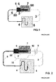
- Known heat transfer devices comprise an evaporator 2, collecting the heat from a heat source 7 and being connected to said heat source 7, a vapour transport line 3, which is the heat transport artery of the heat transfer device, a condenser 4, rejecting the heat and being connected to a heat sink 8, and a liquid transport line 5, which is the working fluid return artery in the device.
- these known heat transfer devices comprise, as distinguishing feature, a porous structure 6 in the evaporator 2.
- This structure 6 separates the phases of liquid 50 and vapor 60 in the device when it operates.
- This porous structure 6 can also have the function of the liquid returning pump if the fluid pressure drop in the device becomes lower than the porous structure 6 capillary potential, which is defined by the Young-Laplace equation.
- heat is taken from the heat source 7 by the evaporation of liquid from the porous structure 6. Due to the presence of positive temperature drop between the heat source 7 and the heat sink 8, vapour moves to the condenser 4 through the vapour transport line 3. Then, heat is released to the heat sink 8 by the process of vapour condensation in the condenser 4. Finally, the condensed liquid is returned to the evaporator 2 with the help of a porous structure-capillary pump or other type of pump (not shown). The loop in this device is therefore closed.
- the active temperature control of the heat source 7 can be performed by a heater 1 installed on the liquid part 50 of the evaporator 2 (see Figure 1 ).
- FIG. 2 Another known heat transfer device is that shown in Figure 2 , that comprises a three-way regulating valve 9 and a bypass line 10, the three-way regulating valve 9 being installed in the vapour transport line 3 (it can not be installed in the liquid transport line), and effecting the vapour (heat) flow redistribution between the condenser 4 and the bypass line 10.
- This method is passive and does not need any power source.
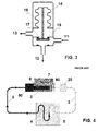
- the three-way regulating valve 9 of the heat transfer device of Figure 2 (see Figure 3 ) comprises one input 11, connected with the evaporator 2 outlet, and two outputs: the first output 12 is connected to the evaporator 2 inlet via the condenser 4 and the liquid line 5, and the second output 13 is connected to the evaporator 2 inlet via the bypass 10 line.
- the valve 9 comprises two chambers, an upper chamber 14 and a lower chamber 15, which are separated by gastight bellows 16, which are preferably metallic.
- the upper chamber 14 is not connected with the device working volume and it is usually filled with a predetermined amount of inert gas. The pressure value of this inert gas defines the minimum operational temperature of the evaporator 2.
- the lower chamber 15 is integrated in the heat transfer device, being usually filled during operation with vapour of the heat transfer device working fluid.
- the balance of pressures in the upper chamber 14 (inert gas) and in the lower chamber 15 (vapour) governs the direction of the mass vapour flow and the shearing of this flow between the two outputs 12, 13: first output 12 to condenser 4 and second output 13 to the bypass 10 line.
- the pressure in the device is a function of the temperature since the fluid in the circuit device is always in the saturated state (the two phases, vapour 60 and liquid 50 being in equilibrium).
- a thermal control device comprising a novel method of temperature control in the evaporator 2.
- the approach of the device of the invention simplifies current design of the three-way regulating valve 9 into a two-way regulating valve 20, eliminating the necessity of a bypass 10 line (see Figure 4 ).
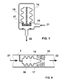
- the two-way regulating valve 20 in the device according to the invention comprises only one input 21 and one output 22 (see Figure 5 ): the input 21 is connected to the evaporator 2 outlet, and the output 22 is connected to the evaporator 2 inlet via the condenser 4 and the liquid transport line 5.
- valve 20 located in the vapour transport line 3
- the valve 20 can be also installed in the liquid transport line 5.
- the input 21 of the valve 20 is connected to the condenser 4 outlet, and the output 22 of the valve 20 is connected to the evaporator 2 inlet.
- the other elements are the same as the ones described above for the three-way regulating valve 9.
- An alternative variant of the two-way regulating valve 20 design, when the valve 20 is fully integrated into the vapour transport line 3, is shown in Figure 6 .
- This alternative design of the valve 20 is also valid in the case in which the mentioned valve 20 is integrated in the liquid transport line 5.
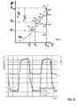
- the device of the invention Since the device of the invention is an evaporating-condensing thermal control device, it operates around the vapour-liquid saturation line SL. Two cycles are shown in Figure 6 : one marked with solid lines, and another one with dashed lines. The solid line cycle will be used in order to explain the cycle diagram. At position 100 liquid evaporates from the porous structure 6 in the evaporator 2 and moves to the evaporator 2 outlet (path 100-200). In this step, some vapour overheating can also take place. After that, vapor moves into the vapour line 3 (path 200-300), the temperature of vapor in the vapor line 3 being maintained constant (there is no heat exchange with the ambient) though pressure in the vapor line 3 is reduced.
- vapour is cooled up to saturation state (300-400), being condensed (400-500), the liquid condensate being further sub-cooled (500-600).
- Pressure is reduced on the way of liquid to evaporator 2 (600-700) due to friction losses in the conduit.
- the vapour phase is usually presented on the liquid side of the porous structure 6, liquid being in equilibrium with vapour (700-800). Liquid is superheated and pressure is further reduced during the filtration through the porous structure (800-900).
- the cycle is closed at vapor-liquid interface-meniscus where evaporation takes place (900-100).
- Point 900 in the diagram of Figure 6 corresponds to the liquid phase just under the meniscus, point 100 corresponding to the vapour phase just above the meniscus.
- the known two phase heat transfer loops operate following the solid line marked in the diagram of Figure 6 .
- a reduction in the temperature of the heat sink 8 leads to reducing the operational temperature Top (and corresponding operational pressure Pop) of the two phase heat transfer loop device.
- a thermal control device according to the invention comprising a two-way regulating valve 20 in the device circuit, this is not possible to happen.
- a thermal control device In a thermal control device according to the invention, if the operational pressure in the device becomes less than the backpressure of the inert gas in the upper chamber 14 of the two-way regulating valve 20 ( Figure 5 ), the stem 17 of valve 20 will close the vapour line 3 and circulation will be totally stopped through the two-way regulating valve 20 in the thermal control device. In a real situation, the stem 17 in the two-way regulating valve 20 will go down and close part of the cross section in the first output 12 of the mentioned valve 20 (see reference 12 in Figure 5 and reference 900 in the diagram of Figure 6 ).
- the two-way regulating valve 20 in the thermal control device of the invention plays the role of automatically adjusting the hydraulic resistance in the vapour line 3, keeping the operational temperature of the device Top constant, independently from the temperature in the condenser 4.
- the two-way regulating valve 20 is located in the vapour line 3 of the thermal control device, thus varying the hydraulic resistance of said vapour line 3.
- the two-way regulating valve 20 can also be located in the liquid line 5 of the thermal control device, thus varying the hydraulic resistance of the liquid line 5.
- the temperature of the inert gas in the upper part 14 of the valve 20 can vary with the temperature of the condenser 4, possibly leading to a less precise temperature control as that in the system with the valve 20 installed in the vapor transport line 3, since the temperature of vapor and consequently of the inert gas in the valve 20 are practically constant during the regulation.
- the valve 20, as it is described above, is a passive control element having a predetermined regulating temperature by the inert gas pressure in the upper chamber 14; however, a further heater on the body of the valve 20 can be installed, giving the possibility to change the set point (predetermined regulating temperature) during the device operation, therefore effecting an active control of the evaporator 2 operation temperature Top.
- the valve 20 can be charged with a two-phase fluid instead of an inert gas.
- the example of the thermal control device operation is shown on Figure 8 , showing experimental temperature data of the device of the invention, operating with temperature regulation set point at -32 °C.
- the experimentally measured values of temperatures of the thermal control device for condenser (T radiator), evaporator (T heat source) and ambient media (T space) are presented as a function of time.
- the device was filled with propylene as a working liquid and the regulating valve was charged by 2.3 Bar of argon to keep regulating temperature at -32°C.
- Ambient temperature has been varied during the experiment from - 70°C to 0 °C twice. Power 25 W has been constantly applied to the evaporator of the thermal control device by heat source. As it is clear from the graph the regulating valve did not allow the temperature of the heat source falling down below the set point of -32°C.
Landscapes
- Engineering & Computer Science (AREA)
- Life Sciences & Earth Sciences (AREA)
- General Engineering & Computer Science (AREA)
- Mechanical Engineering (AREA)
- Thermal Sciences (AREA)
- Physics & Mathematics (AREA)
- Sustainable Development (AREA)
- Environmental Sciences (AREA)
- Remote Sensing (AREA)
- Aviation & Aerospace Engineering (AREA)
- Toxicology (AREA)
- General Health & Medical Sciences (AREA)
- Health & Medical Sciences (AREA)
- Environmental & Geological Engineering (AREA)
- Biodiversity & Conservation Biology (AREA)
- Control Of Temperature (AREA)
Claims (6)
- Dispositif de régulation thermique pour réguler la température d'une source de chaleur (7) par un transfert de chaleur de la source de chaleur (7) vers un dissipateur de chaleur (8) au moyen d'une circulation de fluide dans le dispositif, ledit dispositif comprenant un évaporateur (2) collectant la chaleur de la source de chaleur (7), un condenseur (4) rejetant la chaleur vers le dissipateur de chaleur (8), et des conduites de transport (3, 5) reliant l'évaporateur (2) et le condenseur (4), le fluide circulant à travers lesdites conduites de transport (3, 5), dans lequel le dispositif comprend en outre une vanne (20) située dans l'une des conduites de transport (3, 5), ladite vanne (20) ouvrant et fermant la circulation du fluide dans la conduite de transport (3, 5), modifiant la résistance hydraulique de ladite conduite de transport (3, 5), la chute de pression dans le circuit des conduites de transport (3, 5), - vanne (20) - condenseur (4) étant telle qu'elle permet de maintenir la température d'opération de l'évaporateur (Top) sensiblement à une valeur prédéterminée, indépendante de la température du condensateur (Tc), caractérisé en ce que la vanne (20) comprend en outre un réchauffeur pour effectuer une régulation active de la température d'opération de l'évaporateur (Top).
- Dispositif de régulation thermique selon la revendication 1, dans lequel la vanne (20) est située dans une conduite de transport de vapeur (3) du dispositif, la température d'opération de l'évaporateur (Top) étant maintenue sensiblement constante.
- Dispositif de régulation thermique selon la revendication 2, dans lequel la vanne (20) comprend une seule entrée (21) et une seule sortie (22), l'entrée (21) étant reliée à la sortie de l'évaporateur (2), et la sortie (22) étant reliée à l'entrée de l'évaporateur (2) par l'intermédiaire du condenseur (4).
- Dispositif de régulation thermique selon la revendication 3, dans lequel l'entrée (21) et la sortie (22) sont reliées dans la vanne (20) au moyen d'une chambre inférieure (15) contenant de la vapeur.
- Dispositif de régulation thermique selon l'une quelconque des revendications précédentes, dans lequel la vanne (20) comprend en outre une chambre supérieure (14) comprenant un gaz inerte ou un liquide diphasique.
- Dispositif de régulation thermique selon la revendication 1, dans lequel la vanne (20) est située dans une conduite de transport de liquide (5) du dispositif.
Applications Claiming Priority (1)
| Application Number | Priority Date | Filing Date | Title |
|---|---|---|---|
| PCT/ES2010/070677 WO2012052573A1 (fr) | 2010-10-21 | 2010-10-21 | Dispositif de régulation thermique régulé par la pression |
Publications (2)
| Publication Number | Publication Date |
|---|---|
| EP2631183A1 EP2631183A1 (fr) | 2013-08-28 |
| EP2631183B1 true EP2631183B1 (fr) | 2015-01-21 |
Family
ID=44202174
Family Applications (1)
| Application Number | Title | Priority Date | Filing Date |
|---|---|---|---|
| EP10795404.2A Active EP2631183B1 (fr) | 2010-10-21 | 2010-10-21 | Dispositif de controle thermique commande par la pression |
Country Status (2)
| Country | Link |
|---|---|
| EP (1) | EP2631183B1 (fr) |
| WO (1) | WO2012052573A1 (fr) |
Cited By (1)
| Publication number | Priority date | Publication date | Assignee | Title |
|---|---|---|---|---|
| CN109287104A (zh) * | 2018-11-21 | 2019-01-29 | 山东大学 | 一种仿生蒸腾冷却自适应散热器 |
Families Citing this family (10)
| Publication number | Priority date | Publication date | Assignee | Title |
|---|---|---|---|---|
| CN103482086B (zh) * | 2013-08-12 | 2015-11-18 | 上海卫星工程研究所 | 高适应环路热管控温装置 |
| WO2015051799A1 (fr) * | 2013-10-09 | 2015-04-16 | Dantherm Cooling A/S | Échangeur thermique à microcanaux |
| ITTO20130873A1 (it) * | 2013-10-29 | 2015-04-30 | Alenia Aermacchi Spa | Circuito di raffreddamento/riscaldamento a fluido bifase con valvole di controllo del flusso sensibili alla temperatura |
| JP6390225B2 (ja) * | 2014-07-11 | 2018-09-19 | 富士通株式会社 | 冷却システム及び電子装置 |
| ITUB20150440A1 (it) * | 2015-05-05 | 2016-11-05 | Alenia Aermacchi Spa | Dispositivo di connessione/disconnessione per circuiti a fluido. |
| JP2020183814A (ja) * | 2019-04-26 | 2020-11-12 | トヨタ自動車株式会社 | 冷却装置 |
| EP4075088A4 (fr) * | 2019-12-09 | 2022-12-21 | Mitsubishi Electric Corporation | Appareil de refroidissement et satellite |
| JP7254249B2 (ja) | 2020-08-04 | 2023-04-07 | 三菱電機株式会社 | 冷却装置及び宇宙構造物 |
| CN113815908B (zh) * | 2020-11-05 | 2024-03-08 | 山东大学 | 一种智能保温的环路热管及其热控系统 |
| CN115406276B (zh) * | 2022-08-03 | 2024-08-23 | 上海格熵航天科技有限公司 | 一种单一热源工质消耗式圆柱形环路热管 |
Family Cites Families (4)
| Publication number | Priority date | Publication date | Assignee | Title |
|---|---|---|---|---|
| SU916956A1 (ru) * | 1980-07-16 | 1982-03-30 | Воронежский сельскохозяйственный институт им.К.Д.Глинки | Теплова труба |
| JPH0678871B2 (ja) * | 1987-10-12 | 1994-10-05 | 株式会社フジクラ | 給湯装置 |
| JP2006029672A (ja) * | 2004-07-15 | 2006-02-02 | Japan Aerospace Exploration Agency | 潜熱流体ループを使用する熱輸送装置 |
| EP2332839B1 (fr) * | 2008-10-02 | 2015-06-24 | Ibérica del Espacio, S.A. | Plateforme thermique modulaire d'engin spatial |
-
2010
- 2010-10-21 WO PCT/ES2010/070677 patent/WO2012052573A1/fr not_active Ceased
- 2010-10-21 EP EP10795404.2A patent/EP2631183B1/fr active Active
Cited By (1)
| Publication number | Priority date | Publication date | Assignee | Title |
|---|---|---|---|---|
| CN109287104A (zh) * | 2018-11-21 | 2019-01-29 | 山东大学 | 一种仿生蒸腾冷却自适应散热器 |
Also Published As
| Publication number | Publication date |
|---|---|
| WO2012052573A1 (fr) | 2012-04-26 |
| EP2631183A1 (fr) | 2013-08-28 |
Similar Documents
| Publication | Publication Date | Title |
|---|---|---|
| EP2631183B1 (fr) | Dispositif de controle thermique commande par la pression | |
| US9829253B2 (en) | Advanced control two phase heat transfer loop | |
| US9146059B2 (en) | Temperature actuated capillary valve for loop heat pipe system | |
| US20150001349A1 (en) | Cooling device for regulating the temperature of a heat source of a satellite, and method for producing the associated cooling device and satellite | |
| EP2347166B1 (fr) | Extraction d'un gaz non condensable d'un système de refroidissement subatmosphérique | |
| US9179575B1 (en) | MEMS based device for phase-change autonomous transport of heat (PATH) | |
| US20120198859A1 (en) | Thermal control device | |
| US10337803B2 (en) | Dual-phase fluid heating/cooling circuit provided with temperature-sensing flow control valves | |
| EP3106393B1 (fr) | Rejet de chaleur variable utilisant un caloduc échangeur de chaleur | |
| JP2006029672A (ja) | 潜熱流体ループを使用する熱輸送装置 | |
| US11525636B2 (en) | Method and system for stabilizing loop heat pipe operation with a controllable condenser bypass | |
| RU2487063C2 (ru) | Система терморегулирования приборного отсека посадочного лунного модуля | |
| RU2854552C1 (ru) | Терморегулирующее устройство на базе контурной тепловой трубы | |
| EP2639162B1 (fr) | Element de chauffage de demarrage pour dispositif de controle thermique | |
| Goncharov et al. | Loop heat pipe for high-precision satellite thermal control | |
| CN105806111B (zh) | 一种基于超热导原理的换热系统 | |
| Jie et al. | Experimental investigation on a novel method for set point temperature controlling of the active two-phase cooling loop | |
| Mishkinis et al. | Low power and low temperature LHP for thermal control of rovers | |
| Diebold et al. | Non-Integrated Hot Reservoir Variable Conductance Heat Pipes | |
| WO2015048973A1 (fr) | Système de refroidissement doté d'un thermosiphon, utilisation et procédé d'exploitation d'un tel système | |
| Yun et al. | Thermal performance of multi-evaporator hybrid loop heat pipe (ME-HLHP) with a liquid cooled shield (LCS) | |
| Mishkinis et al. | Development of Miniature Heat Switch Temperature Controller based on variable conductance LHP | |
| Singh et al. | Innovative multi-environment, multimode thermal control system | |
| US20240199239A1 (en) | Cooling device and space structure | |
| Yu et al. | Research on adaptive thermal control system of space optical remote sensor |
Legal Events
| Date | Code | Title | Description |
|---|---|---|---|
| PUAI | Public reference made under article 153(3) epc to a published international application that has entered the european phase |
Free format text: ORIGINAL CODE: 0009012 |
|
| 17P | Request for examination filed |
Effective date: 20130517 |
|
| AK | Designated contracting states |
Kind code of ref document: A1 Designated state(s): AL AT BE BG CH CY CZ DE DK EE ES FI FR GB GR HR HU IE IS IT LI LT LU LV MC MK MT NL NO PL PT RO RS SE SI SK SM TR |
|
| DAX | Request for extension of the european patent (deleted) | ||
| RAP1 | Party data changed (applicant data changed or rights of an application transferred) |
Owner name: IBERICA DEL ESPACIO, S.A. |
|
| GRAP | Despatch of communication of intention to grant a patent |
Free format text: ORIGINAL CODE: EPIDOSNIGR1 |
|
| RIC1 | Information provided on ipc code assigned before grant |
Ipc: B64G 1/50 20060101AFI20140616BHEP Ipc: F28D 15/06 20060101ALI20140616BHEP Ipc: F28F 27/02 20060101ALN20140616BHEP Ipc: F28D 15/02 20060101ALI20140616BHEP |
|
| INTG | Intention to grant announced |
Effective date: 20140704 |
|
| GRAS | Grant fee paid |
Free format text: ORIGINAL CODE: EPIDOSNIGR3 |
|
| GRAA | (expected) grant |
Free format text: ORIGINAL CODE: 0009210 |
|
| AK | Designated contracting states |
Kind code of ref document: B1 Designated state(s): AL AT BE BG CH CY CZ DE DK EE ES FI FR GB GR HR HU IE IS IT LI LT LU LV MC MK MT NL NO PL PT RO RS SE SI SK SM TR |
|
| REG | Reference to a national code |
Ref country code: GB Ref legal event code: FG4D |
|
| REG | Reference to a national code |
Ref country code: CH Ref legal event code: EP |
|
| REG | Reference to a national code |
Ref country code: IE Ref legal event code: FG4D |
|
| REG | Reference to a national code |
Ref country code: DE Ref legal event code: R096 Ref document number: 602010022016 Country of ref document: DE Effective date: 20150305 |
|
| REG | Reference to a national code |
Ref country code: AT Ref legal event code: REF Ref document number: 709037 Country of ref document: AT Kind code of ref document: T Effective date: 20150315 |
|
| REG | Reference to a national code |
Ref country code: NL Ref legal event code: VDEP Effective date: 20150121 |
|
| REG | Reference to a national code |
Ref country code: AT Ref legal event code: MK05 Ref document number: 709037 Country of ref document: AT Kind code of ref document: T Effective date: 20150121 |
|
| REG | Reference to a national code |
Ref country code: LT Ref legal event code: MG4D |
|
| PG25 | Lapsed in a contracting state [announced via postgrant information from national office to epo] |
Ref country code: LT Free format text: LAPSE BECAUSE OF FAILURE TO SUBMIT A TRANSLATION OF THE DESCRIPTION OR TO PAY THE FEE WITHIN THE PRESCRIBED TIME-LIMIT Effective date: 20150121 Ref country code: SE Free format text: LAPSE BECAUSE OF FAILURE TO SUBMIT A TRANSLATION OF THE DESCRIPTION OR TO PAY THE FEE WITHIN THE PRESCRIBED TIME-LIMIT Effective date: 20150121 Ref country code: FI Free format text: LAPSE BECAUSE OF FAILURE TO SUBMIT A TRANSLATION OF THE DESCRIPTION OR TO PAY THE FEE WITHIN THE PRESCRIBED TIME-LIMIT Effective date: 20150121 Ref country code: ES Free format text: LAPSE BECAUSE OF FAILURE TO SUBMIT A TRANSLATION OF THE DESCRIPTION OR TO PAY THE FEE WITHIN THE PRESCRIBED TIME-LIMIT Effective date: 20150121 Ref country code: HR Free format text: LAPSE BECAUSE OF FAILURE TO SUBMIT A TRANSLATION OF THE DESCRIPTION OR TO PAY THE FEE WITHIN THE PRESCRIBED TIME-LIMIT Effective date: 20150121 Ref country code: BG Free format text: LAPSE BECAUSE OF FAILURE TO SUBMIT A TRANSLATION OF THE DESCRIPTION OR TO PAY THE FEE WITHIN THE PRESCRIBED TIME-LIMIT Effective date: 20150421 Ref country code: NO Free format text: LAPSE BECAUSE OF FAILURE TO SUBMIT A TRANSLATION OF THE DESCRIPTION OR TO PAY THE FEE WITHIN THE PRESCRIBED TIME-LIMIT Effective date: 20150421 |
|
| PG25 | Lapsed in a contracting state [announced via postgrant information from national office to epo] |
Ref country code: NL Free format text: LAPSE BECAUSE OF FAILURE TO SUBMIT A TRANSLATION OF THE DESCRIPTION OR TO PAY THE FEE WITHIN THE PRESCRIBED TIME-LIMIT Effective date: 20150121 Ref country code: RS Free format text: LAPSE BECAUSE OF FAILURE TO SUBMIT A TRANSLATION OF THE DESCRIPTION OR TO PAY THE FEE WITHIN THE PRESCRIBED TIME-LIMIT Effective date: 20150121 Ref country code: IS Free format text: LAPSE BECAUSE OF FAILURE TO SUBMIT A TRANSLATION OF THE DESCRIPTION OR TO PAY THE FEE WITHIN THE PRESCRIBED TIME-LIMIT Effective date: 20150521 Ref country code: AT Free format text: LAPSE BECAUSE OF FAILURE TO SUBMIT A TRANSLATION OF THE DESCRIPTION OR TO PAY THE FEE WITHIN THE PRESCRIBED TIME-LIMIT Effective date: 20150121 Ref country code: GR Free format text: LAPSE BECAUSE OF FAILURE TO SUBMIT A TRANSLATION OF THE DESCRIPTION OR TO PAY THE FEE WITHIN THE PRESCRIBED TIME-LIMIT Effective date: 20150422 Ref country code: PL Free format text: LAPSE BECAUSE OF FAILURE TO SUBMIT A TRANSLATION OF THE DESCRIPTION OR TO PAY THE FEE WITHIN THE PRESCRIBED TIME-LIMIT Effective date: 20150121 Ref country code: LV Free format text: LAPSE BECAUSE OF FAILURE TO SUBMIT A TRANSLATION OF THE DESCRIPTION OR TO PAY THE FEE WITHIN THE PRESCRIBED TIME-LIMIT Effective date: 20150121 |
|
| REG | Reference to a national code |
Ref country code: FR Ref legal event code: PLFP Year of fee payment: 6 Ref country code: DE Ref legal event code: R097 Ref document number: 602010022016 Country of ref document: DE |
|
| PG25 | Lapsed in a contracting state [announced via postgrant information from national office to epo] |
Ref country code: SK Free format text: LAPSE BECAUSE OF FAILURE TO SUBMIT A TRANSLATION OF THE DESCRIPTION OR TO PAY THE FEE WITHIN THE PRESCRIBED TIME-LIMIT Effective date: 20150121 Ref country code: RO Free format text: LAPSE BECAUSE OF FAILURE TO SUBMIT A TRANSLATION OF THE DESCRIPTION OR TO PAY THE FEE WITHIN THE PRESCRIBED TIME-LIMIT Effective date: 20150121 Ref country code: DK Free format text: LAPSE BECAUSE OF FAILURE TO SUBMIT A TRANSLATION OF THE DESCRIPTION OR TO PAY THE FEE WITHIN THE PRESCRIBED TIME-LIMIT Effective date: 20150121 Ref country code: CZ Free format text: LAPSE BECAUSE OF FAILURE TO SUBMIT A TRANSLATION OF THE DESCRIPTION OR TO PAY THE FEE WITHIN THE PRESCRIBED TIME-LIMIT Effective date: 20150121 Ref country code: EE Free format text: LAPSE BECAUSE OF FAILURE TO SUBMIT A TRANSLATION OF THE DESCRIPTION OR TO PAY THE FEE WITHIN THE PRESCRIBED TIME-LIMIT Effective date: 20150121 |
|
| PLBE | No opposition filed within time limit |
Free format text: ORIGINAL CODE: 0009261 |
|
| STAA | Information on the status of an ep patent application or granted ep patent |
Free format text: STATUS: NO OPPOSITION FILED WITHIN TIME LIMIT |
|
| 26N | No opposition filed |
Effective date: 20151022 |
|
| PG25 | Lapsed in a contracting state [announced via postgrant information from national office to epo] |
Ref country code: IT Free format text: LAPSE BECAUSE OF FAILURE TO SUBMIT A TRANSLATION OF THE DESCRIPTION OR TO PAY THE FEE WITHIN THE PRESCRIBED TIME-LIMIT Effective date: 20150121 |
|
| PG25 | Lapsed in a contracting state [announced via postgrant information from national office to epo] |
Ref country code: SI Free format text: LAPSE BECAUSE OF FAILURE TO SUBMIT A TRANSLATION OF THE DESCRIPTION OR TO PAY THE FEE WITHIN THE PRESCRIBED TIME-LIMIT Effective date: 20150121 |
|
| PG25 | Lapsed in a contracting state [announced via postgrant information from national office to epo] |
Ref country code: LU Free format text: LAPSE BECAUSE OF FAILURE TO SUBMIT A TRANSLATION OF THE DESCRIPTION OR TO PAY THE FEE WITHIN THE PRESCRIBED TIME-LIMIT Effective date: 20151021 |
|
| REG | Reference to a national code |
Ref country code: CH Ref legal event code: PL |
|
| PG25 | Lapsed in a contracting state [announced via postgrant information from national office to epo] |
Ref country code: MC Free format text: LAPSE BECAUSE OF FAILURE TO SUBMIT A TRANSLATION OF THE DESCRIPTION OR TO PAY THE FEE WITHIN THE PRESCRIBED TIME-LIMIT Effective date: 20150121 |
|
| REG | Reference to a national code |
Ref country code: IE Ref legal event code: MM4A |
|
| PG25 | Lapsed in a contracting state [announced via postgrant information from national office to epo] |
Ref country code: CH Free format text: LAPSE BECAUSE OF NON-PAYMENT OF DUE FEES Effective date: 20151031 Ref country code: LI Free format text: LAPSE BECAUSE OF NON-PAYMENT OF DUE FEES Effective date: 20151031 |
|
| REG | Reference to a national code |
Ref country code: FR Ref legal event code: PLFP Year of fee payment: 7 |
|
| PG25 | Lapsed in a contracting state [announced via postgrant information from national office to epo] |
Ref country code: IE Free format text: LAPSE BECAUSE OF NON-PAYMENT OF DUE FEES Effective date: 20151021 |
|
| PG25 | Lapsed in a contracting state [announced via postgrant information from national office to epo] |
Ref country code: HU Free format text: LAPSE BECAUSE OF FAILURE TO SUBMIT A TRANSLATION OF THE DESCRIPTION OR TO PAY THE FEE WITHIN THE PRESCRIBED TIME-LIMIT; INVALID AB INITIO Effective date: 20101021 Ref country code: SM Free format text: LAPSE BECAUSE OF FAILURE TO SUBMIT A TRANSLATION OF THE DESCRIPTION OR TO PAY THE FEE WITHIN THE PRESCRIBED TIME-LIMIT Effective date: 20150121 |
|
| PG25 | Lapsed in a contracting state [announced via postgrant information from national office to epo] |
Ref country code: CY Free format text: LAPSE BECAUSE OF FAILURE TO SUBMIT A TRANSLATION OF THE DESCRIPTION OR TO PAY THE FEE WITHIN THE PRESCRIBED TIME-LIMIT Effective date: 20150121 |
|
| PG25 | Lapsed in a contracting state [announced via postgrant information from national office to epo] |
Ref country code: MT Free format text: LAPSE BECAUSE OF FAILURE TO SUBMIT A TRANSLATION OF THE DESCRIPTION OR TO PAY THE FEE WITHIN THE PRESCRIBED TIME-LIMIT Effective date: 20150121 |
|
| REG | Reference to a national code |
Ref country code: FR Ref legal event code: PLFP Year of fee payment: 8 |
|
| PG25 | Lapsed in a contracting state [announced via postgrant information from national office to epo] |
Ref country code: TR Free format text: LAPSE BECAUSE OF FAILURE TO SUBMIT A TRANSLATION OF THE DESCRIPTION OR TO PAY THE FEE WITHIN THE PRESCRIBED TIME-LIMIT Effective date: 20150121 Ref country code: MK Free format text: LAPSE BECAUSE OF FAILURE TO SUBMIT A TRANSLATION OF THE DESCRIPTION OR TO PAY THE FEE WITHIN THE PRESCRIBED TIME-LIMIT Effective date: 20150121 Ref country code: PT Free format text: LAPSE BECAUSE OF FAILURE TO SUBMIT A TRANSLATION OF THE DESCRIPTION OR TO PAY THE FEE WITHIN THE PRESCRIBED TIME-LIMIT Effective date: 20150121 |
|
| REG | Reference to a national code |
Ref country code: FR Ref legal event code: PLFP Year of fee payment: 9 |
|
| PG25 | Lapsed in a contracting state [announced via postgrant information from national office to epo] |
Ref country code: AL Free format text: LAPSE BECAUSE OF FAILURE TO SUBMIT A TRANSLATION OF THE DESCRIPTION OR TO PAY THE FEE WITHIN THE PRESCRIBED TIME-LIMIT Effective date: 20150121 |
|
| PGFP | Annual fee paid to national office [announced via postgrant information from national office to epo] |
Ref country code: DE Payment date: 20241024 Year of fee payment: 15 |
|
| PGFP | Annual fee paid to national office [announced via postgrant information from national office to epo] |
Ref country code: BE Payment date: 20241022 Year of fee payment: 15 |
|
| PGFP | Annual fee paid to national office [announced via postgrant information from national office to epo] |
Ref country code: GB Payment date: 20241023 Year of fee payment: 15 |
|
| PGFP | Annual fee paid to national office [announced via postgrant information from national office to epo] |
Ref country code: FR Payment date: 20241023 Year of fee payment: 15 |