EP2631396A2 - Leichte Schutzüberdachung und Montageverfahren einer solchen Schutzüberdachung - Google Patents
Leichte Schutzüberdachung und Montageverfahren einer solchen Schutzüberdachung Download PDFInfo
- Publication number
- EP2631396A2 EP2631396A2 EP13156598.8A EP13156598A EP2631396A2 EP 2631396 A2 EP2631396 A2 EP 2631396A2 EP 13156598 A EP13156598 A EP 13156598A EP 2631396 A2 EP2631396 A2 EP 2631396A2
- Authority
- EP
- European Patent Office
- Prior art keywords
- central mast
- frame
- locking
- support assembly
- fabric
- Prior art date
- Legal status (The legal status is an assumption and is not a legal conclusion. Google has not performed a legal analysis and makes no representation as to the accuracy of the status listed.)
- Withdrawn
Links
- 238000000034 method Methods 0.000 title claims abstract description 16
- 239000004744 fabric Substances 0.000 claims abstract description 38
- 230000002093 peripheral effect Effects 0.000 claims abstract description 16
- 230000000903 blocking effect Effects 0.000 claims description 6
- 239000007787 solid Substances 0.000 description 4
- 239000000470 constituent Substances 0.000 description 2
- 238000003466 welding Methods 0.000 description 2
- 230000000712 assembly Effects 0.000 description 1
- 238000000429 assembly Methods 0.000 description 1
- 239000011324 bead Substances 0.000 description 1
- 238000010276 construction Methods 0.000 description 1
- 230000000694 effects Effects 0.000 description 1
- 238000009434 installation Methods 0.000 description 1
- 239000000463 material Substances 0.000 description 1
- 238000004806 packaging method and process Methods 0.000 description 1
- 230000000284 resting effect Effects 0.000 description 1
- 238000007789 sealing Methods 0.000 description 1
- 239000000126 substance Substances 0.000 description 1
Images



Classifications
-
- E—FIXED CONSTRUCTIONS
- E04—BUILDING
- E04H—BUILDINGS OR LIKE STRUCTURES FOR PARTICULAR PURPOSES; SWIMMING OR SPLASH BATHS OR POOLS; MASTS; FENCING; TENTS OR CANOPIES, IN GENERAL
- E04H15/00—Tents or canopies, in general
- E04H15/26—Centre-pole supported tents
Definitions
- the present invention relates to a lightweight shelter comprising a support assembly of a roof element comprising a frame and a fabric to be stretched between the frame and the support assembly and the associated mounting method.
- This shelter 101 according to the state of the art is represented on the figure 1 and comprises a support assembly 102, a roof element comprising a quadrilateral-shaped frame 103 and a wire 104 fixed by its outer peripheral portion to the frame 103 and intended to be stretched between said frame 103 and the support assembly 102.
- Said support assembly 102 comprises a central mast 105, a hinge 106 mounted slidably, able to be locked on said central mast 105 and arranged to receive the central portion of said web 104, a flange 107 fixed on the upper part of said central mast 105, said flange 107 comprising a set of radial pulleys 108 each capable of receiving a cable 109, and a tensioning ring 110 slidably mounted and able to be locked on said central mast 105.
- Each cable 109 passes over one of the pulleys 108 and has a first end attached to the tension ring 110 and a second end attached to the frame 103, said tension ring 110 of the support assembly 102 being locked to the central mast 105 in a position such as cables 109 are stretched.
- the assembly of this shelter takes place in the following way.
- the support assembly 102 comprising the central mast 105, the hoop 106, the flange 107, the tension ring 110 and the cables 109, is erected.
- the frame 103 is then arranged or assembled around said support assembly 102.
- the second end of each cable 109 of the support assembly 102 is then fixed to fixing points 111 provided on the frame 103.
- the fabric 104 is fixed on the frame 103 by its outer periphery and on the circle 106 by its inner periphery defined by its central part.
- the tension ring 110 is pulled downwardly, on the one hand, to lift the frame 103 and, on the other hand, tension the fabric 104 by pushing the ring 106 downwards. Finally, once the desired fabric tension obtained, the tension ring 110 is locked on the central mast 105 in the desired final position.
- the support assembly 102 according to the state of the art has a number of disadvantages. Indeed, because of its number of constituent elements and their complexity, this support assembly 102 is particularly difficult and expensive to achieve and implement.
- the purpose of the present invention is therefore to overcome the aforementioned drawbacks and to provide a lightweight shelter of the central mast type comprising a support assembly of a roof element, whose structure is such that, on the one hand, the transport and the mounting of said shelter are advantageously easier due in particular to the reduced length of different parts and, on the other hand, the assemblies of the various elements between them do not require the use of specific tools and qualified personnel while being perfectly secure.
- a lightweight shelter comprising a roof element supported by a support assembly and formed by a frame and a fabric fixed by its outer peripheral edge on said frame and stretched between said frame and the support assembly , said support assembly comprising a central mast, connecting means slidably mounted on said central mast and arranged to receive the inner peripheral edge of the fabric and to be locked on said central mast after tensioning said fabric, a flange slidably mounted on said central mast and arranged to be locked at the upper end of the central mast by locking means, and a plurality of cables whose one end is fixed on said flange the other being fixed to the frame, said central mast being telescopic and having at least one tubular lower member fixed to the ground and an upper member arranged to slide inside said lower member between a "retracted position” in which said upper member is disposed wholly or substantially in said lower member, and an "extended position” in which said upper member is disposed substantially out of said lower member, said upper member being locked in "extended position" by at least one
- the blocking means advantageously comprise at least one locking member adapted to cooperate with a first orifice entirely passing through the lower end of the upper element and in that the said locking member comprises two ferrules arranged to to be fixed around the junction of the lower and upper elements and a bolt secured to one of the ferrules and able to cooperate simultaneously with said first orifice of the upper element and an orifice of the other ferrule, said stud coming into the " output position ", resting on the annular face of the upper end of the lower element of the central mast.
- the locking means comprise an abutment disposed at the upper end of the upper element, a second orifice entirely passing through the upper end of the upper element and disposed under said abutment, and a locking adapted to cooperate with said second orifice.
- the lightweight shelter preferably comprises a rainwater collector on the central mast around the connecting means.
- the mounting method comprises a step of removing the fabric on the ground around the central mast before the vertical fixing step of the central mast.
- the mounting method comprises an intermediate lifting step of the frame-cable-flange assembly before the step of fixing the fabric.
- the mounting method comprises a step of setting up a rainwater collector after the step of locking the connecting means on the central mast.
- the mounting method comprises a step of producing a concrete block before the step of erection of the support assembly.
- the fastening of the fabric can be carried out before fixing the free end of the cables to the fixing points of the frame.
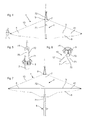
- a light shelter 1 comprising a support assembly 2, a roof element 3 comprising a frame 4 in the form of a polygon and a web 5 fixed by its outer peripheral edge on the frame 4 and intended to be stretched between said frame 4 and the support assembly 2, said fabric 2 is provided in its central part with an orifice whose edge defines the inner peripheral edge of the fabric 2.
- This lightweight shelter 4 further comprises a rainwater collector 6.
- said support element 2 comprises a central mast 7, connecting means 8 (see FIG. figure 9 ) slidably mounted on said central mast 7 and arranged to be locked on said central mast 7, a flange 9 slidably mounted on said central mast 7 and arranged to be fixed to the upper end of said central mast 7, and a plurality of cables 10 one of whose ends is fixed on said flange 9, the other being intended to be fixed on the frame 4.
- this support element 2 has few parts and is therefore easy and quick to put in place. artwork.
- the central mast 7 is intended to be fixed on a solid mass (not shown) by fastening means (not shown) such as sealing butts or any other similar means providing the same effects such as chemical or self-expanding pins by example.
- the central mast 7 is telescopic in order to limit the dimensions of the packages and the transport costs of the light shelter 1 before assembly.
- the central mast 7 comprises at least one lower element 71 fixed on said solid mass and an upper element 72 arranged to slide inside said lower element 71 between a "retracted position” in which said upper element 72 is disposed entirely or for the most part in said lower element 71 (see figure 2 ), and an "output position” in which said upper member 72 is disposed largely out of said lower member 71 (see FIG. figure 10 ). It is well understood that, in the "outward position", it is necessary, to block the lower and upper elements 71, 72 between them, that the upper element 72 is still its lower end in the upper end of said lower element 71 (see FIG.
- the support element 2 comprises, with reference to the figure 8 , locking means comprising at least one locking member 11 adapted to cooperate with a first orifice 73 completely passing through the lower end of the upper member 72.
- Said locking member 11 preferably comprises two rings 111, 112 arranged to be fixed around the junction of the lower and upper elements 71, 72 and a pin 113 integral with one of the rings 111 and able to cooperate simultaneously with said first orifice 73 of the upper member 72 and an orifice 114 of the other ferrule 112
- the stud 113 bears on the annular face of the upper end of the lower element 71 of the central mast 7.
- the pin 113 of the locking member 11 does not rest on the annular face of the upper end of the lower member 71 of the central mast 7 but each cooperate with orifices made in the upper end of the lower element 71 of said central mast 7.
- this configuration is not advantageous because it requires a angular positioning of the upper member 72 relative to the lower member 71 during its assembly.
- the locking member 11 may be replaced, without departing from the scope of the present invention, by at least one quick locking means snap type secured to the lower end of the element upper 72 and adapted either to bear against the annular face of the upper end of the lower element 71 of the central mast 7, or to cooperate with orifices made in the upper end of the lower element 71 of said central mast 7.
- the upper element 72 is provided at its upper end with a stop 74 and a second orifice 75 completely through the upper end of the upper element 72 and disposed under said stop 74.
- the latter is advantageously a closing disc the upper element 72 whose dimensions are greater than those of the horizontal section of said upper element 72.
- the abutment 74 and the second orifice 75 form, with at least one locking member 12 preferably of the spindle type adapted to cooperate with said second orifice 75, locking means for locking in position the flange 9 at the upper end of the upper element 72.
- the central mast 7 is preferably a hollow tube connected in the lower part to a not shown rainwater drainage device.
- this central mast 7 has an orifice 76 adapted to cooperate with the rainwater collector 6 to discharge to said rainwater evacuation device received on the fabric 5 of the roof element 3.
- the connecting means 8 are furthermore arranged to to receive the inner peripheral edge of the fabric 5.
- these connecting means 8 are similar to the connecting means described in the European patent application EP 1,905,926 filed at the plaintiff's.
- the fabric 5 comprises along its inner peripheral edge a ring 51, that is to say a bead.
- This ring 51 is formed by a ring taken in a fold of said web 5, said ring being for example made of natural or synthetic rope.
- the connecting means 8 comprise a hoop 81, that is to say an annular portion, intended to receive on its outer surface the rod 51 of the cloth 5.
- This hoop 81 is provided at its upper end with a stop 82 extending radially outwards, fixed to the hoop 81 for example by welding, and a locking ring 83 which, in the position where the fabric 5 is mounted, is interposed between the rod 51 and the stop 82 thus ensuring the locking of the ring 51.
- the connecting means 8 also comprise a ferrule 84, preferably cylindrical, for sliding said connecting means 8 along the central mast 7 and joining means 85 connecting the ferrule 84 to the core 81, these connecting means 85 being for example in the form of a plurality of radial wings (See figure 10 ).
- the flange 9 is preferably a ferrule-type tubular element slidably mounted on the central mast 7 to a "locking position" in which the flange 9 is locked at the upper end of the upper element 72 of said central mast 7 between the stop 74 and the locking member 121 disposed in the second orifice 75.
- the locking member 121 is replaced by at least one rapid locking means of the latching type integral with the flange 9 and adapted to cooperate with the second orifice 75 formed in the upper end of the upper element of said central mast 7.
- this configuration is disadvantageous because it requires positioning angular of the flange 9 during its assembly.
- the light shelter 1 also comprises a roof element 3 comprising a frame 4 disposed around the central mast 7 of the support assembly 2, consisting of a spar 41 assembled to each other, having a global shape of regular polygon and being suspended by the cables 10 of the support assembly 2 connected only to each of the vertices of said frame 4 to limit the overhangs.
- the frame 4 will advantageously have an even number of vertices at least equal to six.
- the longitudinal members 41 each preferably comprise a prestressing means not shown for putting each beam 41 in a state tension, said tension is opposite to that which will be exerted by the web 5 when the latter will be stretched.
- the present invention also relates to the mounting method of said light shelter 1. This assembly proceeds in the following manner.
- the fabric 5 is placed on the ground so that the mass to receive the central mast 7 of the support assembly 2 appears in the orifice of the fabric 5.
- the support assembly 2 is erected by placing the central mast 7 on the solid mass, beforehand the connecting means 8 and the flange 9 are slidably mounted on said central mast 7, the cables 59 being advantageously fixed at one of their ends to the flange 9.
- the central mast 7 is telescopic and comprises at least one lower element 71 fixed on said solid mass and an element upper 72 arranged to slide inside said lower member 71.
- the next step is to assemble and set up the frame 4 around said support assembly 2, as shown in FIG. figure 3 .
- it brings the frame elements 4 formed of longitudinal members 41. These are placed on the ground or trestles and the frame 4 is mounted on site by fixing - for example by bolting - the ends of longitudinal members 41 between them.
- prestressing means may be placed on each spar 41 of said frame 4, especially for frames 4 large.
- the frame assembly 4-cables 10-flange 9 is then slightly raised using a suitable lifting means such as a crane whose hook is connected to said flange 9, so that it is maintained at a height sufficient to allow easy placement of the fabric 5.
- the fabric 5 is fixed substantially sealingly on the frame 4 by any known means and in particular bonding, welding, clipping or by a fastening device similar to that described in the European patent EP 0 277 073 issued in the name of the plaintiff.
- a fastening device similar to that described in the European patent EP 0 277 073 issued in the name of the plaintiff.
- the assembly frame 4-canvas 5-cables 10-flange 9-upper member 72 is raised until the upper member 72 is in "extended position" and its first orifice 73 comes above the annular face the upper end of the lower element 71 of the central mast 7.
- the locking member 11 is then arranged so that its rings 111, 112 are disposed on either side of the junction zone of the lower elements and 71, 72 of the central mast 7, and that its pin 113 cooperates simultaneously with said first orifice 73 of the upper member 72 and the orifice 114 of the ferrule 112 and is supported on the annular face of the upper end of the lower element 71 of the central mast 7.
- the connecting means 8 are then fixed on the inner peripheral edge of the fabric 5 by interposing the locking ring 83 between the ring 51 of the fabric 5 and the stop 83 thus ensuring the locking of the ring 51. It is then sufficient to pull the connecting means 8 downwards until the desired tension of the web 5 is obtained. This can be done simply, as shown in FIG. figure 10 , by fastening a cable puller 13 for example of the type TIRFOR (registered trademark) on the lower end of the lower element 71 of the central mast 7 and connecting the means of connection 8 to the cable puller 13 by a cable 14.
- a cable puller 13 for example of the type TIRFOR (registered trademark)
- the connecting means 8 are locked in position on the lower element 71 of the central mast 7 by means of, for example, an axis 15 traversing simultaneously the connecting means 8 and the central mast 7, as shown on the figure 11 .
- the light shelter 1 mounted then has the appearance illustrated on the figure 13 .
- the fixing of the fabric 5 can be performed before fixing the free end of the cables 10 to the frame 4.
- this assembly may include a step of producing a concrete block before erecting the support assembly 2.
- the support element 2 of a roof element 3 according to the invention and the light shelter 1 comprising such a support element 2 may advantageously be installed on any type of site whatever the climatic conditions and access.
- the structure of the lightweight shelter 1 according to the invention is lightweight construction, simple and fast, while ensuring a remarkable mechanical strength.
Landscapes
- Engineering & Computer Science (AREA)
- Architecture (AREA)
- Civil Engineering (AREA)
- Structural Engineering (AREA)
- Tents Or Canopies (AREA)
- Buildings Adapted To Withstand Abnormal External Influences (AREA)
Applications Claiming Priority (1)
| Application Number | Priority Date | Filing Date | Title |
|---|---|---|---|
| FR1200536A FR2987390B1 (fr) | 2012-02-23 | 2012-02-23 | Procede de montage d'un abri leger |
Publications (2)
| Publication Number | Publication Date |
|---|---|
| EP2631396A2 true EP2631396A2 (de) | 2013-08-28 |
| EP2631396A3 EP2631396A3 (de) | 2014-12-31 |
Family
ID=47739166
Family Applications (1)
| Application Number | Title | Priority Date | Filing Date |
|---|---|---|---|
| EP13156598.8A Withdrawn EP2631396A3 (de) | 2012-02-23 | 2013-02-25 | Leichte Schutzüberdachung und Montageverfahren einer solchen Schutzüberdachung |
Country Status (2)
| Country | Link |
|---|---|
| EP (1) | EP2631396A3 (de) |
| FR (1) | FR2987390B1 (de) |
Citations (3)
| Publication number | Priority date | Publication date | Assignee | Title |
|---|---|---|---|---|
| EP0277073A2 (de) | 1987-01-30 | 1988-08-03 | Jean Dalo | Befestigungsvorrichtung für den Rand eines ausgespannten Tuches, insbesondere anwendbar zur Befestigung des unteren Randes eines Zelttuches und mit einer solchen Vorrichtung versehene Schutzhütte |
| EP1905926A1 (de) | 2006-09-28 | 2008-04-02 | Dalo Frères | Unterstand |
| EP1932983A1 (de) | 2006-12-12 | 2008-06-18 | Société Dalo Frères | Halterungseinheit für ein Dachelement, Unterstand, der eine solche Halterungseinheit umfasst und Montageverfahren eines solchen Unterstands |
Family Cites Families (1)
| Publication number | Priority date | Publication date | Assignee | Title |
|---|---|---|---|---|
| FR2957960B1 (fr) * | 2010-03-26 | 2012-08-31 | Catherine Dalo | Ensemble support d'un element de toiture et abri leger comprenant un tel ensemble support |
-
2012
- 2012-02-23 FR FR1200536A patent/FR2987390B1/fr not_active Expired - Fee Related
-
2013
- 2013-02-25 EP EP13156598.8A patent/EP2631396A3/de not_active Withdrawn
Patent Citations (3)
| Publication number | Priority date | Publication date | Assignee | Title |
|---|---|---|---|---|
| EP0277073A2 (de) | 1987-01-30 | 1988-08-03 | Jean Dalo | Befestigungsvorrichtung für den Rand eines ausgespannten Tuches, insbesondere anwendbar zur Befestigung des unteren Randes eines Zelttuches und mit einer solchen Vorrichtung versehene Schutzhütte |
| EP1905926A1 (de) | 2006-09-28 | 2008-04-02 | Dalo Frères | Unterstand |
| EP1932983A1 (de) | 2006-12-12 | 2008-06-18 | Société Dalo Frères | Halterungseinheit für ein Dachelement, Unterstand, der eine solche Halterungseinheit umfasst und Montageverfahren eines solchen Unterstands |
Also Published As
| Publication number | Publication date |
|---|---|
| FR2987390A1 (fr) | 2013-08-30 |
| FR2987390B1 (fr) | 2016-01-01 |
| EP2631396A3 (de) | 2014-12-31 |
Similar Documents
| Publication | Publication Date | Title |
|---|---|---|
| EP2041429B1 (de) | Vorrichtung und verfahren zur schnellen demontage des rotors und der gondel von einem windturbinenmast und mit einer solchen vorrichtung ausgestattete windturbine | |
| EP2369097A1 (de) | Halterungseinheit für ein Dachelement und leichter Unterstand mit einer solchen Halterungseinheit | |
| EP0009451B1 (de) | Teleskopmast | |
| EP0379567A1 (de) | Zusammenklappbares schutzdach, wie schirm, schutzdach für marktstände, camping oder ähnliches. | |
| WO2016023110A1 (fr) | Ombrières et auvents rétractables | |
| EP0132205A1 (de) | Aufstellvorrichtung für Masten | |
| FR2487410A1 (fr) | Coffrage grimpant pour la coulee de parois en beton | |
| FR2852640A1 (fr) | Dispositif de fixation destine a fixer un revetement de plateforme a la plateforme d'un camion | |
| FR2955135A1 (fr) | Mat articule extensible a charniere demontable | |
| EP2631396A2 (de) | Leichte Schutzüberdachung und Montageverfahren einer solchen Schutzüberdachung | |
| EP1932983A1 (de) | Halterungseinheit für ein Dachelement, Unterstand, der eine solche Halterungseinheit umfasst und Montageverfahren eines solchen Unterstands | |
| EP1905926B1 (de) | Unterstand | |
| FR2897604A1 (fr) | Dispositif pour la mise en place sur un support longitudinal d'au moins un film ou filet par exemple en matiere plastique | |
| EP2175075B1 (de) | Einrichtung mit einem Dreibein für einen Schacht | |
| EP2369098A1 (de) | Abgehängte Decke für leichte Wohneinheit | |
| FR2636616A1 (fr) | Grue repliable a fleche en deux ou trois elements articules les uns aux autres | |
| FR3073536A1 (fr) | Panneau modulaire notamment pour cloison de stand d'exposition | |
| FR2941444A1 (fr) | Fleche de grue a tour distributrice avec dispositif de repliage | |
| FR2670526A1 (fr) | Dispositif d'arrachage de poteaux, en particulier de poteaux ancres dans un massif en beton. | |
| FR3010431A1 (fr) | Plateforme d'acces a une machine hydraulique et methodes d'installation et de demontage d'une telle plateforme dans un tube d'aspiration | |
| FR2613749A1 (fr) | Abri repliable | |
| FR2478712A1 (fr) | Echafaudage en tubes d'acier | |
| EP2549033B1 (de) | Modulare Struktur vom Typ Zirkuszelt oder Zelt | |
| WO2012025599A1 (fr) | Mat basculant automatise demontable, a elements assemblables sans outillage | |
| FR2701929A1 (fr) | Silo monté coulissant et procédé de montage dudit silo. |
Legal Events
| Date | Code | Title | Description |
|---|---|---|---|
| PUAI | Public reference made under article 153(3) epc to a published international application that has entered the european phase |
Free format text: ORIGINAL CODE: 0009012 |
|
| AK | Designated contracting states |
Kind code of ref document: A2 Designated state(s): AL AT BE BG CH CY CZ DE DK EE ES FI FR GB GR HR HU IE IS IT LI LT LU LV MC MK MT NL NO PL PT RO RS SE SI SK SM TR |
|
| AX | Request for extension of the european patent |
Extension state: BA ME |
|
| PUAL | Search report despatched |
Free format text: ORIGINAL CODE: 0009013 |
|
| AK | Designated contracting states |
Kind code of ref document: A3 Designated state(s): AL AT BE BG CH CY CZ DE DK EE ES FI FR GB GR HR HU IE IS IT LI LT LU LV MC MK MT NL NO PL PT RO RS SE SI SK SM TR |
|
| AX | Request for extension of the european patent |
Extension state: BA ME |
|
| RIC1 | Information provided on ipc code assigned before grant |
Ipc: E04H 15/26 20060101AFI20141121BHEP |
|
| 17P | Request for examination filed |
Effective date: 20150626 |
|
| RBV | Designated contracting states (corrected) |
Designated state(s): AL AT BE BG CH CY CZ DE DK EE ES FI FR GB GR HR HU IE IS IT LI LT LU LV MC MK MT NL NO PL PT RO RS SE SI SK SM TR |
|
| GRAP | Despatch of communication of intention to grant a patent |
Free format text: ORIGINAL CODE: EPIDOSNIGR1 |
|
| INTG | Intention to grant announced |
Effective date: 20151221 |
|
| STAA | Information on the status of an ep patent application or granted ep patent |
Free format text: STATUS: THE APPLICATION IS DEEMED TO BE WITHDRAWN |
|
| 18D | Application deemed to be withdrawn |
Effective date: 20160503 |