EP2631404A2 - Porte - Google Patents
Porte Download PDFInfo
- Publication number
- EP2631404A2 EP2631404A2 EP13155913.0A EP13155913A EP2631404A2 EP 2631404 A2 EP2631404 A2 EP 2631404A2 EP 13155913 A EP13155913 A EP 13155913A EP 2631404 A2 EP2631404 A2 EP 2631404A2
- Authority
- EP
- European Patent Office
- Prior art keywords
- drive means
- door
- door according
- drive
- strand
- Prior art date
- Legal status (The legal status is an assumption and is not a legal conclusion. Google has not performed a legal analysis and makes no representation as to the accuracy of the status listed.)
- Granted
Links
Images


Classifications
-
- E—FIXED CONSTRUCTIONS
- E05—LOCKS; KEYS; WINDOW OR DOOR FITTINGS; SAFES
- E05D—HINGES OR SUSPENSION DEVICES FOR DOORS, WINDOWS OR WINGS
- E05D15/00—Suspension arrangements for wings
- E05D15/16—Suspension arrangements for wings for wings sliding vertically more or less in their own plane
- E05D15/165—Details, e.g. sliding or rolling guides
-
- E—FIXED CONSTRUCTIONS
- E05—LOCKS; KEYS; WINDOW OR DOOR FITTINGS; SAFES
- E05F—DEVICES FOR MOVING WINGS INTO OPEN OR CLOSED POSITION; CHECKS FOR WINGS; WING FITTINGS NOT OTHERWISE PROVIDED FOR, CONCERNED WITH THE FUNCTIONING OF THE WING
- E05F15/00—Power-operated mechanisms for wings
- E05F15/60—Power-operated mechanisms for wings using electrical actuators
- E05F15/603—Power-operated mechanisms for wings using electrical actuators using rotary electromotors
- E05F15/665—Power-operated mechanisms for wings using electrical actuators using rotary electromotors for vertically-sliding wings
- E05F15/668—Power-operated mechanisms for wings using electrical actuators using rotary electromotors for vertically-sliding wings for overhead wings
- E05F15/681—Power-operated mechanisms for wings using electrical actuators using rotary electromotors for vertically-sliding wings for overhead wings operated by flexible elongated pulling elements, e.g. belts
- E05F15/684—Power-operated mechanisms for wings using electrical actuators using rotary electromotors for vertically-sliding wings for overhead wings operated by flexible elongated pulling elements, e.g. belts by chains
-
- E—FIXED CONSTRUCTIONS
- E05—LOCKS; KEYS; WINDOW OR DOOR FITTINGS; SAFES
- E05F—DEVICES FOR MOVING WINGS INTO OPEN OR CLOSED POSITION; CHECKS FOR WINGS; WING FITTINGS NOT OTHERWISE PROVIDED FOR, CONCERNED WITH THE FUNCTIONING OF THE WING
- E05F15/00—Power-operated mechanisms for wings
- E05F15/60—Power-operated mechanisms for wings using electrical actuators
- E05F15/603—Power-operated mechanisms for wings using electrical actuators using rotary electromotors
- E05F15/665—Power-operated mechanisms for wings using electrical actuators using rotary electromotors for vertically-sliding wings
- E05F15/668—Power-operated mechanisms for wings using electrical actuators using rotary electromotors for vertically-sliding wings for overhead wings
- E05F15/681—Power-operated mechanisms for wings using electrical actuators using rotary electromotors for vertically-sliding wings for overhead wings operated by flexible elongated pulling elements, e.g. belts
- E05F15/686—Power-operated mechanisms for wings using electrical actuators using rotary electromotors for vertically-sliding wings for overhead wings operated by flexible elongated pulling elements, e.g. belts by cables or ropes
-
- E—FIXED CONSTRUCTIONS
- E05—LOCKS; KEYS; WINDOW OR DOOR FITTINGS; SAFES
- E05Y—INDEXING SCHEME ASSOCIATED WITH SUBCLASSES E05D AND E05F, RELATING TO CONSTRUCTION ELEMENTS, ELECTRIC CONTROL, POWER SUPPLY, POWER SIGNAL OR TRANSMISSION, USER INTERFACES, MOUNTING OR COUPLING, DETAILS, ACCESSORIES, AUXILIARY OPERATIONS NOT OTHERWISE PROVIDED FOR, APPLICATION THEREOF
- E05Y2800/00—Details, accessories and auxiliary operations not otherwise provided for
- E05Y2800/20—Combinations of elements
- E05Y2800/205—Combinations of elements forming a unit
-
- E—FIXED CONSTRUCTIONS
- E05—LOCKS; KEYS; WINDOW OR DOOR FITTINGS; SAFES
- E05Y—INDEXING SCHEME ASSOCIATED WITH SUBCLASSES E05D AND E05F, RELATING TO CONSTRUCTION ELEMENTS, ELECTRIC CONTROL, POWER SUPPLY, POWER SIGNAL OR TRANSMISSION, USER INTERFACES, MOUNTING OR COUPLING, DETAILS, ACCESSORIES, AUXILIARY OPERATIONS NOT OTHERWISE PROVIDED FOR, APPLICATION THEREOF
- E05Y2800/00—Details, accessories and auxiliary operations not otherwise provided for
- E05Y2800/20—Combinations of elements
- E05Y2800/22—Combinations of elements of not identical elements of the same category, e.g. combinations of not identical springs
-
- E—FIXED CONSTRUCTIONS
- E05—LOCKS; KEYS; WINDOW OR DOOR FITTINGS; SAFES
- E05Y—INDEXING SCHEME ASSOCIATED WITH SUBCLASSES E05D AND E05F, RELATING TO CONSTRUCTION ELEMENTS, ELECTRIC CONTROL, POWER SUPPLY, POWER SIGNAL OR TRANSMISSION, USER INTERFACES, MOUNTING OR COUPLING, DETAILS, ACCESSORIES, AUXILIARY OPERATIONS NOT OTHERWISE PROVIDED FOR, APPLICATION THEREOF
- E05Y2900/00—Application of doors, windows, wings or fittings thereof
- E05Y2900/10—Application of doors, windows, wings or fittings thereof for buildings or parts thereof
- E05Y2900/106—Application of doors, windows, wings or fittings thereof for buildings or parts thereof for garages
-
- E—FIXED CONSTRUCTIONS
- E05—LOCKS; KEYS; WINDOW OR DOOR FITTINGS; SAFES
- E05Y—INDEXING SCHEME ASSOCIATED WITH SUBCLASSES E05D AND E05F, RELATING TO CONSTRUCTION ELEMENTS, ELECTRIC CONTROL, POWER SUPPLY, POWER SIGNAL OR TRANSMISSION, USER INTERFACES, MOUNTING OR COUPLING, DETAILS, ACCESSORIES, AUXILIARY OPERATIONS NOT OTHERWISE PROVIDED FOR, APPLICATION THEREOF
- E05Y2900/00—Application of doors, windows, wings or fittings thereof
- E05Y2900/10—Application of doors, windows, wings or fittings thereof for buildings or parts thereof
- E05Y2900/13—Type of wing
- E05Y2900/132—Doors
Definitions
- the invention relates to a gate with a guided in lateral guides door leaf, which may consist of a one-piece door leaf or multi-part segments or the like.
- Such a door leaf can be transferred manually or by a drive from a closed position to an open position and vice versa.
- at least one revolving drive means is present, which has a load strand and an empty strand.
- a gate with a lateral drive which is designed as a sectional door for closing a building opening.
- the door leaf on opposite sides of the building opening arranged guides for movably guiding the door leaf between one of the building opening releasing and closing the building opening position and with at least one horizontally extending portion, a drive for moving the door leaf.
- the drive comprises a transmission device, which communicates with the door leaf and is arranged transversely to the door leaf off-center of one of the horizontal sections of one of the guides.
- a drive wheel for driving the transmission device via the drive wheel is present so that a load strand and an idle strand are present.
- the axis of rotation of the drive wheel is perpendicular and it is followed by a guide device to the drive wheel, which leads the load and / or the slack in the way that gradually reduces the distance between the load strand and slack side of the drive wheel to the building opening.
- a roller shutter with a door leaf and guides arranged on both sides shows the DE 10 2009 044 492 A1 .
- a roller door has a vertical section and a spiral section, wherein the door leaf in the open state of the roller shutter in non-contact winding layers in the spiral sections is included.
- the roller shutter is characterized in that the drive shaft is arranged in the central region of the spiral sections of the two-sided guides and extends from one gate side to the other.
- a roller door is created whose height is to be reduced in the lintel area while maintaining a low installation depth compared to the prior art.
- To drive a toothed belt is used, which causes endlessly as the endless belt driving the door leaf.
- the object of the invention is to improve a gate, which has a manually or by a drive movable door leaf, to the effect that on the one hand, the production costs are reduced and, secondly, in addition to a simple assembly in operation, a reduction in the Torblattiolo by the Drive means to reduce noise generated.
- a gate which has a door leaf, which is guided in lateral guides and by a drive or manually from a closed position into an open position and vice versa, is driven with a peripheral, at least on one side existing drive means.
- a drive means thus has a load strand and an empty strand.
- Lastrum is the part of the revolving drive means which, for example, has to lift the entire gate weight when opening the gate.
- an empty strand of the part of the drive means is called, which closes to complete the at least once existing, self-contained drive means, virtually the circle of the drive means.
- a lateral drive is used to move the door leaf.
- the drive unit is mounted both laterally and in the middle of a continuous drive shaft.
- a one-sided or even a double-sided drive is present, which is connected by a drive shaft.
- a rotating drive means a simple drive possible.
- a reduction of the required installation space and the drive parts used is achieved.
- the part of the drive means which is connected to the door leaf, as Lasttrum and the part which is not connected to the door leaf is referred to as an empty strand. This means that when the door is opened the door leaf is pulled up through the load passage.
- the drive means is formed with its load strand limb or tooth-shaped or the like in order to transmit such high forces safely.
- the slack side is preferably made of a flat material in the form of a flat belt or a V-belt or a toothed belt, but running on his back, formed.
- Such a design means that the Lasttrum is used to transmit power of the door leaf and the empty strand acts only as a connecting means between the end and the beginning of the load tube.
- the load strand and the slack side are connected by a driver and on the other hand by a lock.
- the driver has been designed so that this example also has rollers that are guided in a lateral profile design.
- a Torblattanitati to the lower side of the door leaf is preferably formed on this driver via a ball connection.
- the drive means is guided within a guide profile and for structure-borne noise reduction there is an insulating insert within the guide profile.
- a tensioning device has been used for automatically generating tension of the drive means within the self-contained drive means.
- Such a jig automatically adjusts itself within a certain range. If this area has arrived at the end of its limit, there is at the same time a sensor element which detects this situation. At the same time, however, this is also to be seen as an indicator that possibly the drive means must be replaced.
- Such a clamping device has been designed as a replaceable unit and consists essentially of a mounting unit having a base floor with lateral bends.
- a two-sided arm is rotatably mounted, which can perform the predetermined, limited stroke via a corresponding guide element in a backdrop.
- a safety device is created, which always ensures that such a connected gate is ready to operate under all circumstances.
- the guided in the backdrop arm is loaded by a spring element so that a one-sided arranged on the arm guide wheel is always employed against the drive means with a load strand.
- Such a door equipped with a drive means of the aforementioned kind can be designed as a lifting gate or sectional door or spiral door or high-speed door or the like.
- a driver 1 of a self-contained drive means 2 is reproduced.
- a load strand 58 and below the driver 1 an empty strand 6 is shown in the upper part of the driver 1.
- Both the load strand 58 is articulated on one side of the driver 1 by a corresponding connection 3 and the slack side 6 is also connected via an attachment 8 with the driver 1.
- the other ends of the slack side 6 and the load shaft 58 are connected to each other via a lock 7.
- a Torblattanitati 5 preferably in the form of a ball joint 54, available.
- This structure of the drive means 2 can be seen very clearly with two different means. It turns out that the load strand 58 enters into a non-positive and positive connection with the drive wheel 19, not shown here, and the empty strand 6 only via a in the FIG. 4 shown in diameter smaller deflection roller 13 than the drive wheel 19, is guided.
- a flat belt may be preferably made of plastic with a corresponding tissue or the like. However, it is also possible to bring here a leather belt or the like for use.
- the drive means 2 is guided so that from the outside no accidental contact can take place.
- a liner 9 which is preferably made of a plastic or the like.
- the insert 9 is preferably selectively connected to the guide profile 10 so as to prevent a direct transmission of the running noise to the resonator of the frames or the like.
- a projection 11 is almost the interior split the guide profile 10, so that even with a quick movement of the door leaf, the mutually running members of the load strand 58 can not come into contact.
- a continuous incision 60 through which a part of the driver 1 protrudes and at the same time establishes the connection to the load strand 58 and the empty strand 6.
- the part that protrudes outwards through the incision is connected to the door leaf via a lever.
- the guide roller 13 can be seen for the return strand 6, which is mounted on a threaded axis 12 within the guide profile 10.
- the insert 9 applies itself within the guide profile 10 to an inner wall thereof.
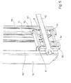
- FIG. 6 an upper part of the door with the drive unit 17 and the drive means 2 becomes visible.
- the drive means 2 is driven in the form of the load shaft 58.
- the load gallery 58 For reasons of clarity, only part of the load gallery 58 has been drawn.
- the clamping device 20 is adjustable via an adjusting means 24 in its position. By means of a deflecting wheel 21, the drive means 2 is thus always kept at tension.
- the drive wheel 19 and a transmission axis 18 8 are driven in this case.
- the tensioning device 20 becomes clear in detail.
- a base bottom 63 are laterally bends 62 of a stamped and bent part visible.
- a link 23 in which a guide element 28 of a two-sided arm 27 engages.
- This arm 27 is mounted in a pivot point 29 so that on the longer arm at the end via an axis 26, the guide wheel 21 is rotatably mounted.
- the other end extending from the pivot point 29 driver 32 acts with a switching element 30, in the form of a switching spring 31, for detecting the proper voltage to the drive means 2, together.
- a spring element 25 is employed against the arm 27 so that a corresponding pressure on the drive means 2 is always maintained by the spring element 25.
- the actuating means 24 On the basic adjustability of the entire clamping device 20 can be influenced by the actuating means 24. So that a sufficient adjustability is given here, located in the drive module according to the FIG. 6 a slot 22.
- FIG. 9 is an exploded view of the FIG. 9 resorted.
- a connecting lever 39 is present. While the Torblattanitati 5 is connected to the driver 1 via the bore 41, at the other end to the connecting lever 39 via preferably executed as a ball joint connection a pivot point 40, which realizes the connection to a transmission lever 44 with the ball joint connection 54.
- the transmission lever 44 is connected and secured within a bore 55 with existing at a bend 47 of the stop plate 36 axis of rotation 42. Through the connection over the Bore 55 thus arises for the transmission lever 44 a two-armed lever, at one end of the connecting lever 39 is fixed and at the other end an adjustment of the connection to the driver 1 has been created.
- the adjustability results from a, guided within a link 45 bush 46 with a threaded bore 54.
- the bushing 46 has lateral surfaces which cooperate within an opening 52 on the stop plate 36 such that the bushing in a bore 56 of a variable slider 48th dips and is pulled over a connecting screw 51 against a guide 49.
- the slider 48 is variable in height.
- the position of the transmission lever 44 is changed at the same time. Due to the adjustability of the adjusting screw 50 thus the point of application for the connecting lever 39 with the driver 1 and the Torblattanitati 5 can be adjusted continuously.
- a link 43 which is aligned with a bore 64 within the guide 49.
- an axle of a roller is introduced, which has not been shown. The role serves to guide the door leaf within the side rail 33rd
Landscapes
- Engineering & Computer Science (AREA)
- Mechanical Engineering (AREA)
- Power-Operated Mechanisms For Wings (AREA)
Applications Claiming Priority (1)
| Application Number | Priority Date | Filing Date | Title |
|---|---|---|---|
| DE102012101415A DE102012101415B3 (de) | 2012-02-22 | 2012-02-22 | Tor |
Publications (3)
| Publication Number | Publication Date |
|---|---|
| EP2631404A2 true EP2631404A2 (fr) | 2013-08-28 |
| EP2631404A3 EP2631404A3 (fr) | 2014-06-18 |
| EP2631404B1 EP2631404B1 (fr) | 2016-11-30 |
Family
ID=47722165
Family Applications (1)
| Application Number | Title | Priority Date | Filing Date |
|---|---|---|---|
| EP13155913.0A Active EP2631404B1 (fr) | 2012-02-22 | 2013-02-20 | Porte |
Country Status (5)
| Country | Link |
|---|---|
| EP (1) | EP2631404B1 (fr) |
| DE (1) | DE102012101415B3 (fr) |
| DK (1) | DK2631404T3 (fr) |
| ES (1) | ES2610218T3 (fr) |
| PL (1) | PL2631404T3 (fr) |
Families Citing this family (4)
| Publication number | Priority date | Publication date | Assignee | Title |
|---|---|---|---|---|
| DE102015100623B3 (de) | 2015-01-16 | 2016-05-12 | Alpha Deuren International Bv | Tor |
| SI3263820T1 (sl) | 2016-06-28 | 2019-02-28 | Gabrijel Rejc | Motorno gnana in navpično premična dvižna vrata |
| EP3263819B1 (fr) | 2016-06-28 | 2018-12-19 | Gabrijel Rejc | Porte mobile verticalement comprenant un vantail de porte |
| DE102016225079A1 (de) | 2016-12-15 | 2018-06-21 | Gabrijel Rejc Gmbh & Co. Kg | Tor mit einer Absturzsicherung |
Citations (4)
| Publication number | Priority date | Publication date | Assignee | Title |
|---|---|---|---|---|
| DE69219654T2 (de) | 1991-03-22 | 1997-12-11 | M & I Door Systems Ltd | Ausgleichvorrichtung für aufrollbare Tore mit variabler Geschwindigkeit |
| DE202007000460U1 (de) | 2007-01-12 | 2007-04-26 | Adolf Seuster Gmbh & Co. Kg | Rolltor |
| DE102009045796A1 (de) | 2009-10-19 | 2011-04-21 | Cardo Door Production Gmbh | Tor mit seitlichem Antrieb |
| DE102009044492A1 (de) | 2009-11-10 | 2011-05-19 | Efaflex Inženiring D. O. O. Ljubljana | Rolltor, insbesondere schnelllaufendes Industrietor |
Family Cites Families (4)
| Publication number | Priority date | Publication date | Assignee | Title |
|---|---|---|---|---|
| US2672582A (en) * | 1952-03-19 | 1954-03-16 | George W Hahn | Operator for overhead doors |
| US3474317A (en) * | 1967-03-07 | 1969-10-21 | Overhead Door Corp | Safety switch cutoff control |
| US3764874A (en) * | 1972-02-07 | 1973-10-09 | Stanley Works | Garage door opener with instant reverse mechanism |
| US20090249695A1 (en) * | 2008-04-04 | 2009-10-08 | Material Sciences Corporation | Damp rail assembly for garage door opening systems |
-
2012
- 2012-02-22 DE DE102012101415A patent/DE102012101415B3/de active Active
-
2013
- 2013-02-20 DK DK13155913.0T patent/DK2631404T3/da active
- 2013-02-20 PL PL13155913T patent/PL2631404T3/pl unknown
- 2013-02-20 EP EP13155913.0A patent/EP2631404B1/fr active Active
- 2013-02-20 ES ES13155913.0T patent/ES2610218T3/es active Active
Patent Citations (4)
| Publication number | Priority date | Publication date | Assignee | Title |
|---|---|---|---|---|
| DE69219654T2 (de) | 1991-03-22 | 1997-12-11 | M & I Door Systems Ltd | Ausgleichvorrichtung für aufrollbare Tore mit variabler Geschwindigkeit |
| DE202007000460U1 (de) | 2007-01-12 | 2007-04-26 | Adolf Seuster Gmbh & Co. Kg | Rolltor |
| DE102009045796A1 (de) | 2009-10-19 | 2011-04-21 | Cardo Door Production Gmbh | Tor mit seitlichem Antrieb |
| DE102009044492A1 (de) | 2009-11-10 | 2011-05-19 | Efaflex Inženiring D. O. O. Ljubljana | Rolltor, insbesondere schnelllaufendes Industrietor |
Also Published As
| Publication number | Publication date |
|---|---|
| ES2610218T3 (es) | 2017-04-26 |
| PL2631404T3 (pl) | 2017-09-29 |
| DE102012101415B3 (de) | 2013-03-14 |
| EP2631404A3 (fr) | 2014-06-18 |
| EP2631404B1 (fr) | 2016-11-30 |
| DK2631404T3 (da) | 2017-03-13 |
Similar Documents
| Publication | Publication Date | Title |
|---|---|---|
| EP3263819B1 (fr) | Porte mobile verticalement comprenant un vantail de porte | |
| DE102005049585B3 (de) | Gewichtsausgleichseinrichtung für ein Hubtor | |
| DE102014220837B3 (de) | Laufwagen zum leichtgängigen Abstellen eines Schiebeflügels von einem festen Rahmen eines Fensters, einer Tür oder dergleichen | |
| DE102007002650A1 (de) | Drehflügelantrieb | |
| EP2631404B1 (fr) | Porte | |
| EP3296501A1 (fr) | Portail doté d'un élément de porte ainsi qu'élément de fermeture inférieur pour un élément de portail doté d'un élément de porte intégré | |
| EP1197627A1 (fr) | Commande pour portes, en particulier portes de garages | |
| DE202012012514U1 (de) | Spiraltor | |
| EP1176280A1 (fr) | Porte, en particulier porte de garage | |
| DE3508175A1 (de) | Garagentor oder hallentor mit feder-hubmechanik | |
| DE202019002390U1 (de) | Antriebsvorrichtung für einen verschiebbaren Flügel als Schiebeflügel oder verschiebbaren Hebe-Schiebeflügel eines Fensters oder einer Tür | |
| DE102005028823A1 (de) | Umklappmechanismus für Türen | |
| WO2006136129A1 (fr) | Mecanisme de commande de porte a chaine pousseuse ou rigide | |
| AT407067B (de) | Antriebseinrichtung für einen schiebeflügel | |
| EP2818618B1 (fr) | Dispositif de régulation de la séquence de fermeture d'une installation de porte rotative à deux battants | |
| DE102013212650C5 (de) | Vorrichtung zur Regelung der Schließfolge einer zweiflügeligen Drehtüranlage | |
| DE102009060144B4 (de) | Vorrichtung zur Betätigung eines Kipptors | |
| DE3519478A1 (de) | Bodentuerschliesser mit eckantrieb | |
| DE2036560A1 (de) | Vorrichtung zum selbsttätigen Offnen und Schließen von Toren, Fenstern, Klappen oddgl | |
| DE102012102026A1 (de) | Gleitschienenanordnung | |
| DE102012213782B4 (de) | Verlagerungsanordnung zur Verlagerung eines Schiebeflügels eines Fensters, einer Tür oder dergleichen relativ zu einer festen Einfassung mit einem flügelseitigen und einem einfassungsseitigen Steuerelement | |
| DE19816562C1 (de) | Torantrieb | |
| DE102015006740B4 (de) | Drehflügeltürantriebsvorrichtung mit Steuerstange | |
| EP2224085B1 (fr) | Entraînement de portail pour un portail | |
| DE10047372C1 (de) | Antrieb für Tore, insbesondere Garagentore |
Legal Events
| Date | Code | Title | Description |
|---|---|---|---|
| PUAI | Public reference made under article 153(3) epc to a published international application that has entered the european phase |
Free format text: ORIGINAL CODE: 0009012 |
|
| AK | Designated contracting states |
Kind code of ref document: A2 Designated state(s): AL AT BE BG CH CY CZ DE DK EE ES FI FR GB GR HR HU IE IS IT LI LT LU LV MC MK MT NL NO PL PT RO RS SE SI SK SM TR |
|
| AX | Request for extension of the european patent |
Extension state: BA ME |
|
| PUAL | Search report despatched |
Free format text: ORIGINAL CODE: 0009013 |
|
| AK | Designated contracting states |
Kind code of ref document: A3 Designated state(s): AL AT BE BG CH CY CZ DE DK EE ES FI FR GB GR HR HU IE IS IT LI LT LU LV MC MK MT NL NO PL PT RO RS SE SI SK SM TR |
|
| AX | Request for extension of the european patent |
Extension state: BA ME |
|
| RIC1 | Information provided on ipc code assigned before grant |
Ipc: E05F 15/16 20060101AFI20140514BHEP |
|
| 17P | Request for examination filed |
Effective date: 20141216 |
|
| RBV | Designated contracting states (corrected) |
Designated state(s): AL AT BE BG CH CY CZ DE DK EE ES FI FR GB GR HR HU IE IS IT LI LT LU LV MC MK MT NL NO PL PT RO RS SE SI SK SM TR |
|
| REG | Reference to a national code |
Ref country code: DE Ref legal event code: R079 Ref document number: 502013005524 Country of ref document: DE Free format text: PREVIOUS MAIN CLASS: E05F0015160000 Ipc: E05F0015684000 |
|
| GRAP | Despatch of communication of intention to grant a patent |
Free format text: ORIGINAL CODE: EPIDOSNIGR1 |
|
| RIC1 | Information provided on ipc code assigned before grant |
Ipc: E05F 15/684 20150101AFI20160720BHEP Ipc: E05F 15/686 20150101ALI20160720BHEP |
|
| INTG | Intention to grant announced |
Effective date: 20160810 |
|
| GRAS | Grant fee paid |
Free format text: ORIGINAL CODE: EPIDOSNIGR3 |
|
| GRAA | (expected) grant |
Free format text: ORIGINAL CODE: 0009210 |
|
| AK | Designated contracting states |
Kind code of ref document: B1 Designated state(s): AL AT BE BG CH CY CZ DE DK EE ES FI FR GB GR HR HU IE IS IT LI LT LU LV MC MK MT NL NO PL PT RO RS SE SI SK SM TR |
|
| REG | Reference to a national code |
Ref country code: CH Ref legal event code: NV Representative=s name: AMMANN PATENTANWAELTE AG BERN, CH Ref country code: CH Ref legal event code: EP Ref country code: GB Ref legal event code: FG4D Free format text: NOT ENGLISH |
|
| REG | Reference to a national code |
Ref country code: AT Ref legal event code: REF Ref document number: 849974 Country of ref document: AT Kind code of ref document: T Effective date: 20161215 |
|
| REG | Reference to a national code |
Ref country code: IE Ref legal event code: FG4D Free format text: LANGUAGE OF EP DOCUMENT: GERMAN |
|
| REG | Reference to a national code |
Ref country code: DE Ref legal event code: R096 Ref document number: 502013005524 Country of ref document: DE |
|
| REG | Reference to a national code |
Ref country code: SE Ref legal event code: TRGR |
|
| REG | Reference to a national code |
Ref country code: FR Ref legal event code: PLFP Year of fee payment: 5 |
|
| PG25 | Lapsed in a contracting state [announced via postgrant information from national office to epo] |
Ref country code: LV Free format text: LAPSE BECAUSE OF FAILURE TO SUBMIT A TRANSLATION OF THE DESCRIPTION OR TO PAY THE FEE WITHIN THE PRESCRIBED TIME-LIMIT Effective date: 20161130 |
|
| REG | Reference to a national code |
Ref country code: NL Ref legal event code: FP |
|
| REG | Reference to a national code |
Ref country code: DK Ref legal event code: T3 Effective date: 20170307 |
|
| REG | Reference to a national code |
Ref country code: LT Ref legal event code: MG4D |
|
| REG | Reference to a national code |
Ref country code: ES Ref legal event code: FG2A Ref document number: 2610218 Country of ref document: ES Kind code of ref document: T3 Effective date: 20170426 |
|
| PG25 | Lapsed in a contracting state [announced via postgrant information from national office to epo] |
Ref country code: NO Free format text: LAPSE BECAUSE OF FAILURE TO SUBMIT A TRANSLATION OF THE DESCRIPTION OR TO PAY THE FEE WITHIN THE PRESCRIBED TIME-LIMIT Effective date: 20170228 Ref country code: LT Free format text: LAPSE BECAUSE OF FAILURE TO SUBMIT A TRANSLATION OF THE DESCRIPTION OR TO PAY THE FEE WITHIN THE PRESCRIBED TIME-LIMIT Effective date: 20161130 Ref country code: GR Free format text: LAPSE BECAUSE OF FAILURE TO SUBMIT A TRANSLATION OF THE DESCRIPTION OR TO PAY THE FEE WITHIN THE PRESCRIBED TIME-LIMIT Effective date: 20170301 |
|
| PGFP | Annual fee paid to national office [announced via postgrant information from national office to epo] |
Ref country code: CH Payment date: 20170217 Year of fee payment: 5 |
|
| PG25 | Lapsed in a contracting state [announced via postgrant information from national office to epo] |
Ref country code: FI Free format text: LAPSE BECAUSE OF FAILURE TO SUBMIT A TRANSLATION OF THE DESCRIPTION OR TO PAY THE FEE WITHIN THE PRESCRIBED TIME-LIMIT Effective date: 20161130 Ref country code: PT Free format text: LAPSE BECAUSE OF FAILURE TO SUBMIT A TRANSLATION OF THE DESCRIPTION OR TO PAY THE FEE WITHIN THE PRESCRIBED TIME-LIMIT Effective date: 20170330 Ref country code: RS Free format text: LAPSE BECAUSE OF FAILURE TO SUBMIT A TRANSLATION OF THE DESCRIPTION OR TO PAY THE FEE WITHIN THE PRESCRIBED TIME-LIMIT Effective date: 20161130 Ref country code: HR Free format text: LAPSE BECAUSE OF FAILURE TO SUBMIT A TRANSLATION OF THE DESCRIPTION OR TO PAY THE FEE WITHIN THE PRESCRIBED TIME-LIMIT Effective date: 20161130 |
|
| PG25 | Lapsed in a contracting state [announced via postgrant information from national office to epo] |
Ref country code: RO Free format text: LAPSE BECAUSE OF FAILURE TO SUBMIT A TRANSLATION OF THE DESCRIPTION OR TO PAY THE FEE WITHIN THE PRESCRIBED TIME-LIMIT Effective date: 20161130 Ref country code: EE Free format text: LAPSE BECAUSE OF FAILURE TO SUBMIT A TRANSLATION OF THE DESCRIPTION OR TO PAY THE FEE WITHIN THE PRESCRIBED TIME-LIMIT Effective date: 20161130 Ref country code: SK Free format text: LAPSE BECAUSE OF FAILURE TO SUBMIT A TRANSLATION OF THE DESCRIPTION OR TO PAY THE FEE WITHIN THE PRESCRIBED TIME-LIMIT Effective date: 20161130 Ref country code: CZ Free format text: LAPSE BECAUSE OF FAILURE TO SUBMIT A TRANSLATION OF THE DESCRIPTION OR TO PAY THE FEE WITHIN THE PRESCRIBED TIME-LIMIT Effective date: 20161130 |
|
| PG25 | Lapsed in a contracting state [announced via postgrant information from national office to epo] |
Ref country code: BG Free format text: LAPSE BECAUSE OF FAILURE TO SUBMIT A TRANSLATION OF THE DESCRIPTION OR TO PAY THE FEE WITHIN THE PRESCRIBED TIME-LIMIT Effective date: 20170228 Ref country code: SM Free format text: LAPSE BECAUSE OF FAILURE TO SUBMIT A TRANSLATION OF THE DESCRIPTION OR TO PAY THE FEE WITHIN THE PRESCRIBED TIME-LIMIT Effective date: 20161130 |
|
| REG | Reference to a national code |
Ref country code: DE Ref legal event code: R097 Ref document number: 502013005524 Country of ref document: DE |
|
| PG25 | Lapsed in a contracting state [announced via postgrant information from national office to epo] |
Ref country code: MC Free format text: LAPSE BECAUSE OF FAILURE TO SUBMIT A TRANSLATION OF THE DESCRIPTION OR TO PAY THE FEE WITHIN THE PRESCRIBED TIME-LIMIT Effective date: 20161130 |
|
| PLBE | No opposition filed within time limit |
Free format text: ORIGINAL CODE: 0009261 |
|
| STAA | Information on the status of an ep patent application or granted ep patent |
Free format text: STATUS: NO OPPOSITION FILED WITHIN TIME LIMIT |
|
| 26N | No opposition filed |
Effective date: 20170831 |
|
| REG | Reference to a national code |
Ref country code: IE Ref legal event code: MM4A |
|
| PG25 | Lapsed in a contracting state [announced via postgrant information from national office to epo] |
Ref country code: SI Free format text: LAPSE BECAUSE OF FAILURE TO SUBMIT A TRANSLATION OF THE DESCRIPTION OR TO PAY THE FEE WITHIN THE PRESCRIBED TIME-LIMIT Effective date: 20161130 |
|
| PG25 | Lapsed in a contracting state [announced via postgrant information from national office to epo] |
Ref country code: LU Free format text: LAPSE BECAUSE OF NON-PAYMENT OF DUE FEES Effective date: 20170220 |
|
| REG | Reference to a national code |
Ref country code: FR Ref legal event code: PLFP Year of fee payment: 6 |
|
| PG25 | Lapsed in a contracting state [announced via postgrant information from national office to epo] |
Ref country code: IE Free format text: LAPSE BECAUSE OF NON-PAYMENT OF DUE FEES Effective date: 20170220 |
|
| REG | Reference to a national code |
Ref country code: CH Ref legal event code: PL |
|
| PG25 | Lapsed in a contracting state [announced via postgrant information from national office to epo] |
Ref country code: MT Free format text: LAPSE BECAUSE OF FAILURE TO SUBMIT A TRANSLATION OF THE DESCRIPTION OR TO PAY THE FEE WITHIN THE PRESCRIBED TIME-LIMIT Effective date: 20161130 |
|
| PG25 | Lapsed in a contracting state [announced via postgrant information from national office to epo] |
Ref country code: LI Free format text: LAPSE BECAUSE OF NON-PAYMENT OF DUE FEES Effective date: 20180228 Ref country code: CH Free format text: LAPSE BECAUSE OF NON-PAYMENT OF DUE FEES Effective date: 20180228 |
|
| REG | Reference to a national code |
Ref country code: AT Ref legal event code: MM01 Ref document number: 849974 Country of ref document: AT Kind code of ref document: T Effective date: 20180220 |
|
| PG25 | Lapsed in a contracting state [announced via postgrant information from national office to epo] |
Ref country code: AT Free format text: LAPSE BECAUSE OF NON-PAYMENT OF DUE FEES Effective date: 20180220 |
|
| PG25 | Lapsed in a contracting state [announced via postgrant information from national office to epo] |
Ref country code: HU Free format text: LAPSE BECAUSE OF FAILURE TO SUBMIT A TRANSLATION OF THE DESCRIPTION OR TO PAY THE FEE WITHIN THE PRESCRIBED TIME-LIMIT; INVALID AB INITIO Effective date: 20130220 |
|
| PG25 | Lapsed in a contracting state [announced via postgrant information from national office to epo] |
Ref country code: CY Free format text: LAPSE BECAUSE OF NON-PAYMENT OF DUE FEES Effective date: 20161130 |
|
| PG25 | Lapsed in a contracting state [announced via postgrant information from national office to epo] |
Ref country code: MK Free format text: LAPSE BECAUSE OF FAILURE TO SUBMIT A TRANSLATION OF THE DESCRIPTION OR TO PAY THE FEE WITHIN THE PRESCRIBED TIME-LIMIT Effective date: 20161130 |
|
| PG25 | Lapsed in a contracting state [announced via postgrant information from national office to epo] |
Ref country code: TR Free format text: LAPSE BECAUSE OF FAILURE TO SUBMIT A TRANSLATION OF THE DESCRIPTION OR TO PAY THE FEE WITHIN THE PRESCRIBED TIME-LIMIT Effective date: 20161130 |
|
| PG25 | Lapsed in a contracting state [announced via postgrant information from national office to epo] |
Ref country code: AL Free format text: LAPSE BECAUSE OF FAILURE TO SUBMIT A TRANSLATION OF THE DESCRIPTION OR TO PAY THE FEE WITHIN THE PRESCRIBED TIME-LIMIT Effective date: 20161130 Ref country code: IS Free format text: LAPSE BECAUSE OF FAILURE TO SUBMIT A TRANSLATION OF THE DESCRIPTION OR TO PAY THE FEE WITHIN THE PRESCRIBED TIME-LIMIT Effective date: 20170330 |
|
| PGFP | Annual fee paid to national office [announced via postgrant information from national office to epo] |
Ref country code: ES Payment date: 20250331 Year of fee payment: 13 |
|
| PGFP | Annual fee paid to national office [announced via postgrant information from national office to epo] |
Ref country code: NL Payment date: 20260218 Year of fee payment: 14 |
|
| PGFP | Annual fee paid to national office [announced via postgrant information from national office to epo] |
Ref country code: SE Payment date: 20260218 Year of fee payment: 14 |
|
| PGFP | Annual fee paid to national office [announced via postgrant information from national office to epo] |
Ref country code: GB Payment date: 20260219 Year of fee payment: 14 |
|
| PGFP | Annual fee paid to national office [announced via postgrant information from national office to epo] |
Ref country code: DK Payment date: 20260220 Year of fee payment: 14 Ref country code: DE Payment date: 20260218 Year of fee payment: 14 |
|
| PGFP | Annual fee paid to national office [announced via postgrant information from national office to epo] |
Ref country code: BE Payment date: 20260218 Year of fee payment: 14 Ref country code: IT Payment date: 20260219 Year of fee payment: 14 |
|
| PGFP | Annual fee paid to national office [announced via postgrant information from national office to epo] |
Ref country code: FR Payment date: 20260218 Year of fee payment: 14 |
|
| PGFP | Annual fee paid to national office [announced via postgrant information from national office to epo] |
Ref country code: PL Payment date: 20260212 Year of fee payment: 14 |