EP2631428A1 - Segment eines Turbinenleitschaufelträgers - Google Patents
Segment eines Turbinenleitschaufelträgers Download PDFInfo
- Publication number
- EP2631428A1 EP2631428A1 EP12156540.2A EP12156540A EP2631428A1 EP 2631428 A1 EP2631428 A1 EP 2631428A1 EP 12156540 A EP12156540 A EP 12156540A EP 2631428 A1 EP2631428 A1 EP 2631428A1
- Authority
- EP
- European Patent Office
- Prior art keywords
- platform
- section
- guiding surface
- main fluid
- fluid flow
- Prior art date
- Legal status (The legal status is an assumption and is not a legal conclusion. Google has not performed a legal analysis and makes no representation as to the accuracy of the status listed.)
- Withdrawn
Links
- 239000012530 fluid Substances 0.000 claims abstract description 96
- 238000013213 extrapolation Methods 0.000 claims abstract description 11
- 239000011248 coating agent Substances 0.000 claims description 14
- 238000000576 coating method Methods 0.000 claims description 14
- 230000008859 change Effects 0.000 claims description 12
- 238000007254 oxidation reaction Methods 0.000 claims description 9
- 230000003647 oxidation Effects 0.000 claims description 8
- 239000012720 thermal barrier coating Substances 0.000 claims description 8
- 238000001816 cooling Methods 0.000 description 33
- 239000007789 gas Substances 0.000 description 16
- 230000000712 assembly Effects 0.000 description 6
- 238000000429 assembly Methods 0.000 description 6
- 238000000926 separation method Methods 0.000 description 6
- 239000000567 combustion gas Substances 0.000 description 4
- 238000002955 isolation Methods 0.000 description 4
- 238000004519 manufacturing process Methods 0.000 description 4
- 239000000463 material Substances 0.000 description 4
- 230000008901 benefit Effects 0.000 description 3
- 238000005266 casting Methods 0.000 description 3
- 230000000694 effects Effects 0.000 description 3
- 238000010438 heat treatment Methods 0.000 description 3
- 238000002156 mixing Methods 0.000 description 3
- 230000004048 modification Effects 0.000 description 3
- 238000012986 modification Methods 0.000 description 3
- 238000011144 upstream manufacturing Methods 0.000 description 3
- 238000002485 combustion reaction Methods 0.000 description 2
- 238000007796 conventional method Methods 0.000 description 2
- 239000012809 cooling fluid Substances 0.000 description 2
- 239000000446 fuel Substances 0.000 description 2
- 238000003754 machining Methods 0.000 description 2
- 238000000034 method Methods 0.000 description 2
- 238000005452 bending Methods 0.000 description 1
- 230000015572 biosynthetic process Effects 0.000 description 1
- 230000015556 catabolic process Effects 0.000 description 1
- 230000001010 compromised effect Effects 0.000 description 1
- 238000006731 degradation reaction Methods 0.000 description 1
- 230000003111 delayed effect Effects 0.000 description 1
- 230000001419 dependent effect Effects 0.000 description 1
- 239000000203 mixture Substances 0.000 description 1
- 230000002035 prolonged effect Effects 0.000 description 1
- 230000001737 promoting effect Effects 0.000 description 1
- 239000011253 protective coating Substances 0.000 description 1
- 230000009467 reduction Effects 0.000 description 1
- 238000004088 simulation Methods 0.000 description 1
- 230000007704 transition Effects 0.000 description 1
Images


Classifications
-
- F—MECHANICAL ENGINEERING; LIGHTING; HEATING; WEAPONS; BLASTING
- F01—MACHINES OR ENGINES IN GENERAL; ENGINE PLANTS IN GENERAL; STEAM ENGINES
- F01D—NON-POSITIVE DISPLACEMENT MACHINES OR ENGINES, e.g. STEAM TURBINES
- F01D5/00—Blades; Blade-carrying members; Heating, heat-insulating, cooling or antivibration means on the blades or the members
- F01D5/12—Blades
- F01D5/14—Form or construction
- F01D5/141—Shape, i.e. outer, aerodynamic form
- F01D5/142—Shape, i.e. outer, aerodynamic form of the blades of successive rotor or stator blade-rows
- F01D5/143—Contour of the outer or inner working fluid flow path wall, i.e. shroud or hub contour
-
- F—MECHANICAL ENGINEERING; LIGHTING; HEATING; WEAPONS; BLASTING
- F01—MACHINES OR ENGINES IN GENERAL; ENGINE PLANTS IN GENERAL; STEAM ENGINES
- F01D—NON-POSITIVE DISPLACEMENT MACHINES OR ENGINES, e.g. STEAM TURBINES
- F01D9/00—Stators
- F01D9/02—Nozzles; Nozzle boxes; Stator blades; Guide conduits, e.g. individual nozzles
- F01D9/04—Nozzles; Nozzle boxes; Stator blades; Guide conduits, e.g. individual nozzles forming ring or sector
- F01D9/041—Nozzles; Nozzle boxes; Stator blades; Guide conduits, e.g. individual nozzles forming ring or sector using blades
-
- F—MECHANICAL ENGINEERING; LIGHTING; HEATING; WEAPONS; BLASTING
- F05—INDEXING SCHEMES RELATING TO ENGINES OR PUMPS IN VARIOUS SUBCLASSES OF CLASSES F01-F04
- F05D—INDEXING SCHEME FOR ASPECTS RELATING TO NON-POSITIVE-DISPLACEMENT MACHINES OR ENGINES, GAS-TURBINES OR JET-PROPULSION PLANTS
- F05D2240/00—Components
- F05D2240/80—Platforms for stationary or moving blades
-
- F—MECHANICAL ENGINEERING; LIGHTING; HEATING; WEAPONS; BLASTING
- F05—INDEXING SCHEMES RELATING TO ENGINES OR PUMPS IN VARIOUS SUBCLASSES OF CLASSES F01-F04
- F05D—INDEXING SCHEME FOR ASPECTS RELATING TO NON-POSITIVE-DISPLACEMENT MACHINES OR ENGINES, GAS-TURBINES OR JET-PROPULSION PLANTS
- F05D2250/00—Geometry
- F05D2250/70—Shape
Definitions
- the present invention relates to a turbine nozzle segment of a turbo-machine, in particular to a stator vane platform, and to a gas turbine comprising such turbine nozzle segment.
- stator vanes or nozzle guide vanes are designed to direct hot combustion gases onto rotor blades resulting in a rotational movement of a rotor to which the rotor blades are connected.
- the turbine section comprises one or more stator vane assemblies and one or more rotor blade assemblies which are arranged in an alternating order.
- the vanes within the same stator vane assembly and the blades within the same rotor blade assembly are usually identical or similar to each other.
- the vanes include an aerofoil portion, a radial inner platform portion and a radial outer platform portion.
- a stator vane assembly can comprise several segments which are put together to form said annular passage, the passage being bordered by the segments of the inner platform and the segments of the outer platform, each platform forming a circumferentially continuous face in the assembled state.
- the platform portions and other parts within the gas turbine engine may be affected by the above mentioned hot fluids.
- a hot gas stream contacting the platform or the vane or blade may lead to an oxidation of the respective material.
- the respective components may be actively cooled, or a thermally protective coating, such as a thermal barrier coating may be applied.
- Methods for cooling the components of the stator vane assembly comprise impingement cooling, in which jets of cooling air are impinging the non-flow path side of the component, e.g. on the side of a platform facing away from the annular passage, or film cooling, by which cooling air is allowed to enter the flow path of the hot fluid through holes in the wall of the respective component, thereby creating a film of cooler air on the surface on the component.
- impingement cooling in which jets of cooling air are impinging the non-flow path side of the component, e.g. on the side of a platform facing away from the annular passage, or film cooling, by which cooling air is allowed to enter the flow path of the hot fluid through holes in the wall of the respective component, thereby creating a film of cooler air on the surface on the component.
- thermal barrier coating is only effective if the non-flow path side of the respective component, i.e. its backside facing away from the annular passage, is actively cooled, e.g. by impingement cooling. Besides negative effects on performance, providing such cooling features may furthermore result in an increased cost of production of the respective gas turbine component.
- a further problem is the presence of regions which are difficult to cool by such conventional methods. These are for example regions in which the flow path velocity of the hot fluid is very high. In such region, film cooling would be rather difficult to introduce, and due to a high heat transport coefficient, substantial mixing losses will be experienced. Also, such regions may be difficult to access by means of impingement cooling, and accordingly, a thermal barrier coating will be rather ineffective. The regions of the component which are difficult to cool are in consequence prone to accelerated detoriation. In particular, oxidation of the material results in a shortened lifetime of the component.
- An embodiment of the invention provides a turbine nozzle segment of a turbo machine comprising a platform, in particular a stator vane platform, for supporting one or more aerofoils.
- the platform comprises a guiding surface for guiding a main fluid flow of the turbo machine, the guiding surface being located on the side of the platform which is to support the one or more aerofoils, and a first and a second section, wherein the second section is a downstream section located downstream of the first section with respect to the main fluid flow.
- the platform further has a trailing edge with respect to the main fluid flow, wherein the trailing edge of the platform is part of the second section.
- the first section of the platform is formed so as to provide guidance of the main fluid flow along a flow path given by the shape of the guiding surface.
- the second section of the platform is formed such that the guiding surface of the second section is at least at the trailing edge spaced apart from an extrapolation of the guiding surface in the first section towards the trailing edge.
- the spacing is in a direction away from the main fluid flow such that in the second section of the platform, the main fluid flow separates from the guiding surface in operation.
- the heat transfer coefficient between the main fluid flow and the guiding surface can be reduced by reducing the flow velocity local to the wall.
- An excessive heating of the region of the platform adjacent to the trailing edge, which is generally difficult to cool, can thus be prevented. Accordingly, oxidation of this region of the platform can be avoided or at least be delayed, thereby prolonging the lifetime of the turbine nozzle segment. Since no additional measures have to be taken, such as providing additional holes or the like in the component, the improved cooling can be implemented cost efficiently. Also, additional cooling air, which could result in a loss of efficiency, is not required.
- the guiding surface in the second section of the platform is shaped such that an area of recirculation of the main fluid flow is formed adjacent to the guiding surface in said second section, wherein the area of recirculation separates the main fluid flow from the guiding surface.
- the local velocity of the fluid flow next to the guiding surface can be reduced significantly in the second section of the platform, resulting in a reduction of the heat transfer coefficient.
- the main fluid flow may thermally insulate the guiding surface in the second section from the main fluid flow.
- the re-circulation may for example occur by a fraction of the main fluid moving in a direction backwards with respect to the main fluid flow.
- a vortex like flow may form adjacent to the guiding surface in the second section in which a fraction of the main fluid circulates.
- the re-circulation may effectively provide a wall of the fluid which reduces the transfer of heat from the main fluid flow to the guiding surface of the platform in the second section.
- the second section of the platform may comprise a discontinuity in the guiding surface or in the curvature of the guiding surface for providing the above mentioned spacing.
- the discontinuity may be sharp enough so as to cause an area of recirculation.
- the discontinuity may for example be a step, a kink, a bend, a sharp corner or the like.
- the amount of cooling that is required to achieve a satisfactory temperature of the platform in operation can be reduced.
- the discontinuity may extend substantially parallel to the trailing edge of the platform. This may be advantageous if the discontinuity comprises a sudden change in curvature such as a kink or a sharp corner, since it can facilitate the manufacturing of the platform.
- the discontinuity may extend substantially perpendicular to the flow path of the main fluid flow (in particular the flow path at the position of the discontinuity). Such configuration may facilitate the generation of an area of recirculation of the main fluid, thereby reducing the heat transfer from the main fluid to the platform.
- the discontinuity may have any angle between the above defined positions, i.e. between being parallel to the trailing and being perpendicular to the flow path of the main fluid flow.
- the configuration may thus be designed in accordance with the requirements of the particular application.
- the discontinuity may extend between the downstream parts of adjacent aerofoils. Between the aerofoils, it may again extend perpendicular to the direction of the main fluid flow, or perpendicular to the trailing edge, or at any angle in between.
- discontinuity of the guiding surface does not need to be continuous in circumferential direction of the platform, it may for example have a saw tooth shape, e.g. when extending perpendicular to the main fluid flow between adjacent aerofoils.
- the second section of the platform may comprise a step in the guiding surface for providing the spacing, the step extending towards the trailing edge.
- Providing a step as a discontinuity in the guiding surface may have the advantage that an area of re-circulation can be generated rather effectively.
- a step may for example be provided by the platform being thicker in the first section and thinner in the second section.
- the second section of the platform may comprise a sharp corner in the guiding surface, wherein downstream the sharp corner, the guiding surface is sloping away from the flow path of the main fluid flow for providing the spacing.
- the change in the guiding surface is less abrupt than when using a step, which may result in a lower aerodynamic resistance, while the sharp corner may still provide for an effective generation of an area of recirculation.
- the second section of the platform may comprise a change in the curvature of the guiding surface with respect to the curvature of the guiding surface in the first section.
- the change in curvature is such that the guiding surface is sloping away from the flow path of the main fluid flow for providing the spacing.
- the platform may comprise a coating on the guiding surface, and the coating may be provided such that the spacing between the extrapolated flow path and the guiding surface at the trailing edge is achieved by a variation of the thickness of the coating in the second section of the platform.
- the coating may for example comprise a step within the second section, it may become thinner towards the trailing edge so as to provide a sharp corner within the second section or so as to change the curvature of the guiding surface within the second section.
- the coating may comprise within the first section a layer of a first thickness, and within the second section a layer of a second, reduced thickness, or a layer of a changing thickness for providing said spacing.
- the spacing may be provided by forming or casting the platform in accordance with any of the above examples in the manufacturing process, or by machining the second section of the platform accordingly.
- the first section and/or the second section of the platform may for example comprise a thermal barrier coating and/or an oxidation coating, such as AL 2 O 3 .
- Such coating may provide thermal isolation, may reduce the oxidation of the platform and may furthermore provide the above mentioned discontinuity or change in curvature of the guiding surface.
- the turbine nozzle segment may comprise further means for cooling.
- the platform may comprise film cooling holes for injecting a film cooling fluid. Impingement cooling may be provided, wherein a surface of the platform located substantially opposite to the guiding surface may be impingement cooled by being subjected to a stream of cooling fluid.
- the platform is an inner platform.
- An inner platform is located radially inwards with respect to the main fluid flow, e.g. in a direction towards a main shaft of the turbo machine.
- the guiding surface is spaced apart from the extrapolation of the flow path over the whole of the second section.
- the second section may for example extend over at least 10 %, preferably at least 15 % of the guiding surface in the direction of the main fluid flow.
- the guiding surface may be a cylindrical or a frusto conical surface, or a segment thereof, having an axial direction.
- the second section may extend over at least 10 %, preferably at least 15 % of the guiding surface in this axial direction.
- the guiding surface may generally extend from a leading edge to the trailing edge of the platform.
- the platform may be an inner stator platform.
- the turbine nozzle segment may comprise an outer stator platform, and the inner and outer stator platforms may define an annular space there between, e.g. a segment of an annulus.
- the annular space provides a flow path for the main fluid flow.
- One or more aerofoils may extend between the inner stator platform and the outer stator platform.
- the aerofoil may be part of a nozzle guide vane comprised in the turbine nozzle segment.
- the main fluid flow is generally substantially perpendicular to a radial direction of the annular space.
- the turbine nozzle segment is a stator vane segment, the stator vane segment comprising at least one aerofoil.
- a further embodiment provides a gas turbine comprising a turbine nozzle segment according to any of the above mentioned embodiments.
- advantages similar to the ones outlined further above can be achieved.
- the cooling of the platform of the turbine nozzle segment and thus the lifetime thereof may be improved.
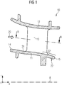
- FIG. 1 shows a sectional side view of a turbine nozzle segment 10 of a type which may be employed with embodiments of the present invention.
- the turbine nozzle segment 10 then comprises an inner platform 11, in particular an inner stator platform, and an outer platform 12. It further comprises an aerofoil 13 which is supported between the inner platform 11 and outer platform 12. Aerofoil 13 may be part of a stator vane, and accordingly, the turbine nozzle segment 10 may be a stator vane segment.
- Inner platform 11 and outer platform 12 are segments of a ring shaped inner and outer assembled platform, respectively, with the centre of such ring being located at the rotational axis (e.g. axis A) of a neighbouring rotor segment. Accordingly, between the inner platform 11 and the outer platform 12, an annular space is formed, through which the aerofoil 13 extends. The annular space provides a flow channel for a main fluid flow 20.
- Main fluid flow 20 generally originates from an upstream combustion chamber, in which fuel for operating the turbo machine is burned.
- Main fluid flow 20 may accordingly comprise a stream of hot combustion gases, and may comprise a mixture of fuel exiting the combustor.
- Turbine nozzle segment 10 is part of a stator vane assembly, having a number of aerofoils 13 distributed circumferentially between the assembled inner and outer platforms.
- One or more such stator vane assemblies may be arranged alternately with rotor blade assemblies in a turbine section of the turbo machine.
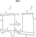
- Rotor blade segment 50 comprises an inner platform 51, and optionally an outer platform 52, with the aerofoil 53 of a rotor blade extending between inner and outer platforms 51 and 52.
- Rotor blade segment 50 forms a rotor blade assembly which extends circumferentially around the axis of rotation of the rotor blade assembly, and includes a plurality of rotor blades distributed in the circumferential direction. Accordingly, by an alternating arrangement of stator vane assemblies and rotor blade assemblies, an annular flow channel is formed for the main fluid flow 20, in particular for hot combustion gases.
- an outer platform 52 is shown in the present example, the rotor blade assembly may be implemented without such platform, wherein for example an inner housing part of a turbine section may provide the annular flow channel.
- Inner platform 11 means that when the turbine nozzle segment 10 is assembled to a stator vane assembly, the platform 11 is located radially inwards, i.e. in the direction of axis A shown in the lower part of figure 1 .
- Outer platform 12 is correspondingly located in radial direction r outwards of inner platform 11.
- the main fluid flow 20 is guided through the annulus formed by inner and outer platforms 11 and 12.
- the fluid washed surface 21 of the inner platform 11 is thus considered to be a guiding surface for the main fluid flow 20.
- the main fluid flow 20 will enter the annulus at the leading edge 14 of the inner platform 11, and will leave the annulus at the trailing edge 15.
- the guiding surface 21 which extends between the leading edge 14 and the trailing edge 15 defines a flow path, with the main fluid flow 20 being essentially parallel to this flow path in proximity to inner platform 11.
- the main fluid flow 20 will be guided by the inner platform 51 of the adjacent rotor blade assembly (see figure 2 ).
- the inner platform 11 comprises a section 32 which is located downstream of the remaining part of inner platform 11 with respect to the main fluid flow 20. While the remaining section of inner platform 11 is considered to be a first section, the downstream section or trailing section 32 is considered to be a second section within the meaning of the application.
- the downstream section 32 of the inner platform 11 may begin at an axial position at which the main part of the aerofoil 13, e.g. more than two thirds (2/3) or more than three quarters (3/4) of the axial extension of the aerofoil 13 are comprised in the first section of platform 11, i.e. located upstream of the downstream section 32.
- Downstream section 32 may accordingly comprise the remaining part of the aerofoil 13, or it may only comprise a section of platform 11 located downstream of the aerofoil 13.
- Guiding surface 21 is facing the main fluid flow 20. Accordingly, when the main fluid flow 20 comprises hot combustion gases, there will be a substantial heat transfer to the guiding surface 21. In particular in the downstream section 32, guiding surface 21 is difficult to cool. Due to the proximity to a neighbouring rotor blade assembly, the non-flow path side of platform 11 in section 32 indicated by reference symbol 22 does not enable an easy access for impingement cooling. Due to the proximity to the stator vanes and the trailing edge 15, film cooling is also difficult to implement.
- Figure 3 is a sectional top view of the turbine nozzle segment 10 of figure 1 taken along the line B-B.
- the inner platform 11 is visible, and the arrangement of the aerofoils 13 can be readily recognized.
- the main fluid flow is again indicated by arrow 20.
- the radial direction now extends perpendicular to the drawing plane, whereas the circumferentially direction C extends in the drawing plane parallel to the trailing edge 15, and the axial direction a extends in the drawing plane perpendicular to the trailing edge 15.
- the first section 31 and the second section 32 of the inner platform 11 are indicated.
- the view is radially inwards, so that guiding surface 21 is now seen from above i.e. from the direction of outer platform 12.
- the shaded area indicates where excessive heating of the inner platform 11 occurs due to the main fluid flow 20.
- the guiding surface 21 can be film cooled, e.g. by injecting cooled gas through holes provided in proximity to the leading edge of the inner platform 11, or can be impingement cooled on the non flowpath side of inner platform 11, such cooling is generally not possible for the shaded areas in the downstream section 32.
- the main fluid flow deviates from the axial direction a.
- a subsequent rotor blade assembly may act on the main fluid flow in the opposite direction, so that an average, the main fluid flow remains essentially parallel to axial direction a.
- embodiments of the invention provide configurations of the inner platform 11 in which the guiding surface 21 is spaced apart from the main fluid flow 20 in the second or downstream section 32.
- the guiding surface 21 in the first section 31 of the inner platform 11 provides guidance along a flow path given by the shape of the guiding surface 21.
- This flow path or in particular the guiding surface within the first section 31 can now be extrapolated into the second section 32 in axial direction a.
- the inner platform 11 is now formed so that the guiding surface is spaced apart from this extrapolation. In particular, it is spaced away from the main fluid flow so that in the second section of platform 11, the main fluid flow 20 separates from the guiding surface 21.
- a discontinuity is provided in the guiding surface 21 or in the curvature of the guiding surface 21 respectively, for achieving the separation of the main fluid flow 20 from the guiding surface 21 in downstream section 32.
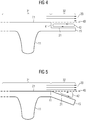
- Figure 4 shows a sectional side view of the downstream portion of the inner platform 11.
- the guiding surface 21 comprises a discontinuity 41 in from of a step within the downstream section 32.
- the guiding surface 21 is accordingly spaced apart from the extrapolation 40 of the guiding surface 21 in the first section 31 towards trailing edge 15.
- a flow separation of the main fluid flow 20 occurs.
- the step extends from the discontinuity 41 to the trailing edge 15.
- a part of the main fluid re-circulates in an area of recirculation 42.
- a fraction of the fluid thus moves backwards with respect to the main fluid flow in an area adjacent to surface 21 in the downstream section 32.
- the recirculation of the main fluid essentially creates an air wall which reduces the transfer of heat from main fluid flow 20 to the guiding surface 21 in the downstream section 32.
- the recirculation reduces the local velocity of the main fluid, and therefore, the heat transfer coefficient is reduced.
- the guiding surface 21 is thus in the downstream section 31 thermally isolated from the high velocity flow of the main fluid.
- the discontinuity 41 is sharp enough so as to ensure that recirculation occurs.
- the modification to the guiding surface 21 is small enough so that additional turbulences and therefore losses in the efficiency of the turbine can be kept small.
- the amount of cooling required for the downstream section 32 is reduced significantly. Accordingly, conventional cooling methods such as impingement cooling, film cooling and a thermal barrier coating are sufficient to reduce the temperature in downstream section 32 to acceptable levels. Accordingly, the lifetime of inner platform 11 can be prolonged.
- the discontinuity 41 may extend substantially parallel to the trailing edge 15, i.e. parallel to the circumferential direction C, see figure 3 .
- the downstream section 32 which comprises the step may start at an axial position which still comprises the downstream parts of aerofoils 13, or it may start in a region located downstream of aerofoils 13.
- the discontinuity may extend substantially parallel to the flow of the main fluid as illustrated in figure 3 .
- the discontinuity may extend parallel to the shading lines of figure 3 , it may for example be located at the first line as seen from the direction of the main fluid flow 20. Accordingly, the discontinuity, e.g. the step or the sharp corner, may not be continuous in circumferential direction C, but it may have a sawtooth shape as in figure 3 or the like.
- the downstream section 32 comprises a discontinuity in the curvature of the guiding surface 21 in form of a sharp corner or bend. Accordingly, the guiding surface 21 is spaced apart from the extrapolation 40 of the guiding surface 21 in the downstream section 32. As can be seen, also in this example, the spacing is provided over the whole downstream section 32, the spacing extending from the discontinuity 41 to the trailing edge 15. Again, an area of recirculation 42 forms adjacent to the guiding surface 21 in the second section 32. Due to the discontinuity 41 in form of a sharp corner, an efficient flow separation of the main fluid flow 20 from the guiding surface 21 can be achieved, so that the generation of an area of recirculation 42 is ensured.
- the additional flow resistance provided by the shape of the guiding surface 21 in the downstream section 32 is kept relatively low since the spacing to the extrapolation line 40 is increased smoothly with distance to the discontinuity 41.
- Figure 6 shows a further embodiment in which the spacing between the extrapolation 40 of guiding surface 21 and the trailing edge 15 is provided by a smooth change in curvature of the guiding surface 21 in the downstream section 32.
- This "curved corner” provides a spacing of the guiding surface 21 to the main fluid flow 20 that is large enough to cause a separation of the main fluid flow 20 from the guiding surface, thereby generating the area of recirculation 42. Due to the smooth change of curvature, the additional flow resistance provided by the shape of the guiding surface 21 in the downstream section 32 can be reduced even further.
- the examples illustrated in figures 4 to 6 are only given for the purpose of illustration, and that other shapes of the guiding surface 21 in the downstream section 32 can be implemented for providing the spacing to the extrapolation 40 of the guiding surface 21 in the first section 31, so that the main fluid flow 20 separates from the guiding surface and the area of recirculation 42 is generated.
- the step of figure 4 may be provided in form of a smooth step having smooth edges, or an additional curvature may be provided further downstream from the step.
- the spacing of the guiding surface 21 to the main fluid flow 20 in the second section 32 is exaggerated for the purpose of illustration.
- the modification in the shape of the guiding surface 21 in downstream section 32 will be kept as small as possible to keep any effects on flow resistance low.
- the dimensions of the step, sharp corner or bending are chosen such that the recirculation takes place and a re-circulating air wall is generated. Suitable dimensions may for example be determined using numerical simulations of the system.
- the required amount of cooling can be reduced significantly for these areas, and accordingly, losses introduced by the cooling can be reduced.
- the guiding surface 21 may be provided both in sections 31 and 32 with a thermal barrier coating and/or with an oxidation coating, such as AL 2 O 3 . Thermal isolation from the main fluid flow and protection against oxidation can thus both be improved.
- Inner platform 11 can be manufactured in different ways for providing the above mentioned spacing.
- One possibility includes providing the discontinuity or the change in curvature by means of a coating, which has a different thickness in the first section 31 and in the second section 32.
- the coating which may for example be the thermal barrier coating, may be applied with different thickness to the first and second sections 31, 32 or it may have a changing thickness within section 32, so as to achieve the spacing as illustrated in any of figures 4 to 6 .
- Other possibilities of providing the spacing in inner platform 11 comprise the machining of the desired shape into the second section 32 of inner platform 11, or casting the inner platform 11 in the desired shape, thus already including the discontinuity or change in curvature within the second section by changing the shape of the base component material.
- recirculation may not develop at all operating points of the turbo machine, e.g. during start up or shut down. It may also depend on the velocity of the main fluid flow 20 and the pressure of the main fluid flow 20.
- the turbine nozzle segment 10 may be manufactured as a single piece, for example by casting, while in other embodiments, aerofoil 13 and platforms 11 and 12 may be separate pieces that are assembled.
- the turbine nozzle segment 10 may define a segment of the annular fluid duct, and two or more segments may be arranged adjacent to each other around the axis A to form the whole annulus.
- the annulus may not be segmented, and the platforms 11 and 12 may have a continuous ring shape around axis A.
- Surface 21 may have a cylindrical or frusto conical shape, yet other shapes, such as slightly curved shapes are also conceivable.
- Turbine nozzle segment 10 can be part of a turbine section of a turbo machine, in particular of a gas turbine.
- the invention may be applied to other types of machines through which a hot fluid is guided.
- machines through which a hot fluid is guided.
- Such include gas turbine engines, compressors, steam turbine engines and the like.
- the invention may be applied to components located in a turbine section and/or within a combustion section.
Landscapes
- Engineering & Computer Science (AREA)
- Mechanical Engineering (AREA)
- General Engineering & Computer Science (AREA)
- Physics & Mathematics (AREA)
- Fluid Mechanics (AREA)
- Turbine Rotor Nozzle Sealing (AREA)
Priority Applications (2)
| Application Number | Priority Date | Filing Date | Title |
|---|---|---|---|
| EP12156540.2A EP2631428A1 (de) | 2012-02-22 | 2012-02-22 | Segment eines Turbinenleitschaufelträgers |
| PCT/EP2013/052588 WO2013124171A1 (en) | 2012-02-22 | 2013-02-08 | Turbine nozzle segment |
Applications Claiming Priority (1)
| Application Number | Priority Date | Filing Date | Title |
|---|---|---|---|
| EP12156540.2A EP2631428A1 (de) | 2012-02-22 | 2012-02-22 | Segment eines Turbinenleitschaufelträgers |
Publications (1)
| Publication Number | Publication Date |
|---|---|
| EP2631428A1 true EP2631428A1 (de) | 2013-08-28 |
Family
ID=47740920
Family Applications (1)
| Application Number | Title | Priority Date | Filing Date |
|---|---|---|---|
| EP12156540.2A Withdrawn EP2631428A1 (de) | 2012-02-22 | 2012-02-22 | Segment eines Turbinenleitschaufelträgers |
Country Status (2)
| Country | Link |
|---|---|
| EP (1) | EP2631428A1 (de) |
| WO (1) | WO2013124171A1 (de) |
Citations (4)
| Publication number | Priority date | Publication date | Assignee | Title |
|---|---|---|---|---|
| GB2042675A (en) * | 1979-02-15 | 1980-09-24 | Rolls Royce | Secondary Flow Control in Axial Fluid Flow Machine |
| FR2624556A1 (fr) * | 1975-05-30 | 1989-06-16 | Rolls Royce Plc | Aubage de distributeur pour moteur a turbine a gaz |
| US20060127214A1 (en) * | 2004-12-10 | 2006-06-15 | David Glasspoole | Gas turbine gas path contour |
| FR2928172A1 (fr) * | 2008-02-28 | 2009-09-04 | Snecma Sa | Aube avec plateforme non axisymetrique lineaire. |
-
2012
- 2012-02-22 EP EP12156540.2A patent/EP2631428A1/de not_active Withdrawn
-
2013
- 2013-02-08 WO PCT/EP2013/052588 patent/WO2013124171A1/en not_active Ceased
Patent Citations (4)
| Publication number | Priority date | Publication date | Assignee | Title |
|---|---|---|---|---|
| FR2624556A1 (fr) * | 1975-05-30 | 1989-06-16 | Rolls Royce Plc | Aubage de distributeur pour moteur a turbine a gaz |
| GB2042675A (en) * | 1979-02-15 | 1980-09-24 | Rolls Royce | Secondary Flow Control in Axial Fluid Flow Machine |
| US20060127214A1 (en) * | 2004-12-10 | 2006-06-15 | David Glasspoole | Gas turbine gas path contour |
| FR2928172A1 (fr) * | 2008-02-28 | 2009-09-04 | Snecma Sa | Aube avec plateforme non axisymetrique lineaire. |
Also Published As
| Publication number | Publication date |
|---|---|
| WO2013124171A1 (en) | 2013-08-29 |
Similar Documents
| Publication | Publication Date | Title |
|---|---|---|
| EP3133254B1 (de) | Kühlkanäle für gasturbinenmotorbauteile | |
| CN101153548B (zh) | 具有增强约束气体流的表面特征的定子-转子组件及工艺 | |
| CN101315032B (zh) | 具有增强的气流封闭表面特征的定子-转子组件和方法 | |
| EP2725201A2 (de) | Axial durchströmte Turbine | |
| EP3121382B1 (de) | Gasturbinenmotoren mit kanalgekühlten haken zum halten eines teils relativ zu einer motorgehäusestruktur | |
| US8801371B2 (en) | Gas turbine | |
| US8408872B2 (en) | Fastback turbulator structure and turbine nozzle incorporating same | |
| US8967973B2 (en) | Turbine bucket platform shaping for gas temperature control and related method | |
| EP2851511A2 (de) | Turbinenschaufeln mit Schaufelspitzenbschnitten mit konvergierenden Kühllöchern | |
| EP3181818B1 (de) | Verfahren zur kühlung | |
| EP3181817B1 (de) | Gasturbinenmotorbauteil mit prallblecheinsatz | |
| CN103075198B (zh) | 涡轮机桨叶平台前缘以及相关方法 | |
| RU2537113C1 (ru) | Газовая турбина, содержащая тепловую защиту, и способ управления | |
| EP2597260B1 (de) | Schaufelanordnung für ein Turbinensystem | |
| CN104564185A (zh) | 用于冷却和/或净化燃气涡轮部段间隙的微通道排气 | |
| US20180230839A1 (en) | Turbine engine shroud assembly | |
| US10337334B2 (en) | Gas turbine engine component with a baffle insert | |
| US10408075B2 (en) | Turbine engine with a rim seal between the rotor and stator | |
| EP3181819B1 (de) | Ablenkplatteneinsatz für eine gasturbinenmotorkomponente | |
| EP2713009B1 (de) | Kühlverfahren und -system zur Kühlung von Schaufeln mindestens einer Schaufelreihe in einer drehenden Strömungsmaschine | |
| JP5770970B2 (ja) | ガスタービンエンジン用タービンノズル | |
| EP2631428A1 (de) | Segment eines Turbinenleitschaufelträgers | |
| GB2473949A (en) | Heat transfer apparatus with turbulators |
Legal Events
| Date | Code | Title | Description |
|---|---|---|---|
| PUAI | Public reference made under article 153(3) epc to a published international application that has entered the european phase |
Free format text: ORIGINAL CODE: 0009012 |
|
| AK | Designated contracting states |
Kind code of ref document: A1 Designated state(s): AL AT BE BG CH CY CZ DE DK EE ES FI FR GB GR HR HU IE IS IT LI LT LU LV MC MK MT NL NO PL PT RO RS SE SI SK SM TR |
|
| AX | Request for extension of the european patent |
Extension state: BA ME |
|
| STAA | Information on the status of an ep patent application or granted ep patent |
Free format text: STATUS: THE APPLICATION IS DEEMED TO BE WITHDRAWN |
|
| 18D | Application deemed to be withdrawn |
Effective date: 20140301 |