EP2631437A2 - Conception de gestion thermique de transducteur de pression de brûleur - Google Patents
Conception de gestion thermique de transducteur de pression de brûleur Download PDFInfo
- Publication number
- EP2631437A2 EP2631437A2 EP13150143.9A EP13150143A EP2631437A2 EP 2631437 A2 EP2631437 A2 EP 2631437A2 EP 13150143 A EP13150143 A EP 13150143A EP 2631437 A2 EP2631437 A2 EP 2631437A2
- Authority
- EP
- European Patent Office
- Prior art keywords
- burner pressure
- heat sink
- water trap
- burner
- chamber
- Prior art date
- Legal status (The legal status is an assumption and is not a legal conclusion. Google has not performed a legal analysis and makes no representation as to the accuracy of the status listed.)
- Granted
Links
Images

Classifications
-
- F—MECHANICAL ENGINEERING; LIGHTING; HEATING; WEAPONS; BLASTING
- F01—MACHINES OR ENGINES IN GENERAL; ENGINE PLANTS IN GENERAL; STEAM ENGINES
- F01D—NON-POSITIVE DISPLACEMENT MACHINES OR ENGINES, e.g. STEAM TURBINES
- F01D25/00—Component parts, details, or accessories, not provided for in, or of interest apart from, other groups
- F01D25/32—Collecting of condensation water; Drainage ; Removing solid particles
-
- F—MECHANICAL ENGINEERING; LIGHTING; HEATING; WEAPONS; BLASTING
- F02—COMBUSTION ENGINES; HOT-GAS OR COMBUSTION-PRODUCT ENGINE PLANTS
- F02C—GAS-TURBINE PLANTS; AIR INTAKES FOR JET-PROPULSION PLANTS; CONTROLLING FUEL SUPPLY IN AIR-BREATHING JET-PROPULSION PLANTS
- F02C7/00—Features, components parts, details or accessories, not provided for in, or of interest apart form groups F02C1/00 - F02C6/00; Air intakes for jet-propulsion plants
-
- F—MECHANICAL ENGINEERING; LIGHTING; HEATING; WEAPONS; BLASTING
- F01—MACHINES OR ENGINES IN GENERAL; ENGINE PLANTS IN GENERAL; STEAM ENGINES
- F01D—NON-POSITIVE DISPLACEMENT MACHINES OR ENGINES, e.g. STEAM TURBINES
- F01D17/00—Regulating or controlling by varying flow
- F01D17/02—Arrangement of sensing elements
- F01D17/08—Arrangement of sensing elements responsive to condition of working-fluid, e.g. pressure
-
- F—MECHANICAL ENGINEERING; LIGHTING; HEATING; WEAPONS; BLASTING
- F02—COMBUSTION ENGINES; HOT-GAS OR COMBUSTION-PRODUCT ENGINE PLANTS
- F02C—GAS-TURBINE PLANTS; AIR INTAKES FOR JET-PROPULSION PLANTS; CONTROLLING FUEL SUPPLY IN AIR-BREATHING JET-PROPULSION PLANTS
- F02C9/00—Controlling gas-turbine plants; Controlling fuel supply in air- breathing jet-propulsion plants
- F02C9/26—Control of fuel supply
- F02C9/28—Regulating systems responsive to plant or ambient parameters, e.g. temperature, pressure, rotor speed
-
- F—MECHANICAL ENGINEERING; LIGHTING; HEATING; WEAPONS; BLASTING
- F05—INDEXING SCHEMES RELATING TO ENGINES OR PUMPS IN VARIOUS SUBCLASSES OF CLASSES F01-F04
- F05D—INDEXING SCHEME FOR ASPECTS RELATING TO NON-POSITIVE-DISPLACEMENT MACHINES OR ENGINES, GAS-TURBINES OR JET-PROPULSION PLANTS
- F05D2270/00—Control
- F05D2270/30—Control parameters, e.g. input parameters
- F05D2270/301—Pressure
-
- F—MECHANICAL ENGINEERING; LIGHTING; HEATING; WEAPONS; BLASTING
- F23—COMBUSTION APPARATUS; COMBUSTION PROCESSES
- F23N—REGULATING OR CONTROLLING COMBUSTION
- F23N2225/00—Measuring
- F23N2225/04—Measuring pressure
Definitions
- the burner pressure sensing line is a pneumatic line that runs from the diffuser case port or burner pressure source to a pressure sensor associated within the electronic engine control housing.
- this pneumatic line is blocked with moisture or ice, the burner pressure signal used to control engine thrust is erroneous. In some cases, this could result in a loss of thrust control which may be a significant safety issue.
- the cause of burner pressure sensing line blockage is the accumulation of moisture in the presence of freezing ambient conditions. This results in blockage of burner pressure passages, preventing the burner pressure from reaching a pressure sensor diaphragm.
- a water trap design is effective in causing moisture to condense and be removed from the air in the sensor line.
- the water trap is placed in an area of the engine that has lower temperatures than the rest of the engine area.
- An inlet is provided to receive burner pressure air from the diffuser case.
- An outlet is provided to send dry air to the pressure sensor in the electronic engine controller.
- the inside of the water trap has a heat sink that promotes condensation of moisture in the air.
- the outside of the water trap may also have a heat sink to further aid condensation.
- system of this invention may have a portion of the burner pressure air line fitted with an external heat sink at a point proximate a hotter part of the engine area, such as proximate an oil tank.
- This heat sink warms the air as it flows to the sensor and maintains any remaining moisture in a gaseous state and prevents condensation.
- the system also employs a deadheaded chamber that provides an alternative location for moisture to accumulate when the moist air in the sense line is compressed during high pressure conditions.
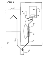
- FIG. 1 is a schematic view of the system of this invention.
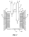
- FIG. 2 is a section view of one element of the system of this invention.
- FIG. 2a is a section view of one element of the system of this invention.
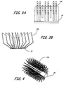
- FIG. 3a and FIG. 3b are details of part of the element in FIG. 2 .
- FIG. 4 is a detail of another element of the system of this invention.
- the water trap device and system 10 includes a source 11 of burner pressure air that passes from source 11 through burner pressure (Bp) sensing line 13 to water trap 15, shown in detail in FIG. 2 , where moisture in the burner pressure air condenses.
- Source 11 is typically a port on the diffuser case.
- the system 10 also includes a deadheaded chamber 40 which provides an alternate location for moist air to condense instead of at the sensor location.
- Water trap 15 is optimally placed in a relatively cool section of the gas turbine engine, which is also the lowest point, typically, in a burner pressure line sensing system. Burner pressure air exits water trap 15 in line 17 and travels to a sensor 18 and deadheaded chamber 40 proximate electronic engine control (EEC) structure 19.
- EEC electronic engine control
- a section 21 of line 17 passes proximate a warmer section of the gas turbine engine, such as proximate oil tank 23 to receive heat and thus add to the condensing function.
- Finned heatsink tube 25, shown in detail in FIG. 4 re-heats the burner pressure gas within line 17 to evaporate any remaining moisture in the burner pressure gas.
- the burner pressure gas enters the conventional pressure sensor 18 within the electronic engine control structure 19. A reliable reading by the sensor 18 is achieved because substantially all the moisture has been removed from the burner pressure gas. Additional element 40 and line 41 are described below.
- FIG. 2 illustrates an enlarged view of water trap 15 which is a chamber having a top 15a, bottom 15b and sides 15c.
- Water trap 15 is shown in section but in use has four sides, herein designated 15c.
- Water trap 15 can be cylindrical, square, rectangular or any shape as long as the sides 15c permit attachment of heat sinks as described below.
- Water trap 15 has an inlet 27 for introducing burner pressure air from source 11 via line 13 of FIG. 1 , such as a diffuser case port. Burner pressure air inside water trap 15 is further cooled by passing over heat sink 29 which is mounted on sides 15c, and which provides lower temperature inside water trap 15. Heat sink 29 may be any effective heat sink. A PIN head heat sink 29 in FIG. 3a takes up less volume than other heat sinks, as pins 29a show, and may be used as shown in FIG. 2 on two sides 15c, or more, of water trap 15.
- a second heat sink 31 is mounted on the outside of water trap 15, also on at least two sides 15c. While any effective heat sink may be used, a flared fin heat sink 31 with flared fins 31a is shown in FIG.3b and it may be used on the outside of water trap 15. Weep hole 37 in bottom 15b provides an outlet for condensed water in water trap 15.
- FIG. 4 illustrates a finned heat sink tube 25 with fins 25a that has been found to be effective.
- the burner pressure gas enters a pressure sensor 18 that is mounted within the engine electronic control structure (EEC) 19.
- EEC engine electronic control structure
- the burner pressure gas from line 17 enters a deadheaded chamber 40 providing an alternative location for the moist air to condense when the gas is compressed at higher pressure. This divides the moist air into two locations greatly reducing the amount of moisture that ends up in the passages leading to the sensor. Any moisture that accumulates or freezes in the deadheaded chamber 40 does not affect the pressure sensor reading.
- FIG. 2a illustrates an enlarged view of deadheaded chamber 40 which is a chamber having a top 40a, bottom 40c and sides 40b.
- Deadheaded chamber 40 is shown in section but in use has four sides, herein designated 40b.
- Deadheaded chamber 40 can be cylindrical, square, rectangular or any shape as long as the sides 40b permit attachment of heat sinks 29 as described below.
- Deadheaded chamber 40 has an inlet 41 for introducing burner pressure air from line 17 of FIG. 1 . Burner pressure air inside deadheaded chamber 40 is further cooled by passing over heat sink 29 which is mounted on sides 40b, and which provides lower temperature inside deadheaded chamber 40. Heat sink 29 may be any effective heat sink. A PIN head heat sink 29 in FIG. 3a has takes up less volume than other heat sinks and may be used as shown in FIG. 2a on two sides 40b, or more, of deadheaded chamber 40.
- the addition of the heats sinks of this invention provides at least three functions. Improved cooling is achieved to condense more water from burner pressure air at water trap 15 as described above. Additional surface area via heat sinks 29 and 33 is provided for condensation to occur.
Landscapes
- Engineering & Computer Science (AREA)
- Mechanical Engineering (AREA)
- General Engineering & Computer Science (AREA)
- Chemical & Material Sciences (AREA)
- Combustion & Propulsion (AREA)
- Measuring Fluid Pressure (AREA)
- Drying Of Gases (AREA)
- Processes For Solid Components From Exhaust (AREA)
Applications Claiming Priority (1)
| Application Number | Priority Date | Filing Date | Title |
|---|---|---|---|
| US13/405,449 US9163527B2 (en) | 2012-02-27 | 2012-02-27 | Burner pressure transducer thermal management design |
Publications (3)
| Publication Number | Publication Date |
|---|---|
| EP2631437A2 true EP2631437A2 (fr) | 2013-08-28 |
| EP2631437A3 EP2631437A3 (fr) | 2016-09-14 |
| EP2631437B1 EP2631437B1 (fr) | 2020-09-23 |
Family
ID=47747325
Family Applications (1)
| Application Number | Title | Priority Date | Filing Date |
|---|---|---|---|
| EP13150143.9A Active EP2631437B1 (fr) | 2012-02-27 | 2013-01-03 | Moteur à turbine à gaz et procédé de fonctionnement |
Country Status (2)
| Country | Link |
|---|---|
| US (1) | US9163527B2 (fr) |
| EP (1) | EP2631437B1 (fr) |
Cited By (4)
| Publication number | Priority date | Publication date | Assignee | Title |
|---|---|---|---|---|
| EP2966412A1 (fr) * | 2014-07-09 | 2016-01-13 | Sick Ag | Capteur avex piège à condensation |
| GB2535623A (en) * | 2015-02-03 | 2016-08-24 | Rolls Royce Plc | Pressure sensing apparatus |
| GB2538383A (en) * | 2015-05-14 | 2016-11-16 | Rolls Royce Plc | A drain for a pressure sensing line |
| US10030536B2 (en) | 2015-02-25 | 2018-07-24 | Rolls-Royce Plc | Icing prevention of a gas turbine engine pressure sensing assembly |
Families Citing this family (3)
| Publication number | Priority date | Publication date | Assignee | Title |
|---|---|---|---|---|
| US10564060B2 (en) | 2018-02-09 | 2020-02-18 | General Electric Company | Pressure sensing devices, systems, and methods for alleviating interference from moisture |
| CN110043374A (zh) * | 2019-05-30 | 2019-07-23 | 广西玉柴机器股份有限公司 | 一种发动机排气背压的控制方法及系统 |
| CN120890601B (zh) * | 2025-09-30 | 2025-12-02 | 厦门纵能电子科技有限公司 | 一种压力仪表高效散热连接器 |
Family Cites Families (14)
| Publication number | Priority date | Publication date | Assignee | Title |
|---|---|---|---|---|
| US4044820A (en) * | 1976-05-24 | 1977-08-30 | Econo-Therm Energy Systems Corporation | Method and apparatus for preheating combustion air while cooling a hot process gas |
| US5499531A (en) * | 1995-03-17 | 1996-03-19 | The Mitre Corporation | System and method for determining volatile constituents, vapor pressure and vapor emissions of liquids |
| JP3561772B2 (ja) * | 1997-12-12 | 2004-09-02 | 株式会社日立製作所 | ガスタービン吸気冷却システム |
| US20030128736A1 (en) * | 2001-11-01 | 2003-07-10 | Dalio Brian A. | Turbine component inspection system |
| US6761031B2 (en) | 2002-09-18 | 2004-07-13 | General Electric Company | Double wall combustor liner segment with enhanced cooling |
| US6892584B2 (en) * | 2002-11-19 | 2005-05-17 | Rosemount Aerospace Inc. | Fabricated pitot probe assembly |
| CA2449538A1 (fr) * | 2003-11-14 | 2005-05-14 | Dynamic Fuel Systems Inc. | Dispositif de production d'oxygene/hydrogene pour moteurs a combustion interne |
| US6971238B1 (en) * | 2004-04-12 | 2005-12-06 | Weldon Eugene Walker | Method for disposal of produced water |
| US7269957B2 (en) | 2004-05-28 | 2007-09-18 | Martling Vincent C | Combustion liner having improved cooling and sealing |
| US7546743B2 (en) | 2005-10-12 | 2009-06-16 | General Electric Company | Bolting configuration for joining ceramic combustor liner to metal mounting attachments |
| US7681403B2 (en) | 2006-04-13 | 2010-03-23 | General Electric Company | Forward sleeve retainer plate and method |
| US8141370B2 (en) | 2006-08-08 | 2012-03-27 | General Electric Company | Methods and apparatus for radially compliant component mounting |
| US8075245B2 (en) * | 2009-05-27 | 2011-12-13 | Dresser-Rand Company | Removal of moisture from process gas |
| US8413494B1 (en) * | 2012-01-19 | 2013-04-09 | Hamilton Sundstrand Corporation | Burner pressure transducer |
-
2012
- 2012-02-27 US US13/405,449 patent/US9163527B2/en active Active
-
2013
- 2013-01-03 EP EP13150143.9A patent/EP2631437B1/fr active Active
Non-Patent Citations (1)
| Title |
|---|
| None |
Cited By (7)
| Publication number | Priority date | Publication date | Assignee | Title |
|---|---|---|---|---|
| EP2966412A1 (fr) * | 2014-07-09 | 2016-01-13 | Sick Ag | Capteur avex piège à condensation |
| GB2535623A (en) * | 2015-02-03 | 2016-08-24 | Rolls Royce Plc | Pressure sensing apparatus |
| US10288527B2 (en) | 2015-02-03 | 2019-05-14 | Rolls-Royce Plc | Pressure sensing apparatus |
| US10030536B2 (en) | 2015-02-25 | 2018-07-24 | Rolls-Royce Plc | Icing prevention of a gas turbine engine pressure sensing assembly |
| GB2538383A (en) * | 2015-05-14 | 2016-11-16 | Rolls Royce Plc | A drain for a pressure sensing line |
| GB2538383B (en) * | 2015-05-14 | 2020-01-22 | Rolls Royce Plc | A drain for a pressure sensing line |
| US10557369B2 (en) | 2015-05-14 | 2020-02-11 | Rolls-Royce Plc | Drain for a pressure sensing line |
Also Published As
| Publication number | Publication date |
|---|---|
| US9163527B2 (en) | 2015-10-20 |
| EP2631437A3 (fr) | 2016-09-14 |
| EP2631437B1 (fr) | 2020-09-23 |
| US20130219902A1 (en) | 2013-08-29 |
Similar Documents
| Publication | Publication Date | Title |
|---|---|---|
| US9163527B2 (en) | Burner pressure transducer thermal management design | |
| JP6295896B2 (ja) | 圧縮空気除湿装置 | |
| JP4920650B2 (ja) | 空気調和機の室外機および空気調和機、並びにその室外機の凍結防止装置 | |
| CN109791026B (zh) | 用于温度调节的存储装置的热虹吸管 | |
| US20140165633A1 (en) | Air compressor | |
| US9989285B2 (en) | Purging apparatus | |
| CN107966041A (zh) | 一种气体除水装置 | |
| CN101358565B (zh) | 排气热回收设备 | |
| US10775083B2 (en) | Purging device, chiller equipped with same, and method for controlling purging device | |
| ITUD990154A1 (it) | Impianto di essicazione per aria compressa | |
| CN109692544B (zh) | 气液分离器及大气采样设备 | |
| JP2009154613A (ja) | 車両の圧縮エア供給装置 | |
| JP6286735B2 (ja) | 圧縮空気除湿装置 | |
| CN106403384A (zh) | 一种采用热气融霜的船用风机蒸发器 | |
| US20240167770A1 (en) | Recuperative temperature regulation for gas dryers in extreme temperature environment | |
| KR20140059215A (ko) | 액체-공기 열 교환 장치를 작동시키기 위한 방법 | |
| KR101558884B1 (ko) | 제습기 | |
| JP5413227B2 (ja) | ヒートポンプ給湯機 | |
| EP2637009A2 (fr) | Capteur et dispositif de chauffage de ligne de détection | |
| US10288527B2 (en) | Pressure sensing apparatus | |
| CN101099378A (zh) | 除湿设备外罩 | |
| ITTV20120006A1 (it) | Dispositivo adatto ad essere inserito in un impianto frigorifero per recuperare il calore di surriscaldamento | |
| KR20090041861A (ko) | 폐수 열회수기가 내설된 응축수 탱크 | |
| JP2008286430A (ja) | 熱交換器 | |
| ITUB20153364A1 (it) | Sistema per lo sbrinamento dell?evaporatore esterno in un impianto a pompa di calore. |
Legal Events
| Date | Code | Title | Description |
|---|---|---|---|
| PUAI | Public reference made under article 153(3) epc to a published international application that has entered the european phase |
Free format text: ORIGINAL CODE: 0009012 |
|
| AK | Designated contracting states |
Kind code of ref document: A2 Designated state(s): AL AT BE BG CH CY CZ DE DK EE ES FI FR GB GR HR HU IE IS IT LI LT LU LV MC MK MT NL NO PL PT RO RS SE SI SK SM TR |
|
| AX | Request for extension of the european patent |
Extension state: BA ME |
|
| PUAL | Search report despatched |
Free format text: ORIGINAL CODE: 0009013 |
|
| AK | Designated contracting states |
Kind code of ref document: A3 Designated state(s): AL AT BE BG CH CY CZ DE DK EE ES FI FR GB GR HR HU IE IS IT LI LT LU LV MC MK MT NL NO PL PT RO RS SE SI SK SM TR |
|
| AX | Request for extension of the european patent |
Extension state: BA ME |
|
| RIC1 | Information provided on ipc code assigned before grant |
Ipc: F01D 25/32 20060101AFI20160811BHEP Ipc: F02C 7/00 20060101ALI20160811BHEP Ipc: G01D 3/036 20060101ALI20160811BHEP Ipc: F01D 17/08 20060101ALI20160811BHEP Ipc: G01D 11/24 20060101ALI20160811BHEP |
|
| STAA | Information on the status of an ep patent application or granted ep patent |
Free format text: STATUS: REQUEST FOR EXAMINATION WAS MADE |
|
| 17P | Request for examination filed |
Effective date: 20170307 |
|
| RBV | Designated contracting states (corrected) |
Designated state(s): AL AT BE BG CH CY CZ DE DK EE ES FI FR GB GR HR HU IE IS IT LI LT LU LV MC MK MT NL NO PL PT RO RS SE SI SK SM TR |
|
| GRAP | Despatch of communication of intention to grant a patent |
Free format text: ORIGINAL CODE: EPIDOSNIGR1 |
|
| STAA | Information on the status of an ep patent application or granted ep patent |
Free format text: STATUS: GRANT OF PATENT IS INTENDED |
|
| INTG | Intention to grant announced |
Effective date: 20200429 |
|
| RIN1 | Information on inventor provided before grant (corrected) |
Inventor name: HARRIS, THOMAS O. |
|
| RAP1 | Party data changed (applicant data changed or rights of an application transferred) |
Owner name: HAMILTON SUNDSTRAND CORPORATION |
|
| GRAS | Grant fee paid |
Free format text: ORIGINAL CODE: EPIDOSNIGR3 |
|
| GRAA | (expected) grant |
Free format text: ORIGINAL CODE: 0009210 |
|
| STAA | Information on the status of an ep patent application or granted ep patent |
Free format text: STATUS: THE PATENT HAS BEEN GRANTED |
|
| AK | Designated contracting states |
Kind code of ref document: B1 Designated state(s): AL AT BE BG CH CY CZ DE DK EE ES FI FR GB GR HR HU IE IS IT LI LT LU LV MC MK MT NL NO PL PT RO RS SE SI SK SM TR |
|
| REG | Reference to a national code |
Ref country code: GB Ref legal event code: FG4D |
|
| REG | Reference to a national code |
Ref country code: CH Ref legal event code: EP |
|
| REG | Reference to a national code |
Ref country code: DE Ref legal event code: R096 Ref document number: 602013072697 Country of ref document: DE |
|
| REG | Reference to a national code |
Ref country code: IE Ref legal event code: FG4D |
|
| REG | Reference to a national code |
Ref country code: AT Ref legal event code: REF Ref document number: 1316571 Country of ref document: AT Kind code of ref document: T Effective date: 20201015 |
|
| PG25 | Lapsed in a contracting state [announced via postgrant information from national office to epo] |
Ref country code: HR Free format text: LAPSE BECAUSE OF FAILURE TO SUBMIT A TRANSLATION OF THE DESCRIPTION OR TO PAY THE FEE WITHIN THE PRESCRIBED TIME-LIMIT Effective date: 20200923 Ref country code: GR Free format text: LAPSE BECAUSE OF FAILURE TO SUBMIT A TRANSLATION OF THE DESCRIPTION OR TO PAY THE FEE WITHIN THE PRESCRIBED TIME-LIMIT Effective date: 20201224 Ref country code: SE Free format text: LAPSE BECAUSE OF FAILURE TO SUBMIT A TRANSLATION OF THE DESCRIPTION OR TO PAY THE FEE WITHIN THE PRESCRIBED TIME-LIMIT Effective date: 20200923 Ref country code: BG Free format text: LAPSE BECAUSE OF FAILURE TO SUBMIT A TRANSLATION OF THE DESCRIPTION OR TO PAY THE FEE WITHIN THE PRESCRIBED TIME-LIMIT Effective date: 20201223 Ref country code: NO Free format text: LAPSE BECAUSE OF FAILURE TO SUBMIT A TRANSLATION OF THE DESCRIPTION OR TO PAY THE FEE WITHIN THE PRESCRIBED TIME-LIMIT Effective date: 20201223 Ref country code: FI Free format text: LAPSE BECAUSE OF FAILURE TO SUBMIT A TRANSLATION OF THE DESCRIPTION OR TO PAY THE FEE WITHIN THE PRESCRIBED TIME-LIMIT Effective date: 20200923 |
|
| REG | Reference to a national code |
Ref country code: AT Ref legal event code: MK05 Ref document number: 1316571 Country of ref document: AT Kind code of ref document: T Effective date: 20200923 |
|
| PG25 | Lapsed in a contracting state [announced via postgrant information from national office to epo] |
Ref country code: RS Free format text: LAPSE BECAUSE OF FAILURE TO SUBMIT A TRANSLATION OF THE DESCRIPTION OR TO PAY THE FEE WITHIN THE PRESCRIBED TIME-LIMIT Effective date: 20200923 Ref country code: LV Free format text: LAPSE BECAUSE OF FAILURE TO SUBMIT A TRANSLATION OF THE DESCRIPTION OR TO PAY THE FEE WITHIN THE PRESCRIBED TIME-LIMIT Effective date: 20200923 |
|
| REG | Reference to a national code |
Ref country code: NL Ref legal event code: MP Effective date: 20200923 |
|
| REG | Reference to a national code |
Ref country code: LT Ref legal event code: MG4D |
|
| PG25 | Lapsed in a contracting state [announced via postgrant information from national office to epo] |
Ref country code: SM Free format text: LAPSE BECAUSE OF FAILURE TO SUBMIT A TRANSLATION OF THE DESCRIPTION OR TO PAY THE FEE WITHIN THE PRESCRIBED TIME-LIMIT Effective date: 20200923 Ref country code: RO Free format text: LAPSE BECAUSE OF FAILURE TO SUBMIT A TRANSLATION OF THE DESCRIPTION OR TO PAY THE FEE WITHIN THE PRESCRIBED TIME-LIMIT Effective date: 20200923 Ref country code: PT Free format text: LAPSE BECAUSE OF FAILURE TO SUBMIT A TRANSLATION OF THE DESCRIPTION OR TO PAY THE FEE WITHIN THE PRESCRIBED TIME-LIMIT Effective date: 20210125 Ref country code: NL Free format text: LAPSE BECAUSE OF FAILURE TO SUBMIT A TRANSLATION OF THE DESCRIPTION OR TO PAY THE FEE WITHIN THE PRESCRIBED TIME-LIMIT Effective date: 20200923 Ref country code: LT Free format text: LAPSE BECAUSE OF FAILURE TO SUBMIT A TRANSLATION OF THE DESCRIPTION OR TO PAY THE FEE WITHIN THE PRESCRIBED TIME-LIMIT Effective date: 20200923 Ref country code: EE Free format text: LAPSE BECAUSE OF FAILURE TO SUBMIT A TRANSLATION OF THE DESCRIPTION OR TO PAY THE FEE WITHIN THE PRESCRIBED TIME-LIMIT Effective date: 20200923 Ref country code: CZ Free format text: LAPSE BECAUSE OF FAILURE TO SUBMIT A TRANSLATION OF THE DESCRIPTION OR TO PAY THE FEE WITHIN THE PRESCRIBED TIME-LIMIT Effective date: 20200923 |
|
| RAP4 | Party data changed (patent owner data changed or rights of a patent transferred) |
Owner name: HAMILTON SUNDSTRAND CORPORATION |
|
| PG25 | Lapsed in a contracting state [announced via postgrant information from national office to epo] |
Ref country code: PL Free format text: LAPSE BECAUSE OF FAILURE TO SUBMIT A TRANSLATION OF THE DESCRIPTION OR TO PAY THE FEE WITHIN THE PRESCRIBED TIME-LIMIT Effective date: 20200923 Ref country code: IS Free format text: LAPSE BECAUSE OF FAILURE TO SUBMIT A TRANSLATION OF THE DESCRIPTION OR TO PAY THE FEE WITHIN THE PRESCRIBED TIME-LIMIT Effective date: 20210123 Ref country code: ES Free format text: LAPSE BECAUSE OF FAILURE TO SUBMIT A TRANSLATION OF THE DESCRIPTION OR TO PAY THE FEE WITHIN THE PRESCRIBED TIME-LIMIT Effective date: 20200923 Ref country code: AL Free format text: LAPSE BECAUSE OF FAILURE TO SUBMIT A TRANSLATION OF THE DESCRIPTION OR TO PAY THE FEE WITHIN THE PRESCRIBED TIME-LIMIT Effective date: 20200923 Ref country code: AT Free format text: LAPSE BECAUSE OF FAILURE TO SUBMIT A TRANSLATION OF THE DESCRIPTION OR TO PAY THE FEE WITHIN THE PRESCRIBED TIME-LIMIT Effective date: 20200923 |
|
| REG | Reference to a national code |
Ref country code: DE Ref legal event code: R097 Ref document number: 602013072697 Country of ref document: DE |
|
| PG25 | Lapsed in a contracting state [announced via postgrant information from national office to epo] |
Ref country code: SK Free format text: LAPSE BECAUSE OF FAILURE TO SUBMIT A TRANSLATION OF THE DESCRIPTION OR TO PAY THE FEE WITHIN THE PRESCRIBED TIME-LIMIT Effective date: 20200923 |
|
| PLBE | No opposition filed within time limit |
Free format text: ORIGINAL CODE: 0009261 |
|
| STAA | Information on the status of an ep patent application or granted ep patent |
Free format text: STATUS: NO OPPOSITION FILED WITHIN TIME LIMIT |
|
| PG25 | Lapsed in a contracting state [announced via postgrant information from national office to epo] |
Ref country code: SI Free format text: LAPSE BECAUSE OF FAILURE TO SUBMIT A TRANSLATION OF THE DESCRIPTION OR TO PAY THE FEE WITHIN THE PRESCRIBED TIME-LIMIT Effective date: 20200923 Ref country code: MC Free format text: LAPSE BECAUSE OF FAILURE TO SUBMIT A TRANSLATION OF THE DESCRIPTION OR TO PAY THE FEE WITHIN THE PRESCRIBED TIME-LIMIT Effective date: 20200923 Ref country code: DK Free format text: LAPSE BECAUSE OF FAILURE TO SUBMIT A TRANSLATION OF THE DESCRIPTION OR TO PAY THE FEE WITHIN THE PRESCRIBED TIME-LIMIT Effective date: 20200923 |
|
| REG | Reference to a national code |
Ref country code: CH Ref legal event code: PL |
|
| 26N | No opposition filed |
Effective date: 20210624 |
|
| PG25 | Lapsed in a contracting state [announced via postgrant information from national office to epo] |
Ref country code: LU Free format text: LAPSE BECAUSE OF NON-PAYMENT OF DUE FEES Effective date: 20210103 |
|
| REG | Reference to a national code |
Ref country code: BE Ref legal event code: MM Effective date: 20210131 |
|
| PG25 | Lapsed in a contracting state [announced via postgrant information from national office to epo] |
Ref country code: IT Free format text: LAPSE BECAUSE OF FAILURE TO SUBMIT A TRANSLATION OF THE DESCRIPTION OR TO PAY THE FEE WITHIN THE PRESCRIBED TIME-LIMIT Effective date: 20200923 |
|
| PG25 | Lapsed in a contracting state [announced via postgrant information from national office to epo] |
Ref country code: CH Free format text: LAPSE BECAUSE OF NON-PAYMENT OF DUE FEES Effective date: 20210131 Ref country code: LI Free format text: LAPSE BECAUSE OF NON-PAYMENT OF DUE FEES Effective date: 20210131 |
|
| PG25 | Lapsed in a contracting state [announced via postgrant information from national office to epo] |
Ref country code: IE Free format text: LAPSE BECAUSE OF NON-PAYMENT OF DUE FEES Effective date: 20210103 |
|
| PG25 | Lapsed in a contracting state [announced via postgrant information from national office to epo] |
Ref country code: BE Free format text: LAPSE BECAUSE OF NON-PAYMENT OF DUE FEES Effective date: 20210131 |
|
| PG25 | Lapsed in a contracting state [announced via postgrant information from national office to epo] |
Ref country code: HU Free format text: LAPSE BECAUSE OF FAILURE TO SUBMIT A TRANSLATION OF THE DESCRIPTION OR TO PAY THE FEE WITHIN THE PRESCRIBED TIME-LIMIT; INVALID AB INITIO Effective date: 20130103 |
|
| P01 | Opt-out of the competence of the unified patent court (upc) registered |
Effective date: 20230522 |
|
| PG25 | Lapsed in a contracting state [announced via postgrant information from national office to epo] |
Ref country code: CY Free format text: LAPSE BECAUSE OF FAILURE TO SUBMIT A TRANSLATION OF THE DESCRIPTION OR TO PAY THE FEE WITHIN THE PRESCRIBED TIME-LIMIT Effective date: 20200923 |
|
| PG25 | Lapsed in a contracting state [announced via postgrant information from national office to epo] |
Ref country code: MK Free format text: LAPSE BECAUSE OF FAILURE TO SUBMIT A TRANSLATION OF THE DESCRIPTION OR TO PAY THE FEE WITHIN THE PRESCRIBED TIME-LIMIT Effective date: 20200923 |
|
| PG25 | Lapsed in a contracting state [announced via postgrant information from national office to epo] |
Ref country code: MT Free format text: LAPSE BECAUSE OF FAILURE TO SUBMIT A TRANSLATION OF THE DESCRIPTION OR TO PAY THE FEE WITHIN THE PRESCRIBED TIME-LIMIT Effective date: 20200923 |
|
| PG25 | Lapsed in a contracting state [announced via postgrant information from national office to epo] |
Ref country code: TR Free format text: LAPSE BECAUSE OF FAILURE TO SUBMIT A TRANSLATION OF THE DESCRIPTION OR TO PAY THE FEE WITHIN THE PRESCRIBED TIME-LIMIT Effective date: 20200923 |
|
| PGFP | Annual fee paid to national office [announced via postgrant information from national office to epo] |
Ref country code: GB Payment date: 20251220 Year of fee payment: 14 |
|
| PGFP | Annual fee paid to national office [announced via postgrant information from national office to epo] |
Ref country code: FR Payment date: 20251217 Year of fee payment: 14 |
|
| PGFP | Annual fee paid to national office [announced via postgrant information from national office to epo] |
Ref country code: DE Payment date: 20251217 Year of fee payment: 14 |