EP2631442A1 - Abgasemissions-steuervorrichtung für einen dieselmotor - Google Patents
Abgasemissions-steuervorrichtung für einen dieselmotor Download PDFInfo
- Publication number
- EP2631442A1 EP2631442A1 EP11834121.3A EP11834121A EP2631442A1 EP 2631442 A1 EP2631442 A1 EP 2631442A1 EP 11834121 A EP11834121 A EP 11834121A EP 2631442 A1 EP2631442 A1 EP 2631442A1
- Authority
- EP
- European Patent Office
- Prior art keywords
- temperature
- dpf
- target
- change rate
- temperature increase
- Prior art date
- Legal status (The legal status is an assumption and is not a legal conclusion. Google has not performed a legal analysis and makes no representation as to the accuracy of the status listed.)
- Granted
Links
Images


Classifications
-
- F—MECHANICAL ENGINEERING; LIGHTING; HEATING; WEAPONS; BLASTING
- F02—COMBUSTION ENGINES; HOT-GAS OR COMBUSTION-PRODUCT ENGINE PLANTS
- F02D—CONTROLLING COMBUSTION ENGINES
- F02D41/00—Electrical control of supply of combustible mixture or its constituents
- F02D41/02—Circuit arrangements for generating control signals
- F02D41/021—Introducing corrections for particular conditions exterior to the engine
- F02D41/0235—Introducing corrections for particular conditions exterior to the engine in relation with the state of the exhaust gas treating apparatus
- F02D41/027—Introducing corrections for particular conditions exterior to the engine in relation with the state of the exhaust gas treating apparatus to purge or regenerate the exhaust gas treating apparatus
- F02D41/029—Introducing corrections for particular conditions exterior to the engine in relation with the state of the exhaust gas treating apparatus to purge or regenerate the exhaust gas treating apparatus the exhaust gas treating apparatus being a particulate filter
-
- B—PERFORMING OPERATIONS; TRANSPORTING
- B01—PHYSICAL OR CHEMICAL PROCESSES OR APPARATUS IN GENERAL
- B01D—SEPARATION
- B01D53/00—Separation of gases or vapours; Recovering vapours of volatile solvents from gases; Chemical or biological purification of waste gases, e.g. engine exhaust gases, smoke, fumes, flue gases, aerosols
- B01D53/34—Chemical or biological purification of waste gases
- B01D53/92—Chemical or biological purification of waste gases of engine exhaust gases
- B01D53/94—Chemical or biological purification of waste gases of engine exhaust gases by catalytic processes
- B01D53/9495—Controlling the catalytic process
-
- F—MECHANICAL ENGINEERING; LIGHTING; HEATING; WEAPONS; BLASTING
- F01—MACHINES OR ENGINES IN GENERAL; ENGINE PLANTS IN GENERAL; STEAM ENGINES
- F01N—GAS-FLOW SILENCERS OR EXHAUST APPARATUS FOR MACHINES OR ENGINES IN GENERAL; GAS-FLOW SILENCERS OR EXHAUST APPARATUS FOR INTERNAL-COMBUSTION ENGINES
- F01N3/00—Exhaust or silencing apparatus having means for purifying, rendering innocuous, or otherwise treating exhaust
- F01N3/08—Exhaust or silencing apparatus having means for purifying, rendering innocuous, or otherwise treating exhaust for rendering innocuous
- F01N3/10—Exhaust or silencing apparatus having means for purifying, rendering innocuous, or otherwise treating exhaust for rendering innocuous by thermal or catalytic conversion of noxious components of exhaust
- F01N3/105—General auxiliary catalysts, e.g. upstream or downstream of the main catalyst
- F01N3/106—Auxiliary oxidation catalysts
-
- F—MECHANICAL ENGINEERING; LIGHTING; HEATING; WEAPONS; BLASTING
- F02—COMBUSTION ENGINES; HOT-GAS OR COMBUSTION-PRODUCT ENGINE PLANTS
- F02D—CONTROLLING COMBUSTION ENGINES
- F02D41/00—Electrical control of supply of combustible mixture or its constituents
- F02D41/02—Circuit arrangements for generating control signals
- F02D41/021—Introducing corrections for particular conditions exterior to the engine
- F02D41/0235—Introducing corrections for particular conditions exterior to the engine in relation with the state of the exhaust gas treating apparatus
-
- F—MECHANICAL ENGINEERING; LIGHTING; HEATING; WEAPONS; BLASTING
- F02—COMBUSTION ENGINES; HOT-GAS OR COMBUSTION-PRODUCT ENGINE PLANTS
- F02D—CONTROLLING COMBUSTION ENGINES
- F02D41/00—Electrical control of supply of combustible mixture or its constituents
- F02D41/02—Circuit arrangements for generating control signals
- F02D41/021—Introducing corrections for particular conditions exterior to the engine
- F02D41/0235—Introducing corrections for particular conditions exterior to the engine in relation with the state of the exhaust gas treating apparatus
- F02D41/024—Introducing corrections for particular conditions exterior to the engine in relation with the state of the exhaust gas treating apparatus to increase temperature of the exhaust gas treating apparatus
- F02D41/025—Introducing corrections for particular conditions exterior to the engine in relation with the state of the exhaust gas treating apparatus to increase temperature of the exhaust gas treating apparatus by changing the composition of the exhaust gas, e.g. for exothermic reaction on exhaust gas treating apparatus
-
- F—MECHANICAL ENGINEERING; LIGHTING; HEATING; WEAPONS; BLASTING
- F02—COMBUSTION ENGINES; HOT-GAS OR COMBUSTION-PRODUCT ENGINE PLANTS
- F02D—CONTROLLING COMBUSTION ENGINES
- F02D41/00—Electrical control of supply of combustible mixture or its constituents
- F02D41/02—Circuit arrangements for generating control signals
- F02D41/14—Introducing closed-loop corrections
- F02D41/1401—Introducing closed-loop corrections characterised by the control or regulation method
-
- F—MECHANICAL ENGINEERING; LIGHTING; HEATING; WEAPONS; BLASTING
- F02—COMBUSTION ENGINES; HOT-GAS OR COMBUSTION-PRODUCT ENGINE PLANTS
- F02D—CONTROLLING COMBUSTION ENGINES
- F02D41/00—Electrical control of supply of combustible mixture or its constituents
- F02D41/02—Circuit arrangements for generating control signals
- F02D41/14—Introducing closed-loop corrections
- F02D41/1438—Introducing closed-loop corrections using means for determining characteristics of the combustion gases; Sensors therefor
- F02D41/1444—Introducing closed-loop corrections using means for determining characteristics of the combustion gases; Sensors therefor characterised by the characteristics of the combustion gases
- F02D41/1446—Introducing closed-loop corrections using means for determining characteristics of the combustion gases; Sensors therefor characterised by the characteristics of the combustion gases the characteristics being exhaust temperatures
-
- F—MECHANICAL ENGINEERING; LIGHTING; HEATING; WEAPONS; BLASTING
- F02—COMBUSTION ENGINES; HOT-GAS OR COMBUSTION-PRODUCT ENGINE PLANTS
- F02D—CONTROLLING COMBUSTION ENGINES
- F02D41/00—Electrical control of supply of combustible mixture or its constituents
- F02D41/30—Controlling fuel injection
- F02D41/38—Controlling fuel injection of the high pressure type
- F02D41/40—Controlling fuel injection of the high pressure type with means for controlling injection timing or duration
- F02D41/402—Multiple injections
- F02D41/405—Multiple injections with post injections
-
- F—MECHANICAL ENGINEERING; LIGHTING; HEATING; WEAPONS; BLASTING
- F01—MACHINES OR ENGINES IN GENERAL; ENGINE PLANTS IN GENERAL; STEAM ENGINES
- F01N—GAS-FLOW SILENCERS OR EXHAUST APPARATUS FOR MACHINES OR ENGINES IN GENERAL; GAS-FLOW SILENCERS OR EXHAUST APPARATUS FOR INTERNAL-COMBUSTION ENGINES
- F01N2900/00—Details of electrical control or of the monitoring of the exhaust gas treating apparatus
- F01N2900/06—Parameters used for exhaust control or diagnosing
- F01N2900/16—Parameters used for exhaust control or diagnosing said parameters being related to the exhaust apparatus, e.g. particulate filter or catalyst
- F01N2900/1602—Temperature of exhaust gas apparatus
-
- F—MECHANICAL ENGINEERING; LIGHTING; HEATING; WEAPONS; BLASTING
- F02—COMBUSTION ENGINES; HOT-GAS OR COMBUSTION-PRODUCT ENGINE PLANTS
- F02D—CONTROLLING COMBUSTION ENGINES
- F02D41/00—Electrical control of supply of combustible mixture or its constituents
- F02D41/02—Circuit arrangements for generating control signals
- F02D41/14—Introducing closed-loop corrections
- F02D41/1401—Introducing closed-loop corrections characterised by the control or regulation method
- F02D2041/1409—Introducing closed-loop corrections characterised by the control or regulation method using at least a proportional, integral or derivative controller
-
- F—MECHANICAL ENGINEERING; LIGHTING; HEATING; WEAPONS; BLASTING
- F02—COMBUSTION ENGINES; HOT-GAS OR COMBUSTION-PRODUCT ENGINE PLANTS
- F02D—CONTROLLING COMBUSTION ENGINES
- F02D41/00—Electrical control of supply of combustible mixture or its constituents
- F02D41/02—Circuit arrangements for generating control signals
- F02D41/14—Introducing closed-loop corrections
- F02D41/1401—Introducing closed-loop corrections characterised by the control or regulation method
- F02D2041/141—Introducing closed-loop corrections characterised by the control or regulation method using a feed-forward control element
-
- F—MECHANICAL ENGINEERING; LIGHTING; HEATING; WEAPONS; BLASTING
- F02—COMBUSTION ENGINES; HOT-GAS OR COMBUSTION-PRODUCT ENGINE PLANTS
- F02D—CONTROLLING COMBUSTION ENGINES
- F02D2200/00—Input parameters for engine control
- F02D2200/02—Input parameters for engine control the parameters being related to the engine
- F02D2200/08—Exhaust gas treatment apparatus parameters
- F02D2200/0802—Temperature of the exhaust gas treatment apparatus
-
- F—MECHANICAL ENGINEERING; LIGHTING; HEATING; WEAPONS; BLASTING
- F02—COMBUSTION ENGINES; HOT-GAS OR COMBUSTION-PRODUCT ENGINE PLANTS
- F02D—CONTROLLING COMBUSTION ENGINES
- F02D2200/00—Input parameters for engine control
- F02D2200/02—Input parameters for engine control the parameters being related to the engine
- F02D2200/10—Parameters related to the engine output, e.g. engine torque or engine speed
- F02D2200/101—Engine speed
-
- F—MECHANICAL ENGINEERING; LIGHTING; HEATING; WEAPONS; BLASTING
- F02—COMBUSTION ENGINES; HOT-GAS OR COMBUSTION-PRODUCT ENGINE PLANTS
- F02D—CONTROLLING COMBUSTION ENGINES
- F02D41/00—Electrical control of supply of combustible mixture or its constituents
- F02D41/02—Circuit arrangements for generating control signals
- F02D41/021—Introducing corrections for particular conditions exterior to the engine
- F02D41/0235—Introducing corrections for particular conditions exterior to the engine in relation with the state of the exhaust gas treating apparatus
- F02D41/024—Introducing corrections for particular conditions exterior to the engine in relation with the state of the exhaust gas treating apparatus to increase temperature of the exhaust gas treating apparatus
- F02D41/0245—Introducing corrections for particular conditions exterior to the engine in relation with the state of the exhaust gas treating apparatus to increase temperature of the exhaust gas treating apparatus by increasing temperature of the exhaust gas leaving the engine
-
- Y—GENERAL TAGGING OF NEW TECHNOLOGICAL DEVELOPMENTS; GENERAL TAGGING OF CROSS-SECTIONAL TECHNOLOGIES SPANNING OVER SEVERAL SECTIONS OF THE IPC; TECHNICAL SUBJECTS COVERED BY FORMER USPC CROSS-REFERENCE ART COLLECTIONS [XRACs] AND DIGESTS
- Y02—TECHNOLOGIES OR APPLICATIONS FOR MITIGATION OR ADAPTATION AGAINST CLIMATE CHANGE
- Y02T—CLIMATE CHANGE MITIGATION TECHNOLOGIES RELATED TO TRANSPORTATION
- Y02T10/00—Road transport of goods or passengers
- Y02T10/10—Internal combustion engine [ICE] based vehicles
- Y02T10/12—Improving ICE efficiencies
-
- Y—GENERAL TAGGING OF NEW TECHNOLOGICAL DEVELOPMENTS; GENERAL TAGGING OF CROSS-SECTIONAL TECHNOLOGIES SPANNING OVER SEVERAL SECTIONS OF THE IPC; TECHNICAL SUBJECTS COVERED BY FORMER USPC CROSS-REFERENCE ART COLLECTIONS [XRACs] AND DIGESTS
- Y02—TECHNOLOGIES OR APPLICATIONS FOR MITIGATION OR ADAPTATION AGAINST CLIMATE CHANGE
- Y02T—CLIMATE CHANGE MITIGATION TECHNOLOGIES RELATED TO TRANSPORTATION
- Y02T10/00—Road transport of goods or passengers
- Y02T10/10—Internal combustion engine [ICE] based vehicles
- Y02T10/40—Engine management systems
Definitions
- the present invention relates to an exhaust emission control device of a diesel engine, and particularly relates to regeneration control of a diesel particulate filter (hereinafter abbreviated as DPF) which collects particulate matter (hereinafter abbreviated as PM) contained in exhaust gas.
- DPF diesel particulate filter
- DPF is a PM collection device which uses a filter. In an engine operation state where an exhaust gas temperature is low, the PM is continuously accumulated in the DPF so that forced regeneration in which a temperature is forcibly increased and the PM is thereby burnt is performed.
- Patent Document 1 discloses that an inlet temperature target value of the DPF is determined based on any of a soot accumulation quantity, a soot accumulation quantity change rate, a DPF temperature, and a DPF temperature change rate.
- Patent Document 2 discloses a technique in which a target DPF inlet temperature is stepwise changed such that the target temperature is increased to the target temperature at the next step when the target DPF inlet temperature is maintained for a predetermined period of time or longer.
- Patent Document 3 discloses that a period of time elapsed since start of the forced regeneration of the DPF is measured, a DPF inlet temperature target value is set to a lower value as the measured period of time is shorter, and a forced regeneration unit sets the injection quantity of sub fuel injection in accordance with the target temperature to perform the sub fuel injection.
- Patent Document 1 Japanese Patent Application Laid-open No. 2007-239740
- Patent Document 2 Japanese Patent No. 3951619
- Patent Document 3 Japanese Patent Application Laid-open No. 2009-138702
- the present invention has been achieved in view of the problems, and an object thereof is to provide an exhaust emission control device of a diesel engine capable of increasing the DPF temperature to reduce the regeneration time period in order to reduce the oil dilution quantity, and reducing the danger of an excessive temperature increase of the DPF in the forced regeneration of the DPF.
- the present invention is an exhaust emission control device of a diesel engine including a diesel oxidation catalyst (DOC) and a diesel particulate filter (DPF) which collects particulate matter (PM) in an exhaust passage and performing regeneration on the PM collected in the DPF
- the exhaust emission control device including a regeneration control unit which increases, when an accumulation quantity of the PM exceeds a predetermined value, a temperature of the DPF to a temperature in a vicinity of a predetermined target set temperature to burn and remove the accumulated PM by controlling a temperature increase unit
- the regeneration control unit including a late post fuel injection control unit which injects fuel into a combustion chamber at a timing when no contribution is made to combustion
- the late post fuel injection control unit including a DPF target temperature setting unit which sets a target value of a DPF temperature including an inlet temperature, an exit temperature, or an internal temperature of the DPF, and a calculation portion which calculates a late post injection quantity command value based on a deviation between the target value of the DPF temperature set by the
- the DPF target temperature setting unit includes the temperature increase rate calculation portion which sets the temperature increase change rate such that, until the target set temperature at which the PM is burnt is reached after the start of the late post injection, the temperature increase change rate is reduced in accordance with the period of time elapsed since the start of the late post injection or the increase in DPF temperature, and the target temperature of the DPF temperature is calculated based on the temperature increase rate from the temperature increase rate calculation portion, when the DPF temperature, e.g., the DPF inlet temperature is low (e.g., about 300°C), the target temperature is quickly increased and, when the DPF inlet temperature is high (e.g., about 570°C), the target temperature is slowly increased.
- the DPF temperature e.g., the DPF inlet temperature is low (e.g., about 300°C)
- the target temperature is quickly increased and, when the DPF inlet temperature is high (e.g., about 570°C)
- the target temperature is slowly increased.
- the target set temperature (610 to 650°C) as the combustion temperature of the DPF, prevent an excessive temperature increase, and reduce an oil dilution quantity while reducing the danger of the excessive temperature increase of the DPF.
- the change rate of the target temperature determined by the temperature increase rate setting portion is determined and the target temperature is determined by using the change rate, and hence it is possible to stably attain the target set temperature and stably perform temperature increase control.
- the temperature increase rate setting portion of the DPF target temperature setting unit may preferably include a first temperature increase rate setting portion which sets the temperature increase change rate of the target temperature such that the temperature increase change rate of the target temperature is stepwise or continuously reduced in accordance with the increase in temperature.
- the stepwise temperature increase change rate in the first temperature increase rate setting portion may preferably include two stages of a first-stage change rate and a second-stage change rate lower than the first-stage change rate
- the target set temperature may preferably correspond to the DPF inlet temperature of 610 to 650°C
- a switching temperature at which the change rate is switched between the first-stage and second-stage change rates may preferably correspond to the DPF inlet temperature of 500 to 600°C.
- the switching temperature of the change rate is set to the DPF inlet temperature of 500 to 600°C
- the target temperature is quickly increased at the first-stage change rate until the DPF inlet temperature reaches the switching temperature
- the target temperature is slowly increased at the second-stage change rate lower than the first-stage change rate when the DPF inlet temperature exceeds the switching temperature. Consequently, it is possible to quickly attain the target set temperature and prevent the excessive temperature increase.
- the temperature increase rate setting portion of the DPF target temperature setting unit may preferably include a second temperature increase rate setting portion which sets the temperature increase change rate of the target temperature such that the temperature increase change rate of the target temperature is stepwise or continuously reduced until the target set temperature is reached in accordance with the period of time elapsed since the start of the late post injection.
- the stepwise temperature increase change rate in the second temperature increase rate setting portion may preferably include two stages of a first-stage change rate and a second-stage change rate lower than the first-stage change rate
- the target set temperature may preferably correspond to the DPF inlet temperature of 610 to 650°C
- switching time when the change rate is switched between the first-stage and second-stage change rates may preferably be set after a lapse of a predetermined period of time after the start of the late post injection.
- the exhaust emission control device of a diesel engine may preferably further include a feed forward control portion which calculates a basic command value of the late post injection quantity command value in accordance with an operation state of the engine, and a feed forward correction unit which corrects the command value from the feed forward control portion in accordance with the calculated target temperature of the DPF temperature.
- the required feed forward quantity i.e., the basic command value is changed. Accordingly, by correcting the basic command value, it is possible to perform the stable late post fuel injection. In particular, it becomes possible to control the late post fuel injection quantity when the target set temperature is approached with high accuracy, and hence it is possible to reduce the danger of the excessive temperature increase of the DPF.
- the temperature increase change rate of the target temperature is set by the temperature increase rate setting portion of the DPF target temperature setting unit such that, until the target set temperature at which the PM is burnt is reached after the start of the late post injection, the temperature increase change rate of the target temperature is reduced in accordance with the increase in temperature or the period of time elapsed since the start of the late post injection, it is possible to quickly attain the target set temperature (610 to 650°C) as the combustion temperature of the DPF, prevent the excessive temperature increase, and reduce the oil dilution quantity while reducing the danger of the excessive temperature increase of the DPF.
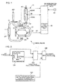
- an exhaust emission control device of a diesel engine in an exhaust passage 3 of a diesel engine (hereinafter referred to as an engine) 1, there is provided an exhaust emission aftertreatment device 11 including DOC 7 and DPF 9 for collecting PM which is disposed on the downstream side of the DOC 7.
- an exhaust turbocharger 17 in the exhaust passage 3, there is provided an exhaust turbocharger 17 having an exhaust turbine 13 and a compressor 15 which is driven coaxially by the exhaust turbine 13. Air discharged from the compressor 15 of the exhaust turbocharger 17 enters into an intercooler 21 through an air supply passage 19 to be cooled, and the flow rate of the air is controlled by an intake throttle valve 23. Thereafter, the air flows into a combustion chamber from an intake manifold 25 through an intake port via an intake valve of the engine 1.
- a fuel injection device (not shown) which controls the injection timing, injection quantity, and injection pressure of fuel to inject the fuel into the combustion chamber is connected to a regeneration control unit (ECU) 29 via a connection terminal 27.
- ECU regeneration control unit
- an EGR (Exhaust Gas Recirculation) passage 33 is branched from some midpoint in the exhaust passage 3 or an exhaust manifold 31, and a part of exhaust gas is sent to the part on the downstream side of the intake throttle valve 23 via an EGR valve 35.
- signals from a DPF inlet temperature sensor 39 and a DPF exit temperature sensor 41 are inputted.
- a fuel injection quantity signal 44 from an engine rotation speed sensor 43 and the fuel injection device is also inputted to the regeneration control unit (ECU) 29.
- ECU regeneration control unit
- the regeneration control unit 29 there are provided a storage portion which stores various map data items and a timer which measures a period of time elapsed since the start of late post fuel injection.
- the regeneration control unit 29 increases the inlet temperature of the DPF 9 to a temperature in the vicinity of a target set temperature (610 to 650°C) to burn and remove the accumulated PM by controlling a temperature increase unit.
- a condition for starting forced regeneration is judged on the basis of, e.g., the running distance, the operation time of an engine, or the total fuel consumption quantity in the case of a vehicle, and the forced regeneration is started, DOC temperature increase control for activating the DOC 7 is executed.
- the quantity of air flowing into the combustion chamber is reduced by reducing the opening of the intake throttle valve 23, and unburned fuel in the exhaust gas is thereby increased.
- the first post injection which injects fuel in a quantity smaller than that in main injection is performed immediately after the main injection in a state where the pressure in the cylinder is still high.
- an exhaust gas temperature is increased without influencing the output of the engine, and the exhaust gas having the increased temperature flows into the DOC 7 to thereby activate the DOC 7.
- the unburned fuel in the exhaust gas is oxidized with the activation of the DOC 7, and the exhaust gas temperature is increased by heat of oxidation generated during the oxidation.
- a DOC inlet temperature reaches a predetermined temperature or the DPF inlet temperature reaches a predetermined temperature and, when the DOC inlet temperature or the DPF inlet temperature exceeds the predetermined temperature, the inlet temperature of the DPF 9 is further increased by late post injection.
- the late post injection mentioned herein denotes the second post injection which injects the fuel in a state where the crank angle is near the bottom dead center after the early post injection.
- the fuel is flown from the combustion chamber to the exhaust passage 3 when the exhaust valve is open, the discharged fuel is caused to react in the already activated DOC 7, the exhaust gas temperature is further increased by the generated heat of oxidation to a temperature required for the regeneration of the DPF 9 such as, e.g., 610 to 650°C, and the burning of the PM is thereby facilitated.
- the regeneration control unit 29 includes a late post fuel injection control unit 50 which injects the fuel at a timing when no contribution is made to combustion in the combustion chamber, and the late post fuel injection control unit 50 includes a feed forward control unit 53 which specifies a basic injection quantity (basic operation quantity) of the late post injection quantity based on a feed forward quantity map (FF map) 51 in which the basic injection quantity is set based on the engine rotation speed and the fuel injection quantity (engine load), and a feed back control unit 55 which specifies a late post correction injection quantity (correction operation quantity) based on a deviation between the target inlet temperature of the DPF 9 and the actual DPF inlet temperature.
- FF map feed forward quantity map
- the feed back control unit 55 includes a DPF target temperature setting unit 52 which sets the target value of the inlet temperature of the DPF, inputs the actual DPF inlet temperature and the target inlet temperature to an adder-subtracter 57 to calculate a deviation therebetween as a control quantity, and performs a feed back calculation on the deviation in a PID calculation portion (calculation portion) 59 to calculate a correction injection quantity as a feed back control command value. Subsequently, the basic injection quantity from the feed forward control unit 53 and the correction injection quantity from the feed back control unit 55 are added together in an adder 61, and outputted as a late post fuel injection quantity command signal.
- the present invention increases the target temperature set by the DPF target temperature setting unit 52 of the feed back control unit 55 to reduce the regeneration time period, allow the regeneration process to be completed in a short time period, and reduce the oil dilution quantity, and sets the target temperature which allows a reduction in the danger of the excessive temperature increase of the DPF.
- the actually measured value of the DPF inlet temperature is inputted from the DPF inlet temperature sensor 39.
- the target change rate (increase rate) of the DPF inlet temperature is calculated by using a first target change rate map (first temperature increase rate setting portion) 101.
- the increase rate is constantly 5°C/sec when the temperature is not mare than 600°C, while the increase rate is 0.5°C/sec when the temperature exceeds 600°C.
- the target temperature calculated at the previous calculation cycle may also be used instead of the actually measured value inputted from the DPF inlet temperature sensor 39. This is because the actually measured value can be considered as a value substantially equal to the value of the target temperature.
- a target value calculation portion 103 the target temperature is calculated based on the actually measured value of the DPF inlet temperature and the calculated target change rate.
- the target temperature is inputted to a selection portion 105, and a signal from a target temperature upper limit value setting portion 107 which sets the upper limit value of the target temperature is also inputted to the selection portion 105.
- the target temperature upper limit value mentioned herein denotes the upper limit value of the target temperature which is set on the basis of the temperature at which catalyst degradation of the DPF 9 occurs.
- the target temperature upper limit value is set to, e.g., 630°C.
- the selection portion 105 the smaller one of the calculated value of the target value calculation portion 103 and the target temperature upper limit value is selected and outputted as the target temperature of the DPF inlet temperature.
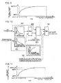
- FIG. 3 shows the state of a change in DPF inlet target temperature.
- a first-stage temperature increase is performed at a constant rate of a first-stage change rate (first-stage temperature increase rate) of 5°C/sec. That is, the temperature increase corresponds to the part of a constant gradient A.
- a second-stage temperature increase is performed at a constant rate of a second-stage change rate (second-stage temperature increase rate) of 0.5°C/sec. That is, the temperature increase corresponds to the part of a constant gradient B.
- the constant gradient temperature increase control is ended and the DPF target temperature setting unit 52 is controlled such that 630°C (610 to 650°C) is maintained.
- a dotted line C indicates, as a conventional art, a case where the DPF inlet target set temperature is constantly 600°C.
- the temperature increase rate of the inlet target temperature of the DPF is changed in two stages.
- the switching temperature of the temperature increase rate of the target temperature is set to 500 to 600°C in the DPF inlet temperature, the target temperature is quickly increased at the first-stage change rate of 5°C/sec until the DPF inlet temperature reaches the switching temperature and, when the DPF temperature exceeds the switching temperature, the target temperature is slowly increased by changing the temperature at the second-stage change rate of 0.5°C/sec which is lower than the first-stage change rate. Consequently, it is possible to quickly attain the target set temperature and prevent the excessive temperature increase.
- the target set temperature (610 to 650°C) is set to a value closest to the upper limit value by setting the target temperature upper limit value such that the target temperature upper limit value corresponds to the inlet temperature target set value T and the target set value is increased, whereby it is possible to allow the regeneration at a high temperature, improve regeneration efficiency, and reduce the oil dilution quantity.
- a second embodiment of the DPF target temperature setting unit 52 is described.
- the temperature increase rate is changed in two stages in the first embodiment, while the second embodiment is characterized in that the temperature increase rate is continuously changed until the target set temperature T is reached.
- the structure of the second embodiment is otherwise the same as that of the first embodiment.
- a second target change rate map (first temperature increase rate setting portion) 201 shown in FIG. 4 is used in the second embodiment.
- the second target change rate map 201 has a feature in which the change rate (increase rate) of the DPF inlet temperature is continuously reduced as the DPF inlet temperature is increased. Consequently, the DPF inlet temperature target value is calculated on the basis of the continuously changing change rate of the target temperature, and hence the inlet temperature target value can be minutely calculated so that it is possible to enhance accuracy in the calculation of the inlet temperature target value.
- FIG. 5 shows the state of a change in DPF inlet target temperature. From the start of the late post injection to the target set temperature T, the DPF inlet target temperature is changed such that the increase rate is continuously reduced as the DPF inlet target temperature is increased.
- a third embodiment of the DPF target temperature setting unit 52 is described.
- the temperature increase rate of the DPF temperature or the DPF target temperature is changed in each of the first and second embodiments, while in the third embodiment, the target change rate is changed in accordance with a period of time elapsed since the start of the late post fuel injection. Consequently, the third embodiment is characterized in that a third target change rate map (second temperature increase rate setting portion) 301 is further provided.
- the target change rate is constantly m1 when the regeneration elapsed time period is not longer than t1 and, when the regeneration elapsed time period is longer than t1, the increase rate is constantly m2.
- the output from the second target change rate map 201 and the output from the third target change rate map 301 are inputted to a selection portion 303, and the smaller one of them is selected and inputted to the target value calculation portion 103.
- a second-stage temperature increase is performed at a constant rate of a second-stage change rate m2. That is, the temperature increase corresponds to the part of a constant gradient B1.
- the constant gradient temperature increase control is ended and the DPF target temperature setting unit 52 is controlled such that 630°C (610 to 650°C) is maintained.
- the time t1 is calculated by a timer incorporated in the regeneration control device 29.
- the temperature increase rate of the inlet target temperature of the DPF 9 is changed in two stages.
- the target temperature is quickly increased at the first-stage change rate m1 and, when the elapsed time period exceeds one minute, the target temperature is slowly increased at the second-stage change rate m2 which is lower than the first-stage change rate. Consequently, it is possible to quickly attain the target set temperature and prevent the excessive temperature increase.
- the switching between the first-stage change rate and the second-stage change rate is set after a lapse of a predetermined period of time after the start of the late post injection, and hence it becomes possible to manage the regeneration behavior of the DPF by using time so that the regeneration behavior can be made constant and stabilized.
- a fourth embodiment of the DPF target temperature setting unit 52 is described.
- the fourth embodiment is characterized in that a fourth target change rate map (second temperature increase rate setting portion) 401 having a feature in which the change rate is continuously changed is provided.
- the fourth target change rate map 401 has a feature in which the change rate (increase rate) of the DPF inlet temperature is continuously reduced with an increase in regeneration elapsed time period. Consequently, the DPF inlet temperature target value is calculated on the basis of the change rate of the target temperature which changes with the increase in regeneration elapsed time period, and hence it is possible to minutely calculate the inlet temperature target value. As a result, it is possible to enhance accuracy in the calculation of the inlet temperature target value. Consequently, even when the target set temperature T is set to a value closest or equal to the target upper limit value, the control of the target temperature is stabilized, and hence it is possible to reliably prevent the excessive temperature increase.
- FIG. 9 shows the state of a change in DPF inlet target temperature. From the start of the late post injection to the target set temperature T, the DPF inlet target temperature is changed such that the increase rate is continuously reduced as the DPF inlet target temperature is increased.
- a fifth embodiment of the DPF target temperature setting unit 52 is described.
- the fifth embodiment is characterized in that a target temperature map 501 in which the target temperature is set based on the period of time elapsed since the start of the late post fuel injection is further provided.
- FIG. 11 shows the state of a change in DPF inlet target temperature. From the start of the late post injection to the target set temperature T, the DPF inlet target temperature is changed such that the increase rate is continuously reduced as the DPF inlet target temperature is increased.
- the regeneration control unit 29 includes the feed forward control portion 53 which calculates the basic command value of the late post injection quantity command value in accordance with the operation state of the engine, and the feed back control unit 55 which specifies the late post correction injection quantity (correction operation quantity) based on the deviation between the target inlet temperature of the DPF 9 and the actual DPF inlet temperature.
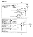
- the target inlet temperature of the feed back control unit 55 is changed, and hence it is necessary to change a feed forward quantity correspondingly to the change. Consequently, the sixth embodiment is characterized in that an FF factor map (feed forward correction unit) 503 which corrects the feed forward quantity is provided.
- the setting of the target temperature in the DPF target temperature setting unit 52 in FIG. 12 is as described in each of the first to fifth embodiments, and the setting of the first embodiment is shown as an example in FIG. 12 .
- the DPF inlet target temperature set value T (°C), the switching temperature (°C), the first-stage increase rate (°C/sec), and the second-stage increase rate (°C/sec) are inputted, and the DPF inlet target temperature is calculated.
- the actually measured DPF inlet temperature and the above-described DPF inlet target temperature are inputted to the adder-subtracter 57, the deviation therebetween is calculated as the control quantity, the deviation is subjected to the feed back calculation in the PID calculation portion 59, and the feed back control command value is calculated and outputted to the adder 61.
- the late post injection quantity for maintaining the switching temperature (e.g., 600°C) is set in the FF (feed forward) quantity map 51.
- FF quantity correction base map 505 a difference between the late post injection quantity for maintaining the DPF inlet temperature target set value T (e.g., 630°C) and the late post injection quantity for maintaining the switching temperature is set.
- the FF quantity factor map 503 there is set a control factor corresponding to the ratio between (the inlet temperature target set value T - the switching temperature) and the inlet target temperature after the switching temperature is reached, i.e., the temperature position of the inlet target temperature between the inlet temperature target set value T and the switching temperature after the switching temperature is reached.
- the target temperature set by the DPF target temperature setting unit 52 is inputted to the adder-subtracter 57, and the control factor corresponding to the target temperature is calculated by using the FF quantity factor map 503. Then, the late post injection quantity to be corrected calculated by the FF quantity correction base map 505 is multiplied by the control factor in a multiplier 507. The correction quantity of the late post injection quantity suitable for the target temperature is calculated in the multiplier 507, the correction quantity is inputted to an adder 509 to be added to the control quantity from the FF quantity map 51, and outputted as a feed forward command value. Subsequently, the feed forward command value is added to the command value from the feed back control unit 55 in the adder 61.
- the correction control in which the control factor corresponding to the target temperature is calculated by using the FF quantity factor map 503 and the multiplication using the control factor is performed in the multiplier 507 is a control operation which is performed only during the second-stage change (the second-stage temperature increase rate). Consequently, the correction is not performed during the first-stage change (the first-stage temperature increase rate). That is, the switching temperature 600°C is already reached in a region during the second-stage change, and hence there is a possibility that an overshoot occurs and the excessive temperature increase is caused depending on the subsequent temperature increase control. Accordingly, it is necessary to determine the late post fuel injection quantity with high accuracy.
- the late post fuel injection quantity is corrected in accordance with the target temperature and the late post fuel injection quantity is stably and reliably controlled.
- the DPF target temperature is changed, by correcting the required feed forward quantity, i.e., the basic command value, it is possible to perform the stable late post fuel injection.
- the regeneration efficiency is enhanced, and the oil dilution quantity is reduced by setting the DPF inlet temperature target set value T (e.g., 630°C) to a temperature higher than about 600°C as the conventional temperature to increase the DPF temperature to a high temperature, it is possible to reduce the danger of the excessive temperature increase of the DPF.
- T e.g., 630°C
- the present invention in forced regeneration of DPF, it is possible to increase a DPF temperature to a high temperature to reduce a recognition time period in order to reduce an oil dilution quantity and also reduce the danger of an excessive temperature increase of the DPF, and hence the present invention is suitably used in an exhaust emission control device of a diesel engine.
Landscapes
- Engineering & Computer Science (AREA)
- Chemical & Material Sciences (AREA)
- Combustion & Propulsion (AREA)
- Mechanical Engineering (AREA)
- General Engineering & Computer Science (AREA)
- Chemical Kinetics & Catalysis (AREA)
- Health & Medical Sciences (AREA)
- Materials Engineering (AREA)
- Analytical Chemistry (AREA)
- General Chemical & Material Sciences (AREA)
- Oil, Petroleum & Natural Gas (AREA)
- Environmental & Geological Engineering (AREA)
- Biomedical Technology (AREA)
- Toxicology (AREA)
- Processes For Solid Components From Exhaust (AREA)
- Filtering Of Dispersed Particles In Gases (AREA)
- Electrical Control Of Air Or Fuel Supplied To Internal-Combustion Engine (AREA)
Applications Claiming Priority (2)
| Application Number | Priority Date | Filing Date | Title |
|---|---|---|---|
| JP2010235966A JP5660847B2 (ja) | 2010-10-20 | 2010-10-20 | ディーゼルエンジンの排気浄化装置 |
| PCT/JP2011/068862 WO2012053279A1 (ja) | 2010-10-20 | 2011-08-22 | ディーゼルエンジンの排気浄化装置 |
Publications (3)
| Publication Number | Publication Date |
|---|---|
| EP2631442A1 true EP2631442A1 (de) | 2013-08-28 |
| EP2631442A4 EP2631442A4 (de) | 2017-12-06 |
| EP2631442B1 EP2631442B1 (de) | 2023-03-01 |
Family
ID=45975002
Family Applications (1)
| Application Number | Title | Priority Date | Filing Date |
|---|---|---|---|
| EP11834121.3A Active EP2631442B1 (de) | 2010-10-20 | 2011-08-22 | Abgasemissions-steuervorrichtung für einen dieselmotor |
Country Status (5)
| Country | Link |
|---|---|
| US (1) | US8893474B2 (de) |
| EP (1) | EP2631442B1 (de) |
| JP (1) | JP5660847B2 (de) |
| CN (1) | CN102959189B (de) |
| WO (1) | WO2012053279A1 (de) |
Families Citing this family (20)
| Publication number | Priority date | Publication date | Assignee | Title |
|---|---|---|---|---|
| US8745967B2 (en) * | 2012-05-04 | 2014-06-10 | GM Global Technology Operations LLC | System and method for controlling exhaust regeneration |
| US9850795B2 (en) * | 2013-04-03 | 2017-12-26 | Volvo Truck Corporation | Method and internal combustion engine arrangement for regenerating an exhaust after-treatment device |
| US9046021B2 (en) * | 2013-06-05 | 2015-06-02 | Tenneco Automotive Operating Company Inc. | Exhaust treatment regeneration control system |
| JP6153793B2 (ja) * | 2013-07-10 | 2017-06-28 | 日野自動車株式会社 | パティキュレートフィルタの再生異常判定装置 |
| US9599005B2 (en) * | 2013-10-01 | 2017-03-21 | Cummins Inc. | Systems and methods for on-board diagnostics of a particulate matter filter |
| KR20150071156A (ko) * | 2013-12-18 | 2015-06-26 | 현대자동차주식회사 | 배기정화장치의 재생 제어방법 및 장치 |
| JP6203658B2 (ja) * | 2014-02-18 | 2017-09-27 | ヤンマー株式会社 | 排気ガス浄化システム |
| JP2015169105A (ja) * | 2014-03-05 | 2015-09-28 | トヨタ自動車株式会社 | 内燃機関の制御装置 |
| US10563549B2 (en) | 2015-09-25 | 2020-02-18 | Eaton Intelligent Power Limited | Cylinder deactivation control and methods |
| CN108431390B (zh) * | 2016-01-19 | 2022-03-18 | 伊顿智能动力有限公司 | 针对热管理的汽缸停用和发动机制动 |
| CN105736091B (zh) * | 2016-03-15 | 2018-06-15 | 清华大学 | 柴油机颗粒捕集器分阶段再生控制方法、装置及系统 |
| CN107654301B (zh) * | 2016-07-25 | 2019-12-24 | 上海汽车集团股份有限公司 | 一种发动机排气歧管的温度控制方法及装置 |
| US10794251B2 (en) | 2016-09-22 | 2020-10-06 | Caterpillar Inc. | Fuel apportionment strategy for in-cylinder dosing |
| JP6349426B2 (ja) * | 2017-03-03 | 2018-06-27 | ルノー・トラックス | 排気後処理装置を再生する方法及び内燃エンジン装置 |
| WO2018200623A1 (en) * | 2017-04-28 | 2018-11-01 | Cummins Inc. | Methods and systems for removing deposits in an aftertreatment system to minimize visible smoke emissions |
| US11131260B2 (en) | 2017-08-14 | 2021-09-28 | Carrier Corporation | Transport refrigeration system and method of regenerating a diesel particulate filter |
| JP7132797B2 (ja) | 2018-08-31 | 2022-09-07 | 三菱重工エンジン&ターボチャージャ株式会社 | Dpf再生制御装置及びdpf再生制御方法 |
| CN113719366B (zh) * | 2021-09-22 | 2022-08-23 | 潍柴动力股份有限公司 | 一种车辆的dpf驻车再生控制方法及装置 |
| CN115075968B (zh) * | 2022-06-13 | 2024-02-20 | 潍柴动力股份有限公司 | 一种发动机dpf再生方法及装置、电子设备 |
| CN118008599B (zh) * | 2024-04-08 | 2024-07-19 | 潍柴动力股份有限公司 | 一种dpf控制方法、装置、系统以及汽车 |
Family Cites Families (21)
| Publication number | Priority date | Publication date | Assignee | Title |
|---|---|---|---|---|
| JP3558017B2 (ja) * | 2000-07-21 | 2004-08-25 | トヨタ自動車株式会社 | 内燃機関の排気浄化装置 |
| JP3951619B2 (ja) | 2001-02-22 | 2007-08-01 | いすゞ自動車株式会社 | 連続再生型ディーゼルパティキュレートフィルタ装置及びその再生制御方法 |
| JP4140371B2 (ja) | 2002-12-16 | 2008-08-27 | 日産自動車株式会社 | パティキュレートフィルタの再生装置及びエンジンの排気ガス浄化装置 |
| JP2004293339A (ja) | 2003-03-25 | 2004-10-21 | Mitsubishi Fuso Truck & Bus Corp | 排ガス浄化装置 |
| JP4367176B2 (ja) * | 2003-05-16 | 2009-11-18 | 株式会社デンソー | 内燃機関の排気浄化装置 |
| JP2005090359A (ja) | 2003-09-17 | 2005-04-07 | Nissan Motor Co Ltd | Dpfの再生制御装置 |
| JP4103813B2 (ja) * | 2004-02-02 | 2008-06-18 | トヨタ自動車株式会社 | 内燃機関の排気浄化装置 |
| WO2006083750A2 (en) * | 2005-01-27 | 2006-08-10 | Southwest Research Institute | Regeneration control for diesel particulate filter for treating diesel engine exhaust |
| JP2006316744A (ja) * | 2005-05-13 | 2006-11-24 | Honda Motor Co Ltd | 内燃機関の排気処理装置 |
| US8261535B2 (en) | 2005-06-30 | 2012-09-11 | GM Global Technology Operations LLC | Enhanced post injection control system for diesel particulate filters |
| WO2007053367A2 (en) * | 2005-10-28 | 2007-05-10 | Corning Incorporated | Regeneration of diesel particulate filters |
| US7677028B2 (en) * | 2006-02-28 | 2010-03-16 | Caterpillar Inc. | Particulate trap regeneration temperature control system |
| DE102006009921B4 (de) | 2006-03-03 | 2022-03-03 | Robert Bosch Gmbh | Verfahren zum Betreiben eines in einem Abgasbereich einer Brennkraftmaschine angeordneten Partikelfilters und Vorrichtung zur Durchführung des Verfahrens |
| JP2007239470A (ja) | 2006-03-06 | 2007-09-20 | Hitachi Ltd | 内燃機関の可変動弁装置 |
| EP1918541B1 (de) * | 2006-11-06 | 2009-02-25 | GM Global Technology Operations, Inc. | Betriebsverfahren für einen Teilchenfilter, Datenverarbeitungsprogramm und Steuerungsvorrichtung dafür |
| JP2009138702A (ja) * | 2007-12-10 | 2009-06-25 | Mitsubishi Fuso Truck & Bus Corp | 排気後処理装置 |
| JP4848406B2 (ja) * | 2008-09-18 | 2011-12-28 | 三菱重工業株式会社 | Dpfの再生制御装置 |
| US8020372B2 (en) | 2008-10-03 | 2011-09-20 | GM Global Technology Operations LLC | Apparatus and method for optimizing exhaust temperature control in a vehicle during particulate filter regneration |
| US8474247B2 (en) * | 2009-03-18 | 2013-07-02 | GM Global Technology Operations LLC | Particulate filter regeneration post-injection fuel rate control |
| US8418441B2 (en) * | 2009-05-29 | 2013-04-16 | Corning Incorporated | Systems and methods for controlling temperature and total hydrocarbon slip |
| JP5404460B2 (ja) * | 2010-02-09 | 2014-01-29 | 三菱重工業株式会社 | エンジンの排気浄化装置及び方法、並びにエンジンの排気浄化装置に係るフィルタの再生システム |
-
2010
- 2010-10-20 JP JP2010235966A patent/JP5660847B2/ja active Active
-
2011
- 2011-08-22 CN CN201180031662.XA patent/CN102959189B/zh active Active
- 2011-08-22 EP EP11834121.3A patent/EP2631442B1/de active Active
- 2011-08-22 US US13/807,191 patent/US8893474B2/en active Active
- 2011-08-22 WO PCT/JP2011/068862 patent/WO2012053279A1/ja not_active Ceased
Non-Patent Citations (1)
| Title |
|---|
| See references of WO2012053279A1 * |
Also Published As
| Publication number | Publication date |
|---|---|
| US20130177482A1 (en) | 2013-07-11 |
| EP2631442B1 (de) | 2023-03-01 |
| CN102959189B (zh) | 2015-08-12 |
| JP2012087705A (ja) | 2012-05-10 |
| EP2631442A4 (de) | 2017-12-06 |
| JP5660847B2 (ja) | 2015-01-28 |
| CN102959189A (zh) | 2013-03-06 |
| US8893474B2 (en) | 2014-11-25 |
| WO2012053279A1 (ja) | 2012-04-26 |
Similar Documents
| Publication | Publication Date | Title |
|---|---|---|
| US8893474B2 (en) | Exhaust emission control device of diesel engine | |
| EP2634409B1 (de) | Abgasreinigungsvorrichtung für einen dieselmotor | |
| CN101302952B (zh) | 排气净化装置 | |
| JP4848406B2 (ja) | Dpfの再生制御装置 | |
| US20060070373A1 (en) | Method for the simultaneous desulfation of a lean NOx trap and regeneration of a diesel particulate filter | |
| US8489308B2 (en) | Method for estimating oxygen concentration downstream a diesel oxidation catalyst | |
| JP5709451B2 (ja) | ディーゼルエンジンの排気浄化装置 | |
| EP1892400A2 (de) | Abgasreinigungssystem eines Verbrennungsmotors und Steuerverfahren des Systems | |
| JP7132798B2 (ja) | Dpf再生制御装置及びdpf再生制御方法 | |
| US9028598B2 (en) | Diesel engine exhaust purification system | |
| JP2006144658A (ja) | 内燃機関の排気浄化装置 | |
| JP7132797B2 (ja) | Dpf再生制御装置及びdpf再生制御方法 | |
| EP2450540A1 (de) | Abgasreinigungsvorrichtung für einen verbrennungsmotor | |
| JP5370252B2 (ja) | 内燃機関の排気浄化装置 | |
| EP3524786B1 (de) | Regenerationssteuerungsvorrichtung für eine abgasreinigungsvorrichtung | |
| EP2216531B1 (de) | Steuerungsverfahren für ein Abgasreinigungssystem und ein Abgasreinigungssystem | |
| JP4857915B2 (ja) | ディーゼルエンジンの制御装置 | |
| JP2010077894A (ja) | Dpf再生制御装置 | |
| EP2581578B1 (de) | Auspuffrohreinspritzsteuerungsvorrichtung | |
| JP4930397B2 (ja) | 内燃機関の排気浄化装置 | |
| JP6198007B2 (ja) | エンジンの制御装置 | |
| EP3988776A1 (de) | Dieselmotor | |
| JP2006266220A (ja) | 後処理装置の昇温制御装置 | |
| JP2010209899A (ja) | ディーゼルエンジンの排気ガス浄化システムおよび排気ガスフィルタの再生方法 |
Legal Events
| Date | Code | Title | Description |
|---|---|---|---|
| PUAI | Public reference made under article 153(3) epc to a published international application that has entered the european phase |
Free format text: ORIGINAL CODE: 0009012 |
|
| 17P | Request for examination filed |
Effective date: 20121217 |
|
| AK | Designated contracting states |
Kind code of ref document: A1 Designated state(s): AL AT BE BG CH CY CZ DE DK EE ES FI FR GB GR HR HU IE IS IT LI LT LU LV MC MK MT NL NO PL PT RO RS SE SI SK SM TR |
|
| DAX | Request for extension of the european patent (deleted) | ||
| RA4 | Supplementary search report drawn up and despatched (corrected) |
Effective date: 20171106 |
|
| RIC1 | Information provided on ipc code assigned before grant |
Ipc: F02D 41/04 20060101ALI20171027BHEP Ipc: F01N 3/02 20060101AFI20171027BHEP Ipc: B01D 46/42 20060101ALI20171027BHEP |
|
| RAP1 | Party data changed (applicant data changed or rights of an application transferred) |
Owner name: MITSUBISHI HEAVY INDUSTRIES ENGINE & TURBOCHARGER, |
|
| STAA | Information on the status of an ep patent application or granted ep patent |
Free format text: STATUS: EXAMINATION IS IN PROGRESS |
|
| 17Q | First examination report despatched |
Effective date: 20180905 |
|
| GRAP | Despatch of communication of intention to grant a patent |
Free format text: ORIGINAL CODE: EPIDOSNIGR1 |
|
| STAA | Information on the status of an ep patent application or granted ep patent |
Free format text: STATUS: GRANT OF PATENT IS INTENDED |
|
| INTG | Intention to grant announced |
Effective date: 20220407 |
|
| GRAJ | Information related to disapproval of communication of intention to grant by the applicant or resumption of examination proceedings by the epo deleted |
Free format text: ORIGINAL CODE: EPIDOSDIGR1 |
|
| STAA | Information on the status of an ep patent application or granted ep patent |
Free format text: STATUS: EXAMINATION IS IN PROGRESS |
|
| GRAP | Despatch of communication of intention to grant a patent |
Free format text: ORIGINAL CODE: EPIDOSNIGR1 |
|
| STAA | Information on the status of an ep patent application or granted ep patent |
Free format text: STATUS: GRANT OF PATENT IS INTENDED |
|
| INTC | Intention to grant announced (deleted) | ||
| INTG | Intention to grant announced |
Effective date: 20220914 |
|
| GRAS | Grant fee paid |
Free format text: ORIGINAL CODE: EPIDOSNIGR3 |
|
| GRAA | (expected) grant |
Free format text: ORIGINAL CODE: 0009210 |
|
| STAA | Information on the status of an ep patent application or granted ep patent |
Free format text: STATUS: THE PATENT HAS BEEN GRANTED |
|
| AK | Designated contracting states |
Kind code of ref document: B1 Designated state(s): AL AT BE BG CH CY CZ DE DK EE ES FI FR GB GR HR HU IE IS IT LI LT LU LV MC MK MT NL NO PL PT RO RS SE SI SK SM TR |
|
| REG | Reference to a national code |
Ref country code: GB Ref legal event code: FG4D |
|
| REG | Reference to a national code |
Ref country code: CH Ref legal event code: EP Ref country code: AT Ref legal event code: REF Ref document number: 1551110 Country of ref document: AT Kind code of ref document: T Effective date: 20230315 |
|
| REG | Reference to a national code |
Ref country code: DE Ref legal event code: R096 Ref document number: 602011073697 Country of ref document: DE |
|
| REG | Reference to a national code |
Ref country code: IE Ref legal event code: FG4D |
|
| REG | Reference to a national code |
Ref country code: LT Ref legal event code: MG9D |
|
| REG | Reference to a national code |
Ref country code: NL Ref legal event code: MP Effective date: 20230301 |
|
| PG25 | Lapsed in a contracting state [announced via postgrant information from national office to epo] |
Ref country code: RS Free format text: LAPSE BECAUSE OF FAILURE TO SUBMIT A TRANSLATION OF THE DESCRIPTION OR TO PAY THE FEE WITHIN THE PRESCRIBED TIME-LIMIT Effective date: 20230301 Ref country code: NO Free format text: LAPSE BECAUSE OF FAILURE TO SUBMIT A TRANSLATION OF THE DESCRIPTION OR TO PAY THE FEE WITHIN THE PRESCRIBED TIME-LIMIT Effective date: 20230601 Ref country code: LV Free format text: LAPSE BECAUSE OF FAILURE TO SUBMIT A TRANSLATION OF THE DESCRIPTION OR TO PAY THE FEE WITHIN THE PRESCRIBED TIME-LIMIT Effective date: 20230301 Ref country code: LT Free format text: LAPSE BECAUSE OF FAILURE TO SUBMIT A TRANSLATION OF THE DESCRIPTION OR TO PAY THE FEE WITHIN THE PRESCRIBED TIME-LIMIT Effective date: 20230301 Ref country code: HR Free format text: LAPSE BECAUSE OF FAILURE TO SUBMIT A TRANSLATION OF THE DESCRIPTION OR TO PAY THE FEE WITHIN THE PRESCRIBED TIME-LIMIT Effective date: 20230301 Ref country code: ES Free format text: LAPSE BECAUSE OF FAILURE TO SUBMIT A TRANSLATION OF THE DESCRIPTION OR TO PAY THE FEE WITHIN THE PRESCRIBED TIME-LIMIT Effective date: 20230301 |
|
| REG | Reference to a national code |
Ref country code: AT Ref legal event code: MK05 Ref document number: 1551110 Country of ref document: AT Kind code of ref document: T Effective date: 20230301 |
|
| PG25 | Lapsed in a contracting state [announced via postgrant information from national office to epo] |
Ref country code: SE Free format text: LAPSE BECAUSE OF FAILURE TO SUBMIT A TRANSLATION OF THE DESCRIPTION OR TO PAY THE FEE WITHIN THE PRESCRIBED TIME-LIMIT Effective date: 20230301 Ref country code: PL Free format text: LAPSE BECAUSE OF FAILURE TO SUBMIT A TRANSLATION OF THE DESCRIPTION OR TO PAY THE FEE WITHIN THE PRESCRIBED TIME-LIMIT Effective date: 20230301 Ref country code: NL Free format text: LAPSE BECAUSE OF FAILURE TO SUBMIT A TRANSLATION OF THE DESCRIPTION OR TO PAY THE FEE WITHIN THE PRESCRIBED TIME-LIMIT Effective date: 20230301 Ref country code: GR Free format text: LAPSE BECAUSE OF FAILURE TO SUBMIT A TRANSLATION OF THE DESCRIPTION OR TO PAY THE FEE WITHIN THE PRESCRIBED TIME-LIMIT Effective date: 20230602 Ref country code: FI Free format text: LAPSE BECAUSE OF FAILURE TO SUBMIT A TRANSLATION OF THE DESCRIPTION OR TO PAY THE FEE WITHIN THE PRESCRIBED TIME-LIMIT Effective date: 20230301 |
|
| PG25 | Lapsed in a contracting state [announced via postgrant information from national office to epo] |
Ref country code: SM Free format text: LAPSE BECAUSE OF FAILURE TO SUBMIT A TRANSLATION OF THE DESCRIPTION OR TO PAY THE FEE WITHIN THE PRESCRIBED TIME-LIMIT Effective date: 20230301 Ref country code: RO Free format text: LAPSE BECAUSE OF FAILURE TO SUBMIT A TRANSLATION OF THE DESCRIPTION OR TO PAY THE FEE WITHIN THE PRESCRIBED TIME-LIMIT Effective date: 20230301 Ref country code: PT Free format text: LAPSE BECAUSE OF FAILURE TO SUBMIT A TRANSLATION OF THE DESCRIPTION OR TO PAY THE FEE WITHIN THE PRESCRIBED TIME-LIMIT Effective date: 20230703 Ref country code: EE Free format text: LAPSE BECAUSE OF FAILURE TO SUBMIT A TRANSLATION OF THE DESCRIPTION OR TO PAY THE FEE WITHIN THE PRESCRIBED TIME-LIMIT Effective date: 20230301 Ref country code: CZ Free format text: LAPSE BECAUSE OF FAILURE TO SUBMIT A TRANSLATION OF THE DESCRIPTION OR TO PAY THE FEE WITHIN THE PRESCRIBED TIME-LIMIT Effective date: 20230301 Ref country code: AT Free format text: LAPSE BECAUSE OF FAILURE TO SUBMIT A TRANSLATION OF THE DESCRIPTION OR TO PAY THE FEE WITHIN THE PRESCRIBED TIME-LIMIT Effective date: 20230301 |
|
| PG25 | Lapsed in a contracting state [announced via postgrant information from national office to epo] |
Ref country code: SK Free format text: LAPSE BECAUSE OF FAILURE TO SUBMIT A TRANSLATION OF THE DESCRIPTION OR TO PAY THE FEE WITHIN THE PRESCRIBED TIME-LIMIT Effective date: 20230301 Ref country code: IS Free format text: LAPSE BECAUSE OF FAILURE TO SUBMIT A TRANSLATION OF THE DESCRIPTION OR TO PAY THE FEE WITHIN THE PRESCRIBED TIME-LIMIT Effective date: 20230701 |
|
| REG | Reference to a national code |
Ref country code: DE Ref legal event code: R097 Ref document number: 602011073697 Country of ref document: DE |
|
| PLBE | No opposition filed within time limit |
Free format text: ORIGINAL CODE: 0009261 |
|
| STAA | Information on the status of an ep patent application or granted ep patent |
Free format text: STATUS: NO OPPOSITION FILED WITHIN TIME LIMIT |
|
| PG25 | Lapsed in a contracting state [announced via postgrant information from national office to epo] |
Ref country code: SI Free format text: LAPSE BECAUSE OF FAILURE TO SUBMIT A TRANSLATION OF THE DESCRIPTION OR TO PAY THE FEE WITHIN THE PRESCRIBED TIME-LIMIT Effective date: 20230301 Ref country code: DK Free format text: LAPSE BECAUSE OF FAILURE TO SUBMIT A TRANSLATION OF THE DESCRIPTION OR TO PAY THE FEE WITHIN THE PRESCRIBED TIME-LIMIT Effective date: 20230301 |
|
| 26N | No opposition filed |
Effective date: 20231204 |
|
| PG25 | Lapsed in a contracting state [announced via postgrant information from national office to epo] |
Ref country code: MC Free format text: LAPSE BECAUSE OF FAILURE TO SUBMIT A TRANSLATION OF THE DESCRIPTION OR TO PAY THE FEE WITHIN THE PRESCRIBED TIME-LIMIT Effective date: 20230301 |
|
| REG | Reference to a national code |
Ref country code: CH Ref legal event code: PL |
|
| PG25 | Lapsed in a contracting state [announced via postgrant information from national office to epo] |
Ref country code: MC Free format text: LAPSE BECAUSE OF FAILURE TO SUBMIT A TRANSLATION OF THE DESCRIPTION OR TO PAY THE FEE WITHIN THE PRESCRIBED TIME-LIMIT Effective date: 20230301 |
|
| PG25 | Lapsed in a contracting state [announced via postgrant information from national office to epo] |
Ref country code: LU Free format text: LAPSE BECAUSE OF NON-PAYMENT OF DUE FEES Effective date: 20230822 |
|
| PG25 | Lapsed in a contracting state [announced via postgrant information from national office to epo] |
Ref country code: LU Free format text: LAPSE BECAUSE OF NON-PAYMENT OF DUE FEES Effective date: 20230822 Ref country code: CH Free format text: LAPSE BECAUSE OF NON-PAYMENT OF DUE FEES Effective date: 20230831 |
|
| REG | Reference to a national code |
Ref country code: BE Ref legal event code: MM Effective date: 20230831 |
|
| REG | Reference to a national code |
Ref country code: IE Ref legal event code: MM4A |
|
| PG25 | Lapsed in a contracting state [announced via postgrant information from national office to epo] |
Ref country code: IE Free format text: LAPSE BECAUSE OF NON-PAYMENT OF DUE FEES Effective date: 20230822 |
|
| PG25 | Lapsed in a contracting state [announced via postgrant information from national office to epo] |
Ref country code: IE Free format text: LAPSE BECAUSE OF NON-PAYMENT OF DUE FEES Effective date: 20230822 Ref country code: FR Free format text: LAPSE BECAUSE OF NON-PAYMENT OF DUE FEES Effective date: 20230831 |
|
| PG25 | Lapsed in a contracting state [announced via postgrant information from national office to epo] |
Ref country code: BE Free format text: LAPSE BECAUSE OF NON-PAYMENT OF DUE FEES Effective date: 20230831 |
|
| PG25 | Lapsed in a contracting state [announced via postgrant information from national office to epo] |
Ref country code: BG Free format text: LAPSE BECAUSE OF FAILURE TO SUBMIT A TRANSLATION OF THE DESCRIPTION OR TO PAY THE FEE WITHIN THE PRESCRIBED TIME-LIMIT Effective date: 20230301 |
|
| PG25 | Lapsed in a contracting state [announced via postgrant information from national office to epo] |
Ref country code: BG Free format text: LAPSE BECAUSE OF FAILURE TO SUBMIT A TRANSLATION OF THE DESCRIPTION OR TO PAY THE FEE WITHIN THE PRESCRIBED TIME-LIMIT Effective date: 20230301 |
|
| PG25 | Lapsed in a contracting state [announced via postgrant information from national office to epo] |
Ref country code: CY Free format text: LAPSE BECAUSE OF FAILURE TO SUBMIT A TRANSLATION OF THE DESCRIPTION OR TO PAY THE FEE WITHIN THE PRESCRIBED TIME-LIMIT; INVALID AB INITIO Effective date: 20110822 |
|
| PG25 | Lapsed in a contracting state [announced via postgrant information from national office to epo] |
Ref country code: HU Free format text: LAPSE BECAUSE OF FAILURE TO SUBMIT A TRANSLATION OF THE DESCRIPTION OR TO PAY THE FEE WITHIN THE PRESCRIBED TIME-LIMIT; INVALID AB INITIO Effective date: 20110822 |
|
| PGFP | Annual fee paid to national office [announced via postgrant information from national office to epo] |
Ref country code: DE Payment date: 20250702 Year of fee payment: 15 |
|
| PGFP | Annual fee paid to national office [announced via postgrant information from national office to epo] |
Ref country code: IT Payment date: 20250722 Year of fee payment: 15 |
|
| PGFP | Annual fee paid to national office [announced via postgrant information from national office to epo] |
Ref country code: GB Payment date: 20250703 Year of fee payment: 15 |
|
| PG25 | Lapsed in a contracting state [announced via postgrant information from national office to epo] |
Ref country code: TR Free format text: LAPSE BECAUSE OF FAILURE TO SUBMIT A TRANSLATION OF THE DESCRIPTION OR TO PAY THE FEE WITHIN THE PRESCRIBED TIME-LIMIT Effective date: 20230301 |