EP2631449B1 - Schallabsorber - Google Patents
Schallabsorber Download PDFInfo
- Publication number
- EP2631449B1 EP2631449B1 EP12001189.5A EP12001189A EP2631449B1 EP 2631449 B1 EP2631449 B1 EP 2631449B1 EP 12001189 A EP12001189 A EP 12001189A EP 2631449 B1 EP2631449 B1 EP 2631449B1
- Authority
- EP
- European Patent Office
- Prior art keywords
- perforation
- film
- absorption device
- foil
- acoustic absorption
- Prior art date
- Legal status (The legal status is an assumption and is not a legal conclusion. Google has not performed a legal analysis and makes no representation as to the accuracy of the status listed.)
- Active
Links
Images
Classifications
-
- F—MECHANICAL ENGINEERING; LIGHTING; HEATING; WEAPONS; BLASTING
- F02—COMBUSTION ENGINES; HOT-GAS OR COMBUSTION-PRODUCT ENGINE PLANTS
- F02B—INTERNAL-COMBUSTION PISTON ENGINES; COMBUSTION ENGINES IN GENERAL
- F02B77/00—Component parts, details or accessories, not otherwise provided for
- F02B77/11—Thermal or acoustic insulation
- F02B77/13—Acoustic insulation
-
- F—MECHANICAL ENGINEERING; LIGHTING; HEATING; WEAPONS; BLASTING
- F02—COMBUSTION ENGINES; HOT-GAS OR COMBUSTION-PRODUCT ENGINE PLANTS
- F02M—SUPPLYING COMBUSTION ENGINES IN GENERAL WITH COMBUSTIBLE MIXTURES OR CONSTITUENTS THEREOF
- F02M35/00—Combustion-air cleaners, air intakes, intake silencers, or induction systems specially adapted for, or arranged on, internal-combustion engines
- F02M35/12—Intake silencers ; Sound modulation, transmission or amplification
- F02M35/1205—Flow throttling or guiding
- F02M35/1216—Flow throttling or guiding by using a plurality of holes, slits, protrusions, perforations, ribs or the like; Surface structures; Turbulence generators
Definitions
- the invention relates to a sound absorber, in particular for internal combustion engines, according to claim 1 and to a corresponding method according to claim 10.
- Turbochargers also called exhaust gas turbochargers, ATL for short, serve to increase the performance of internal combustion engines by increasing the fuel mixture throughput per work cycle of the internal combustion engine.
- internal combustion engines such as turbochargers
- the sound generated in vehicles, such as cars can impair the environment and or the occupants of the vehicle, or at least be perceived as unpleasant, so that driving comfort can be impaired or, in the case of prolonged exposure to noise, for example during long journeys, even an additional burden on the occupants can arise.
- Sound absorbers with at least one perforated metal foil and / or an insulating body are made DE19818873 , WO2004045843 , WO03021096 , WO0046493 , WO2008141380 or WO2008028637 known.
- the invention provides a sound absorber for absorbing sound, in particular for an internal combustion engine, comprising: a perforated foil, made of metal, with a perforation with a hole percentage of 3-5%.
- Perforation here means the perforation of the film. In the process, any burrs are typically removed, so that there are typically no artifacts caused by the perforation, which may only be formed on one side of the surface.
- a suitable choice of perforation creates a perforated portion of the film that is particularly efficient at sound can absorb by means of the film. Perforations of 3-5% can be particularly efficient. In this case, the ratio of a selected, perforated area or a perforated area of the film to a correspondingly selected, non-perforated area should be considered as the perforation proportion. If the perforation is subject to a periodicity or lattice-like structure, you should compare in units of one period. The areas under consideration should be contiguous and not concave.
- a rectangle or square or diamond / parallelogram can be used that corresponds to the structure of the perforation.
- the perforated area of a film should be considered explicitly.
- the unperforated edge area should generally not be considered.
- the foil used is made of metal, for example thin metal foils with a thickness of 0.5 ⁇ m up to 200 ⁇ m can be used. However, other values are also possible. It is also possible, not the subject of the invention, to use heat-resistant plastics.
- the film can have holes in the perforation with a hole diameter between 0.5 mm and 1 mm.
- the hole diameter is one of the parameters that can control the hole percentage.
- the hole diameter between 0.5 mm and 1 mm is efficient with regard to sound absorption and permeability of a film.
- the hole spacing can also be considered, with measurements generally being made from the center of the hole to the center of the hole.
- the hole diameter of the perforation can be essentially constant in the sound diameter.
- the perforation hole diameters will be constant, i.e. all holes in the film have essentially the same diameter. It goes without saying that it may be possible to have several hole diameters. Typically, however, the number will be limited to a few hole diameters. In terms of production, it is the least complex to provide only one hole diameter.
- the perforation in the sound absorber can be grid-like, in particular regularly grid-shaped.
- the perforation is grid-like or even regularly grid-like. This means that the perforation can have a simple rectangular or even square structure, with each of the four corners being perforated.
- the film can be composed of several partial films, wherein the partial films can be welded or folded together.
- a sound absorber or sound absorbing structure can be assembled from several partial foils to form a surface or a body in the room.
- the partial films which form this body or this structure can be suitably put together, for example by folding or welding.
- Each of the partial films can have a different proportion of holes.
- the partial films each have a different proportion of holes. It is possible that some of these partial films are not perforated.
- the sound absorber further comprises a nonwoven, the nonwoven comprising a fiber fabric, the fiber fabric comprising mineral fibers, such as silicate fibers and / or glass fibers and / or ceramic fibers, which are twisted.
- a nonwoven comprising a fiber fabric, the fiber fabric comprising mineral fibers, such as silicate fibers and / or glass fibers and / or ceramic fibers, which are twisted.
- the fleece is typically applied in the sound absorber nearby, for a film typically on one side of the film.
- the fleece can absorb sound that passes through the holes in the film. It is also possible that the fleece that surrounds the film in at least some areas.
- the perforated film additionally has, at least in part, an embossing with an embossed pattern, so that a relief-like structure is formed on the surface of the film.
- embossing should be understood in addition to the perforation.
- Other names for embossing can be calotting or embossing.
- a relief-like structure is created on the surface of the film, which in addition to perforation on the film, i.e. can absorb sound on the surface of the film.
- the relief-like "mountain and valley" structure can be suitably adapted to the frequency ranges of the sound to be absorbed during manufacture.
- the embossing pattern has an embossing depth in the range of 0.2 - 2 mm.
- the embossing depth can be essentially constant.
- the embossed pattern can be lattice-like, in particular regularly lattice-like.
- the embossing depth can be different or it can be constant or even grid-like or regularly grid-like.
- the embossing pattern can be independent of the perforation. Similar to the perforation of the holes, distances are typically measured from the center, i.e. the highest point of one structure to the corresponding center of another structure. The embossing pattern can match the perforation.
- the structure and / or periodicity of the embossed pattern can match the perforation of the film. However, both can still be independent of each other. It is also possible that the two match and lie on top of each other, i.e. where there is a hole in the film, particularly in a regular perforation, there is also an embossed structure, for example a mountain-like tip of the embossing.
- the embossing can be variable or only in parts of the film. If a clear sound source with a sound direction can be determined, the embossing can also be varied depending on the distance of the sound absorber from the sound source in relation to the sound direction.
- the invention further provides a method for producing a sound absorber for absorbing sound for an internal combustion engine, with the steps of claim 10.
- Suitable tools such as needles variable in length, can be used to punch the film after an embossing pattern has already been embossed.
- the embossing can be carried out before punching, i.e.
- the film is perforated, which is advantageous from a manufacturing point of view.
- the direction of perforation for punching the film, i.e. from which side the film is perforated is not decisive.
- Another aspect of the invention relates to the use of a sound absorber as described above for sound absorption of sound from a turbocharger in an engine compartment of a vehicle.
- Another aspect of the invention relates to a vehicle with an engine compartment, which comprises an engine, in particular an internal combustion engine with a turbocharger, and a sound absorber as described above.
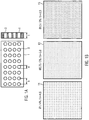
- the Fig. 1A shows a schematic drawing of a perforated film 1.
- the in Figure 1 has a uniform, lattice-like structure with a hole spacing b.
- the hole spacing is measured from the center / center of the hole to the center of the hole.
- Figure 1A only a distance b in one direction, typically horizontal here, should be understood that the distance predefined perpendicular to it should also have the value b.
- the hole diameter of the round holes 3 of the Figure 1A is marked with d.
- Figure 1A also shows a side section of the film 1 of the Figure 1A .
- the thickness of the film is denoted by t.
- the thickness of the film can range from 0.5 ⁇ m to 200 ⁇ m with regard to the following Figure 2-4 be chosen.
- the film with the reference number 11 comprises a uniform, lattice-like structure of the holes 3 in the film 11.
- the thickness of the film is 0.1 mm purely by way of example.
- the hole diameter of the film is 1 mm.
- the hole spacing b of the holes in the film 11 is 4.6 mm.
- the proportion of holes in the holes 3 in the film 11 is 4%.
- the film with the reference number 13 in turn comprises a uniform, lattice-like structure of the holes 3 in the film 13.
- the thickness of the film is 0.1 mm purely by way of example.
- the hole diameter is 0.75 mm.
- the hole spacing b of the holes in the film 13 is 3.8 mm for this example.
- the percentage of holes is 3%.
- the film with the reference number 15 in turn comprises a uniform, lattice-like structure of the holes 3 in the film 15.
- the thickness of the film is 0.1 mm purely by way of example.
- the hole diameter of the film is 0.5 mm.
- the hole spacing b of the holes in the film 11 is 2.5 mm for this example.
- the proportion of holes in the holes 3 in the film 15 is 3%. Measurements and simulation calculations have shown that the film 15 absorbs both vertically incident sound and diffusely incident sound significantly better than a standard film with a hole percentage of 0.04% or even 0.01%. Vertical sound is measured / simulated using a Kundt tube. Diffuse incident sound is measured / simulated by the sound falling on the film of the sound absorber without a preferred direction.
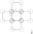
- the Figure 2 shows a schematic diagram of a unit cell of a film that the in Figure 1B shown films 11, 13, and 15 may correspond. Shown is a uniform, lattice-like hole structure with holes 3, the centers of which lie on the corners of a square with the edge length, that is to say the hole spacing b. As a result, a portion 3V of the hole 3 falls on the unit cell for each hole, so that the hole proportion can be calculated. If the area of the portion 3V is designated as F 3V , the hole portion results in Figure 2 as 4 x F 3V / b 2 x 100 [%].
- this concept can be extended to perforations with different hole spacings, for example a hole spacing b in one direction and a different hole spacing b 'in a direction perpendicular thereto.
- the proportion of holes can either be specified in a direction-dependent manner or averaged over a correspondingly large, perforated area.
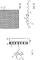
- FIG 3 is a simple structure for using a sound absorber according to the present invention outlined.
- a sound source 50 is shown which emits sound 52.
- the sound source can be, for example, an engine, for example an internal combustion engine.
- the internal combustion engine can include an exhaust gas turbocharger.
- the sound absorber 100 is in the Figure 3 sketched at a distance D from the sound source 50.
- the sound absorber 100 of the Figure 3 comprises a film 101 which corresponds to the films as in Figure 1B outlined, can correspond.
- the film 101 has holes 3.
- the holes can, as in Figure 1B outlined, have a regular perforation.
- the sound absorber 100 of the Figure 3 may further comprise an insulating body 103.
- This can be a non-woven or non-woven fabric. This can be attached, for example, on one side of the film 101, preferably immediately behind it or at a short distance of a few millimeters.
- the fleece can comprise fiber fabrics, such as mineral fibers, such as silicate fibers and / or glass fibers and / or ceramic fibers, which are preferably twisted.
- the fiber fabric can also be glued.
- the nonwoven can also be provided with a binder and pressed into a shape corresponding to the sound absorber 100 by heat.
- a fleece 103 as in Figure 3 is shown with the foils as in Figure 1B shown combinable.
- the Figure 4 shows a film 21 which the films, as in the Figures 1B - 3 discussed, can correspond.
- the film 21 is in turn perforated with holes 3. Similar to the films 11, 13, and 15 of the Figure 1B the perforation of the film is again uniform and grid-like, i.e. square here.
- the film 21 comprises an embossing, also referred to as calotting or embossing.
- embossing ie the maxima or "mountain peaks" of the embossing, are identified by reference numeral 23.
- the distance between the maxima is again uniform and grid-like.
- a determination of the proportion of the maxima per standard area or unit cell can be carried out analogously to the determination of the proportion of holes, as with the aid of Figure 2 discussed.
- the structure of the perforation and the embossing are essentially the same in this example.
- the Figure 4B shows a side view of the film 21, which is already in Figure 4A was shown.
- the sketched sound absorber can be used in a vehicle to suitably absorb sound generated in the engine compartment, for example from the engine or from a turbocharger.
Landscapes
- Engineering & Computer Science (AREA)
- Physics & Mathematics (AREA)
- Acoustics & Sound (AREA)
- Chemical & Material Sciences (AREA)
- Combustion & Propulsion (AREA)
- Mechanical Engineering (AREA)
- General Engineering & Computer Science (AREA)
- Soundproofing, Sound Blocking, And Sound Damping (AREA)
- Exhaust Silencers (AREA)
- Building Environments (AREA)
Description
- Die Erfindung betrifft einen Schallabsorber, insbesondere für Verbrennungsmotoren, gemäß dem Patentanspruch 1 sowie ein entsprechendes Verfahren gemäß dem Patentanspruch 10.
- Turbolader, auch Abgasturbolader, kurz ATL, genannt, dienen der Leistungssteigerung von Verbrennungsmotoren durch Erhöhung des Treibstoffgemischdurchsatzes pro Arbeitstakt des Verbrennungsmotors. Bei Verbrennungsmotoren, etwa Turboladern, entstehender Schall kann bei Fahrzeugen, etwa Pkw, die Umwelt und oder die Insassen des Fahrzeugs beeinträchtigen oder zumindest als unangenehm empfunden werden, so dass der Fahrkomfort beeinträchtigt werden kann oder, bei längerer Schalleinwirkung, etwa bei längeren Fahrten, sogar eine zusätzliche Belastung der Insassen sich einstellen kann.
- Angesichts der oben genannten Probleme und des diskutierten Stands der Technik ist es Aufgabe einen Schallabsorber insbesondere für Verbrennungsmotoren bereitzustellen, der eine verbesserte Absorption des Schalls bereitstellt. Schallabsorber mit zumindest einer perforierten Metallfolie und/oder einem Dämmkörper sind aus
DE19818873 ,WO2004045843 ,WO03021096 WO0046493 WO2008141380 oderWO2008028637 bekannt. - Diese Aufgabe wird mit einem Schallabsorber entsprechend des Patentanspruchs 1 gelöst. Die Aufgabe wird ebenfalls durch ein entsprechendes Verfahren gemäß Patentanspruch 10 gelöst.
- Die Erfindung stellt einen Schallabsorber zur Absorption von Schall, insbesondere für einen Verbrennungsmotor bereit, umfassend: eine perforierte Folie, aus Metall, mit einer Perforation mit einem Lochanteil von 3 - 5 %.
- Als Perforation wird hier die Durchlochung der Folie verstanden. Dabei werden typischerweise etwaige Grate entfernt, so dass typischerweise keine durch die Lochung entstandenen, möglicherweise nur auf einer Seite der Oberfläche ausgebildeten Artefakte auftreten. Durch die geeignete Wahl der Perforation entsteht ein Lochanteil der Folie der besonders effizient Schall mittels der Folie absorbieren kann. Lochanteile von 3-5% können besonders effizient sein. Als Lochanteil soll in diesem Fall das Verhältnis einer gewählten, gelochten Fläche oder eines gelochten Bereiches der Folie zu einem entsprechend gewählten nicht gelochten Bereich betrachtet werden. Sofern der Lochung eine Periodizität oder gitterartige Struktur unterliegt, sollte jeweils in Einheiten von einer Periode verglichen werden. Die betrachteten Flächen sollten zusammenhängend und nicht konkav sein. Typischerweise kann ein Rechteck oder Quadrat oder einer Raute/Parallelogramm verwendet werden, die der Struktur der Perforation entsprechen. Es soll ausdrücklich der gelochte Bereich einer Folie betrachtet werden. Bei Folien, die beispielsweise einen ungelochten Randbereich besitzen, sollte der ungelochte Randbereich in der Regel nicht betrachtet werden.
- Die verwendete Folie ist aus Metall, es können beispielsweise dünne Metallfolien mit einer Dicke von 0.5 µm bis hin zu 200 µm verwendet werden. Es sind aber auch andere Werte möglich. Es ist ebenso möglich, nicht Gegenstand der Erfindung, hitzebeständige Kunststoffe zu verwenden.
- In dem Schallabsorber kann die Folie Löcher der Perforation mit einem Lochdurchmesser zwischen 0.5 mm und 1 mm aufweisen.
- Der Lochdurchmesser ist einer der Parameter, die den Lochanteil steuern können. Dabei ist im Hinblick auf Schallabsorption und Durchlässigkeit einer Folie der Lochdurchmesser zwischen 0.5 mm und 1 mm effizient. Des Weiteren kann der Lochabstand betrachtet werden, wobei in der Regel von Lochmitte zu Lochmitte gemessen wird.
- In dem Schalldurchmesser kann der Lochdurchmesser der Perforation im Wesentlichen konstant sein.
- Häufig werden die Lochdurchmesser der Perforation konstant sein, d.h. alle Löcher der Folie haben im Wesentlichen den gleichen Durchmesser. Es versteht sich, dass es möglich sein kann, mehrere Lochdurchmesser zu haben. Typischerweise wird die Zahl aber auf wenige Lochdurchmesser beschränkt sein. Im Sinne einer Fertigung ist es am wenigsten aufwändig, nur einen Lochdurchmesser vorzusehen.
- In dem Schallabsorber kann die Perforation gitterartig sein, insbesondere regelmäßig gitterförmig.
- Typischerweise ist die Perforation gitterartig oder sogar regelmäßig gitterartig. D.h. die Perforation kann eine einfache rechteckige oder sogar quadratische Struktur aufweisen, wobei jede der vier Ecken gelocht ist.
- Die Folie kann aus mehreren Teilfolien zusammengesetzt sein, wobei die Teilfolien miteinander verschweißt oder gefalzt sein können.
- Ein Schallabsorber oder schallabsorbierende Struktur kann aus mehreren Teilfolien zu einer Fläche oder einem Körper im Raum zusammengesetzt werden. Die Teilfolien, die diesen Körper oder diese Struktur bilden, können dabei geeignet zusammengesetzt werden, etwa durch Falzen oder Verschweißen.
- Jede der Teilfolien kann einen unterschiedlichen Lochanteil aufweisen.
- Es versteht sich, dass die Teilfolien jeweils einen unterschiedlichen Lochanteil aufweisen. Es ist möglich, dass einige diese Teilfolien nicht perforiert sind.
- Der Schallabsorber umfasst ferner ein Vlies, wobei das Vlies ein Fasergewebe umfasst, wobei das Fasergewebe mineralische Fasern, wie etwa Silikatfasern und/oder Glasfasern und/oder keramischen Fasern umfasst, die verzwirnt sind.
- Das Vlies wird typischerweise im Schallabsorber in der Nähe, bei einer Folie typischerweise auf einer Seite der Folie angebracht. Dabei kann das Vlies Schall, der durch die Löcher der Folie hindurch tritt, absorbieren. Es ist ebenso möglich, dass das Vlies der die Folie in zumindest einigen Bereichen umgibt.
- In dem Schallabsorber weist die perforierte Folie zusätzlich zumindest teilweise eine Prägung mit einem Prägemuster auf, so dass eine reliefartige Struktur an der Oberfläche der Folie entsteht.
- Die Prägung soll zusätzlich zur Perforation verstanden sein. Andere Bezeichnungen für eine Prägung können Kalottierung oder Embossing sein. Es entsteht eine reliefartige Struktur an der Oberfläche der Folie, die zusätzlich zu Perforation an der Folie, d.h. an der Oberfläche der Folie Schall absorbieren kann. Die reliefartige "Berg- u. Tal"-Struktur kann bei der Herstellung geeignet an zu absorbierende Frequenzbereiche des Schalls angepasst werden.
- Das Prägemuster weist eine Prägetiefe im Bereich von 0.2 - 2 mm auf.
- Die Prägetiefe kann im Wesentlichen konstant sein.
- Das Prägemuster kann gitterartig sein, insbesondere regelmäßig gitterartig.
- Die Prägetiefe kann unterschiedlich sein oder sie kann konstant sein oder sogar gitterartig oder regelmäßig gitterartig. Dabei kann das Prägemuster unabhängig von der Perforation sein. Ähnlich wie bei der Perforation der Löcher werden Abstände typischerweise von der Mitte, also dem höchsten Punkt einer Struktur zur entsprechenden Mitte einer weiteren Struktur gemessen. Das Prägemuster kann mit der Perforation übereinstimmt.
- Das Prägemuster kann in seiner Struktur und/oder seiner Periodizität mit der Perforation der Folie übereinstimmen. Dabei können beide aber trotzdem unabhängig voneinander sein. Es ist ebenso möglich dass beide übereinstimmen und übereinanderliegen, d.h. dort, wo insbesondere in einer regelmäßigen Perforation ein Loch in der Folie vorhanden ist, ist ebenso eine geprägte Struktur, etwa eine bergartige Spitze der Prägung.
- Auch hier kann die Prägung variabel oder nur in Teilbereichen der Folie erfolgen. Sofern eine eindeutige Schallquelle mit einer Schallrichtung bestimmbar ist, kann auch die Prägung in Abhängigkeit von der Entfernung des Schallabsorbers von der Schallquelle bezogen auf die Schallrichtung variiert werden.
- Die Erfindung stellt ferner ein Verfahren bereit zur Herstellung eines Schallabsorbers zur Absorption von Schall für einen Verbrennungsmotor, mit den Schritten des Anspruchs 10.
- Dabei können geeignete Werkzeuge, etwa in ihrer Länge variierbare Nadeln verwendet werden, um die Folie zu lochen, nachdem bereits ein Prägemuster aufgeprägt ist. Hierdurch kann die Prägung bereits vor dem Lochen, d.h. Perforieren der Folie erfolgen, was fertigungstechnisch von Vorteil ist. Dabei ist die Lochungsrichtung für das Lochen der Folie, d.h. von welcher Seite die Folie gelocht wird, nicht entscheidend.
- Ein weiterer Aspekt der Erfindung betrifft die Verwendung eines Schallabsorbers wie oben beschrieben zur Schallabsorption von Schall eines Turboladers in einem Motorraum eines Fahrzeugs.
- Ein weiterer Aspekt der Erfindung betrifft ein Fahrzeug mit einem Motorraum, der einen Motor, insbesondere einen Verbrennungsmotor mit einem Turbolader, umfasst sowie einen Schallabsorber wie oben beschrieben.
- Der Erfindungsgegenstand wird anhand der nachfolgenden Zeichnungen beispielhaft erläutert.
- Es zeigen:
- Fig. 1A:
- eine Schemazeichnung einer perforierten Folie eines Schallabsorbers.
- Fig. 1B:
- drei Beispiele für eine perforierte Folie eines Schallabsorbers entsprechend der vorliegenden Erfindung.
- Fig. 2:
- eine Einheitszelle einer Folie wie in
Figur 1 skizziert. - Fig. 3
- eine Schnittzeichnung eines erfindungsgemäßen Schallabsorbers entsprechend der vorliegenden Erfindung.
- Fig. 4A
- eine Schemazeichnung einer Folie mit einer Prägung/Embossing sowie einer Perforation.
- Fig. 4B
- eine Seitenansicht der Folie aus
Figur 4A . - Die
Fig. 1A zeigt eine Schemazeichnung einer perforierten Folie 1. Die inFigur 1 weist eine gleichmäßige, gitterartige Struktur mit einem Lochabstand b auf. Der Lochabstand wird von Lochzentrum/-mitte zu Lochmitte gemessen. ObgleichFigur 1A nur einen Abstand b in einer Richtung, hier typischerweise horizontal, zeigt, soll verstanden sein, dass auch der senkrecht dazu vorgegebene Abstand den Wert b haben soll. Der Lochdurchmesser der runden Löcher 3 derFigur 1A ist mit d bezeichnet. -
Figur 1A zeigt außerdem einen seitlichen Schnitt der Folie 1 derFigur 1A . Die Dicke der Folie ist mit t bezeichnet. Die Dicke der Folie kann mit 0.5 µm bis hin zu 200 µm im Hinblick auf die nachfolgendenFigur 2 - 4 gewählt sein. - In
Figur 1B sind drei Beispiele von perforierten Folien gezeigt, die mit den Bezugszeichen 11, 13 und 15 bezeichnet sind. - Die Folie mit dem Bezugszeichen 11 umfasst eine gleichmäßige, gitterartige Struktur der Löcher 3 der Folie 11. Die Dicke der Folie beträgt rein beispielhaft 0,1 mm. Der Lochdurchmesser der Folie beträgt 1 mm. Der Lochabstand b der Löcher der Folie 11 beträgt 4,6 mm. Der Lochanteil der Löcher 3 der Folie 11 beträgt 4 %. Messungen und Simulationsrechnungen haben ergeben, dass die Folie 11 sowohl senkrecht einfallenden Schall als auch diffus einfallenden Schall deutlich besser absorbiert als eine serienmäßige Folie mit einem Lochanteil von 0.04 % oder gar 0,01 %. Dabei wird senkrecht einfallender Schall mit Hilfe eines Kundtschen Rohres gemessen/simuliert. Diffus einfallender Schall wird gemessen / simuliert, indem der Schall ohne Vorzugsrichtung auf die Folie des Schallabsorbers einfällt.
- Die Folie mit dem Bezugszeichen 13 umfasst wiederum eine gleichmäßige, gitterartige Struktur der Löcher 3 der Folie 13. Die Dicke der Folie beträgt rein beispielhaft 0,1 mm. Hier beträgt der Lochdurchmesser 0,75 mm. Der Lochabstand b der Löcher der Folie 13 beträgt für dieses Beispiel 3,8 mm. Der Lochanteil beträgt 3 %. Messungen und Simulationsrechnungen haben ergeben, dass die Folie sowohl senkrecht einfallenden Schall als auch diffus einfallenden Schall deutlich besser absorbiert als die oben erwähnten serienmäßigen Folien. Die Messungen sind analog zu denen für die Folie 11.
- Die Folie mit dem Bezugszeichen 15 umfasst wiederum eine gleichmäßige, gitterartige Struktur der Löcher 3 der Folie 15. Die Dicke der Folie beträgt rein beispielhaft 0,1 mm. Der Lochdurchmesser der Folie beträgt 0,5 mm. Der Lochabstand b der Löcher der Folie 11 beträgt für dieses Beispiel 2,5 mm. Der Lochanteil der Löcher 3 der Folie 15 beträgt 3 %. Messungen und Simulationsrechnungen haben ergeben, dass die Folie 15 sowohl senkrecht einfallenden Schall als auch diffus einfallenden Schall deutlich besser absorbiert als eine serienmäßige Folie mit einem Lochanteil von 0.04 % oder gar 0,01 %. Dabei wird senkrecht einfallender Schall mit Hilfe eines Kundtschen Rohres gemessen/simuliert. Diffus einfallender Schall wird gemessen / simuliert, indem der Schall ohne Vorzugsrichtung auf die Folie des Schallabsorbers einfällt.
- Die
Figur 2 zeigt eine Prinzipskizze einer Einheitszelle einer Folie, die den inFigur 1B gezeigten Folien 11, 13, und 15 entsprechen kann. Gezeigt ist eine gleichmäßige, gitterartige Lochstruktur mit Löchern 3, deren Zentren/Mittelpunkte auf den Ecken eines Quadrats mit der Kantenlänge, also dem Lochabstand b liegen. Dadurch fällt für jedes Loch jeweils ein Anteil 3V des Lochs 3 auf die Einheitszelle, so dass der Lochanteil berechnet werden kann. Wenn die Fläche des Anteils 3V als F3V bezeichnet wird, ergibt sich der Lochanteil inFigur 2 als 4 x F3V / b2 x 100 [%]. Es versteht sich, dass dieses Konzept erweiterbar ist auf Perforationen mit unterschiedlichen Lochabständen, beispielsweise einem Lochabstand b in einer Richtung und einem davon verschiedenen Lochabstand b' in einer Richtung senkrecht dazu. Entsprechend kann der Lochanteil entweder richtungsabhängig angegeben werden oder über eine entsprechend große, gelochte Fläche gemittelt angegeben werden. - In
Figur 3 ist ein einfacher Aufbau für die Verwendung eines Schallabsorbers entsprechender der vorliegenden Erfindung skizziert. InFigur 3 ist eine Schallquelle 50 gezeigt, die Schall 52 aussendet. Die Schallquelle kann beispielsweise ein Motor, etwa ein Verbrennungsmotor sein. Der Verbrennungsmotor kann einen Abgasturbolader umfassen. Der Schallabsorber 100 ist in derFigur 3 in einer Entfernung D von der Schallquelle 50 skizziert. Der Schallabsorber 100 derFigur 3 umfasst eine Folie 101, die den Folien, wie inFigur 1B skizziert, entsprechen kann. Die Folie 101 besitzt Löcher 3. Die Löcher können, wie inFigur 1B skizziert, eine regelmäßige Perforation besitzen. - Der Schallabsorber 100 der
Figur 3 kann ferner einen Dämmkörper 103 umfassen. Dabei kann es sich um ein Vlies oder vliesartiges Gewebe handeln. Dieses kann beispielsweise auf einer Seite der Folie 101 angebracht sein, vorzugsweise unmittelbar dahinter oder in einem geringen Abstand von wenigen Millimetern. Das Vlies kann Fasergewebe umfassen, etwa mineralische Fasern, wie etwa Silikatfasern und/oder Glasfasern und/oder keramischen Fasern umfasst, die vorzugsweise verzwirnt sind. Das Fasergewebe kann zusätzlich verklebt sein. Das Vlies kann ferner mit einem Bindemittel versehen werden und in eine dem Schallabsorber 100 entsprechende Form durch Hitze gepresst werden. Ein Vlies 103 wie inFigur 3 gezeigt ist mit den Folien wie inFigur 1B gezeigt kombinierbar. - Die
Figur 4 zeigt eine Folie 21, die den Folien, wie in denFiguren 1B - 3 diskutiert, entsprechen kann. Die Folie 21 ist wiederum perforiert mit Löchern 3. Ähnlich den Folien 11, 13, und 15 derFigur 1B ist die Lochung der Folie wiederum gleichmäßig und gitterartig, also hier quadratisch. - Zusätzlich umfasst die Folie 21 eine Prägung, auch als Kalottierung oder Embossing bezeichnet. Diese Prägung, d.h. die Maxima oder "Bergspitzen" der Prägung, sind mit dem Bezugszeichen 23 bezeichnet. Der Abstand der Maxima ist in diesem Beispiel wiederum gleichmäßig und gitterartig. Eine Bestimmung des Anteils der Maxima pro Normfläche oder Einheitszelle kann analog zu der Bestimmung der Lochanteils erfolgen, wie anhand von
Figur 2 diskutiert. Die Struktur der Perforation und der Prägung stimmen in diesem Beispiel im Wesentlichen überein. DieFigur 4B zeigt eine seitliche Ansicht der Folie 21, die bereits inFigur 4A gezeigt wurde. - Der in den
Figuren 1 - 4 skizzierte Schallabsorber kann in einem Fahrzeug verwendet werden, um im Motorraum erzeugten Schall, etwa vom Motor oder von einem Turbolader, geeignet zu absorbieren.
Claims (11)
- Schallabsorber (100) zur Absorption von Schall, insbesondere für einen Verbrennungsmotor, umfassend:eine perforierte Folie (1, 11, 13, 15, 21, 101) aus Metall mit einer Perforation mit einem Lochanteil von 3 - 5 %; und gekennzeichnet durchein Vlies (103), wobei das Vlies (103) ein Fasergewebe umfasst, wobei das Fasergewebe mineralische Fasern, wie etwa Silikatfasern und/oder Glasfasern und/oder keramischen Fasern umfasst, die verzwirnt sind;wobei die perforierte Folie (1, 11, 13, 15, 21, 101) zusätzlich zumindest teilweise eine Prägung (23) mit einem Prägemuster aufweist, so dass eine reliefartige Struktur an der Oberfläche der Folie (1, 11, 13, 15, 21, 101) entsteht;wobei das Prägemuster eine Prägetiefe im Bereich von 0.2 - 2 mm aufweist.
- Schallabsorber (100) nach Anspruch 1, wobei die Folie (1, 11, 13, 15, 21, 101) Löcher der Perforation mit einem Lochdurchmesser zwischen 0.5 mm und 1 mm aufweist.
- Schallabsorber (100) nach wenigstens einem der Ansprüche 1 und 2, wobei der Lochdurchmesser der Perforation im Wesentlichen konstant ist
- Schallabsorber (100) nach wenigstens einem der Ansprüche 1 - 3, wobei die Perforation gitterartig ist, insbesondere regelmäßig gitterförmig.
- Schallabsorber (100) nach wenigstens einem der Ansprüche 1 - 4, wobei die Folie (1, 11, 13, 15, 21, 101) aus mehreren Teilfolien zusammengesetzt ist, wobei die Teilfolien miteinander verschweißt oder gefalzt sind.
- Schallabsorber (100) nach Anspruch 5, wobei jede der Teilfolien einen unterschiedlichen Lochanteil aufweist.
- Schallabsorber (100) nach Anspruch 1, wobei die Prägetiefe im Wesentlichen konstant ist.
- Schallabsorber (100) nach einem der Ansprüche 1 oder 7, wobei das Prägemuster gitterartig ist, insbesondere regelmäßig gitterartig.
- Schallabsorber (100) nach einem der Ansprüche 1, 7 oder 8, wobei das Prägemuster mit der Perforation übereinstimmt.
- Verfahren zur Herstellung eines Schallabsorbers (100) zur Absorption von Schall für einen Verbrennungsmotor, mit den Schritten:Bereitstellen einer Folie (1, 11, 13, 15, 21, 101), vorzugsweise aus Metall;Prägen wenigstens eines Teils der Folie (1, 11, 13, 15, 21, 101), dadurch Aufprägen eines Prägemusters, so dass eine reliefartige Struktur an der Oberfläche der Folie (1, 11, 13, 15, 21, 101) entsteht, wobei das Prägemuster eine Prägetiefe im Bereich von 0.2 - 2 mm aufweist;Perforieren der Folie (1, 11, 13, 15, 21, 101), so dass die perforierte Folie (1, 11, 13, 15, 21, 101) einen Lochanteil von 3 - 5 % aufweist;Bereitstellen eines Vlieses (103), wobei das Vlies (103) ein Fasergewebe umfasst, wobei das Fasergewebe mineralische Fasern, wie etwa Silikatfasern und/oder Glasfasern und/oder keramischen Fasern umfasst, die verzwirnt sind.
- Fahrzeug mit einem Motorraum, der einen Motor, insbesondere einen Verbrennungsmotor mit einem Turbolader, umfasst sowie einen Schallabsorber (100) nach wenigstens einem der Ansprüche 1 - 9.
Priority Applications (1)
| Application Number | Priority Date | Filing Date | Title |
|---|---|---|---|
| EP12001189.5A EP2631449B1 (de) | 2012-02-22 | 2012-02-22 | Schallabsorber |
Applications Claiming Priority (1)
| Application Number | Priority Date | Filing Date | Title |
|---|---|---|---|
| EP12001189.5A EP2631449B1 (de) | 2012-02-22 | 2012-02-22 | Schallabsorber |
Publications (2)
| Publication Number | Publication Date |
|---|---|
| EP2631449A1 EP2631449A1 (de) | 2013-08-28 |
| EP2631449B1 true EP2631449B1 (de) | 2020-07-29 |
Family
ID=45833084
Family Applications (1)
| Application Number | Title | Priority Date | Filing Date |
|---|---|---|---|
| EP12001189.5A Active EP2631449B1 (de) | 2012-02-22 | 2012-02-22 | Schallabsorber |
Country Status (1)
| Country | Link |
|---|---|
| EP (1) | EP2631449B1 (de) |
Citations (1)
| Publication number | Priority date | Publication date | Assignee | Title |
|---|---|---|---|---|
| WO2008028637A1 (de) * | 2006-09-06 | 2008-03-13 | Daimler Ag | Abgasanlage eines kraftfahrzeugs |
Family Cites Families (5)
| Publication number | Priority date | Publication date | Assignee | Title |
|---|---|---|---|---|
| DE19818873C2 (de) * | 1998-04-28 | 2001-07-05 | Man B & W Diesel Ag | Hubkolbenbrennkraftmaschine |
| WO2000046493A1 (de) * | 1999-02-02 | 2000-08-10 | Rieter Automotive (International) Ag | Verfahren zum herstellen eines schallabsorbierenden isolationsteils und ein nach diesem verfahren hergestelltes isolationsteil |
| WO2003021096A1 (en) * | 2001-09-04 | 2003-03-13 | Hp-Chemie Pelzer Research And Development Ltd. | Heat-insulating and sound-absorbing lining for the engine compartment of motor vehicles |
| DE10253832A1 (de) * | 2002-11-18 | 2004-05-27 | Carcoustics Tech Center Gmbh | Schallisolierender Hitzeschutzschild |
| WO2008141380A1 (en) * | 2007-05-21 | 2008-11-27 | Bellmax Acoustic Pty Ltd | A sheet material for use in a multilayered acoustic shield |
-
2012
- 2012-02-22 EP EP12001189.5A patent/EP2631449B1/de active Active
Patent Citations (1)
| Publication number | Priority date | Publication date | Assignee | Title |
|---|---|---|---|---|
| WO2008028637A1 (de) * | 2006-09-06 | 2008-03-13 | Daimler Ag | Abgasanlage eines kraftfahrzeugs |
Also Published As
| Publication number | Publication date |
|---|---|
| EP2631449A1 (de) | 2013-08-28 |
Similar Documents
| Publication | Publication Date | Title |
|---|---|---|
| DE10347084B4 (de) | Abstimmbare, den Schall absorbierende, und die Luft filternde Dämpfungseinrichtung und Herstellungsverfahren | |
| EP1562743B1 (de) | Schallisolierender hitzeschutzschild | |
| DE69717789T2 (de) | Schallabsorbierendes element, verfahren zu dessen herstellung und seine anwendung | |
| WO2014041163A1 (de) | Mehrlagiger gelochter schallabsorber | |
| EP1784815B1 (de) | Einrichtung zur akustischen und thermischen abschirmung | |
| DE202015009565U1 (de) | Bauplatte, insbesondere Wand- oder Deckenplatte | |
| WO2022214316A1 (de) | Schalldämmendes verbundbauteil mit wabenkern und herstellverfahren hierfür | |
| EP2032393B1 (de) | Strukturbauteil, insbesondere hitzeschild | |
| DE202007017699U1 (de) | Trennwandelement | |
| DE102013206086A1 (de) | Mehrschichtiges Strukturbauteil | |
| DE102014202477A1 (de) | Akustischer Absorber und Verwendung eines derartigen akustischen Absorbers | |
| DE112016001741T5 (de) | Schalldämmmatte mit flüssig aufgebrachter, sprühbarer Beschichtung und Verfahren zu deren Herstellung | |
| DE102004050649A1 (de) | Schallabsorbierender Hitzeschild | |
| EP1995120B1 (de) | Strukturbauteil, insbesondere Hitzeschild | |
| DE102010051583A1 (de) | Schallabsorbierendes Abschirmelement | |
| EP2734417B1 (de) | Schall- und wärmeschutzschild | |
| DE4125250A1 (de) | Luftfiltermaterial zur verwendung in einem luftfilter | |
| WO2008107060A1 (de) | Schalldämpfer-dämmelement, schalldämpfer sowie verfahren zur herstellung eines schalldämpfers | |
| EP2631449A1 (de) | Schallabsorber | |
| DE102008003658A1 (de) | Wabenkörper mit strukturiertem Blechmaterial | |
| DE202008014701U1 (de) | Vorrichtung zur akustischen und thermischen Abschirmung | |
| DE102019106396B3 (de) | Hitzeschutzblech mit zweiseitiger Perforation | |
| DE29915429U1 (de) | Hitzeabschirmelement | |
| AT519010A4 (de) | Kfz-Bauteil | |
| DE102019118591A1 (de) | Schallabsorberanordnung |
Legal Events
| Date | Code | Title | Description |
|---|---|---|---|
| PUAI | Public reference made under article 153(3) epc to a published international application that has entered the european phase |
Free format text: ORIGINAL CODE: 0009012 |
|
| AK | Designated contracting states |
Kind code of ref document: A1 Designated state(s): AL AT BE BG CH CY CZ DE DK EE ES FI FR GB GR HR HU IE IS IT LI LT LU LV MC MK MT NL NO PL PT RO RS SE SI SK SM TR |
|
| AX | Request for extension of the european patent |
Extension state: BA ME |
|
| 17P | Request for examination filed |
Effective date: 20140213 |
|
| RBV | Designated contracting states (corrected) |
Designated state(s): AL AT BE BG CH CY CZ DE DK EE ES FI FR GB GR HR HU IE IS IT LI LT LU LV MC MK MT NL NO PL PT RO RS SE SI SK SM TR |
|
| STAA | Information on the status of an ep patent application or granted ep patent |
Free format text: STATUS: EXAMINATION IS IN PROGRESS |
|
| 17Q | First examination report despatched |
Effective date: 20180518 |
|
| GRAP | Despatch of communication of intention to grant a patent |
Free format text: ORIGINAL CODE: EPIDOSNIGR1 |
|
| STAA | Information on the status of an ep patent application or granted ep patent |
Free format text: STATUS: GRANT OF PATENT IS INTENDED |
|
| INTG | Intention to grant announced |
Effective date: 20200113 |
|
| GRAS | Grant fee paid |
Free format text: ORIGINAL CODE: EPIDOSNIGR3 |
|
| GRAA | (expected) grant |
Free format text: ORIGINAL CODE: 0009210 |
|
| STAA | Information on the status of an ep patent application or granted ep patent |
Free format text: STATUS: THE PATENT HAS BEEN GRANTED |
|
| AK | Designated contracting states |
Kind code of ref document: B1 Designated state(s): AL AT BE BG CH CY CZ DE DK EE ES FI FR GB GR HR HU IE IS IT LI LT LU LV MC MK MT NL NO PL PT RO RS SE SI SK SM TR |
|
| REG | Reference to a national code |
Ref country code: GB Ref legal event code: FG4D Free format text: NOT ENGLISH |
|
| REG | Reference to a national code |
Ref country code: CH Ref legal event code: EP |
|
| REG | Reference to a national code |
Ref country code: DE Ref legal event code: R096 Ref document number: 502012016239 Country of ref document: DE |
|
| REG | Reference to a national code |
Ref country code: AT Ref legal event code: REF Ref document number: 1296071 Country of ref document: AT Kind code of ref document: T Effective date: 20200815 |
|
| REG | Reference to a national code |
Ref country code: IE Ref legal event code: FG4D Free format text: LANGUAGE OF EP DOCUMENT: GERMAN |
|
| REG | Reference to a national code |
Ref country code: NL Ref legal event code: FP |
|
| REG | Reference to a national code |
Ref country code: LT Ref legal event code: MG4D |
|
| PG25 | Lapsed in a contracting state [announced via postgrant information from national office to epo] |
Ref country code: SE Free format text: LAPSE BECAUSE OF FAILURE TO SUBMIT A TRANSLATION OF THE DESCRIPTION OR TO PAY THE FEE WITHIN THE PRESCRIBED TIME-LIMIT Effective date: 20200729 Ref country code: PT Free format text: LAPSE BECAUSE OF FAILURE TO SUBMIT A TRANSLATION OF THE DESCRIPTION OR TO PAY THE FEE WITHIN THE PRESCRIBED TIME-LIMIT Effective date: 20201130 Ref country code: FI Free format text: LAPSE BECAUSE OF FAILURE TO SUBMIT A TRANSLATION OF THE DESCRIPTION OR TO PAY THE FEE WITHIN THE PRESCRIBED TIME-LIMIT Effective date: 20200729 Ref country code: BG Free format text: LAPSE BECAUSE OF FAILURE TO SUBMIT A TRANSLATION OF THE DESCRIPTION OR TO PAY THE FEE WITHIN THE PRESCRIBED TIME-LIMIT Effective date: 20201029 Ref country code: NO Free format text: LAPSE BECAUSE OF FAILURE TO SUBMIT A TRANSLATION OF THE DESCRIPTION OR TO PAY THE FEE WITHIN THE PRESCRIBED TIME-LIMIT Effective date: 20201029 Ref country code: ES Free format text: LAPSE BECAUSE OF FAILURE TO SUBMIT A TRANSLATION OF THE DESCRIPTION OR TO PAY THE FEE WITHIN THE PRESCRIBED TIME-LIMIT Effective date: 20200729 Ref country code: GR Free format text: LAPSE BECAUSE OF FAILURE TO SUBMIT A TRANSLATION OF THE DESCRIPTION OR TO PAY THE FEE WITHIN THE PRESCRIBED TIME-LIMIT Effective date: 20201030 Ref country code: HR Free format text: LAPSE BECAUSE OF FAILURE TO SUBMIT A TRANSLATION OF THE DESCRIPTION OR TO PAY THE FEE WITHIN THE PRESCRIBED TIME-LIMIT Effective date: 20200729 Ref country code: LT Free format text: LAPSE BECAUSE OF FAILURE TO SUBMIT A TRANSLATION OF THE DESCRIPTION OR TO PAY THE FEE WITHIN THE PRESCRIBED TIME-LIMIT Effective date: 20200729 |
|
| PG25 | Lapsed in a contracting state [announced via postgrant information from national office to epo] |
Ref country code: IS Free format text: LAPSE BECAUSE OF FAILURE TO SUBMIT A TRANSLATION OF THE DESCRIPTION OR TO PAY THE FEE WITHIN THE PRESCRIBED TIME-LIMIT Effective date: 20201129 Ref country code: PL Free format text: LAPSE BECAUSE OF FAILURE TO SUBMIT A TRANSLATION OF THE DESCRIPTION OR TO PAY THE FEE WITHIN THE PRESCRIBED TIME-LIMIT Effective date: 20200729 Ref country code: RS Free format text: LAPSE BECAUSE OF FAILURE TO SUBMIT A TRANSLATION OF THE DESCRIPTION OR TO PAY THE FEE WITHIN THE PRESCRIBED TIME-LIMIT Effective date: 20200729 Ref country code: LV Free format text: LAPSE BECAUSE OF FAILURE TO SUBMIT A TRANSLATION OF THE DESCRIPTION OR TO PAY THE FEE WITHIN THE PRESCRIBED TIME-LIMIT Effective date: 20200729 |
|
| PG25 | Lapsed in a contracting state [announced via postgrant information from national office to epo] |
Ref country code: RO Free format text: LAPSE BECAUSE OF FAILURE TO SUBMIT A TRANSLATION OF THE DESCRIPTION OR TO PAY THE FEE WITHIN THE PRESCRIBED TIME-LIMIT Effective date: 20200729 Ref country code: SM Free format text: LAPSE BECAUSE OF FAILURE TO SUBMIT A TRANSLATION OF THE DESCRIPTION OR TO PAY THE FEE WITHIN THE PRESCRIBED TIME-LIMIT Effective date: 20200729 Ref country code: IT Free format text: LAPSE BECAUSE OF FAILURE TO SUBMIT A TRANSLATION OF THE DESCRIPTION OR TO PAY THE FEE WITHIN THE PRESCRIBED TIME-LIMIT Effective date: 20200729 Ref country code: CZ Free format text: LAPSE BECAUSE OF FAILURE TO SUBMIT A TRANSLATION OF THE DESCRIPTION OR TO PAY THE FEE WITHIN THE PRESCRIBED TIME-LIMIT Effective date: 20200729 Ref country code: EE Free format text: LAPSE BECAUSE OF FAILURE TO SUBMIT A TRANSLATION OF THE DESCRIPTION OR TO PAY THE FEE WITHIN THE PRESCRIBED TIME-LIMIT Effective date: 20200729 Ref country code: DK Free format text: LAPSE BECAUSE OF FAILURE TO SUBMIT A TRANSLATION OF THE DESCRIPTION OR TO PAY THE FEE WITHIN THE PRESCRIBED TIME-LIMIT Effective date: 20200729 |
|
| REG | Reference to a national code |
Ref country code: DE Ref legal event code: R097 Ref document number: 502012016239 Country of ref document: DE |
|
| PG25 | Lapsed in a contracting state [announced via postgrant information from national office to epo] |
Ref country code: AL Free format text: LAPSE BECAUSE OF FAILURE TO SUBMIT A TRANSLATION OF THE DESCRIPTION OR TO PAY THE FEE WITHIN THE PRESCRIBED TIME-LIMIT Effective date: 20200729 |
|
| PLBE | No opposition filed within time limit |
Free format text: ORIGINAL CODE: 0009261 |
|
| STAA | Information on the status of an ep patent application or granted ep patent |
Free format text: STATUS: NO OPPOSITION FILED WITHIN TIME LIMIT |
|
| PG25 | Lapsed in a contracting state [announced via postgrant information from national office to epo] |
Ref country code: SK Free format text: LAPSE BECAUSE OF FAILURE TO SUBMIT A TRANSLATION OF THE DESCRIPTION OR TO PAY THE FEE WITHIN THE PRESCRIBED TIME-LIMIT Effective date: 20200729 |
|
| 26N | No opposition filed |
Effective date: 20210430 |
|
| PG25 | Lapsed in a contracting state [announced via postgrant information from national office to epo] |
Ref country code: SI Free format text: LAPSE BECAUSE OF FAILURE TO SUBMIT A TRANSLATION OF THE DESCRIPTION OR TO PAY THE FEE WITHIN THE PRESCRIBED TIME-LIMIT Effective date: 20200729 |
|
| PG25 | Lapsed in a contracting state [announced via postgrant information from national office to epo] |
Ref country code: MC Free format text: LAPSE BECAUSE OF FAILURE TO SUBMIT A TRANSLATION OF THE DESCRIPTION OR TO PAY THE FEE WITHIN THE PRESCRIBED TIME-LIMIT Effective date: 20200729 |
|
| GBPC | Gb: european patent ceased through non-payment of renewal fee |
Effective date: 20210222 |
|
| REG | Reference to a national code |
Ref country code: BE Ref legal event code: MM Effective date: 20210228 |
|
| PG25 | Lapsed in a contracting state [announced via postgrant information from national office to epo] |
Ref country code: CH Free format text: LAPSE BECAUSE OF NON-PAYMENT OF DUE FEES Effective date: 20210228 Ref country code: LI Free format text: LAPSE BECAUSE OF NON-PAYMENT OF DUE FEES Effective date: 20210228 Ref country code: LU Free format text: LAPSE BECAUSE OF NON-PAYMENT OF DUE FEES Effective date: 20210222 |
|
| PG25 | Lapsed in a contracting state [announced via postgrant information from national office to epo] |
Ref country code: GB Free format text: LAPSE BECAUSE OF NON-PAYMENT OF DUE FEES Effective date: 20210222 Ref country code: IE Free format text: LAPSE BECAUSE OF NON-PAYMENT OF DUE FEES Effective date: 20210222 |
|
| REG | Reference to a national code |
Ref country code: AT Ref legal event code: MM01 Ref document number: 1296071 Country of ref document: AT Kind code of ref document: T Effective date: 20210222 |
|
| PG25 | Lapsed in a contracting state [announced via postgrant information from national office to epo] |
Ref country code: AT Free format text: LAPSE BECAUSE OF NON-PAYMENT OF DUE FEES Effective date: 20210222 |
|
| PG25 | Lapsed in a contracting state [announced via postgrant information from national office to epo] |
Ref country code: BE Free format text: LAPSE BECAUSE OF NON-PAYMENT OF DUE FEES Effective date: 20210228 |
|
| PG25 | Lapsed in a contracting state [announced via postgrant information from national office to epo] |
Ref country code: HU Free format text: LAPSE BECAUSE OF FAILURE TO SUBMIT A TRANSLATION OF THE DESCRIPTION OR TO PAY THE FEE WITHIN THE PRESCRIBED TIME-LIMIT; INVALID AB INITIO Effective date: 20120222 Ref country code: CY Free format text: LAPSE BECAUSE OF FAILURE TO SUBMIT A TRANSLATION OF THE DESCRIPTION OR TO PAY THE FEE WITHIN THE PRESCRIBED TIME-LIMIT Effective date: 20200729 |
|
| PG25 | Lapsed in a contracting state [announced via postgrant information from national office to epo] |
Ref country code: MK Free format text: LAPSE BECAUSE OF FAILURE TO SUBMIT A TRANSLATION OF THE DESCRIPTION OR TO PAY THE FEE WITHIN THE PRESCRIBED TIME-LIMIT Effective date: 20200729 |
|
| PG25 | Lapsed in a contracting state [announced via postgrant information from national office to epo] |
Ref country code: TR Free format text: LAPSE BECAUSE OF FAILURE TO SUBMIT A TRANSLATION OF THE DESCRIPTION OR TO PAY THE FEE WITHIN THE PRESCRIBED TIME-LIMIT Effective date: 20200729 |
|
| PG25 | Lapsed in a contracting state [announced via postgrant information from national office to epo] |
Ref country code: MT Free format text: LAPSE BECAUSE OF FAILURE TO SUBMIT A TRANSLATION OF THE DESCRIPTION OR TO PAY THE FEE WITHIN THE PRESCRIBED TIME-LIMIT Effective date: 20200729 |
|
| PGFP | Annual fee paid to national office [announced via postgrant information from national office to epo] |
Ref country code: NL Payment date: 20260228 Year of fee payment: 15 |
|
| PGFP | Annual fee paid to national office [announced via postgrant information from national office to epo] |
Ref country code: DE Payment date: 20260218 Year of fee payment: 15 |
|
| PGFP | Annual fee paid to national office [announced via postgrant information from national office to epo] |
Ref country code: FR Payment date: 20260225 Year of fee payment: 15 |