EP2631455B1 - Système d'admission d'air de moteur de type en v pour véhicule - Google Patents
Système d'admission d'air de moteur de type en v pour véhicule Download PDFInfo
- Publication number
- EP2631455B1 EP2631455B1 EP20130152126 EP13152126A EP2631455B1 EP 2631455 B1 EP2631455 B1 EP 2631455B1 EP 20130152126 EP20130152126 EP 20130152126 EP 13152126 A EP13152126 A EP 13152126A EP 2631455 B1 EP2631455 B1 EP 2631455B1
- Authority
- EP
- European Patent Office
- Prior art keywords
- throttle
- air intake
- widthwise direction
- throttle body
- vehicle widthwise
- Prior art date
- Legal status (The legal status is an assumption and is not a legal conclusion. Google has not performed a legal analysis and makes no representation as to the accuracy of the status listed.)
- Active
Links
Images
Classifications
-
- F—MECHANICAL ENGINEERING; LIGHTING; HEATING; WEAPONS; BLASTING
- F02—COMBUSTION ENGINES; HOT-GAS OR COMBUSTION-PRODUCT ENGINE PLANTS
- F02D—CONTROLLING COMBUSTION ENGINES
- F02D9/00—Controlling engines by throttling air or fuel-and-air induction conduits or exhaust conduits
- F02D9/08—Throttle valves specially adapted therefor; Arrangements of such valves in conduits
- F02D9/10—Throttle valves specially adapted therefor; Arrangements of such valves in conduits having pivotally-mounted flaps
- F02D9/109—Throttle valves specially adapted therefor; Arrangements of such valves in conduits having pivotally-mounted flaps having two or more flaps
-
- F—MECHANICAL ENGINEERING; LIGHTING; HEATING; WEAPONS; BLASTING
- F02—COMBUSTION ENGINES; HOT-GAS OR COMBUSTION-PRODUCT ENGINE PLANTS
- F02B—INTERNAL-COMBUSTION PISTON ENGINES; COMBUSTION ENGINES IN GENERAL
- F02B75/00—Other engines
- F02B75/16—Engines characterised by number of cylinders, e.g. single-cylinder engines
- F02B75/18—Multi-cylinder engines
- F02B75/22—Multi-cylinder engines with cylinders in V, fan, or star arrangement
-
- F—MECHANICAL ENGINEERING; LIGHTING; HEATING; WEAPONS; BLASTING
- F02—COMBUSTION ENGINES; HOT-GAS OR COMBUSTION-PRODUCT ENGINE PLANTS
- F02D—CONTROLLING COMBUSTION ENGINES
- F02D9/00—Controlling engines by throttling air or fuel-and-air induction conduits or exhaust conduits
- F02D9/08—Throttle valves specially adapted therefor; Arrangements of such valves in conduits
- F02D9/10—Throttle valves specially adapted therefor; Arrangements of such valves in conduits having pivotally-mounted flaps
- F02D9/107—Manufacturing or mounting details
-
- F—MECHANICAL ENGINEERING; LIGHTING; HEATING; WEAPONS; BLASTING
- F02—COMBUSTION ENGINES; HOT-GAS OR COMBUSTION-PRODUCT ENGINE PLANTS
- F02M—SUPPLYING COMBUSTION ENGINES IN GENERAL WITH COMBUSTIBLE MIXTURES OR CONSTITUENTS THEREOF
- F02M35/00—Combustion-air cleaners, air intakes, intake silencers, or induction systems specially adapted for, or arranged on, internal-combustion engines
- F02M35/10—Air intakes; Induction systems
- F02M35/10006—Air intakes; Induction systems characterised by the position of elements of the air intake system in direction of the air intake flow, i.e. between ambient air inlet and supply to the combustion chamber
- F02M35/10026—Plenum chambers
- F02M35/10032—Plenum chambers specially shaped or arranged connecting duct between carburettor or air inlet duct and the plenum chamber; specially positioned carburettors or throttle bodies with respect to the plenum chamber
-
- F—MECHANICAL ENGINEERING; LIGHTING; HEATING; WEAPONS; BLASTING
- F02—COMBUSTION ENGINES; HOT-GAS OR COMBUSTION-PRODUCT ENGINE PLANTS
- F02M—SUPPLYING COMBUSTION ENGINES IN GENERAL WITH COMBUSTIBLE MIXTURES OR CONSTITUENTS THEREOF
- F02M35/00—Combustion-air cleaners, air intakes, intake silencers, or induction systems specially adapted for, or arranged on, internal-combustion engines
- F02M35/10—Air intakes; Induction systems
- F02M35/10091—Air intakes; Induction systems characterised by details of intake ducts: shapes; connections; arrangements
- F02M35/10111—Substantially V-, C- or U-shaped ducts in direction of the flow path
-
- F—MECHANICAL ENGINEERING; LIGHTING; HEATING; WEAPONS; BLASTING
- F02—COMBUSTION ENGINES; HOT-GAS OR COMBUSTION-PRODUCT ENGINE PLANTS
- F02M—SUPPLYING COMBUSTION ENGINES IN GENERAL WITH COMBUSTIBLE MIXTURES OR CONSTITUENTS THEREOF
- F02M35/00—Combustion-air cleaners, air intakes, intake silencers, or induction systems specially adapted for, or arranged on, internal-combustion engines
- F02M35/10—Air intakes; Induction systems
- F02M35/104—Intake manifolds
- F02M35/116—Intake manifolds for engines with cylinders in V-arrangement or arranged oppositely relative to the main shaft
-
- F—MECHANICAL ENGINEERING; LIGHTING; HEATING; WEAPONS; BLASTING
- F02—COMBUSTION ENGINES; HOT-GAS OR COMBUSTION-PRODUCT ENGINE PLANTS
- F02D—CONTROLLING COMBUSTION ENGINES
- F02D9/00—Controlling engines by throttling air or fuel-and-air induction conduits or exhaust conduits
- F02D9/02—Controlling engines by throttling air or fuel-and-air induction conduits or exhaust conduits concerning induction conduits
- F02D2009/0201—Arrangements; Control features; Details thereof
- F02D2009/0269—Throttle closing springs; Acting of throttle closing springs on the throttle shaft
-
- F—MECHANICAL ENGINEERING; LIGHTING; HEATING; WEAPONS; BLASTING
- F02—COMBUSTION ENGINES; HOT-GAS OR COMBUSTION-PRODUCT ENGINE PLANTS
- F02D—CONTROLLING COMBUSTION ENGINES
- F02D11/00—Arrangements for, or adaptations to, non-automatic engine control initiation means, e.g. operator initiated
- F02D11/06—Arrangements for, or adaptations to, non-automatic engine control initiation means, e.g. operator initiated characterised by non-mechanical control linkages, e.g. fluid control linkages or by control linkages with power drive or assistance
- F02D11/10—Arrangements for, or adaptations to, non-automatic engine control initiation means, e.g. operator initiated characterised by non-mechanical control linkages, e.g. fluid control linkages or by control linkages with power drive or assistance of the electric type
- F02D2011/101—Arrangements for, or adaptations to, non-automatic engine control initiation means, e.g. operator initiated characterised by non-mechanical control linkages, e.g. fluid control linkages or by control linkages with power drive or assistance of the electric type characterised by the means for actuating the throttles
-
- F—MECHANICAL ENGINEERING; LIGHTING; HEATING; WEAPONS; BLASTING
- F02—COMBUSTION ENGINES; HOT-GAS OR COMBUSTION-PRODUCT ENGINE PLANTS
- F02D—CONTROLLING COMBUSTION ENGINES
- F02D11/00—Arrangements for, or adaptations to, non-automatic engine control initiation means, e.g. operator initiated
- F02D11/06—Arrangements for, or adaptations to, non-automatic engine control initiation means, e.g. operator initiated characterised by non-mechanical control linkages, e.g. fluid control linkages or by control linkages with power drive or assistance
- F02D11/10—Arrangements for, or adaptations to, non-automatic engine control initiation means, e.g. operator initiated characterised by non-mechanical control linkages, e.g. fluid control linkages or by control linkages with power drive or assistance of the electric type
- F02D2011/101—Arrangements for, or adaptations to, non-automatic engine control initiation means, e.g. operator initiated characterised by non-mechanical control linkages, e.g. fluid control linkages or by control linkages with power drive or assistance of the electric type characterised by the means for actuating the throttles
- F02D2011/102—Arrangements for, or adaptations to, non-automatic engine control initiation means, e.g. operator initiated characterised by non-mechanical control linkages, e.g. fluid control linkages or by control linkages with power drive or assistance of the electric type characterised by the means for actuating the throttles at least one throttle being moved only by an electric actuator
-
- F—MECHANICAL ENGINEERING; LIGHTING; HEATING; WEAPONS; BLASTING
- F02—COMBUSTION ENGINES; HOT-GAS OR COMBUSTION-PRODUCT ENGINE PLANTS
- F02D—CONTROLLING COMBUSTION ENGINES
- F02D9/00—Controlling engines by throttling air or fuel-and-air induction conduits or exhaust conduits
- F02D9/08—Throttle valves specially adapted therefor; Arrangements of such valves in conduits
- F02D9/10—Throttle valves specially adapted therefor; Arrangements of such valves in conduits having pivotally-mounted flaps
- F02D9/1065—Mechanical control linkage between an actuator and the flap, e.g. including levers, gears, springs, clutches, limit stops of the like
-
- F—MECHANICAL ENGINEERING; LIGHTING; HEATING; WEAPONS; BLASTING
- F02—COMBUSTION ENGINES; HOT-GAS OR COMBUSTION-PRODUCT ENGINE PLANTS
- F02M—SUPPLYING COMBUSTION ENGINES IN GENERAL WITH COMBUSTIBLE MIXTURES OR CONSTITUENTS THEREOF
- F02M35/00—Combustion-air cleaners, air intakes, intake silencers, or induction systems specially adapted for, or arranged on, internal-combustion engines
- F02M35/10—Air intakes; Induction systems
- F02M35/10209—Fluid connections to the air intake system; their arrangement of pipes, valves or the like
- F02M35/10216—Fuel injectors; Fuel pipes or rails; Fuel pumps or pressure regulators
-
- F—MECHANICAL ENGINEERING; LIGHTING; HEATING; WEAPONS; BLASTING
- F02—COMBUSTION ENGINES; HOT-GAS OR COMBUSTION-PRODUCT ENGINE PLANTS
- F02M—SUPPLYING COMBUSTION ENGINES IN GENERAL WITH COMBUSTIBLE MIXTURES OR CONSTITUENTS THEREOF
- F02M35/00—Combustion-air cleaners, air intakes, intake silencers, or induction systems specially adapted for, or arranged on, internal-combustion engines
- F02M35/16—Combustion-air cleaners, air intakes, intake silencers, or induction systems specially adapted for, or arranged on, internal-combustion engines characterised by use in vehicles
- F02M35/162—Motorcycles; All-terrain vehicles, e.g. quads, snowmobiles; Small vehicles, e.g. forklifts
-
- F—MECHANICAL ENGINEERING; LIGHTING; HEATING; WEAPONS; BLASTING
- F02—COMBUSTION ENGINES; HOT-GAS OR COMBUSTION-PRODUCT ENGINE PLANTS
- F02M—SUPPLYING COMBUSTION ENGINES IN GENERAL WITH COMBUSTIBLE MIXTURES OR CONSTITUENTS THEREOF
- F02M69/00—Low-pressure fuel-injection apparatus ; Apparatus with both continuous and intermittent injection; Apparatus injecting different types of fuel
- F02M69/04—Injectors peculiar thereto
- F02M69/042—Positioning of injectors with respect to engine, e.g. in the air intake conduit
- F02M69/044—Positioning of injectors with respect to engine, e.g. in the air intake conduit for injecting into the intake conduit downstream of an air throttle valve
Definitions
- the present invention relates to an air intake system of a V-type engine for a vehicle, and especially relates to an air intake system of a V-type engine for a vehicle in which: a first throttle body and a second throttle body are placed between first and second banks in a V configuration which are provided to an engine main body mounted on a vehicle, the first throttle body including a first air intake passage and a first throttle valve for opening and closing the first air intake passage, the first throttle body corresponding to the first bank, the second throttle body including a second air intake passage and a second throttle valve for opening and closing the second air intake passage, the second throttle body corresponding to the second bank, the first throttle body and the second throttle body being connected to each other, and turn axis lines of the respective first and second throttle valves extending in a vehicle widthwise direction; and an electric motor which is common between the first and second throttle valves has a rotation axis line in parallel with the turn axis lines of the respective first and second throttle valves, and is interlinked with and connected to the first and second throttle valve
- Each of Japanese Patent Application Laid-open No. 2009-85111 and Japanese Patent Application Laid-open No. 2004-132290 has already made known an air intake system of a V-type engine for a vehicle in which throttle bodies corresponding to a pair of banks and provided with their respective fuel injection valves are placed between the two banks.
- the air intake system is large in size in a direction along the pivoting axes of the respective throttle valves because coil springs for biasing the throttle valves in a closing direction are placed in locations where some of the throttle valves are interposed between the coil springs and a driving force transmission place where driving force is transmitted from the electric motor to the throttle valves.
- EP 1 555 409 A1 which is a family member of JP 2004-132290 , discloses an air intake system in accordance with the preamble of claim 1, and discloses further that the second coil is placed at a side of the second throttle body, which is a side opposite from the side on which the electric motor is placed.
- An object of the present invention is to provide an air intake system of a V-type engine for a vehicle which can be made compact.
- the invention provides an air intake system of a V-type engine in accordance with claim 1.
- the electric motor is placed between the first throttle body including the first air intake passage and the second throttle body including the second air intake passage.
- the air intake system can be made compact in the direction in which the first and second throttle bodies are arranged, compared with an air intake system in which an electric motor is placed outside two throttle bodies.
- the electric motor which is a heavy object, is placed in the center portion of the air intake system in the arrangement direction. For this reason, the vibration of the electric motor can be reduced to a lower level.
- the center axis line of the second air intake passage is offset from the center axis line of the first air intake passage toward the one side in the vehicle widthwise direction; in the projection view, at least the part of the electric motor is placed within the range of offset in the vehicle widthwise direction between the points of intersection on the one side in the vehicle widthwise direction at which the turn axis lines of the first and second throttle valves intersect with the inner surfaces of the first and second air intake passages, respectively; the first coil spring for biasing the first throttle valve in the closing direction is placed at a side of the first throttle body in the vehicle widthwise direction, which is the side on which the electric motor is placed; and the second coil spring for biasing the second throttle valve in the closing direction is placed at a side of the second throttle body, which is the side opposite from the side on which the electric motor is placed, in the vehicle widthwise direction.
- the air intake system can be made compact in the vehicle widthwise direction, and the layout for placing the air intake system between the first and second banks of the V-type engine can be made easier.
- the first coil spring is placed at a side of the first throttle body in the vehicle widthwise direction, which is the side on which the electric motor is placed. For this reason, it is possible to reduce distortional deformation which occurs on the valve shaft, which is provided with the first throttle valve, due to force acting on the valve shaft from the first coil spring for biasing the first throttle valve in the closing direction and from the electric motor.
- the air intake system can be made compact in an air intake flow direction of each of the first and second air intake passages.
- the layout for placing the air intake system between the first and second banks can be made easier.
- a first fuel injection valve for injecting fuel downstream of the first throttle valve is attached to the first throttle body from the second throttle body side in a way that: in a side view, at least part of the first fuel injection valve overlaps the electric motor or a motor housing portion provided continuously to the first throttle body on the one side in the vehicle widthwise direction and housing the electric motor; and the first fuel injection valve is placed among the one ends and the opposite ends of the respective first and second throttle bodies in a direction orthogonal to the virtual plane, a second fuel injection valve for injecting fuel downstream of the second throttle valve is attached to the second throttle body from the first throttle body side in a way that the second fuel injection valve is placed among the one ends and the opposite ends of the respective first and second throttle bodies in the direction orthogonal to the virtual plane, and in the projection view obtained by projection to the horizontal plane, an opposite end portion of the electric motor in the vehicle widthwise direction or
- the first fuel injection valve for injecting the fuel downstream of the first throttle valve and the second fuel injection valve for injecting the fuel downstream of the second throttle valve are placed among the one ends and the opposite ends of the respective first and second throttle bodies in the direction orthogonal to the virtual plane passing through the turn axis lines of the respective first and second throttle valves.
- the air intake system can be made compact in the air intake flow direction of each of the first and second air intake passages.
- the first fuel injection valve is placed with the part of the first fuel injection valve overlapping the electric motor or the motor housing portion. For this reason, the second fuel injection valve is placed closer to the electric motor or the motor housing portion in the direction in which the first and second throttle bodies are arranged.
- the air intake system can be made compact in the direction in which the first and second throttle bodies are arranged. Furthermore, in the projection view obtained by projection to the horizontal plane, the opposite end portion of the electric motor in the vehicle widthwise direction or the opposite end wall of the motor housing portion in the vehicle widthwise direction is placed between the first fuel injection valve and the point of intersection on the one side in the vehicle widthwise direction, which is one of the points of intersection between the turn axis line of the first throttle valve and the inner surface of the first air intake passage; and the electric motor or the motor housing portion is placed closer to the first fuel injection valve.
- the air intake system can be made compact in the vehicle widthwise direction.
- the air intake system can be made compact in the direction in which the two throttle bodies are arranged, compared with an air intake system in which at least one of the first and second fuel injection valves is attached to at least a corresponding one of the two throttle bodies from a side opposite from the other one.
- the air intake system of a V-type engine for a vehicle wherein a tubular case main body a part of which forms the motor housing portion is connected to the first throttle body in a way that is open to the one side in the vehicle widthwise direction, the first coil spring is housed in a housing case formed from the case main body and a cover member which is fastened to the case main body in a way that closes an outer end opening portion of the case main body, a case-side fastening portion sticking out beyond the cover member towards the second throttle body is integrally provided to an outer end portion of the part, which forms the motor housing portion, of the case main body, and a connection plate is fastened to: an arm-shaped fastening portion integrally provided to the second throttle body and projecting to the one side in the vehicle widthwise direction; and the case-side fastening portion.
- the tubular case main body is connected to the first throttle body in a way that the part of the tubular case main body forms the motor housing portion;
- the cover member which, together with the case main body, forms the housing case in which to house the first coil spring is fastened to the case main body in the way that closes the outer end opening portion of the case main body;
- the case-side fastening portion sticking out beyond the cover member towards the second throttle body is integrally provided to the outer end portion of the part, which forms the motor housing portion, of the case main body;
- the connection plate is fastened to the arm-shaped fastening portions integrally provided to the second throttle body and projecting to the one side in the vehicle widthwise direction, and to the case-side fastening portion.
- the end portion of the second throttle body on the one side in the vehicle widthwise direction can be accommodated within a range in the vehicle widthwise direction which reaches an outer end of the cover member.
- the second throttle body since the distance from the second throttle body to the case-side fastening portion is short, and since the motor housing portion in which to house the electric motor is placed in the vicinity of the case-side fastening portion, the second throttle body is capable of effectively reducing the amplitude of vibration of the electric motor and the motor housing portion which occurs due to the vibration of the vehicle body; and the connection plate can be made smaller.
- a first connection plate 11 of an embodiment corresponds to the connection plate of the present invention.
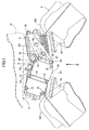
- FIG. 1 is a side view of an intake system and an essential part of an engine main body
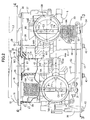
- FIG. 2 is a view seen from a direction of an arrow 2 in FIG. 1 in a state where a part of the intake system is cut out
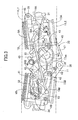
- FIG. 3 is a sectional view taken along a line 3-3 in FIG. 2
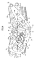
- FIG. 4 is a sectional view taken along a line 4-4 in FIG. 2 .
- an engine main body 6 built in a V-type twin-cylinder configuration is mounted on a two-wheeled motor vehicle which is a type of vehicle.
- This engine main body 6 includes a first bank BA and a second bank BB which form a V shape by separating from each other in a front-rear direction of the two-wheeled motor vehicle, and is accordingly built in the V type.
- An air intake system 8 is arranged in a space between the first and second banks BA, BB of the engine main body 6.
- the air intake system 8 includes: a first throttle body 9A on the first bank BA side, whose downstream end is connected to a cylinder head 7A of the first bank BA; a second throttle body 9B on the second bank BB side, whose downstream end is connected to a cylinder head 7B of the second bank BB; and an air cleaner 10 to which upstream ends of the respective first and second throttle bodies 9A, 9B are commonly connected.
- the first and second throttle bodies 9A, 9B are connected to each other.
- the first and second throttle bodies 9A, 9B are connected to each other by means of a first connection plate 11 on one side (in this embodiment, on an upper side in FIG. 2 ) in a vehicle widthwise direction, while the first and second throttle bodies 9A, 9B are connected to each other by means of a second connection plate 12 on an another side (in this embodiment, on an lower side in FIG. 2 ) in the vehicle widthwise direction.
- the opening degree of a first air intake passage 13A included in the first throttle body 9A is controlled by a first throttle valve 14A, and the first throttle valve 14A is fixedly attached to a first valve shaft 15A which is turnably supported by the first throttle body 9A in a way that the first valve shaft 15A traverses the first air intake passage 13A.
- the opening degree of a second air intake passage 13B included in the second throttle body 9B is controlled by a second throttle valve 14B, and the second throttle valve 14B is fixedly attached to a second valve shaft 15B which is turnably supported by the second throttle body 9B in a way that the second valve shaft 15B traverses the second air intake passage 13B.
- the first and second throttle bodies 9A, 9B connected together are arranged between the first and second banks BA, BB in a way that: turn axis lines T1, T2 of the first and second throttle valves 14A, 14B, namely center axis lines of the first and second valve shafts 15A, 15B, extend in the vehicle widthwise direction; and the first and second air intake passages 13A, 13B extend in a top-bottom direction.
- the first and second throttle bodies 9A, 9B are arranged by offsetting a center axis line C2 of the second air intake passage 13B from a center axis line C1 of the first air intake passage 13A towards one side in the vehicle widthwise direction in a projection view obtained by projection to a horizontal plane.
- the first and second throttle valves 14A, 14B are driven by an electric motor 16 which is common for the valves 14, 14B.
- This electric motor 16 is arranged between the first and second throttle bodies 9A, 9B, and has a rotation axis line MC which is in parallel with the turn axis lines T1, T2 of the respective first and second throttle valves 14A, 14B, as well as is interlinked with and connected to the first and second throttle valves 14A, 14B.
- At least a part of the electric motor 16 (in this embodiment, all of the electric motor 16) is placed among one ends and opposite ends of the respective first and second throttle bodies 9A, 9B in a direction orthogonal to a first virtual plane PL1 (see FIG. 3 ) passing through the turn axis lines T1, T2 of the first and second throttle valves 14A, 14B.
- At least a part of the electric motor 16 (in this embodiment, all of the electric motor 16) is placed among upper and lower ends of the respective first and second throttle bodies 9A, 9B, that is to say, between a first horizontal line HL1 passing through the upper ends of the respective first and second throttle bodies 9A, 9B and a second horizontal line HL2 passing through the lower ends of the respective first and second throttle bodies 9A, 9B.
- At least a part of the electric motor 16 (in this embodiment, a part of the electric motor 16) is placed within an offset range W1 in the vehicle widthwise direction between a point of intersection P1 on the one side in the vehicle widthwise direction, which is one of the points of intersection P1, P2 between the turn axis line T1 of the first throttle valve 14A and an inner surface of the first air intake passage 13A, and a point of intersection P3 on the one side in the vehicle widthwise direction, which is one of the points of intersection P3, P4 between the turn axis line T2 of the second throttle valve 14B and an inner surface of the second intake passage 13B.
- the electric motor 16 is housed in a motor housing portion 17a which is provided continuously to the first throttle body 9A on the one side in the vehicle widthwise direction and which sticks out beyond the second throttle body 9B to the one side in the vehicle widthwise direction in the projection view obtained by projection to the horizontal plane.
- a tubular case main body 17 a part of which forms the motor housing portion 17a is connected to the first throttle body 9A, for example by fastening or the like, in a way that the case main body 17 sticks out beyond the first throttle body 9A to the one side in the vehicle widthwise direction.
- a housing case 20 is formed from: the case main body 17; and a cover member 18 fastened to the case main body 17 by means of multiple screw members 19, 19, ... in a way that closes an outer end opening portion of the case main body 17.
- a speed reducing gear mechanism 22 is provided between the electric motor 16 housed in the motor housing portion 17a and the first valve shaft 15A.
- the speed reducing gear mechanism 22 is housed in the inside of the housing case 20 as well.
- the speed reducing gear mechanism 22 is formed from: a driving gear 24 fixed to a motor shaft 23 of the electric motor 16; a first idle gear 25 in mesh with the driving gear 24; a second idle gear 26 rotating integrally with the first idle gear 25; and a sector gear 27 fixed to one end portion of the first valve shaft 15A in a way that the sector gear 27 is in mesh with the second idle gear 26.
- the first and second idle gears 25, 26 are rotatably supported by an idle shaft 28 which is provided between the case main body 17 and the cover member 18.
- first throttle valve 14A is biased in a closing direction by a first coil spring 29 which is a torsion spring.
- the first coil spring 29 provided between the housing case 20 and the sector gear 27 is housed in the inside of the housing case 20 in a way that surrounds the first valve shaft 15A. In other words, the first coil spring 29 is placed at one side of the first throttle body 9A in the vehicle widthwise direction.
- a first straight line L1 which joins the turn axis line T1 of the first throttle valve 14A and the rotation axis line MC of the electric motor 16 in a side view, obliquely intersects with a second virtual plane PL2, which is orthogonal to the center axis line C1 of the first air intake passage 13A and passes through the turn axis line T1 of the first throttle valve 14A in the side view, at an angle ⁇ to the cylinder head 7A side of the first bank BA (in this embodiment, to the lower side).
- the rotation axis line MC of the electric motor 16 is placed closer to the cylinder head 7A of the first bank BA (in this embodiment, in a lower side) than the second virtual plane PL2.
- the opposite end portion of the first valve shaft 15A projects from the first throttle body 9A on the opposite side in the vehicle widthwise direction, and a first lever 31 is fixed to the opposite end portion of the first valve shaft 15A.
- an end portion of the second valve shaft 15B projects from the second throttle body 9B on the opposite side in the vehicle widthwise direction, and a second lever 32 is fixed to the end portion of the second valve shaft 15B which projects from the second throttle body 9B.
- the second throttle valve 14B is biased in the closing direction by a second coil spring 30 which is a torsion spring.
- the second coil spring 30 to be provided between the second lever 32 and the second throttle body 9B is placed between the second lever 32 and the second throttle body 9B while surrounding the second valve shaft 15B.
- the second coil spring 30 is placed at the side of the second throttle body 9B in the vehicle width widthwise direction, which is a side opposite from a side on which the electric motor 16 is placed.
- One end portion of a link 33 is connected to the first lever 31 at a position offset from the center axis line of the first valve shaft 15A, and a link-movement mechanism 34 for turning the second lever 32 and the second valve shaft 15B in response to a longitudinal movement of the link 33 which takes place in connection with the turn of the first valve shaft 15A and the first lever 31 is provided between the opposite end portion of the link 33 and the second lever 32.
- a case-side fastening portion 35 sticking out beyond the cover member 18 towards the second throttle body 9B is integrally provided to an outer end part, of a portion forming the motor housing portion 17a, of the case main body 17 connected to the first throttle body 9A.
- the second throttle body 9B is integrally provided with, for example, two arm-shaped fastening portions 36, 37 which project toward the one side in the vehicle widthwise direction.
- the first connection plate 11 is fastened to the arm-shaped fastening portions 36, 37 and the case-side fastening portion 35 by means of bolts 38, 38, ....
- the second connection plate 12 is placed in a way that covers the first lever 31, the second lever 32, the link 33 and the link-movement mechanism 34 from the lateral side.
- the second connection plate 12 is connected by means of bolts 43, 43, ... to: paired arm-shaped fastening portions 39, 40 integrally provided to the first throttle body 9A and projecting to the opposite side in the vehicle widthwise direction; and paired arm-shaped fastening portions 41, 42 integrally provided to the second throttle body 9B and projecting to the opposite side in the vehicle widthwise direction.
- a first fuel injection valve 44A is attached to the first throttle body 9A.
- a second fuel injection valve 44B is attached to the second throttle body 9B.
- the first fuel injection valve 44A is attached to the first throttle body 9A while, in the projection view obtained by projection to the horizontal plane, being orthogonal to the turn axis line T1 of the first throttle valve 14A and having a center axis line F1 passing through the center axis line C1 of the first air intake passage 13A, and in a way that the first fuel injection valve 44A injects fuel downstream of the first throttle valve 14A.
- the second fuel injection valve 44B is attached to the second throttle body 9B while, in the projection view, being orthogonal to the turn axis line T2 of the second throttle valve 14B and having a center axis line F2 passing through the center axis line C2 of the second air intake passage 13B, and in a way that the second fuel injection valve 44B injects fuel downstream of the second throttle valve 14B.
- first fuel injection valve 44A is placed between the one ends and the opposite ends of the respective first and second throttle bodies 9A, 9B, that is to say, between the first and second horizontal lines HL1, HL2, in the direction orthogonal to the first virtual plane PL1 passing through the turn axis lines T1, T2 of the respective first and second throttle valves 14A, 14B, with at least part of the first fuel injection valve 44A overlapping the electric motor 16 or the motor housing portion 17a (in this embodiment, only the motor housing portion 17a) in a side view in the vehicle widthwise direction.
- the second fuel injection valve 44B is also placed between the one ends and the opposite ends of the respective first and second throttle bodies 9A, 9B, that is to say, between the first and second horizontal lines HL1, HL2, in the direction orthogonal to the first virtual plane PL1.
- either an opposite end portion of the electric motor 16 in the vehicle widthwise direction or an opposite end wall 17aa of the motor housing portion 17a in the vehicle widthwise direction, particularly the opposite end wall 17aa of the motor housing portion 17a in this embodiment is placed within a range W2 between the first fuel injection valve 44A and the point of intersection P1 on the one side in the vehicle widthwise direction, which is one of the points of intersection P1, P2 between the turn axis line T1 of the first throttle valve 14A and the inner surface of the first air intake passage 13A.
- the second fuel injection valve 44B is placed in a location offset from the first fuel injection valve 44A towards the one side in the vehicle widthwise direction by a distance corresponding to the amount of offset between the center axis lines C1, C2 of the respective first and second air intake passages 13A, 13B in the vehicle widthwise direction.
- a fuel supply pipe 47 for supplying fuel from a fuel tank, which is not illustrated, to the first and second fuel injection valves 44A, 44B is connected to the fuel supply connecting pipe 46.
- a vacant space S is formed among mutually-adjacent upper end portions of the respective first and second throttle bodies 9A, 9B, an upper end of the first connection plate 11 and an upper end of the housing case 20, on the basis of the design in which the first straight line L1 joining, in the side view, the rotation axis line MC of the electric motor 16, which is placed under the second virtual plane PL2, and the turn axis line T1 of the first throttle valve 14A obliquely intersects, at the angle ⁇ , with the second virtual plane PL2 which is orthogonal to the center axis line C1 of the first air intake passage 13A and passing through the turn axis line T1 of the first throttle valve 14A in the side view.
- the fuel supply pipe 47 is laid in a way that passes the vacant space S.
- the electric motor 16 is placed between the first throttle body 9A including the first air intake passage 13A and the second throttle body 9B including the second air intake passage 13B.
- the air intake system 8 can be made compact in a direction in which the first and second throttle bodies 9A, 9B are arranged (hereinafter referred to as an "arrangement direction"), compared with an air intake system having the electric motor 16 outside the two throttle bodies 9A, 9B.
- the placement of the electric motor 16, which is a heavy object, in the center portion of the air intake system 8 in the arrangement direction makes it possible to reduce the vibration of the air intake system 8 to a lower level.
- the center axis line C2 of the second air intake passage 13B is offset from the center axis line C1 of the first air intake passage 13A towards the one side in the vehicle widthwise direction; at least the part (in this embodiment, only the part) of the electric motor 16 is placed within the range W1 of the offset in the vehicle widthwise direction between the point of intersection P1 on the one side in the vehicle widthwise direction, which is one of the points of intersection P1, P2 between the turn axis line T1 of the first throttle valve 14A and the inner surface of the first air intake passage 13A, and the point of intersection P3 on the one side in the vehicle widthwise direction, which is one of the points of intersection P3, P4 between the turn axis line T2 of the second throttle valve 14B and the inner surface of the second air intake passage 13B; the first coil spring 29 for biasing the first throttle valve 14A in the closing direction is placed at the side of the first throttle body 9A in the vehicle widthwise direction, which is the side on which
- the air intake system 8 can be made compact in the vehicle widthwise direction, and the layout for placing the air intake system 8 between the first and second banks BA, BB of the V-type engine can be made easier.
- the first coil spring 29 is placed at the side of the first throttle body 9A in the vehicle widthwise direction, which is the side on which the electric motor 16 is placed, it is possible to reduce or eliminate distortional deformation of the first valve shaft 15A, which is provided with the first throttle valve 14A, due to a force acting on the first valve shaft 15A from the first coil spring 29 for biasing the first throttle valve 14A in the closing direction and from the electric motor 16.
- the electric motor 16 is placed among the one ends and the opposite ends of the respective first and second throttle bodies 9A, 9B in the direction orthogonal to the first virtual plane PL1 passing through the turn axis lines T1, T2 of the respective first and second throttle valves 14A, 14B, that is to say, between the first horizontal line HL1 passing through the upper ends of the respective first and second throttle bodies 9A, 9B and the second horizontal line HL2 passing through the lower ends of the respective first and second throttle bodies 9A, 9B in this embodiment.
- the air intake system 8 can be made compact in an air intake flow direction of each of the first and second air intake passages 13A, 13B.
- the layout for placing the air intake system 8 between the first and second banks BA, BB can be made easier.
- the first fuel injection valve 44A injects fuel downstream of the first throttle valve 14A while, in the projection view obtained by projection to the horizontal plane, being orthogonal to the turn axis line T1 of the first throttle valve 14A and having the center axis line F1 passing through the center axis line C1 of the first air intake passage 13A.
- the second fuel injection valve 44B injects fuel downstream of the second throttle valve 14B while, in the projection view, being orthogonal to the turn axis line T2 of the second throttle valve 14B and having the center axis line F2 passing through the center axis line C2 of the second air intake passage 13B.
- the performance of the engine which depends on the fuel injection by the first and second fuel injection valves 44A, 44B, can be maintained.
- the first and second fuel injection valves 44A, 44B are placed among the one ends and the opposite ends of the respective first and second throttle bodies 9A, 9B in the direction orthogonal to the first virtual plane PL1 passing through the turn axis lines T1, T2 of the respective first and second throttle valves 14A, 14B.
- the air intake system 8 can be made compact in the air intake flow direction of each of the first and second air intake passages 13A, 13B.
- the first fuel injection valve 44A is placed with at least a part of the first fuel injection valve 44A overlapping the electric motor 16 or the motor housing portion 17a in the side view in the vehicle widthwise direction. For this reason, the placement of the second fuel injection valve 44B closer to the electric motor 16 or the motor housing portion 17a in the direction in which the first and second throttle bodies 9A, 9B are arranged makes it possible to make the air intake system 8 compact in the direction in which the first and second throttle bodies 9A, 9B are arranged.
- either the opposite end portion of the electric motor 16 in the vehicle widthwise direction or the opposite end wall 17aa of the motor housing portion 17a in the vehicle widthwise direction is placed between the first fuel injection valve 44A and the point of intersection P1 on the one side in the vehicle widthwise direction, which is one of the points of intersection P1, P2 between the turn axis line T1 of the first throttle valve 14A and the inner surface of the first air intake passage 13A.
- Either the electric motor 16 or the motor housing portion 17a is placed closer to the first fuel injection valve 44A.
- the air intake system 8 can be made compact in the vehicle widthwise direction. Moreover, from the second throttle body 9B side, the first fuel injection valve 44A is attached to the first throttle body 9A, and from the first throttle body 9A side, the second fuel injection valve 44B is attached to the second throttle body 9B. For this reason, the air intake system 8 can be made compact in the direction in which the two throttle bodies 9A, 9B are arranged, compared with an air intake system in which at least one of the first and second fuel injection valves 44A, 44B is attached to at least a corresponding one of the two throttle bodies 9A, 9B from an opposite side of the corresponding one from the other one.
- first straight line L1 which joins the turn axis line T1 of the first throttle valve 14A and the rotation axis line MC of the electric motor 16 in the side view in the vehicle widthwise direction, obliquely intersects with the second virtual plane PL2, which is orthogonal to the center axis line C1 of the first air intake passage 13A and passes through the turn axis line T1 of the first throttle valve 14A in the side view, at the angle ⁇ to the cylinder head 7A side of the first bank BA (in this embodiment, to the lower side).
- the second fuel injection valve 44B can be placed closer to the motor housing portion 17a by using the space which is created on an opposite side of the second virtual plane PL2 from the first straight line L1, and the air intake system 8 can be made compact in the direction in which the first and second throttle bodies 9A, 9B are arranged.
- the tubular case main body 17 is connected to the first throttle body 9A in the way that a part of the case main body 17 forms the motor housing portion 17a; the cover member 18 which, together with the case main body 17, forms the housing case 20 for housing the first coil spring 29, is fastened to the case main body 17 in the way that closes the outer end opening portion of the case main body 17; the case-side fastening portion 35 sticking out beyond the cover member 18 towards the second throttle body 9B is integrally provided in the outer end part of the portion, of the case main body 17, forming the motor housing portion 17a; and the first connection plate 11 is fastened to, for example, the case-side fastening portion 35 and the paired arm-shaped fastening portions 36, 37 which are integrally provided to the second throttle body 9B and stick out towards the one side in the vehicle widthwise direction.
- the end portion of the second throttle body 9B on the one side in the vehicle widthwise direction can be accommodated within a range in the vehicle widthwise direction which reaches an outer end of the cover member 18, that is to say, inside the second straight line L2 extending in the front-rear direction while passing through the outer end of the cover member 18.
- the second throttle body 9B since the distance from the second throttle body 9B to the case-side fastening portion 35 is short, and since the motor housing portion 17a in which to house the electric motor 16 is placed in the vicinity of the case-side fastening portion 35, the second throttle body 9B is capable of effectively reducing the amplitude of vibration of the electric motor 16 and the motor housing portion 17b which occurs due to the vibration of the vehicle body; and the first connection plate 11 can be made smaller.
- the fuel supply pipe 47 for supplying the fuel to the first and second fuel injection valves 44A, 44B passes through the vacant space S which is created among the mutually-adj acent upper end portions of the respective first and second throttle bodies 9A, 9B, the upper end of the first connection plate 11 and the upper end of the housing case 20. For this reason, the fuel supply pipe 47 can be laid out with better space efficiency.
- the present invention imposes no restriction on the orientation in which the engine main body is mounted on the vehicle as long as the turn axis lines of the respective first and second throttle valves 14A, 14B extend in the vehicle width widthwise direction.
- a pair of throttle bodies connected to each other and placed between a pair of banks includes throttle valves, respectively, and an electric motor is interlinked with and connected to the throttle valves.
- At least part of an electric motor (16) placed between first and second throttle bodies (9A, 9B) is placed within a range (W1) of offset in a vehicle widthwise direction between points of intersection (P1, P3) on the one side in the vehicle widthwise direction, which are points of intersection between turn axis lines (T1, T2) of first and second throttle valves (14A, 14B) and inner surfaces of first and second air intake passages (13A, 13B), respectively, and is also placed among one ends and opposite ends of the respective first and second throttle bodies (9A, 9B) in a direction orthogonal to a virtual plane passing through the turn axis lines (T1, T2).
- a first coil spring (29) is placed at one side of the first throttle body (9A) in the vehicle widthwise direction, and a second coil spring (30) is placed at a side of the second throttle body (9B), which is a side opposite from the side on which the electric motor (16) is placed. Accordingly, the air intake system can be made compact.
Landscapes
- Engineering & Computer Science (AREA)
- Chemical & Material Sciences (AREA)
- Combustion & Propulsion (AREA)
- Mechanical Engineering (AREA)
- General Engineering & Computer Science (AREA)
- Manufacturing & Machinery (AREA)
- Control Of Throttle Valves Provided In The Intake System Or In The Exhaust System (AREA)
Claims (3)
- Système d'admission d'air d'un moteur de type en V pour un véhicule dans lequel : un premier corps de papillon (9A) et un second corps de papillon (9B) doivent être placés entre des première et secondes rangées (BA, BB) dans une configuration en V qui sont prévues sur un corps principal de moteur (6) monté sur un véhicule, le premier corps de papillon (9A) comprenant un premier passage d'admission d'air (13A) et un premier papillon des gaz (14A) pour ouvrir et fermer le premier passage d'admission d'air (13A), le premier corps de papillon (9A) correspondant à la première rangée (BA), le second corps de papillon (9B) comprenant un second passage d'admission d'air (13B) et un second papillon des gaz (14B) pour ouvrir et fermer le second passage d'air d'admission (13B), le second corps de papillon (9B) correspondant à la seconde rangée (BB), le premier corps de papillon (9A) et le second corps de papillon (9B) étant raccordés entre eux, et des lignes d'axe de rotation (T1, T2) des premier et second papillons des gaz (14A, 14B) respectifs s'étendant, dans un état monté dans le sens de la largeur du véhicule ; et un moteur électrique (16) qui est commun entre les premier et second papillons de gaz (14A, 14B) a une ligne d'axe de rotation (MC) en parallèle par rapport aux lignes d'axe de rotation (T1, T2) des premier et second papillons des gaz (14A, 14B) respectifs, et est lié avec et raccordé aux premier et second papillons des gaz (14A, 14B), dans lequel :sur une vue en projection obtenue par la projection sur un plan horizontal, les premier et second corps de papillon (9A, 9B) sont placés, à l'état monté, avec une ligne d'axe central (C2) du second passage d'admission d'air (13B) décalée d'une ligne d'axe central (C1) du premier passage d'admission d'air (13A) vers un côté dans le sens de la largeur du véhicule,sur la vue en projection, au moins une partie du moteur électrique (16) placé entre les premier et second corps de papillon (9A, 9B) est placée, à l'état monté, dans une plage (W1) de décalage dans le sens de la largeur du véhicule entre un premier point d'intersection (P1) sur le premier côté dans le sens de la largeur du véhicule et un second point d'intersection (P3) sur le premier côté dans le sens de la largeur du véhicule, le premier point d'intersection (P1) étant l'un des points d'intersection (P1, P2) entre la ligne d'axe de rotation (T1) du premier papillon des gaz (14A) et une surface interne du premier passage d'admission d'air (13A), et le second point d'intersection (P3) étant l'un des points d'intersection (P3, P4) entre la ligne d'axe de rotation (T2) du second papillon des gaz (14B) et une surface interne du second passage d'admission d'air (13B),au moins la partie du moteur électrique (16) est placée parmi les extrémités et les extrémités opposées des premier et second corps de papillon (9A, 9B) respectifs dans une direction orthogonale à un plan virtuel (PL1) passant par les lignes d'axe de rotation (T1, T2) des premier et second papillons des gaz (14A, 14B) respectifs,un premier ressort hélicoïdal (29) pour solliciter le premier papillon des gaz (14A) dans une direction de fermeture, est placé au niveau d'un côté du premier corps de papillon (9A) dans le sens de la largeur du véhicule, etun second ressort hélicoïdal (30) pour solliciter le second papillon des gaz (14B) dans une direction de fermeture, est placé au niveau d'un côté du second corps de papillon (9B) qui est un côté opposé au côté sur lequel le moteur électrique (16) est placé, dans le sens de la largeur du véhicule,caractérisé en ce que le premier ressort hélicoïdal (29) est placé sur le côté du premier corps de papillon (9A) sur lequel le moteur électrique (16) est placé.
- Système d'admission d'air d'un moteur de type en V pour un véhicule selon la revendication 1, dans lequel :une première soupape d'injection de carburant (44A) pour injecter du carburant en aval du premier papillon des gaz (14A) est fixée sur le premier corps de papillon (9A) à partir du côté du second corps de papillon (9B) de sorte que : sur une vue latérale, au moins une partie de la première soupape d'injection de carburant (44A) chevauche sur le moteur électrique (16) ou une partie de logement de moteur (17a) prévue en continu vers le premier corps de papillon (9A) sur le côté dans le sens de la largeur du véhicule et logeant le moteur électrique (16) ; et la première soupape d'injection de carburant (44A) est placée parmi les extrémités et les extrémités opposées des premier et second corps de papillon (9A, 9B) respectifs dans une direction orthogonale au plan virtuel (PL1),une seconde soupape d'injection de carburant (44B) pour injecter le carburant en aval du second papillon des gaz (14B) est fixée au second corps de papillon (9B) à partir du côté du premier corps de papillon (9A) de sorte que la seconde soupape d'injection de carburant (44B) est placée parmi les extrémités et les extrémités opposées des premier et second corps de papillon (9A, 9B) respectifs dans la direction orthogonale par rapport au plan virtuel (PL1), etsur la vue en projection obtenue par la projection sur le plan horizontal, une partie d'extrémité opposée du moteur électrique (16) dans le sens de la largeur du véhicule ou une paroi d'extrémité opposée (17aa) de la partie de logement de moteur (17a) dans le sens de la largeur du véhicule est placée entre la première soupape d'injection de carburant (44A) et le premier point d'intersection (P1) du premier côté dans le sens de la largeur du véhicule, qui est l'un des points d'intersection (P1, P2) entre la ligne d'axe de rotation (T1) du premier papillon des gaz (14A) et la surface interne du premier passage d'admission d'air (13A).
- Système d'admission d'air d'un moteur de type en V pour un véhicule selon la revendication 2, dans lequel :un corps principal de carter tubulaire (17) dont une partie forme la partie de logement de moteur (17a), est raccordé au premier corps de papillon (9A) de sorte qu'il est ouvert vers le premier côté dans le sens de la largeur du véhicule, le premier ressort hélicoïdal (29) est logé dans un carter de logement (20) formé à partir du corps principal de carter (17) et un élément de couvercle (18) qui est fixé au corps principal de carter (17) de sorte qu'il ferme une partie d'ouverture d'extrémité externe du corps principal de carter (17),une partie de fixation du côté du carter (35) étant en saillie au-delà de l'élément de couvercle (18) vers le second corps de papillon (9B) est prévue de manière solidaire sur une partie d'extrémité externe de la partie, qui forme la partie de logement de moteur (17a), du corps principal de carter (17), etune plaque de raccordement (11) est fixée sur : une partie de fixation en forme de bras (36, 37) prévue de manière solidaire sur le second corps de papillon (9B) et faisant saillie vers le premier côté dans le sens de la largeur du véhicule ; et la partie de fixation du côté du carter (35).
Applications Claiming Priority (1)
| Application Number | Priority Date | Filing Date | Title |
|---|---|---|---|
| JP2012035409A JP5899591B2 (ja) | 2012-02-21 | 2012-02-21 | 車両用v型エンジンの吸気装置 |
Publications (2)
| Publication Number | Publication Date |
|---|---|
| EP2631455A1 EP2631455A1 (fr) | 2013-08-28 |
| EP2631455B1 true EP2631455B1 (fr) | 2014-12-31 |
Family
ID=47563300
Family Applications (1)
| Application Number | Title | Priority Date | Filing Date |
|---|---|---|---|
| EP20130152126 Active EP2631455B1 (fr) | 2012-02-21 | 2013-01-22 | Système d'admission d'air de moteur de type en v pour véhicule |
Country Status (2)
| Country | Link |
|---|---|
| EP (1) | EP2631455B1 (fr) |
| JP (1) | JP5899591B2 (fr) |
Families Citing this family (2)
| Publication number | Priority date | Publication date | Assignee | Title |
|---|---|---|---|---|
| JP6270897B2 (ja) | 2016-03-30 | 2018-01-31 | 本田技研工業株式会社 | 鞍乗り型車両の過給機付き内燃機関 |
| JP2024153322A (ja) | 2023-04-17 | 2024-10-29 | 株式会社ミクニ | エンジンのスロットル装置 |
Family Cites Families (7)
| Publication number | Priority date | Publication date | Assignee | Title |
|---|---|---|---|---|
| JP4494660B2 (ja) * | 2001-03-05 | 2010-06-30 | ヤマハ発動機株式会社 | 自動二輪車におけるv型エンジンのスロットル制御装置 |
| JP2004132290A (ja) | 2002-10-11 | 2004-04-30 | Mikuni Corp | 多連スロットル装置 |
| JP2009085111A (ja) | 2007-09-29 | 2009-04-23 | Honda Motor Co Ltd | V型多気筒エンジンにおける燃料供給構造 |
| JP2009092018A (ja) * | 2007-10-10 | 2009-04-30 | Yamaha Motor Co Ltd | エンジンユニット及びそれを備えた車両 |
| JP5315281B2 (ja) * | 2010-03-31 | 2013-10-16 | 本田技研工業株式会社 | エンジン |
| JP2011247221A (ja) * | 2010-05-28 | 2011-12-08 | Keihin Corp | V型エンジンの吸気制御装置 |
| JP2011247222A (ja) * | 2010-05-28 | 2011-12-08 | Keihin Corp | 車両用v型エンジンの吸気制御装置 |
-
2012
- 2012-02-21 JP JP2012035409A patent/JP5899591B2/ja active Active
-
2013
- 2013-01-22 EP EP20130152126 patent/EP2631455B1/fr active Active
Also Published As
| Publication number | Publication date |
|---|---|
| JP5899591B2 (ja) | 2016-04-06 |
| JP2013170521A (ja) | 2013-09-02 |
| EP2631455A1 (fr) | 2013-08-28 |
Similar Documents
| Publication | Publication Date | Title |
|---|---|---|
| JP4494660B2 (ja) | 自動二輪車におけるv型エンジンのスロットル制御装置 | |
| EP1992812B1 (fr) | Motocyclette | |
| US20080078349A1 (en) | Intake device of V-type internal combustion engine | |
| EP2631455B1 (fr) | Système d'admission d'air de moteur de type en v pour véhicule | |
| US20160258395A1 (en) | Motorcycle incorporating a supercharger | |
| US8191515B2 (en) | V-type internal combustion engine including throttle valve device, and vehicle incorporating same | |
| US7690356B2 (en) | Internal combustion engine | |
| JP2009197816A (ja) | エンジン | |
| JP4916528B2 (ja) | 自動二輪車用エンジン | |
| US8042514B2 (en) | Throttle bodies and saddle-type vehicles including valved intake conduits for engine | |
| JP2009197810A (ja) | エンジン | |
| JP2001263186A (ja) | 自動二輪車 | |
| JP2013170521A5 (fr) | ||
| JP2010236407A (ja) | 自動二輪車 | |
| US8997713B2 (en) | Throttle body configured to provide turbulent air flow to a combustion chamber of an engine, and engine including same | |
| TWI664349B (zh) | 內燃機及跨坐型車輛 | |
| JP2009236098A (ja) | V型エンジンの吸気装置 | |
| US11002232B2 (en) | V-engine air intake structure | |
| JP5143275B2 (ja) | エンジン | |
| JP4916527B2 (ja) | 自動二輪車用エンジン | |
| JP2012077755A (ja) | エンジン | |
| JP2010127199A (ja) | スロットル装置 | |
| JP4916563B2 (ja) | 自動二輪車のエンジンのスロットル制御装置 | |
| JP4447420B2 (ja) | 吸気装置 | |
| JP2011247222A (ja) | 車両用v型エンジンの吸気制御装置 |
Legal Events
| Date | Code | Title | Description |
|---|---|---|---|
| PUAI | Public reference made under article 153(3) epc to a published international application that has entered the european phase |
Free format text: ORIGINAL CODE: 0009012 |
|
| 17P | Request for examination filed |
Effective date: 20130122 |
|
| AK | Designated contracting states |
Kind code of ref document: A1 Designated state(s): AL AT BE BG CH CY CZ DE DK EE ES FI FR GB GR HR HU IE IS IT LI LT LU LV MC MK MT NL NO PL PT RO RS SE SI SK SM TR |
|
| AX | Request for extension of the european patent |
Extension state: BA ME |
|
| GRAP | Despatch of communication of intention to grant a patent |
Free format text: ORIGINAL CODE: EPIDOSNIGR1 |
|
| RIC1 | Information provided on ipc code assigned before grant |
Ipc: F02D 9/10 20060101AFI20140708BHEP Ipc: F02M 35/116 20060101ALI20140708BHEP Ipc: F02M 35/10 20060101ALI20140708BHEP Ipc: F02D 9/02 20060101ALI20140708BHEP Ipc: F02D 11/10 20060101ALI20140708BHEP Ipc: F02M 35/16 20060101ALI20140708BHEP Ipc: F02M 69/04 20060101ALI20140708BHEP |
|
| INTG | Intention to grant announced |
Effective date: 20140812 |
|
| GRAS | Grant fee paid |
Free format text: ORIGINAL CODE: EPIDOSNIGR3 |
|
| GRAA | (expected) grant |
Free format text: ORIGINAL CODE: 0009210 |
|
| AK | Designated contracting states |
Kind code of ref document: B1 Designated state(s): AL AT BE BG CH CY CZ DE DK EE ES FI FR GB GR HR HU IE IS IT LI LT LU LV MC MK MT NL NO PL PT RO RS SE SI SK SM TR |
|
| REG | Reference to a national code |
Ref country code: CH Ref legal event code: EP Ref country code: GB Ref legal event code: FG4D |
|
| REG | Reference to a national code |
Ref country code: IE Ref legal event code: FG4D |
|
| REG | Reference to a national code |
Ref country code: AT Ref legal event code: REF Ref document number: 704562 Country of ref document: AT Kind code of ref document: T Effective date: 20150215 |
|
| REG | Reference to a national code |
Ref country code: DE Ref legal event code: R096 Ref document number: 602013000714 Country of ref document: DE Effective date: 20150219 |
|
| PG25 | Lapsed in a contracting state [announced via postgrant information from national office to epo] |
Ref country code: FI Free format text: LAPSE BECAUSE OF FAILURE TO SUBMIT A TRANSLATION OF THE DESCRIPTION OR TO PAY THE FEE WITHIN THE PRESCRIBED TIME-LIMIT Effective date: 20141231 Ref country code: LT Free format text: LAPSE BECAUSE OF FAILURE TO SUBMIT A TRANSLATION OF THE DESCRIPTION OR TO PAY THE FEE WITHIN THE PRESCRIBED TIME-LIMIT Effective date: 20141231 Ref country code: NO Free format text: LAPSE BECAUSE OF FAILURE TO SUBMIT A TRANSLATION OF THE DESCRIPTION OR TO PAY THE FEE WITHIN THE PRESCRIBED TIME-LIMIT Effective date: 20150331 |
|
| REG | Reference to a national code |
Ref country code: NL Ref legal event code: VDEP Effective date: 20141231 |
|
| REG | Reference to a national code |
Ref country code: LT Ref legal event code: MG4D |
|
| PG25 | Lapsed in a contracting state [announced via postgrant information from national office to epo] |
Ref country code: SE Free format text: LAPSE BECAUSE OF FAILURE TO SUBMIT A TRANSLATION OF THE DESCRIPTION OR TO PAY THE FEE WITHIN THE PRESCRIBED TIME-LIMIT Effective date: 20141231 Ref country code: LV Free format text: LAPSE BECAUSE OF FAILURE TO SUBMIT A TRANSLATION OF THE DESCRIPTION OR TO PAY THE FEE WITHIN THE PRESCRIBED TIME-LIMIT Effective date: 20141231 Ref country code: RS Free format text: LAPSE BECAUSE OF FAILURE TO SUBMIT A TRANSLATION OF THE DESCRIPTION OR TO PAY THE FEE WITHIN THE PRESCRIBED TIME-LIMIT Effective date: 20141231 Ref country code: GR Free format text: LAPSE BECAUSE OF FAILURE TO SUBMIT A TRANSLATION OF THE DESCRIPTION OR TO PAY THE FEE WITHIN THE PRESCRIBED TIME-LIMIT Effective date: 20150401 Ref country code: HR Free format text: LAPSE BECAUSE OF FAILURE TO SUBMIT A TRANSLATION OF THE DESCRIPTION OR TO PAY THE FEE WITHIN THE PRESCRIBED TIME-LIMIT Effective date: 20141231 |
|
| REG | Reference to a national code |
Ref country code: AT Ref legal event code: MK05 Ref document number: 704562 Country of ref document: AT Kind code of ref document: T Effective date: 20141231 |
|
| PG25 | Lapsed in a contracting state [announced via postgrant information from national office to epo] |
Ref country code: NL Free format text: LAPSE BECAUSE OF FAILURE TO SUBMIT A TRANSLATION OF THE DESCRIPTION OR TO PAY THE FEE WITHIN THE PRESCRIBED TIME-LIMIT Effective date: 20141231 |
|
| PG25 | Lapsed in a contracting state [announced via postgrant information from national office to epo] |
Ref country code: RO Free format text: LAPSE BECAUSE OF FAILURE TO SUBMIT A TRANSLATION OF THE DESCRIPTION OR TO PAY THE FEE WITHIN THE PRESCRIBED TIME-LIMIT Effective date: 20141231 Ref country code: CZ Free format text: LAPSE BECAUSE OF FAILURE TO SUBMIT A TRANSLATION OF THE DESCRIPTION OR TO PAY THE FEE WITHIN THE PRESCRIBED TIME-LIMIT Effective date: 20141231 Ref country code: SK Free format text: LAPSE BECAUSE OF FAILURE TO SUBMIT A TRANSLATION OF THE DESCRIPTION OR TO PAY THE FEE WITHIN THE PRESCRIBED TIME-LIMIT Effective date: 20141231 Ref country code: ES Free format text: LAPSE BECAUSE OF FAILURE TO SUBMIT A TRANSLATION OF THE DESCRIPTION OR TO PAY THE FEE WITHIN THE PRESCRIBED TIME-LIMIT Effective date: 20141231 |
|
| PG25 | Lapsed in a contracting state [announced via postgrant information from national office to epo] |
Ref country code: LU Free format text: LAPSE BECAUSE OF FAILURE TO SUBMIT A TRANSLATION OF THE DESCRIPTION OR TO PAY THE FEE WITHIN THE PRESCRIBED TIME-LIMIT Effective date: 20150122 Ref country code: AT Free format text: LAPSE BECAUSE OF FAILURE TO SUBMIT A TRANSLATION OF THE DESCRIPTION OR TO PAY THE FEE WITHIN THE PRESCRIBED TIME-LIMIT Effective date: 20141231 Ref country code: IS Free format text: LAPSE BECAUSE OF FAILURE TO SUBMIT A TRANSLATION OF THE DESCRIPTION OR TO PAY THE FEE WITHIN THE PRESCRIBED TIME-LIMIT Effective date: 20150430 Ref country code: PL Free format text: LAPSE BECAUSE OF FAILURE TO SUBMIT A TRANSLATION OF THE DESCRIPTION OR TO PAY THE FEE WITHIN THE PRESCRIBED TIME-LIMIT Effective date: 20141231 |
|
| REG | Reference to a national code |
Ref country code: DE Ref legal event code: R097 Ref document number: 602013000714 Country of ref document: DE |
|
| PG25 | Lapsed in a contracting state [announced via postgrant information from national office to epo] |
Ref country code: MC Free format text: LAPSE BECAUSE OF FAILURE TO SUBMIT A TRANSLATION OF THE DESCRIPTION OR TO PAY THE FEE WITHIN THE PRESCRIBED TIME-LIMIT Effective date: 20141231 Ref country code: DK Free format text: LAPSE BECAUSE OF FAILURE TO SUBMIT A TRANSLATION OF THE DESCRIPTION OR TO PAY THE FEE WITHIN THE PRESCRIBED TIME-LIMIT Effective date: 20141231 Ref country code: EE Free format text: LAPSE BECAUSE OF FAILURE TO SUBMIT A TRANSLATION OF THE DESCRIPTION OR TO PAY THE FEE WITHIN THE PRESCRIBED TIME-LIMIT Effective date: 20141231 |
|
| REG | Reference to a national code |
Ref country code: IE Ref legal event code: MM4A |
|
| PLBE | No opposition filed within time limit |
Free format text: ORIGINAL CODE: 0009261 |
|
| STAA | Information on the status of an ep patent application or granted ep patent |
Free format text: STATUS: NO OPPOSITION FILED WITHIN TIME LIMIT |
|
| 26N | No opposition filed |
Effective date: 20151001 |
|
| REG | Reference to a national code |
Ref country code: FR Ref legal event code: ST Effective date: 20151117 |
|
| PG25 | Lapsed in a contracting state [announced via postgrant information from national office to epo] |
Ref country code: IE Free format text: LAPSE BECAUSE OF NON-PAYMENT OF DUE FEES Effective date: 20150122 |
|
| PG25 | Lapsed in a contracting state [announced via postgrant information from national office to epo] |
Ref country code: SI Free format text: LAPSE BECAUSE OF FAILURE TO SUBMIT A TRANSLATION OF THE DESCRIPTION OR TO PAY THE FEE WITHIN THE PRESCRIBED TIME-LIMIT Effective date: 20141231 Ref country code: FR Free format text: LAPSE BECAUSE OF NON-PAYMENT OF DUE FEES Effective date: 20150302 |
|
| PG25 | Lapsed in a contracting state [announced via postgrant information from national office to epo] |
Ref country code: BE Free format text: LAPSE BECAUSE OF FAILURE TO SUBMIT A TRANSLATION OF THE DESCRIPTION OR TO PAY THE FEE WITHIN THE PRESCRIBED TIME-LIMIT Effective date: 20141231 |
|
| REG | Reference to a national code |
Ref country code: CH Ref legal event code: PL |
|
| PG25 | Lapsed in a contracting state [announced via postgrant information from national office to epo] |
Ref country code: CH Free format text: LAPSE BECAUSE OF NON-PAYMENT OF DUE FEES Effective date: 20160131 Ref country code: LI Free format text: LAPSE BECAUSE OF NON-PAYMENT OF DUE FEES Effective date: 20160131 |
|
| PG25 | Lapsed in a contracting state [announced via postgrant information from national office to epo] |
Ref country code: MT Free format text: LAPSE BECAUSE OF FAILURE TO SUBMIT A TRANSLATION OF THE DESCRIPTION OR TO PAY THE FEE WITHIN THE PRESCRIBED TIME-LIMIT Effective date: 20141231 |
|
| PG25 | Lapsed in a contracting state [announced via postgrant information from national office to epo] |
Ref country code: HU Free format text: LAPSE BECAUSE OF FAILURE TO SUBMIT A TRANSLATION OF THE DESCRIPTION OR TO PAY THE FEE WITHIN THE PRESCRIBED TIME-LIMIT; INVALID AB INITIO Effective date: 20130122 Ref country code: BG Free format text: LAPSE BECAUSE OF FAILURE TO SUBMIT A TRANSLATION OF THE DESCRIPTION OR TO PAY THE FEE WITHIN THE PRESCRIBED TIME-LIMIT Effective date: 20141231 |
|
| PG25 | Lapsed in a contracting state [announced via postgrant information from national office to epo] |
Ref country code: CY Free format text: LAPSE BECAUSE OF FAILURE TO SUBMIT A TRANSLATION OF THE DESCRIPTION OR TO PAY THE FEE WITHIN THE PRESCRIBED TIME-LIMIT Effective date: 20141231 |
|
| PG25 | Lapsed in a contracting state [announced via postgrant information from national office to epo] |
Ref country code: TR Free format text: LAPSE BECAUSE OF FAILURE TO SUBMIT A TRANSLATION OF THE DESCRIPTION OR TO PAY THE FEE WITHIN THE PRESCRIBED TIME-LIMIT Effective date: 20141231 |
|
| GBPC | Gb: european patent ceased through non-payment of renewal fee |
Effective date: 20170122 |
|
| PG25 | Lapsed in a contracting state [announced via postgrant information from national office to epo] |
Ref country code: GB Free format text: LAPSE BECAUSE OF NON-PAYMENT OF DUE FEES Effective date: 20170122 |
|
| PG25 | Lapsed in a contracting state [announced via postgrant information from national office to epo] |
Ref country code: SM Free format text: LAPSE BECAUSE OF FAILURE TO SUBMIT A TRANSLATION OF THE DESCRIPTION OR TO PAY THE FEE WITHIN THE PRESCRIBED TIME-LIMIT Effective date: 20141231 |
|
| PG25 | Lapsed in a contracting state [announced via postgrant information from national office to epo] |
Ref country code: MK Free format text: LAPSE BECAUSE OF FAILURE TO SUBMIT A TRANSLATION OF THE DESCRIPTION OR TO PAY THE FEE WITHIN THE PRESCRIBED TIME-LIMIT Effective date: 20141231 |
|
| PG25 | Lapsed in a contracting state [announced via postgrant information from national office to epo] |
Ref country code: PT Free format text: LAPSE BECAUSE OF FAILURE TO SUBMIT A TRANSLATION OF THE DESCRIPTION OR TO PAY THE FEE WITHIN THE PRESCRIBED TIME-LIMIT Effective date: 20141231 |
|
| PG25 | Lapsed in a contracting state [announced via postgrant information from national office to epo] |
Ref country code: AL Free format text: LAPSE BECAUSE OF FAILURE TO SUBMIT A TRANSLATION OF THE DESCRIPTION OR TO PAY THE FEE WITHIN THE PRESCRIBED TIME-LIMIT Effective date: 20141231 |
|
| REG | Reference to a national code |
Ref country code: DE Ref legal event code: R081 Ref document number: 602013000714 Country of ref document: DE Owner name: HITACHI ASTEMO, LTD., HITACHINAKA-SHI, JP Free format text: FORMER OWNER: KEIHIN CORP., TOKIO/TOKYO, JP |
|
| PGFP | Annual fee paid to national office [announced via postgrant information from national office to epo] |
Ref country code: DE Payment date: 20251203 Year of fee payment: 14 |
|
| PGFP | Annual fee paid to national office [announced via postgrant information from national office to epo] |
Ref country code: IT Payment date: 20251219 Year of fee payment: 14 |