EP2631456A1 - Véhicule et son procédé de commande - Google Patents
Véhicule et son procédé de commande Download PDFInfo
- Publication number
- EP2631456A1 EP2631456A1 EP11834372.2A EP11834372A EP2631456A1 EP 2631456 A1 EP2631456 A1 EP 2631456A1 EP 11834372 A EP11834372 A EP 11834372A EP 2631456 A1 EP2631456 A1 EP 2631456A1
- Authority
- EP
- European Patent Office
- Prior art keywords
- hydraulic
- motor
- idling
- hydraulic actuator
- hydraulic pressure
- Prior art date
- Legal status (The legal status is an assumption and is not a legal conclusion. Google has not performed a legal analysis and makes no representation as to the accuracy of the status listed.)
- Granted
Links
Images




Classifications
-
- B—PERFORMING OPERATIONS; TRANSPORTING
- B60—VEHICLES IN GENERAL
- B60W—CONJOINT CONTROL OF VEHICLE SUB-UNITS OF DIFFERENT TYPE OR DIFFERENT FUNCTION; CONTROL SYSTEMS SPECIALLY ADAPTED FOR HYBRID VEHICLES; ROAD VEHICLE DRIVE CONTROL SYSTEMS FOR PURPOSES NOT RELATED TO THE CONTROL OF A PARTICULAR SUB-UNIT
- B60W10/00—Conjoint control of vehicle sub-units of different type or different function
- B60W10/04—Conjoint control of vehicle sub-units of different type or different function including control of propulsion units
- B60W10/06—Conjoint control of vehicle sub-units of different type or different function including control of propulsion units including control of combustion engines
-
- B—PERFORMING OPERATIONS; TRANSPORTING
- B60—VEHICLES IN GENERAL
- B60K—ARRANGEMENT OR MOUNTING OF PROPULSION UNITS OR OF TRANSMISSIONS IN VEHICLES; ARRANGEMENT OR MOUNTING OF PLURAL DIVERSE PRIME-MOVERS IN VEHICLES; AUXILIARY DRIVES FOR VEHICLES; INSTRUMENTATION OR DASHBOARDS FOR VEHICLES; ARRANGEMENTS IN CONNECTION WITH COOLING, AIR INTAKE, GAS EXHAUST OR FUEL SUPPLY OF PROPULSION UNITS IN VEHICLES
- B60K6/00—Arrangement or mounting of plural diverse prime-movers for mutual or common propulsion, e.g. hybrid propulsion systems comprising electric motors and internal combustion engines
- B60K6/20—Arrangement or mounting of plural diverse prime-movers for mutual or common propulsion, e.g. hybrid propulsion systems comprising electric motors and internal combustion engines the prime-movers consisting of electric motors and internal combustion engines, e.g. HEVs
- B60K6/42—Arrangement or mounting of plural diverse prime-movers for mutual or common propulsion, e.g. hybrid propulsion systems comprising electric motors and internal combustion engines the prime-movers consisting of electric motors and internal combustion engines, e.g. HEVs characterised by the architecture of the hybrid electric vehicle
- B60K6/48—Parallel type
-
- B—PERFORMING OPERATIONS; TRANSPORTING
- B60—VEHICLES IN GENERAL
- B60W—CONJOINT CONTROL OF VEHICLE SUB-UNITS OF DIFFERENT TYPE OR DIFFERENT FUNCTION; CONTROL SYSTEMS SPECIALLY ADAPTED FOR HYBRID VEHICLES; ROAD VEHICLE DRIVE CONTROL SYSTEMS FOR PURPOSES NOT RELATED TO THE CONTROL OF A PARTICULAR SUB-UNIT
- B60W10/00—Conjoint control of vehicle sub-units of different type or different function
- B60W10/30—Conjoint control of vehicle sub-units of different type or different function including control of auxiliary equipment, e.g. air-conditioning compressors or oil pumps
-
- B—PERFORMING OPERATIONS; TRANSPORTING
- B60—VEHICLES IN GENERAL
- B60W—CONJOINT CONTROL OF VEHICLE SUB-UNITS OF DIFFERENT TYPE OR DIFFERENT FUNCTION; CONTROL SYSTEMS SPECIALLY ADAPTED FOR HYBRID VEHICLES; ROAD VEHICLE DRIVE CONTROL SYSTEMS FOR PURPOSES NOT RELATED TO THE CONTROL OF A PARTICULAR SUB-UNIT
- B60W30/00—Purposes of road vehicle drive control systems not related to the control of a particular sub-unit, e.g. of systems using conjoint control of vehicle sub-units
-
- F—MECHANICAL ENGINEERING; LIGHTING; HEATING; WEAPONS; BLASTING
- F02—COMBUSTION ENGINES; HOT-GAS OR COMBUSTION-PRODUCT ENGINE PLANTS
- F02D—CONTROLLING COMBUSTION ENGINES
- F02D29/00—Controlling engines, such controlling being peculiar to the devices driven thereby, the devices being other than parts or accessories essential to engine operation, e.g. controlling of engines by signals external thereto
- F02D29/02—Controlling engines, such controlling being peculiar to the devices driven thereby, the devices being other than parts or accessories essential to engine operation, e.g. controlling of engines by signals external thereto peculiar to engines driving vehicles; peculiar to engines driving variable pitch propellers
-
- F—MECHANICAL ENGINEERING; LIGHTING; HEATING; WEAPONS; BLASTING
- F02—COMBUSTION ENGINES; HOT-GAS OR COMBUSTION-PRODUCT ENGINE PLANTS
- F02D—CONTROLLING COMBUSTION ENGINES
- F02D29/00—Controlling engines, such controlling being peculiar to the devices driven thereby, the devices being other than parts or accessories essential to engine operation, e.g. controlling of engines by signals external thereto
- F02D29/04—Controlling engines, such controlling being peculiar to the devices driven thereby, the devices being other than parts or accessories essential to engine operation, e.g. controlling of engines by signals external thereto peculiar to engines driving pumps
-
- F—MECHANICAL ENGINEERING; LIGHTING; HEATING; WEAPONS; BLASTING
- F02—COMBUSTION ENGINES; HOT-GAS OR COMBUSTION-PRODUCT ENGINE PLANTS
- F02D—CONTROLLING COMBUSTION ENGINES
- F02D41/00—Electrical control of supply of combustible mixture or its constituents
- F02D41/02—Circuit arrangements for generating control signals
- F02D41/021—Introducing corrections for particular conditions exterior to the engine
-
- F—MECHANICAL ENGINEERING; LIGHTING; HEATING; WEAPONS; BLASTING
- F02—COMBUSTION ENGINES; HOT-GAS OR COMBUSTION-PRODUCT ENGINE PLANTS
- F02N—STARTING OF COMBUSTION ENGINES; STARTING AIDS FOR SUCH ENGINES, NOT OTHERWISE PROVIDED FOR
- F02N11/00—Starting of engines by means of electric motors
- F02N11/08—Circuits specially adapted for starting of engines
- F02N11/0814—Circuits specially adapted for starting of engines comprising means for controlling automatic idle-start-stop
- F02N11/0818—Conditions for starting or stopping the engine or for deactivating the idle-start-stop mode
- F02N11/0833—Vehicle conditions
- F02N11/084—State of vehicle accessories, e.g. air condition or power steering
-
- B—PERFORMING OPERATIONS; TRANSPORTING
- B60—VEHICLES IN GENERAL
- B60K—ARRANGEMENT OR MOUNTING OF PROPULSION UNITS OR OF TRANSMISSIONS IN VEHICLES; ARRANGEMENT OR MOUNTING OF PLURAL DIVERSE PRIME-MOVERS IN VEHICLES; AUXILIARY DRIVES FOR VEHICLES; INSTRUMENTATION OR DASHBOARDS FOR VEHICLES; ARRANGEMENTS IN CONNECTION WITH COOLING, AIR INTAKE, GAS EXHAUST OR FUEL SUPPLY OF PROPULSION UNITS IN VEHICLES
- B60K6/00—Arrangement or mounting of plural diverse prime-movers for mutual or common propulsion, e.g. hybrid propulsion systems comprising electric motors and internal combustion engines
- B60K6/20—Arrangement or mounting of plural diverse prime-movers for mutual or common propulsion, e.g. hybrid propulsion systems comprising electric motors and internal combustion engines the prime-movers consisting of electric motors and internal combustion engines, e.g. HEVs
- B60K6/42—Arrangement or mounting of plural diverse prime-movers for mutual or common propulsion, e.g. hybrid propulsion systems comprising electric motors and internal combustion engines the prime-movers consisting of electric motors and internal combustion engines, e.g. HEVs characterised by the architecture of the hybrid electric vehicle
- B60K6/48—Parallel type
- B60K2006/4825—Electric machine connected or connectable to gearbox input shaft
-
- B—PERFORMING OPERATIONS; TRANSPORTING
- B60—VEHICLES IN GENERAL
- B60K—ARRANGEMENT OR MOUNTING OF PROPULSION UNITS OR OF TRANSMISSIONS IN VEHICLES; ARRANGEMENT OR MOUNTING OF PLURAL DIVERSE PRIME-MOVERS IN VEHICLES; AUXILIARY DRIVES FOR VEHICLES; INSTRUMENTATION OR DASHBOARDS FOR VEHICLES; ARRANGEMENTS IN CONNECTION WITH COOLING, AIR INTAKE, GAS EXHAUST OR FUEL SUPPLY OF PROPULSION UNITS IN VEHICLES
- B60K25/00—Auxiliary drives
- B60K25/02—Auxiliary drives directly from an engine shaft
- B60K2025/026—Auxiliary drives directly from an engine shaft by a hydraulic transmission
-
- B—PERFORMING OPERATIONS; TRANSPORTING
- B60—VEHICLES IN GENERAL
- B60K—ARRANGEMENT OR MOUNTING OF PROPULSION UNITS OR OF TRANSMISSIONS IN VEHICLES; ARRANGEMENT OR MOUNTING OF PLURAL DIVERSE PRIME-MOVERS IN VEHICLES; AUXILIARY DRIVES FOR VEHICLES; INSTRUMENTATION OR DASHBOARDS FOR VEHICLES; ARRANGEMENTS IN CONNECTION WITH COOLING, AIR INTAKE, GAS EXHAUST OR FUEL SUPPLY OF PROPULSION UNITS IN VEHICLES
- B60K26/00—Arrangement or mounting of propulsion-unit control devices in vehicles
- B60K26/02—Arrangement or mounting of propulsion-unit control devices in vehicles of initiating means or elements
- B60K2026/025—Input devices for controlling electric drive motors
-
- B—PERFORMING OPERATIONS; TRANSPORTING
- B60—VEHICLES IN GENERAL
- B60W—CONJOINT CONTROL OF VEHICLE SUB-UNITS OF DIFFERENT TYPE OR DIFFERENT FUNCTION; CONTROL SYSTEMS SPECIALLY ADAPTED FOR HYBRID VEHICLES; ROAD VEHICLE DRIVE CONTROL SYSTEMS FOR PURPOSES NOT RELATED TO THE CONTROL OF A PARTICULAR SUB-UNIT
- B60W2300/00—Indexing codes relating to the type of vehicle
- B60W2300/17—Construction vehicles, e.g. graders, excavators
-
- B—PERFORMING OPERATIONS; TRANSPORTING
- B60—VEHICLES IN GENERAL
- B60W—CONJOINT CONTROL OF VEHICLE SUB-UNITS OF DIFFERENT TYPE OR DIFFERENT FUNCTION; CONTROL SYSTEMS SPECIALLY ADAPTED FOR HYBRID VEHICLES; ROAD VEHICLE DRIVE CONTROL SYSTEMS FOR PURPOSES NOT RELATED TO THE CONTROL OF A PARTICULAR SUB-UNIT
- B60W2556/00—Input parameters relating to data
-
- B—PERFORMING OPERATIONS; TRANSPORTING
- B60—VEHICLES IN GENERAL
- B60Y—INDEXING SCHEME RELATING TO ASPECTS CROSS-CUTTING VEHICLE TECHNOLOGY
- B60Y2200/00—Type of vehicle
- B60Y2200/10—Road Vehicles
- B60Y2200/15—Fork lift trucks, Industrial trucks
-
- Y—GENERAL TAGGING OF NEW TECHNOLOGICAL DEVELOPMENTS; GENERAL TAGGING OF CROSS-SECTIONAL TECHNOLOGIES SPANNING OVER SEVERAL SECTIONS OF THE IPC; TECHNICAL SUBJECTS COVERED BY FORMER USPC CROSS-REFERENCE ART COLLECTIONS [XRACs] AND DIGESTS
- Y02—TECHNOLOGIES OR APPLICATIONS FOR MITIGATION OR ADAPTATION AGAINST CLIMATE CHANGE
- Y02T—CLIMATE CHANGE MITIGATION TECHNOLOGIES RELATED TO TRANSPORTATION
- Y02T10/00—Road transport of goods or passengers
- Y02T10/10—Internal combustion engine [ICE] based vehicles
- Y02T10/40—Engine management systems
-
- Y—GENERAL TAGGING OF NEW TECHNOLOGICAL DEVELOPMENTS; GENERAL TAGGING OF CROSS-SECTIONAL TECHNOLOGIES SPANNING OVER SEVERAL SECTIONS OF THE IPC; TECHNICAL SUBJECTS COVERED BY FORMER USPC CROSS-REFERENCE ART COLLECTIONS [XRACs] AND DIGESTS
- Y02—TECHNOLOGIES OR APPLICATIONS FOR MITIGATION OR ADAPTATION AGAINST CLIMATE CHANGE
- Y02T—CLIMATE CHANGE MITIGATION TECHNOLOGIES RELATED TO TRANSPORTATION
- Y02T10/00—Road transport of goods or passengers
- Y02T10/60—Other road transportation technologies with climate change mitigation effect
- Y02T10/62—Hybrid vehicles
Definitions
- the present invention relates to a vehicle including a hydraulic actuator operated by a hydraulic pressure, a hydraulic power source configured to apply a hydraulic pressure to the hydraulic actuator, and a motor configured to drive the hydraulic power source and provide a travel-driving force, and a method of controlling the same.
- hydraulic power sources respectively installed at a plurality of hydraulic actuators are driven by an engine configured to provide a travel-driving force.
- a lock lever is installed to selectively switch all of a plurality of hydraulic circuits including a hydraulic pump, which is a hydraulic power source, to an operable state or to an inoperable state.
- a hydraulic pump which is a hydraulic power source
- the engine is stopped.
- the lock lever in order to operate the hydraulic actuator from a state in which the engine is stopped, a key is manipulated to start the engine, the lock lever is manipulated to make all of the hydraulic circuits operable, and then, an operation order for a desired hydraulic actuator is applied.
- a lock lever is installed to selectively switch all of a plurality of hydraulic circuits including a hydraulic pump, which is a hydraulic power source, to an operable state or to an inoperable state.
- a hydraulic pump which is a hydraulic power source
- the engine is stopped.
- the hydraulic actuator when the hydraulic actuator is operated from a state in which the engine is stopped while a key switch is in an ON state, i.e., an idling-stop state, the engine is started and all of the hydraulic circuits are switched to the operable state by manipulating the lock lever, even without manipulating the key. After that, an operation order for the hydraulic actuator is applied, and a desired hydraulic load is driven.
- the present invention is directed to provide a vehicle capable of operating a hydraulic actuator from a state in which idling of a motor is stopped, with a small amount of manipulation and for a short time, and a method of controlling the same.
- a vehicle includes a hydraulic actuator operated by a hydraulic pressure; a manipulating end configured to instruct an operation of the hydraulic actuator; a hydraulic power source configured to apply a hydraulic pressure to the hydraulic actuator; a motor configured to drive the hydraulic power source and provide a travel-driving force; and a controller configured to determine whether a predetermined idle-stop condition is satisfied or not while the motor is driven, stop idling of the motor when satisfaction of the idle-stop condition is determined, and start the motor and switches the hydraulic power source of the hydraulic actuator to an on-load state when an operation order given to the hydraulic actuator by manipulation of the manipulating end is received while the idling of the motor is stopped.
- the motor is started by merely manipulating the manipulating end, and the hydraulic power source starts to be driven along with the starting of the motor. Further, the hydraulic power source switches to the on-load state, and the hydraulic actuator is operated. Accordingly, in the vehicle, even in the idling-stop state, the hydraulic actuator can be operated with a single manipulation and for a short amount of time.
- the controller may start the motor, and switch the hydraulic power source of the hydraulic actuator to the on-load state before the motor reaches a predetermined idling revolution number region.
- the hydraulic actuator can be operated.
- the plurality of hydraulic power sources configured to apply a hydraulic pressure to the hydraulic actuator
- a hydraulic pressure maintaining device configured to maintain the hydraulic pressure applied to the hydraulic actuator when all of the plurality of hydraulic power sources switches to an unload state
- a hydraulic pressure detector configured to detect the hydraulic pressure applied to the hydraulic actuator
- the vehicle may include the plurality of hydraulic actuators, the manipulating ends corresponding to the plurality of hydraulic actuators, and the hydraulic power sources corresponding to the plurality of hydraulic actuators. While the idling of the motor is stopped, among the plurality of hydraulic actuators, when an operation order given to two or more hydraulic actuators is received by the time the motor is started, the controller may start the motor based on a previously received operation order, determine the hydraulic actuator having the order of the highest priority among the two or more hydraulic actuators with reference to a predetermined order of priority, and switch only the hydraulic power source of the hydraulic actuator having the highest priority to the on-load state.
- the vehicle may include the plurality of hydraulic actuators, the manipulating end corresponding to the plurality of hydraulic actuators, and the hydraulic power sources corresponding to the plurality of hydraulic actuators.
- a hydraulic pressure maintaining device and a hydraulic pressure detector may be installed at the at least one hydraulic actuator among the plurality of hydraulic actuators, wherein when the one hydraulic actuator transitions to an unload state from the on-load state, the hydraulic pressure maintaining device maintains a hydraulic pressure applied to one hydraulic actuator, and a hydraulic pressure detector detects a hydraulic pressure applied to the one hydraulic actuator.
- the controller may start the motor based on a previously received operation order, acquire a hydraulic pressure applied to the one hydraulic actuator maintained by the hydraulic pressure maintaining device using the hydraulic pressure detector, and switch only the hydraulic power source of any one hydraulic actuator of the two hydraulic actuators to the on-load state according to the magnitude of the hydraulic pressure.
- the method includes an idling-stop process of determining whether a predetermined idle-stop condition is satisfied when the motor is driven, and stopping idling of the motor when it is determined that the idle-stop condition is satisfied; and an idling-stop release process of starting the motor and switching the hydraulic power source of the hydraulic actuator to an on-load state, when an operation order given to the hydraulic actuator by manipulation of the manipulating end is received, while the idling of the motor is stopped.
- the motor is started by merely manipulating the manipulating end during the idling-stop state, and the hydraulic power source starts to be driven along with the start of the motor. Further, the hydraulic power source switches to the on-load state, and the hydraulic actuator is operated. Accordingly, in the control method, even in the idling-stop state, the hydraulic actuator can be operated with only one manipulation in a short amount of time.
- the motor in the idling-stop release process, while the idling of the motor is stopped, when the operation order given to the hydraulic actuator is received, the motor may be started, and before the motor reaches a predetermined idling revolution number, the hydraulic power source of the hydraulic actuator may be switched to the on-load state.
- the hydraulic actuator before the revolution number of the motor is increased, the hydraulic actuator can be operated.
- the hydraulic actuator can be operated for a short time through only manipulation of the manipulating end.
- FIGS. 1 and 2 First, a vehicle according to a first embodiment of the present invention will be described with reference to FIGS. 1 and 2 .
- the vehicle of the embodiment is a forklift including a fork 11 configured to load cargo and move the cargo upward and downward.
- the forklift includes the fork 11, an engine 12, which is a motor, an electric motor 13 configured to start the engine 12, a travel-driving mechanism including a clutch 14 or a shifting mechanism, a steering handle 15, a steering mechanism 16 configured to steer a steering wheel according to manipulation of the steering handle 15, a cargo handling lever 17 configured to apply an instruction such as upward and downward movement of the fork 11, an acceleration pedal 18, a cooling fan 19 configured to cool the engine 12, a hydraulic circuit 30 configured to operate the fork 11, the steering mechanism 16 and the cooling fan 19, and a controller 20 (controller) configured to control the engine 12, the electric motor 13, the hydraulic circuit 30 and the like.
- Various sensors such as a revolution number sensor 21 or a temperature sensor 22 are attached to the engine 12.
- the hydraulic circuit 30 includes an oil tank 31 filled with oil, an oil pump 32 for cargo handling, an oil pump 33 for steering, an oil pump 34 for the fan, an unload valve 35 for cargo handling configured to switch the oil pump 32 for cargo handling to an on-load state and an unload state, an unload valve 36 for steering configured to switch the oil pump 33 for steering to the on-load state and the unload state, an unload valve 37 for the fan configured to switch the oil pump 34 for the fan to the on-load state and the unload state, a fork driving cylinder 41 operated by oil from the oil pump 32 for cargo handling, a control valve 42 for cargo handling configured to control a flow rate of the oil from the oil pump 32 for cargo handling to the fork driving cylinder 41, a cylinder pressure sensor 43 (a hydraulic pressure detector) configured to detect a hydraulic pressure applied to the fork driving cylinder 41, a steering driving cylinder 45 operated by the oil from the oil pump 33 for steering, and a control valve 46 for steering configured to control a flow rate of the oil from the oil pump 33 for steering to
- the oil pumps 32, 33 and 34 are connected to a drive shaft of the engine 12 and a rotary shaft of the electric motor 13 via a transmission mechanism 29. For this reason, when the electric motor 13 is driven, the engine 12 and the oil pumps 32, 33 and 34 are also driven. In addition, when the engine 12 is driven, the oil pumps 32, 33 and 34 are also driven by the driving force.
- a suction line 51 configured to suction the oil filled in the oil tank 31, and ejection lines 52, 53 and 54 through which the oil pressurized by the oil pumps 32, 33 and 34 flows, are connected to the oil pumps 32, 33 and 34.
- the ejection lines 52, 53 and 54 corresponding to the oil pumps 32, 33 and 34 are branched on the way, one sides thereof are directly connected to the cylinders 41, 45 and 19 as ejection lines, and the other sides thereof are connected to the oil tank 31 as return lines 55, 56 and 57.
- All of the corresponding unload valves 35, 36 and 37 of the oil pumps 32, 33 and 34 are installed in the middle of the corresponding return lines of the oil pumps.
- the unload valves 35, 36 and 37 switch to an on-load state in which a hydraulic pressure is applied to the corresponding cylinders 41, 45 and 19 by the oil from the corresponding oil pumps 32, 33 and 34 by being in a closed state.
- the unload valves 35, 36 and 37 switch to an unload state in which the oil from the corresponding oil pumps 32, 33 and 34 returns to the oil tank 31 and the hydraulic pressure is not applied to the corresponding cylinders 41, 45 and 19 by being in an open state.
- the control valve 42 for cargo handling (the hydraulic pressure maintaining device) is connected to a tip of an ejection line 52 of the oil pump 32 for cargo handling (the hydraulic power source).
- the fork driving cylinder 41 (the hydraulic actuator) is connected to a tip of the control valve 42 for cargo handling.
- the control valve 46 for steering (the hydraulic pressure maintaining device) is connected to a tip of an ejection line 53 of the oil pump 33 for steering (the hydraulic power source).
- the steering driving cylinder 45 (the hydraulic actuator) is connected to a tip of the control valve 46 for steering.
- the cooling fan (the hydraulic actuator) 19 is connected to a tip of an ejection line of the oil pump 34 for the fan. (the hydraulic power source)
- the unload valves 35, 36 and 37 are in the open state, i.e., the oil pumps 32, 33 and 34 are in the unload state.
- the idling-stop state refers to a state in which the engine 12 is stopped while a key switch is ON, since a predetermined idling-stop condition is satisfied after the key switch of the forklift is ON and the engine 12 is driven once.
- the idling-stop condition refers to a condition in which any one of the acceleration pedal 18, the handle 15, and the cargo handling lever 17 is not manipulated for a predetermined time.
- the controller 20 drives the electric motor 13 and starts the engine 12 (S2).
- the controller 20 outputs a fuel supply order and starts fuel supply to the engine 12.
- the oil pumps 32, 33 and 34 begin to be driven by start of the engine 12.
- the controller 20 determines whether a previous operation order is an order by manipulation of the acceleration pedal 18 or not (S4).
- the controller 20 determines that the order is the order by manipulation of the acceleration pedal 18, after the engine 12 is started and a predetermined time elapses, i.e., a revolution number of the engine 12 is sufficiently increased, if the brake is not applied, a connection order is output to the clutch 14 and the clutch 14 switches to the connection state (S5).
- the controller 20 determines that the order is not the order by manipulation of the acceleration pedal 18, i.e., the order is the order by manipulation of the cargo handling lever 17 or the handle 15, before the engine 12 reaches a predetermined idling revolution number region, only the unload valves 35 and 36 are closed and only the oil pumps 32 and 33 are in the on-load state (S8). As a result, the oil from the oil pumps 32 and 33 is sent to the cylinders 41 and 45 via the control valves 42 and 46, and the cylinders 41 and 45 are operated.
- the unload valve 35 for cargo handling is closed.
- the oil from the oil pump 32 for cargo handling is sent to the fork driving cylinder 41 via the control valve 42 for cargo handling, and the fork driving cylinder 41 is operated.
- the fork 11 is moved upward and downward.
- the controller 20 closes the unload valve 36 for steering when the operation order by manipulation of the handle 15 is received.
- the oil from the oil pump 33 for steering is sent to the steering driving cylinder 45 via the control valve 46 for steering, and the steering driving cylinder 45 is operated.
- the steering mechanism 16 is driven.
- step 5 or step 8 the controller 20 starts control in a mode in which an engine is driven (S 10).
- S 10 the mode in which the engine is driven
- control of the hydraulic circuit 30 or the like performed as in the related art is performed.
- the controller 20 closes the unload valves 35 and 36 and the oil pumps 32 and 33 switch to the on-load state.
- the unload valves 35 and 36 are opened and the oil pumps 32 and 33 switch to the unload state.
- the controller 20 when an output value from the temperature sensor 22 attached to the engine 12 exceeds a predetermined value, i.e., when the engine 12 reaches a high temperature, the unload valve 37 for the fan is closed, the oil pump 34 for the fan switches to the on-load state and the cooling fan 19 is operated, and when the temperature of the engine 12 is lowered, the unload valve 37 for the fan is opened, the oil pump 34 for the fan switches to the unload state and the cooling fan 19 is stopped.
- a predetermined value i.e., when the engine 12 reaches a high temperature
- controller 20 when the engine revolution number is not too high, if any one of the cylinder pressures is increased, based on the order of priority or the like, any one of the unload valves is opened, and the engine load is reduced. In addition, in some cases, a fuel supply signal is output to the engine 12, the fuel amount is increased, and the engine revolution number is increased to correspond to an increase in engine load.
- the controller 20 further performs determination processing (S11) of whether the above-mentioned idling-stop condition is satisfied and idling-stop processing (S12) when the idle-stop condition is satisfied.
- the controller 20 maintains the mode in which the engine is driven (S10) when it is determined that the idling-stop condition is not satisfied in the determination processing (S11). In addition, the controller 20 performs the above-mentioned idling-stop processing (S12) when it is determined that the idling-stop condition is satisfied in the determination processing (S11). The controller 20 outputs a fuel supply stop order or the like to the engine 12 to stop the engine 12 in the idling-stop processing (S12). The controller 20 transitions to the determination processing of step 1 when the idling-stop processing (S12) is terminated.
- the engine 12 in the idling-stop state, the engine 12 can be started by merely manipulating the cargo handling lever 17 or the handle 15, and the cylinders 41 and 45 can be operated. Furthermore, since the cylinders 41 and 45 are operated before the engine 12 reaches the idling revolution region, a time from the idling-stop state to initiation of the operation of the cylinders 41 and 45 can be reduced.
- the vehicle of the embodiment is a forklift having the same configuration as shown in FIG. 1 .
- an operation of a controller 20 of the forklift is different from that of the first embodiment.
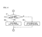
- the operation of the controller 20 will be described according to flowcharts shown in FIGS. 3 and 4 .
- the controller 20 drives the electric motor 13 and starts the engine 12 (S2).
- the controller 20 receives another operation order after one operation order is received and by the time the engine 12 is started.
- the other operation order is considered to be received.
- the other operation order is neglected.
- the controller 20 drives the electric motor 13 and starts the engine 12 (S2) based on the earliest operation order, regardless of reception of one operation order or reception of a plurality of operation orders.
- the controller 20 determines whether the plurality of operation orders are received or not (S3). When it is determined that the plurality of operation orders are not received, i.e., only one operation order is received, the controller 20 determines whether the order is an order by manipulation of the acceleration pedal 18 (S4). When it is determined that the order is the order by manipulation of the acceleration pedal 18, like the processing in step 5 of the first embodiment, the controller 20 performs clutch connection processing (S5) and transitions to the above-mentioned mode in which the engine is driven (S10).
- the controller 20 closes only the unload valves 35 and 36, switches only the oil pumps 32 and 33 to an on-load state (S8a), and transitions to the above-mentioned mode in which the engine is driven (S10).
- step 3 when it is determined that the plurality of operation orders are received, the controller 20 determines whether the order by manipulation of the cargo handling lever 17 and the order by manipulation of the handle 15 is received or not (S6).
- the controller 20 closes only the unload valves 35 and 36, switches only the oil pumps 32 and 33 to the on-load state (S8a), and transitions to the above-mentioned mode in which the engine is driven (S10) without performing the clutch connection processing.
- step 6 when it is determined that the order by manipulation of the cargo handling lever 17 and the order by manipulation of the handle 15 are received, the controller 20 acquires output from the cylinder pressure sensor 43 of the fork driving cylinder 41, and determines whether a cylinder pressure is larger than a predetermined lift pressure or not (S7).
- the cylinder pressure corresponding to a weight of cargo when the cargo is actually lifted is applied to the fork driving cylinder 41.
- the cylinder pressure due to the lift of the fork 11 or due to the lifted fork 11 is applied.
- the fork 11 is disposed at the lowermost position, the cylinder pressure is not substantially applied, regardless of whether the cargo is placed on the fork 11 or not.
- the control valve 42 for cargo handling prevents the hydraulic pressure from coming out of the fork driving cylinder 41 and maintains the cylinder pressure just before the opening of the unload valve 35 for cargo handling when the unload valve 35 for cargo handling is opened, such that the fork 11 is not lowered due to discharge of the hydraulic pressure from the fork driving cylinder 41 even when the unload valve 35 for cargo handling is opened. For this reason, by determining whether the output from the cylinder pressure sensor 43 is larger than the above-mentioned lift pressure or not, even when the unload valve 35 for cargo handling is opened, it is possible to determine whether a state in which the fork 11 is being raised or a state in which the fork 11 is disposed at the lowermost position.
- step 7 when it is determined that the cylinder pressure is larger than the lift pressure, i.e., the fork 11 is being raised, the controller 20 closes the unload valve 36 for steering, switches only the oil pump 33 for steering to the on-load state (S8b), and transitions to the above-mentioned mode in which the engine is driven (S10).
- step 7 when it is determined that the cylinder pressure is not equal to or larger than the lift pressure, i.e., the fork 11 is disposed at the lowermost position, the controller 20 closes the unload valve 35 for cargo handling, switches only the oil pump 32 for cargo handling to the on-load state (S8c), and transitions to the above-mentioned mode in which the engine is driven (S10).
- the reason for switching only the oil pump 32 for cargo handling to the on-load state and maintaining the oil pump 33 for steering in the unload state when the fork 11 is disposed at the lowermost position is that, when the fork 11 is disposed at the lowermost position, if the steering mechanism 16 is driven and the fork 11 is moved, there is a possibility that the fork 11 may be damaged.
- the engine 12 can be securely started by suppressing loads of the engine 12 and the electric motor 13 upon start of the engine.
- an appropriate cylinder can be operated according to a circumstance of the fork driving cylinder 41. That is, in the embodiment, when one operation order in the plurality of operation orders is performed, circumstances of the hydraulic actuator corresponding to each operation order are recognized, and one appropriate operation order is performed corresponding to the recognized circumstances.
- the order of priority related to the cylinders is predetermined, and only the oil pump of the cylinder having the order of high priority may switch to the on-load state with reference to the order of priority.
- the order of priority of the fork driving cylinder 41 is set to be higher than that of the steering driving cylinder 45.
- the vehicle of the embodiment is a forklift having basically the same configuration as shown in FIG. 1 .
- a hydraulic circuit 30a of the embodiment includes two pumps, i.e., a first oil pump 32a for cargo handling and a second oil pump 32b for cargo handling, which function as an oil pump for cargo handling, and unload valves 35a and 35b for cargo handling are installed at each of the oil pumps 32a and 32b.
- Ejection lines 52a and 52b are connected to the oil pumps 32a and 32b for cargo handling, respectively, which become one ejection line 52 at a downstream side thereof.
- Return lines 55a and 55b are branched from the ejection lines 52a and 52b, and the above-mentioned unload valves 35a and 35b for cargo handling are installed at the return lines 55a and 55b.
- the controller 20 drives the electric motor 13 and starts the engine 12 (S2).
- the controller 20 determines what was manipulated to cause the operation order (S4a).
- the controller 20 transitions to a mode in which an engine is driven (S10) after clutch connection processing (S5) is performed.
- step 4a when it is determined that the order is the operation order by manipulation of the handle 15, the controller 20 closes the unload valve 36 for steering, switches the oil pump 33 for steering to the on-load state (S8b), and then transitions to the mode in which the engine is driven (S10).
- step 4a when it is determined that the order is the operation order by manipulation of the cargo handling lever 17, the controller 20 acquires output from the cylinder pressure sensor 43 of the fork driving cylinder 41 and determines whether a cylinder pressure is present or not (S7).
- the controller 20 closes only a corresponding one of the first unload valve 35a for cargo handling and the second unload valve 35b for cargo handling (S8d), and then transitions to the mode in which the engine is driven (S10).
- oil from only one of the oil pumps 32a and 32b for cargo handling is sent to the fork driving cylinder 41 via the control valve 42 for cargo handling, and the fork driving cylinder 41 is driven.
- check valves 59a and 59b are installed at the ejection lines 52a and 52b, respectively, and the oil from the oil pump 32a for cargo handling corresponding to the one unload valve 35a is prevented from flowing into the oil tank 31 via the other unload valve 35b.
- step 7 when it is determined that there is no cylinder pressure, in order to switch both of the two oil pumps 32a and 32b for cargo handling to the on-load state, the controller 20 closes the first unload valve 35a for cargo handling and the second unload valve 35b for cargo handling (S8e), and then transitions to the mode in which the engine is driven (S 10).
- a number of oil pumps that switch to the on-load state is determined such that the number of oil pumps that switch to the on-load state is reduced as the cylinder pressure is increased, and the number of oil pumps switch to the on-load state.
- the embodiments of the present invention are not limited to the forklift but may be applied to any vehicle as long as the vehicle includes a hydraulic cylinder, an oil pump thereof, and a motor configured to drive the oil pump and provide a travel-driving force, for example, a shovel car or the like.
- a condition in which a brake is applied may be further added, and further, a condition in which the temperature of the engine 12 is lower than a predetermined temperature may be added.
- the present invention is applicable to an industrial vehicle such as a forklift or a shovel car, and in particular, to the case in which a hydraulic actuator is started with a small amount of manipulation and in a short amount of time from a state in which idling of a motor is stopped.
Landscapes
- Engineering & Computer Science (AREA)
- Chemical & Material Sciences (AREA)
- Combustion & Propulsion (AREA)
- Mechanical Engineering (AREA)
- General Engineering & Computer Science (AREA)
- Transportation (AREA)
- Automation & Control Theory (AREA)
- Forklifts And Lifting Vehicles (AREA)
- Control Of Vehicle Engines Or Engines For Specific Uses (AREA)
Applications Claiming Priority (2)
| Application Number | Priority Date | Filing Date | Title |
|---|---|---|---|
| JP2010234555A JP5718611B2 (ja) | 2010-10-19 | 2010-10-19 | 車両、及びその制御方法 |
| PCT/JP2011/074005 WO2012053533A1 (fr) | 2010-10-19 | 2011-10-19 | Véhicule et son procédé de commande |
Publications (3)
| Publication Number | Publication Date |
|---|---|
| EP2631456A1 true EP2631456A1 (fr) | 2013-08-28 |
| EP2631456A4 EP2631456A4 (fr) | 2018-04-18 |
| EP2631456B1 EP2631456B1 (fr) | 2020-03-04 |
Family
ID=45975244
Family Applications (1)
| Application Number | Title | Priority Date | Filing Date |
|---|---|---|---|
| EP11834372.2A Active EP2631456B1 (fr) | 2010-10-19 | 2011-10-19 | Véhicule et son procédé de commande |
Country Status (4)
| Country | Link |
|---|---|
| US (1) | US9096212B2 (fr) |
| EP (1) | EP2631456B1 (fr) |
| JP (1) | JP5718611B2 (fr) |
| WO (1) | WO2012053533A1 (fr) |
Cited By (1)
| Publication number | Priority date | Publication date | Assignee | Title |
|---|---|---|---|---|
| EP2845954A4 (fr) * | 2012-05-01 | 2016-04-06 | Hitachi Construction Machinery | Engin de chantier hybride |
Families Citing this family (2)
| Publication number | Priority date | Publication date | Assignee | Title |
|---|---|---|---|---|
| US8944449B2 (en) * | 2010-04-06 | 2015-02-03 | Polaris Industries Inc. | Side-by-side vehicle |
| CN113482897B (zh) * | 2021-06-02 | 2022-12-16 | 中国长江电力股份有限公司 | 巨型水轮发电机组调速器液压系统油泵控制装置及方法 |
Family Cites Families (14)
| Publication number | Priority date | Publication date | Assignee | Title |
|---|---|---|---|---|
| GB2251962B (en) * | 1990-11-13 | 1995-05-24 | Samsung Heavy Ind | System for automatically controlling an operation of a heavy construction |
| JPH0544517A (ja) | 1991-08-08 | 1993-02-23 | Hitachi Constr Mach Co Ltd | 作業機停止装置 |
| JP3797805B2 (ja) | 1998-09-22 | 2006-07-19 | 日立建機株式会社 | 建設機械のエンジン制御装置 |
| JP3898879B2 (ja) * | 2000-08-25 | 2007-03-28 | ジヤトコ株式会社 | 自動変速機の制御装置 |
| JP4137431B2 (ja) * | 2001-11-09 | 2008-08-20 | ナブテスコ株式会社 | 油圧回路 |
| JP3741064B2 (ja) * | 2002-03-12 | 2006-02-01 | 日産自動車株式会社 | エンジン自動停止・自動再始動装置 |
| JP4010255B2 (ja) * | 2003-02-07 | 2007-11-21 | コベルコ建機株式会社 | 建設機械の制御装置 |
| KR100926477B1 (ko) * | 2003-12-02 | 2009-11-13 | 가부시키가이샤 고마쓰 세이사쿠쇼 | 건설 기계 |
| JP2005351202A (ja) * | 2004-06-11 | 2005-12-22 | Nissan Motor Co Ltd | エンジン停止始動制御装置 |
| WO2006035589A1 (fr) * | 2004-09-27 | 2006-04-06 | Hitachi Construction Machinery Co., Ltd. | Dispositif de commande de moteur pour véhicule de chantier |
| US8607558B2 (en) * | 2007-03-29 | 2013-12-17 | Komatsu Ltd. | Work machine |
| US8573339B2 (en) * | 2008-03-27 | 2013-11-05 | Mitsubishi Nichiyu Forklift Co., Ltd. | Hybrid industrial vehicle |
| JP2010078135A (ja) * | 2008-07-17 | 2010-04-08 | Kawasaki Heavy Ind Ltd | 油圧装置及びそれを備える除雪車両 |
| JP5248377B2 (ja) * | 2009-03-16 | 2013-07-31 | 日立建機株式会社 | 作業機械の油圧駆動装置 |
-
2010
- 2010-10-19 JP JP2010234555A patent/JP5718611B2/ja active Active
-
2011
- 2011-10-19 WO PCT/JP2011/074005 patent/WO2012053533A1/fr not_active Ceased
- 2011-10-19 EP EP11834372.2A patent/EP2631456B1/fr active Active
- 2011-10-19 US US13/879,749 patent/US9096212B2/en active Active
Non-Patent Citations (1)
| Title |
|---|
| See references of WO2012053533A1 * |
Cited By (1)
| Publication number | Priority date | Publication date | Assignee | Title |
|---|---|---|---|---|
| EP2845954A4 (fr) * | 2012-05-01 | 2016-04-06 | Hitachi Construction Machinery | Engin de chantier hybride |
Also Published As
| Publication number | Publication date |
|---|---|
| US20130204500A1 (en) | 2013-08-08 |
| EP2631456B1 (fr) | 2020-03-04 |
| JP2012087669A (ja) | 2012-05-10 |
| WO2012053533A1 (fr) | 2012-04-26 |
| US9096212B2 (en) | 2015-08-04 |
| JP5718611B2 (ja) | 2015-05-13 |
| EP2631456A4 (fr) | 2018-04-18 |
Similar Documents
| Publication | Publication Date | Title |
|---|---|---|
| CN104150402B (zh) | 工业车辆和用于控制工业车辆的方法 | |
| US9631613B2 (en) | Hydraulic drive device for cargo handling vehicle | |
| EP2923995B1 (fr) | Véhicule industriel | |
| GB2251962A (en) | Temperature control of hydraulic machinery. | |
| EP2631456B1 (fr) | Véhicule et son procédé de commande | |
| EP3165496A1 (fr) | Véhicule industriel | |
| CN104944324B (zh) | 工业车辆 | |
| EP2821361B1 (fr) | Véhicule industriel | |
| JP6022616B2 (ja) | 車両、及びその制御方法 | |
| EP3178778B1 (fr) | Système hydraulique de régénération d'énergie et véhicule industriel avec ce système hydraulique | |
| CN104150407B (zh) | 工业车辆和用于控制工业车辆的方法 | |
| JP2006144820A (ja) | 産業車両の油圧制御装置及び産業車両 | |
| JP5887818B2 (ja) | 建設機械のエンジン始動制御装置 |
Legal Events
| Date | Code | Title | Description |
|---|---|---|---|
| PUAI | Public reference made under article 153(3) epc to a published international application that has entered the european phase |
Free format text: ORIGINAL CODE: 0009012 |
|
| 17P | Request for examination filed |
Effective date: 20130418 |
|
| AK | Designated contracting states |
Kind code of ref document: A1 Designated state(s): AL AT BE BG CH CY CZ DE DK EE ES FI FR GB GR HR HU IE IS IT LI LT LU LV MC MK MT NL NO PL PT RO RS SE SI SK SM TR |
|
| DAX | Request for extension of the european patent (deleted) | ||
| RA4 | Supplementary search report drawn up and despatched (corrected) |
Effective date: 20180316 |
|
| RIC1 | Information provided on ipc code assigned before grant |
Ipc: F02N 11/08 20060101ALI20180309BHEP Ipc: F02D 41/02 20060101ALI20180309BHEP Ipc: B60K 25/02 20060101ALI20180309BHEP Ipc: F02D 29/02 20060101ALI20180309BHEP Ipc: B60K 26/02 20060101ALI20180309BHEP Ipc: B60K 6/48 20071001AFI20180309BHEP Ipc: F02D 29/04 20060101ALI20180309BHEP |
|
| RIC1 | Information provided on ipc code assigned before grant |
Ipc: F02N 11/08 20060101ALI20180309BHEP Ipc: F02D 41/02 20060101ALI20180309BHEP Ipc: B60K 25/02 20060101ALI20180309BHEP Ipc: B60K 6/48 20071001AFI20180309BHEP Ipc: F02D 29/04 20060101ALI20180309BHEP Ipc: F02D 29/02 20060101ALI20180309BHEP Ipc: B60K 26/02 20060101ALI20180309BHEP |
|
| REG | Reference to a national code |
Ref country code: DE Ref legal event code: R079 Ref document number: 602011065416 Country of ref document: DE Free format text: PREVIOUS MAIN CLASS: F02D0029020000 Ipc: B60K0006480000 |
|
| GRAP | Despatch of communication of intention to grant a patent |
Free format text: ORIGINAL CODE: EPIDOSNIGR1 |
|
| STAA | Information on the status of an ep patent application or granted ep patent |
Free format text: STATUS: GRANT OF PATENT IS INTENDED |
|
| RIC1 | Information provided on ipc code assigned before grant |
Ipc: B60K 25/02 20060101ALI20190924BHEP Ipc: F02D 41/02 20060101ALI20190924BHEP Ipc: F02D 29/02 20060101ALI20190924BHEP Ipc: F02D 29/04 20060101ALI20190924BHEP Ipc: B60K 6/48 20071001AFI20190924BHEP Ipc: B60K 26/02 20060101ALI20190924BHEP Ipc: F02N 11/08 20060101ALI20190924BHEP |
|
| INTG | Intention to grant announced |
Effective date: 20191011 |
|
| RAP1 | Party data changed (applicant data changed or rights of an application transferred) |
Owner name: MITSUBISHI LOGISNEXT CO., LTD. |
|
| GRAS | Grant fee paid |
Free format text: ORIGINAL CODE: EPIDOSNIGR3 |
|
| GRAA | (expected) grant |
Free format text: ORIGINAL CODE: 0009210 |
|
| STAA | Information on the status of an ep patent application or granted ep patent |
Free format text: STATUS: THE PATENT HAS BEEN GRANTED |
|
| AK | Designated contracting states |
Kind code of ref document: B1 Designated state(s): AL AT BE BG CH CY CZ DE DK EE ES FI FR GB GR HR HU IE IS IT LI LT LU LV MC MK MT NL NO PL PT RO RS SE SI SK SM TR |
|
| REG | Reference to a national code |
Ref country code: GB Ref legal event code: FG4D |
|
| REG | Reference to a national code |
Ref country code: CH Ref legal event code: EP |
|
| REG | Reference to a national code |
Ref country code: AT Ref legal event code: REF Ref document number: 1239969 Country of ref document: AT Kind code of ref document: T Effective date: 20200315 |
|
| REG | Reference to a national code |
Ref country code: DE Ref legal event code: R096 Ref document number: 602011065416 Country of ref document: DE |
|
| REG | Reference to a national code |
Ref country code: IE Ref legal event code: FG4D |
|
| PG25 | Lapsed in a contracting state [announced via postgrant information from national office to epo] |
Ref country code: NO Free format text: LAPSE BECAUSE OF FAILURE TO SUBMIT A TRANSLATION OF THE DESCRIPTION OR TO PAY THE FEE WITHIN THE PRESCRIBED TIME-LIMIT Effective date: 20200604 Ref country code: FI Free format text: LAPSE BECAUSE OF FAILURE TO SUBMIT A TRANSLATION OF THE DESCRIPTION OR TO PAY THE FEE WITHIN THE PRESCRIBED TIME-LIMIT Effective date: 20200304 Ref country code: RS Free format text: LAPSE BECAUSE OF FAILURE TO SUBMIT A TRANSLATION OF THE DESCRIPTION OR TO PAY THE FEE WITHIN THE PRESCRIBED TIME-LIMIT Effective date: 20200304 |
|
| REG | Reference to a national code |
Ref country code: NL Ref legal event code: MP Effective date: 20200304 |
|
| PG25 | Lapsed in a contracting state [announced via postgrant information from national office to epo] |
Ref country code: GR Free format text: LAPSE BECAUSE OF FAILURE TO SUBMIT A TRANSLATION OF THE DESCRIPTION OR TO PAY THE FEE WITHIN THE PRESCRIBED TIME-LIMIT Effective date: 20200605 Ref country code: HR Free format text: LAPSE BECAUSE OF FAILURE TO SUBMIT A TRANSLATION OF THE DESCRIPTION OR TO PAY THE FEE WITHIN THE PRESCRIBED TIME-LIMIT Effective date: 20200304 Ref country code: LV Free format text: LAPSE BECAUSE OF FAILURE TO SUBMIT A TRANSLATION OF THE DESCRIPTION OR TO PAY THE FEE WITHIN THE PRESCRIBED TIME-LIMIT Effective date: 20200304 Ref country code: BG Free format text: LAPSE BECAUSE OF FAILURE TO SUBMIT A TRANSLATION OF THE DESCRIPTION OR TO PAY THE FEE WITHIN THE PRESCRIBED TIME-LIMIT Effective date: 20200604 Ref country code: SE Free format text: LAPSE BECAUSE OF FAILURE TO SUBMIT A TRANSLATION OF THE DESCRIPTION OR TO PAY THE FEE WITHIN THE PRESCRIBED TIME-LIMIT Effective date: 20200304 |
|
| REG | Reference to a national code |
Ref country code: LT Ref legal event code: MG4D |
|
| PG25 | Lapsed in a contracting state [announced via postgrant information from national office to epo] |
Ref country code: NL Free format text: LAPSE BECAUSE OF FAILURE TO SUBMIT A TRANSLATION OF THE DESCRIPTION OR TO PAY THE FEE WITHIN THE PRESCRIBED TIME-LIMIT Effective date: 20200304 |
|
| PG25 | Lapsed in a contracting state [announced via postgrant information from national office to epo] |
Ref country code: RO Free format text: LAPSE BECAUSE OF FAILURE TO SUBMIT A TRANSLATION OF THE DESCRIPTION OR TO PAY THE FEE WITHIN THE PRESCRIBED TIME-LIMIT Effective date: 20200304 Ref country code: IS Free format text: LAPSE BECAUSE OF FAILURE TO SUBMIT A TRANSLATION OF THE DESCRIPTION OR TO PAY THE FEE WITHIN THE PRESCRIBED TIME-LIMIT Effective date: 20200704 Ref country code: CZ Free format text: LAPSE BECAUSE OF FAILURE TO SUBMIT A TRANSLATION OF THE DESCRIPTION OR TO PAY THE FEE WITHIN THE PRESCRIBED TIME-LIMIT Effective date: 20200304 Ref country code: PT Free format text: LAPSE BECAUSE OF FAILURE TO SUBMIT A TRANSLATION OF THE DESCRIPTION OR TO PAY THE FEE WITHIN THE PRESCRIBED TIME-LIMIT Effective date: 20200729 Ref country code: EE Free format text: LAPSE BECAUSE OF FAILURE TO SUBMIT A TRANSLATION OF THE DESCRIPTION OR TO PAY THE FEE WITHIN THE PRESCRIBED TIME-LIMIT Effective date: 20200304 Ref country code: SM Free format text: LAPSE BECAUSE OF FAILURE TO SUBMIT A TRANSLATION OF THE DESCRIPTION OR TO PAY THE FEE WITHIN THE PRESCRIBED TIME-LIMIT Effective date: 20200304 Ref country code: LT Free format text: LAPSE BECAUSE OF FAILURE TO SUBMIT A TRANSLATION OF THE DESCRIPTION OR TO PAY THE FEE WITHIN THE PRESCRIBED TIME-LIMIT Effective date: 20200304 Ref country code: ES Free format text: LAPSE BECAUSE OF FAILURE TO SUBMIT A TRANSLATION OF THE DESCRIPTION OR TO PAY THE FEE WITHIN THE PRESCRIBED TIME-LIMIT Effective date: 20200304 Ref country code: SK Free format text: LAPSE BECAUSE OF FAILURE TO SUBMIT A TRANSLATION OF THE DESCRIPTION OR TO PAY THE FEE WITHIN THE PRESCRIBED TIME-LIMIT Effective date: 20200304 |
|
| REG | Reference to a national code |
Ref country code: AT Ref legal event code: MK05 Ref document number: 1239969 Country of ref document: AT Kind code of ref document: T Effective date: 20200304 |
|
| REG | Reference to a national code |
Ref country code: DE Ref legal event code: R097 Ref document number: 602011065416 Country of ref document: DE |
|
| PLBE | No opposition filed within time limit |
Free format text: ORIGINAL CODE: 0009261 |
|
| STAA | Information on the status of an ep patent application or granted ep patent |
Free format text: STATUS: NO OPPOSITION FILED WITHIN TIME LIMIT |
|
| PG25 | Lapsed in a contracting state [announced via postgrant information from national office to epo] |
Ref country code: DK Free format text: LAPSE BECAUSE OF FAILURE TO SUBMIT A TRANSLATION OF THE DESCRIPTION OR TO PAY THE FEE WITHIN THE PRESCRIBED TIME-LIMIT Effective date: 20200304 Ref country code: AT Free format text: LAPSE BECAUSE OF FAILURE TO SUBMIT A TRANSLATION OF THE DESCRIPTION OR TO PAY THE FEE WITHIN THE PRESCRIBED TIME-LIMIT Effective date: 20200304 |
|
| 26N | No opposition filed |
Effective date: 20201207 |
|
| PG25 | Lapsed in a contracting state [announced via postgrant information from national office to epo] |
Ref country code: PL Free format text: LAPSE BECAUSE OF FAILURE TO SUBMIT A TRANSLATION OF THE DESCRIPTION OR TO PAY THE FEE WITHIN THE PRESCRIBED TIME-LIMIT Effective date: 20200304 Ref country code: SI Free format text: LAPSE BECAUSE OF FAILURE TO SUBMIT A TRANSLATION OF THE DESCRIPTION OR TO PAY THE FEE WITHIN THE PRESCRIBED TIME-LIMIT Effective date: 20200304 |
|
| REG | Reference to a national code |
Ref country code: CH Ref legal event code: PL |
|
| PG25 | Lapsed in a contracting state [announced via postgrant information from national office to epo] |
Ref country code: LU Free format text: LAPSE BECAUSE OF NON-PAYMENT OF DUE FEES Effective date: 20201019 Ref country code: MC Free format text: LAPSE BECAUSE OF FAILURE TO SUBMIT A TRANSLATION OF THE DESCRIPTION OR TO PAY THE FEE WITHIN THE PRESCRIBED TIME-LIMIT Effective date: 20200304 |
|
| REG | Reference to a national code |
Ref country code: BE Ref legal event code: MM Effective date: 20201031 |
|
| PG25 | Lapsed in a contracting state [announced via postgrant information from national office to epo] |
Ref country code: LI Free format text: LAPSE BECAUSE OF NON-PAYMENT OF DUE FEES Effective date: 20201031 Ref country code: BE Free format text: LAPSE BECAUSE OF NON-PAYMENT OF DUE FEES Effective date: 20201031 Ref country code: CH Free format text: LAPSE BECAUSE OF NON-PAYMENT OF DUE FEES Effective date: 20201031 |
|
| PG25 | Lapsed in a contracting state [announced via postgrant information from national office to epo] |
Ref country code: IE Free format text: LAPSE BECAUSE OF NON-PAYMENT OF DUE FEES Effective date: 20201019 |
|
| PG25 | Lapsed in a contracting state [announced via postgrant information from national office to epo] |
Ref country code: TR Free format text: LAPSE BECAUSE OF FAILURE TO SUBMIT A TRANSLATION OF THE DESCRIPTION OR TO PAY THE FEE WITHIN THE PRESCRIBED TIME-LIMIT Effective date: 20200304 Ref country code: MT Free format text: LAPSE BECAUSE OF FAILURE TO SUBMIT A TRANSLATION OF THE DESCRIPTION OR TO PAY THE FEE WITHIN THE PRESCRIBED TIME-LIMIT Effective date: 20200304 Ref country code: CY Free format text: LAPSE BECAUSE OF FAILURE TO SUBMIT A TRANSLATION OF THE DESCRIPTION OR TO PAY THE FEE WITHIN THE PRESCRIBED TIME-LIMIT Effective date: 20200304 |
|
| PG25 | Lapsed in a contracting state [announced via postgrant information from national office to epo] |
Ref country code: MK Free format text: LAPSE BECAUSE OF FAILURE TO SUBMIT A TRANSLATION OF THE DESCRIPTION OR TO PAY THE FEE WITHIN THE PRESCRIBED TIME-LIMIT Effective date: 20200304 Ref country code: AL Free format text: LAPSE BECAUSE OF FAILURE TO SUBMIT A TRANSLATION OF THE DESCRIPTION OR TO PAY THE FEE WITHIN THE PRESCRIBED TIME-LIMIT Effective date: 20200304 |
|
| P01 | Opt-out of the competence of the unified patent court (upc) registered |
Effective date: 20230509 |
|
| PGFP | Annual fee paid to national office [announced via postgrant information from national office to epo] |
Ref country code: GB Payment date: 20241024 Year of fee payment: 14 |
|
| PGFP | Annual fee paid to national office [announced via postgrant information from national office to epo] |
Ref country code: FR Payment date: 20241025 Year of fee payment: 14 |
|
| PGFP | Annual fee paid to national office [announced via postgrant information from national office to epo] |
Ref country code: IT Payment date: 20241031 Year of fee payment: 14 |
|
| PGFP | Annual fee paid to national office [announced via postgrant information from national office to epo] |
Ref country code: DE Payment date: 20251028 Year of fee payment: 15 |
|
| GBPC | Gb: european patent ceased through non-payment of renewal fee |
Effective date: 20251019 |
|
| PG25 | Lapsed in a contracting state [announced via postgrant information from national office to epo] |
Ref country code: GB Free format text: LAPSE BECAUSE OF NON-PAYMENT OF DUE FEES Effective date: 20251019 |
|
| PG25 | Lapsed in a contracting state [announced via postgrant information from national office to epo] |
Ref country code: FR Free format text: LAPSE BECAUSE OF NON-PAYMENT OF DUE FEES Effective date: 20251031 |