EP2631496B1 - Commande fluidique, notamment commande pneumatique pour machines de contrôle - Google Patents
Commande fluidique, notamment commande pneumatique pour machines de contrôle Download PDFInfo
- Publication number
- EP2631496B1 EP2631496B1 EP13156354.6A EP13156354A EP2631496B1 EP 2631496 B1 EP2631496 B1 EP 2631496B1 EP 13156354 A EP13156354 A EP 13156354A EP 2631496 B1 EP2631496 B1 EP 2631496B1
- Authority
- EP
- European Patent Office
- Prior art keywords
- valve
- pressure
- fluidic
- control unit
- cylinder
- Prior art date
- Legal status (The legal status is an assumption and is not a legal conclusion. Google has not performed a legal analysis and makes no representation as to the accuracy of the status listed.)
- Active
Links
Images



Classifications
-
- F—MECHANICAL ENGINEERING; LIGHTING; HEATING; WEAPONS; BLASTING
- F15—FLUID-PRESSURE ACTUATORS; HYDRAULICS OR PNEUMATICS IN GENERAL
- F15B—SYSTEMS ACTING BY MEANS OF FLUIDS IN GENERAL; FLUID-PRESSURE ACTUATORS, e.g. SERVOMOTORS; DETAILS OF FLUID-PRESSURE SYSTEMS, NOT OTHERWISE PROVIDED FOR
- F15B20/00—Safety arrangements for fluid actuator systems; Applications of safety devices in fluid actuator systems; Emergency measures for fluid actuator systems
-
- F—MECHANICAL ENGINEERING; LIGHTING; HEATING; WEAPONS; BLASTING
- F15—FLUID-PRESSURE ACTUATORS; HYDRAULICS OR PNEUMATICS IN GENERAL
- F15B—SYSTEMS ACTING BY MEANS OF FLUIDS IN GENERAL; FLUID-PRESSURE ACTUATORS, e.g. SERVOMOTORS; DETAILS OF FLUID-PRESSURE SYSTEMS, NOT OTHERWISE PROVIDED FOR
- F15B19/00—Testing; Calibrating; Fault detection or monitoring; Simulation or modelling of fluid-pressure systems or apparatus not otherwise provided for
-
- F—MECHANICAL ENGINEERING; LIGHTING; HEATING; WEAPONS; BLASTING
- F15—FLUID-PRESSURE ACTUATORS; HYDRAULICS OR PNEUMATICS IN GENERAL
- F15B—SYSTEMS ACTING BY MEANS OF FLUIDS IN GENERAL; FLUID-PRESSURE ACTUATORS, e.g. SERVOMOTORS; DETAILS OF FLUID-PRESSURE SYSTEMS, NOT OTHERWISE PROVIDED FOR
- F15B2211/00—Circuits for servomotor systems
- F15B2211/30—Directional control
- F15B2211/305—Directional control characterised by the type of valves
- F15B2211/3052—Shuttle valves
-
- F—MECHANICAL ENGINEERING; LIGHTING; HEATING; WEAPONS; BLASTING
- F15—FLUID-PRESSURE ACTUATORS; HYDRAULICS OR PNEUMATICS IN GENERAL
- F15B—SYSTEMS ACTING BY MEANS OF FLUIDS IN GENERAL; FLUID-PRESSURE ACTUATORS, e.g. SERVOMOTORS; DETAILS OF FLUID-PRESSURE SYSTEMS, NOT OTHERWISE PROVIDED FOR
- F15B2211/00—Circuits for servomotor systems
- F15B2211/30—Directional control
- F15B2211/305—Directional control characterised by the type of valves
- F15B2211/3056—Assemblies of multiple valves
- F15B2211/30565—Assemblies of multiple valves having multiple valves for a single output member, e.g. for creating higher valve function by use of multiple valves like two 2/2-valves replacing a 5/3-valve
-
- F—MECHANICAL ENGINEERING; LIGHTING; HEATING; WEAPONS; BLASTING
- F15—FLUID-PRESSURE ACTUATORS; HYDRAULICS OR PNEUMATICS IN GENERAL
- F15B—SYSTEMS ACTING BY MEANS OF FLUIDS IN GENERAL; FLUID-PRESSURE ACTUATORS, e.g. SERVOMOTORS; DETAILS OF FLUID-PRESSURE SYSTEMS, NOT OTHERWISE PROVIDED FOR
- F15B2211/00—Circuits for servomotor systems
- F15B2211/30—Directional control
- F15B2211/32—Directional control characterised by the type of actuation
- F15B2211/329—Directional control characterised by the type of actuation actuated by fluid pressure
-
- F—MECHANICAL ENGINEERING; LIGHTING; HEATING; WEAPONS; BLASTING
- F15—FLUID-PRESSURE ACTUATORS; HYDRAULICS OR PNEUMATICS IN GENERAL
- F15B—SYSTEMS ACTING BY MEANS OF FLUIDS IN GENERAL; FLUID-PRESSURE ACTUATORS, e.g. SERVOMOTORS; DETAILS OF FLUID-PRESSURE SYSTEMS, NOT OTHERWISE PROVIDED FOR
- F15B2211/00—Circuits for servomotor systems
- F15B2211/50—Pressure control
- F15B2211/505—Pressure control characterised by the type of pressure control means
- F15B2211/50554—Pressure control characterised by the type of pressure control means the pressure control means controlling a pressure downstream of the pressure control means, e.g. pressure reducing valve
-
- F—MECHANICAL ENGINEERING; LIGHTING; HEATING; WEAPONS; BLASTING
- F15—FLUID-PRESSURE ACTUATORS; HYDRAULICS OR PNEUMATICS IN GENERAL
- F15B—SYSTEMS ACTING BY MEANS OF FLUIDS IN GENERAL; FLUID-PRESSURE ACTUATORS, e.g. SERVOMOTORS; DETAILS OF FLUID-PRESSURE SYSTEMS, NOT OTHERWISE PROVIDED FOR
- F15B2211/00—Circuits for servomotor systems
- F15B2211/50—Pressure control
- F15B2211/515—Pressure control characterised by the connections of the pressure control means in the circuit
- F15B2211/5151—Pressure control characterised by the connections of the pressure control means in the circuit being connected to a pressure source and a directional control valve
-
- F—MECHANICAL ENGINEERING; LIGHTING; HEATING; WEAPONS; BLASTING
- F15—FLUID-PRESSURE ACTUATORS; HYDRAULICS OR PNEUMATICS IN GENERAL
- F15B—SYSTEMS ACTING BY MEANS OF FLUIDS IN GENERAL; FLUID-PRESSURE ACTUATORS, e.g. SERVOMOTORS; DETAILS OF FLUID-PRESSURE SYSTEMS, NOT OTHERWISE PROVIDED FOR
- F15B2211/00—Circuits for servomotor systems
- F15B2211/70—Output members, e.g. hydraulic motors or cylinders or control therefor
- F15B2211/76—Control of force or torque of the output member
-
- F—MECHANICAL ENGINEERING; LIGHTING; HEATING; WEAPONS; BLASTING
- F15—FLUID-PRESSURE ACTUATORS; HYDRAULICS OR PNEUMATICS IN GENERAL
- F15B—SYSTEMS ACTING BY MEANS OF FLUIDS IN GENERAL; FLUID-PRESSURE ACTUATORS, e.g. SERVOMOTORS; DETAILS OF FLUID-PRESSURE SYSTEMS, NOT OTHERWISE PROVIDED FOR
- F15B2211/00—Circuits for servomotor systems
- F15B2211/80—Other types of control related to particular problems or conditions
- F15B2211/885—Control specific to the type of fluid, e.g. specific to magnetorheological fluid
- F15B2211/8855—Compressible fluids, e.g. specific to pneumatics
Definitions
- the present invention relates to a actuatable by an operator control unit, in particular as a foot control unit, the operation of a fluidic cylinder, in particular a pneumatic linear cylinder, either movable to change a degree of closure or statically durable to maintain a degree of closure allows in different modes, a control method with a valve and a corresponding fluidic cylinder and a controller, a part of which is a footswitch, in particular according to the preambles of claims 1 and 15.
- Fluidic controls for moving machine parts especially in the field of materials testing, latently pose a hazard potential.
- machines for material testing during major test series eg. B. to examine a number of similar material samples, have an accessible test room.
- Machine operation only after being released by safety sensors, such as light barriers, which measure an intervention in the test room is not a viable option for material testing machines.
- the fluid used is often air under pressure; many machines, eg. B. material testing machines and component testing machines, can be operated pneumatically.
- the DD 247 198 A5 (Patentee: Institutul de tenuum de tenuum, priority date: 15.05.1985) shows a pneumatic control for lifting tools, in which the safety function considered in the pneumatic circuit can be seen in the fact that an overpressure relief valve is arranged in front of a working cylinder.
- the individual switching functions can be selected by a mechanically actuated multi-position valve. A smooth transition from one switching function to the next does not seem to be possible.
- the implemented security functions should also be considered quite rudimentary.
- the DE 89 09 061 U1 (Applicant: Assmus, M., filing date: 26.07.1989) transports the pneumatic earlier findings to hydraulic circuits, but even a decade later, she remains in the same world of thought as herself DE 28 39 341 B2 arrested in relation to the creation of security functions.
- the DE 89 09 061 U1 proposes as an essential safety measure to arrange an additional lever on the first valve. When the lever is moved from the first valve, first the pressure flows through a shuttle valve and via another valve back to the tank.
- the GB 2 294 505 A (Applicant: Nisshinbo Industries Inc, Publication Date: 01.05.1996) presents a hydraulic circuit for a punching tool in which the ram is not allowed to run due to its inertia, even in the case of abruptly dropping pressure in a hydraulic chamber of a hydraulic cylinder takes place.
- This technical aim is to be achieved in that four ball seat check valves are connected to a servo valve in a tandem pumping system.
- the EP 2 327 884 A1 (Applicant: Caterpillar Work Tools BV, publication date: 01.06.2011) deals with a hydraulic circuit with a working piston in a cylinder-equipped hydraulic circuit that can be part of a demolition machine.
- goal of EP 2 327 884 A1 is to introduce a circuit that has a Reinforcement function in the final phase of extension of the cylinder can offer.
- an amplifier component is provided, which should be activated by a so-called "sequence valve”.
- the FIG. 1 of the EP 2 327 884 A1 In addition to your description consulted, it is an adjustable pressure relief valve that can switch the piston of a two-position valve. In none of the in the EP 2 327 884 A1 however, a two position changeover valve is disclosed.
- the US Pat. No. 5,349,151 (Patent owner: Savair Inc., Issue Date: 20.09.1994) deals with a pneumatic system whose piston, with a sufficiently high contact pressure on a resistance welding electrode, is to press this electrode onto a workpiece to be welded.
- An actuator for the welding electrode used as a cylinder in the description of US Pat. No. 5,349,151 is designated, has two pneumatically filled chambers.
- two pressure regulators will be introduced. Depending on the switching position of a valve, a different high air pressure is introduced via a line into the cylinder.
- This valve is designed as a two-position valve, which switches by a static pressure, which sets when a chamber of the cylinder has reached the selected pressure level.
- the circuit thus operates with a change between dynamic pressure and static pressure. This should make it possible to then press the welding electrode after an initial lower contact pressure with a higher contact pressure or pressure on the workpiece.
- pneumatic circuit is operated only with a classic two-position valve.
- the DE 2 158 700 A (Applicant: Festo-münfabrik Gottling Stoll, filing date: 26.11.1971) proposes to operate a control with two manual valves.
- the WO 02/058 979 A2 (Applicant: BENDIX COMMERCIAL VEHICLE SYSTEMS LLC, priority date: 04.12.200) describes another interface, namely a footswitch for actuation. Such foot switches can be obtained from many manufacturers.
- a control unit For the safe operation of a testing machine, in particular a modular material testing machine, a control unit is required, which is easy to install.
- the control should be able to be operated so that a threat to the staff, which z. B. changes a specimen in the testing machine is as low as possible, because the staff can pay full attention to the required operating handles.
- the control unit is to improve the reproducibility of educalings horren with the testing machine according to other aspects, and in particular shorten the life of the testing machine by striglings
- a valve having only two decided positions is to be regarded as a particularly advantageous valve, because it is to be regarded as particularly simple realized due to the reduced number of switching positions.
- valves with more than two positions at the corresponding points in the fluidic circuit can be used instead of the two-position valve. It is primarily a question of whether the states and switch positions described in more detail and actually found are actually to be found in a valve used. Thus, the switching positions discussed below z. B. be the two extreme positions of a valve between which are still more positions and switching positions.
- a fluidic control unit may be formed as a pneumatic control unit, the z. B. can be used on an actuated with air pressure Maschinenstoffprüfmaschine. If the material testing machine has a hydraulic system, then the fluidic control unit according to the invention can be equipped with components that are suitable for the hydraulic medium used in each case, such. As a hydraulic oil, are suitable.
- a hydraulic control unit is connectable to a hydraulic pressure source.
- a pneumatic control unit z. B. with air pressure or inert gas pressure is operable, can be connected to a compressor or a compressed gas cylinder and with a suitable pressure, for. B. a pressure of less than 200 bar, are supplied on the input side.
- Fluidic control units can be designed for a wide pressure range, in particular an input-side pressure range.
- An ingestible maximum value of a pressure is preferably with a screw z. B. in a pressure reducer, which is inserted into the fluid supply, adjustable.
- Favorable operating pressures of the controller can be calculated or extrapolated from machine parameters of materials testing machines.
- Fluidic control units can also be used for material testing machines or component testing machines. Fluidic control units are particularly suitable for testing machines, which have an actuator, preferably for the holder of a test specimen. Test specimens often have to be precisely arranged in testing machines, for which purpose the specimen is to be introduced manually or with a tool into the test area of the testing machine. The specimen is often axially aligned. Here, the holder of the specimen is to approach as accurately as possible.
- Activities on the testing machine can be carried out in particular with great care, concentration and accuracy, if the hands of the operating personnel are not claimed with routine operations on controls.
- a fluidic foot control unit With a fluidic foot control unit remain the hands of the operator, z. B. an operator, free, z. B. for service activities on a testing machine. Frequently, tests on test specimens are performed by several persons as operating personnel, one of which is the operator.
- a foot control unit has treads on each of which a signal, such as an operating signal, can be introduced into the control unit with a foot position.
- a signal such as an operating signal
- An operating signal acts as a control signal.
- a foot control unit may have a plurality of tread surfaces, each of which convert a force into a movement or a lever position.
- the force conversion takes place without electronic sensors, but can also be load cells and pressure cells, in particular as an electronic signal converter, be present in the controller and used.
- the foot control unit or a stepping field of the foot control unit is preferably in a mechanical, force-transmitting connection to an actuating element.
- An actuating position of the fluidic control unit is supplied by the actuating element at least one fluidic cylinder.
- the fluidic cylinder is preferably operatively connected to the material testing machine or constitutes part of the materials testing machine. At least one fluidic cylinder can be moved by the fluidic control unit.
- test specimens in a first and / or in a second dimension can be brought into a fixing position.
- a test specimen can be fastened at least at a first location, preferably also at a second location.
- the holder of the test piece can be detected by a fluidic control unit.
- the method and the detection represent in one view two functional states of a fluidic control unit.
- two fluidic cylinders, a first fluidic cylinder and a second fluidic cylinder are actuated by the fluidic control unit.
- a first fluidic cylinder may be associated with a first function, such as holding a first specimen
- a second fluidic cylinder may have a second function, such as the arrangement of e.g. B. a second specimen to be assigned.
- the two fluidic cylinders can clamp the two ends of a test specimen.
- Fluidic cylinders are preferably controlled independently of one another, in particular in each case with a tread field. However, it is also possible to move at least two fluidic cylinders synchronously with each other with a fluidic control unit.
- the fluidic cylinders are in particular movable bidirectionally by means of a pressure to be applied by a fluid. In this case, components of the testing machine, acting on the fluidic cylinder, such as a carriage or a jaw, to be relocated.
- the control unit offers at least two states for the operation of a fluidic cylinder.
- a first fluidic cylinder and a second fluidic cylinder can, in each case independently of one another, assume at least two states, which are predetermined by the control unit.
- the fluidic cylinder is designed to be movable for setting the respective state. By the method of a fluidic cylinder, a longitudinal extent of the fluidic cylinder is increased or decreased.
- a jogging operation is a state of the control unit in which a fluidic cylinder is movable from a first position corresponding to a first longitudinal extent to a second position corresponding to a second longitudinal extent.
- the first position and / or the second position can be extreme positions, to each of which a stop surface is assigned.
- a position is assumed which is indicated to the control unit by an operating person.
- a fluidic cylinder can be moved in one direction.
- a further state of the control of the fluidic cylinder can be moved in a direction that opposes a first direction of travel.
- a fluidic cylinder is moved in inching operation alternately in one direction, for example over a distance which is assigned to a sample holder.
- a specimen can be fitted by means of the control unit in a seat of the sample holder.
- a forward direction in a backward direction in particular in each position of the foot control, switchable.
- the forward direction may also be understood as an upward direction and the reverse direction as a downward direction.
- a direction in which the fluidic cylinder can be actuated can be adapted in particular to the design or the function of the testing machine.
- the fluidic control unit provides the fluidic cylinder with a main pressure operation.
- the fluidic cylinder is preferably supplied with a maximum ingestible pressure from the fluidic control unit.
- the maximum pressure is adjustable, but it is usually not changed in the main pressure mode.
- a clamping pressure in the fluidic cylinder can continue to build, which fixes, for example, a test specimen. A sample holder is stretched and held in this state.
- the main pressure can also be used to move the fluidic cylinder at a higher speed than would be possible in jog mode.
- the translation at the higher speed which corresponds to the main pressure
- the fluidic cylinder assumes an open position, ie the position in which no clamping pressure can be applied.
- the process of the fluidic cylinder in the main pressure mode is possible only in one direction, such as the reverse direction.
- a method in a direction opposite thereto, such as the forward direction, which may also be referred to as the closing direction, is impossible in the control unit with the higher speed corresponding to the main pressure in such a configuration and may not be inadvertent, e.g. B. by incorrect operation performed. This further increases the safety of the control and the protection of the operating operator.
- the movement of the fluidic cylinder to the retreat position causes the main pressure operation to be terminated.
- the controller is automatically prepared to start typing again. If the control unit is in a jogging mode, a change from a first to a second state, in particular into a main pressure mode, is also possible.
- the change to the main printing operation is carried out automatically by the control unit, ie, an operator or an actuated robot can cause this change only via an execution of the inching operation.
- the control unit executes automatically, preferably as a function of pressure conditions in supply lines of the control unit, when the state change takes place from the inching mode into the main pressure mode.
- An informative signaling of state changes preferably takes place acoustically.
- An audible signal such as the hissing of a valve, indicates when the jogging mode is automatically exited.
- the operator can thus understand the state of the control unit, without having to take further measures to change the state.
- the operator can leave the control unit to himself without a change of state.
- a fluidic cylinder can also be understood as an actuator unit, which comprises a hollow body and a piston or piston, which is arranged at least segmentally therein, in particular sealed therein.
- An actuator may include one or a plurality of fluidic cylinders.
- punches and hollow bodies can also deviate from a cylindrical shape in order to make favorable use of a space for the actuator unit.
- An even better seal is, however, achieved with a cylinder-like fluidic hollow body which has a curvature, that is to say a curved surface, such as a fluidic cylinder, in particular along an extension direction.
- a shape-adapted piston In the fluidic cylinder, at least in one area of the fluidic cylinder, there is a shape-adapted piston. Fluidic cylinders and pistons are components of an actuator unit.
- a first volume area of at least one second volume area is delimited by the plunger or the piston.
- the volume areas are closed and can also be referred to as chambers.
- a fluid can be introduced into the hollow body of the fluidic cylinder.
- Numerous aspects of the different Embodiments which are discussed below for fluidic cylinders and pistons may accordingly also be understood as arrangements which include punches and hollow bodies. Depending on the space used, classic fluidic cylinders or other hollow bodies with punches can be used as actuators.
- Each volume area in the fluidic cylinder is assigned a port.
- a fluid can apply a force, wherein preferably only on one side fluid is supplied, and flows from the other side fluid.
- the pressure, in particular of the supplied fluid acts on the respective side of the piston.
- a fluid pressure in the first volume range moves the piston in the direction of the second volume range, so that the second volume range decreases.
- the distribution of the fluid in the fluidic cylinder increases the first volume area of the fluidic cylinder.
- the supply of a fluid through a second connection into a second volume region of the fluidic cylinder increases the second volume region and reduces the first volume region.
- the piston moves in accordance with a pressure differential due to the pressure difference between the first volume region and the second volume region.
- the actuator can be precisely and continuously brought into a position as an actuator.
- a first valve having a plurality, at least two, positions may alternately communicate a pressure side associated with a pressure source with the first or second port of the fluidic cylinder.
- the connections for the supply of fluid are formed by pressure-resistant pipes, which preferably have a line cross-section which is greater than or equal to a flow cross-section of a connected valve.
- the connection of the valve comprising at least two positions and the one side, preferably the second side of the fluidic cylinder, which is closed off from the second side of the piston, passes through a two position changeover valve.
- the two-position changeover valve is arranged in at least one of the connections.
- the flow of fluid through this connection is interrupted.
- a second position of the two-position changeover valve an inflow of fluid from a line connection into the connection line to the first fluidic cylinder can be released.
- a fluid with a second, in particular in comparison to the pressure in the first valve higher pressure can be fed to the fluidic cylinder.
- the second pressure is also called the main pressure.
- the supply of the main pressure by means of fluid in the two-position changeover valve and further into the fluidic cylinder is by one of Connecting line upstream main pressure relief valve to two-position change valve releasable.
- the main pressure is always smaller, or at least equal or not greater, than the source pressure, which can be supplied from a fluid pressure source.
- the source pressure is also adaptable via a pressure regulating valve, so that in a control fluid pressure can be used, which corresponds to the source pressure, and - in an alternative setting of the pressure regulating valve - a fluid pressure that is smaller than the source pressure, such as an intermediate pressure, in particular less than the main pressure is.
- the flow cross-section of fluid lines should always be chosen sufficiently large in order to allow a pressure drop over the extension of the connecting line out of consideration.
- a fluid line cross section can also be used as a throttle.
- one, two or even more chokes are installed in the supply lines.
- the throttles can also be realized by fluid line cross sections.
- An isolation valve in one aspect, has a position in which a first pressure region is separated from a second pressure region of a fluid, such that pressure in the first pressure region is independent of at least one pressure change in the second pressure region, and preferably in one of the pressure regions in one Switching state, a pressure is applied, which corresponds to the atmospheric pressure of 1 bar.
- An isolation valve in the form of a two-position valve has, in addition to the unlock position, a second position, which may also be referred to as a switch-through position. In a switch-on position of an isolation valve, an input-side fluid conduit that supplies fluid to the valve is connected to an output-side fluid conduit that removes fluid from the valve for free fluid flow.
- the main pressure relief valve is preferably a two-position valve located in a supply line for fluid.
- the main pressure relief valve is still fluidly actuated.
- the fluidic actuation of the main pressure relief valve is effected by a fluid pressure which is applied to an actuating mechanism of the main pressure-free valve.
- An actuating mechanism sets at least a first or a second position of a valve, in particular without fluid from the fluidic actuation in a closed position of the valve to initiate.
- the fluidic actuation more precisely the fluid pressure for the fluidic actuation, works against a restoring force of a valve spring.
- the operating mechanism also called Unlocking mechanism may be referred to, in particular comprises a spring whose spring force is tuned to an activation point for an applied minimum pressure of a fluid.
- Unlocking mechanism also called Unlocking mechanism
- Such a two-position valve can be advantageously installed in other areas of a control unit according to the invention, because it is suitable for automatic operations.
- Actuation of the main pressure relief valve releases the main pressure for passage into the two position shuttle valve so that a fluid under main pressure enters a chamber of the fluidic cylinder and the main pressure acts on one side of the piston.
- the fluidic actuation of the main pressure relief valve may also be referred to as control pressure or back pressure.
- the control pressure can be controlled by a pilot valve.
- the pilot valve is preferably a two-position valve.
- the pilot valve is in a spring-actuated position, preferably in a switched position, which can also be referred to as a standard position.
- the actuation of the main pressure-free valve is preferably exercisable by a fluidly actuated line connection, which acts on a valve piston as the actuating mechanism of the main pressure-free valve.
- An actuation of the main pressure-free valve can also be performed automatically by a pilot valve.
- the pilot valve can interrupt the switching through a control pressure via the main pressure relief valve by the spring-actuated main pressure relief valve assumes a closed state.
- a pressure actuation so no manual or electromagnetic actuation of an isolation valve or a pilot valve.
- the operation of the pilot valve is z. B. exercisable by a fluid pressure acting on a first side of a piston or on a fluidic cylinder.
- the fluid pressure which is associated with a connection to a chamber of the fluidic cylinder, is in at least one branch of a pipeline, such as the fluid line, as the control pressure and serves in particular the connected pilot valve as a back pressure against a spring bias of the pilot valve, in particular a control piston of the pilot valve , is working.
- a fluidic control method is applied to a fluidic cylinder, so that a first position of the fluidic cylinder can be controlled to a second position of the fluidic cylinder.
- the Fluidikyzlinder can take a first or second extreme position.
- a movement of the fluidic cylinder is limited in at least one direction.
- An extreme position represents a reversal point.
- maximum adjustable pressures of a fluid can prevail in the fluidic cylinder.
- the control method guides a fluidic cylinder from a first position to a second position, wherein one of the positions may be an extreme position.
- the change of the fluidic cylinder is controlled by the inflow and outflow of a fluid from the fluidic cylinder, in particular from at least one chamber of the fluidic cylinder, in each case by at least one connection and at least one connecting line.
- the fluidic cylinder can be displaced relative to another element, such as a test receptacle, a test specimen or a piston.
- the element may be a component of a testing machine, such as a part of a sample holder.
- a testing machine such as a part of a sample holder.
- the fluidic control method comprises at least two switching states.
- Two switching states are arranged in mirror image to each other.
- the switching states have a comparable geometric arrangement, but they can qualitatively lead to a different connection, such as a directional transmission position. Alternatively, a release state can be taken in the mirror image arrangement.
- the two switching states may be present in a main pressure relief valve and an intermediate pressure relief valve.
- the intermediate pressure-free valve is a two-position valve whose positions are arranged in particular mirror images of the main pressure relief valve.
- the control unit comprises a valve, which may also be referred to as a movement valve with at least two switching states.
- Each of the switching states has a first via connection and a second through connection for a fluid, wherein the second via connection (in symbolic representation) makes an angle to the first via connection.
- the two switching states are mirror images of each other.
- the circuit diagram of the first state can be mirrored or graphically folded onto the circuit diagram of the second state. Mechanically, such graphic representations can be realized differently.
- the valve may have a straight bore in a switching state, and a bore assembly that leads from a first side of the valve body to a second side of the valve body at a displacement with respect to the first bore.
- the each of the first switching state associated terminals of the isolation valve are different on a connection side, such as the pressure input side, in particular less spaced than on the opposite terminal side, such as the pressure output side.
- the passage connections are mirrored in comparison to the first switching state on a central axis of the isolation valve.
- the first unlock state connects the first print output page, the z. B. has a connection to a connection to the first chamber of a fluidic cylinder, with a fluid supply line to the input side of the isolation valve.
- an output-side connecting line which connects a second chamber of a fluidic cylinder, released to a Fluidabloomtechnisch, z. B. opens into a fluid reservoir.
- the second unlock state has a passage connection from the fluid supply line to the connection line to the second chamber of the fluidic cylinder, wherein the connection line to the first chamber of the fluidic cylinder to a fluid discharge line z. B. leads into a fluid reservoir, which in a pneumatic implementation z. B. may be the ambient air.
- the fluid supply line is supplied via a pressure distribution with fluid from a pressure medium source.
- the main pressure relief valve and the intermediate pressure relief valve are z. B. arranged over connecting lines, so that they can complement each other in the effect.
- the main pressure-free valve and the intermediate pressure-free valve control the fluid pressure which can be supplied to the fluidic cylinder in the mirror-image switching states of the movement valve.
- Switching states can be controlled by pressure conditions in a feedback loop. With the help of a pilot valve, in particular a feedback enable can be set.
- isolation valves are actuated by a spring in a feedback release.
- a release by feedback of a fluid pressure can take place in a feedback enable.
- a first pressure region which is used during a movement of the fluidic cylinder, is assigned to an intermediate pressure region.
- a certain pressure which is in the range of the first pressure range, is applied.
- the applied after the movement in the extreme position of the fluidic cylinder intermediate pressure can be further increased.
- An increase of the movement pressure in the fluidic cylinder to a clamping pressure is without an additional (external) operation, ie by an operator, the control feasible.
- the clamping pressure to be applied can be set to a fixed value be preset.
- the clamping pressure forces the fluidic cylinder in an extreme position, which can correspond to a starting position, in particular for a movement.
- the initial position corresponds for example to a holding position of a test receptacle, which is suitable for holding a test specimen in the test receptacle and for its exact positioning.
- a starting position can also correspond to a closed position of a test receptacle in which a test specimen is firmly clamped to the test receptacle.
- the home position includes two engageable extreme positions of the fluidic cylinder.
- the starting position is a permanent position, z. B. in a retreat position, which is not automatically changed by the controller.
- a movement of the fluidic cylinder from the starting position can be achieved by actuation of the control unit z. B. done with a footswitch.
- the controller responds to the assumption of an end stop position of a fluidic cylinder.
- the end stop position may relate to an abutment surface in connection with a surface of a specimen. Only when the end stop position is reached, the operating mode of the controller in a second mode, for. B. in the main printing operation, which can also be designed as a clamping pressure operation, transferred. In the end stop position, a holding pressure can build up in the fluidic cylinder, which acts as a control pressure on a fluidic valve, which, for concern of the control pressure z. B. switches the main pressure in the fluidic cylinder.
- the usually given susceptibility, caused by special Endanschlagssensoren, switch in the response or response thereof connected valves of the pneumatic circuit, can be dispensed with by the pneumatic solution presented here.
- the pneumatic circuit is therefore in a sense endanschlagssensorenfrei executable.
- the fluidic cylinder of the fluidic control unit is connected via at least one connection for conducting a fluid.
- a further two-position valve may be arranged.
- the two-position valve is a spring-biased two-position valve.
- the spring clamping force may be counteracted by a fluid pressure, so that the two-position valve may also be referred to as a fluidically counterbalanced valve.
- a valve position by a first and a second pressure of a fluid be ingested. By the respective pressure a counter-tension, in particular against a valve spring, constructed, which holds the two-position valve in each one of the two positions.
- a first position preferably comprises a blocking position. The blocking position blocks the flow of a fluid.
- the second position of the two-position valve is in particular a switching position.
- a fluid pressure can be fed to a chamber of a fluidic cylinder.
- the position of the two-position valve can be predetermined by a fluidic countervoltage.
- a feedback for example.
- a main pressure in a second pressure range which can also be referred to as intermediate pressure range, signal pressure range or range of motion pressure, be interrupted by a closure or by a fluidic interruption.
- the two-position changeover valve of the fluidic control unit is preferably a fluidic control element that implements an alternative OR operation.
- An output-side connection can be either a first or a second connection exclusively for the supply of fluid, i. H. input side, be assigned.
- the two-position change valve z. B. may be formed as a ball seat valve.
- the valve shape of the valve corresponds to a check valve.
- the valve positions are taken by means of pressure difference between the two input-side connections. If a pressure is applied, which can also be referred to as high pressure, main pressure, clamping pressure or end-of-stroke pressure, the connection is released from the corresponding pressure side to the outlet side of the two-position changeover valve.
- the second connection which is associated with an intermediate pressure side, can be unlocked if the fluid pressure is not present in the first connection, for example because the connection line of the first connection is pressure-relieved by a two-position valve.
- the passage position of the two-position changeover valve, in particular the seat of the sealing ball on one of the input-side connections, is determined by the respectively supplied fluid pressures.
- a connection can be unlocked by the two-position changeover valve.
- a ball seat valve is a rugged valve with short switching times that reliably handles a large number of switching events. As a passive valve, it works without external operation, only as a function of the pressure differences in its connecting lines such as supply and discharge lines.
- the fluidic control unit can be further improved if a third two-position valve is installed in a line connection for fluids.
- the third two-position valve is a spring-biased two-position valve.
- the bias is, for example, by a the valve provided coil spring produced.
- the third two-position valve serves as a pilot valve. At least two positions of the valve are receivable, in which a fluid pressure in the output-side connection of the two-position valve to a downstream valve, for. B. on a two-position valve, can act.
- Two-position valves can be set very sensitively with the pilot valve.
- the pilot valve allows an exclusively fluidic actuated valve circuit can be built. Preferably, similar two-position valves are used.
- a pilot valve may act on a counterpressure side of a two position valve.
- a fluidic back pressure allows the setting of a switching state of the downstream two-position valve.
- connections can also be made from one pilot valve to two or more downstream two-position valves in order to control these in each case on a fluidic counterpressure side.
- at least one pilot valve is connected to a first and a second fluidic counter-pressure side, ie in each case on one side of downstream valves.
- a throttle on a pressure side of the pilot valve, on the z.
- the pressure side in particular the input-side line connection for switchable fluid in the pilot valve, contains a throttle between the pilot valve and a branch of this line connection.
- the branch opens into an inlet-side line connection for the fluid supply to a movement valve and in particular a fluidic cylinder.
- At a throttle occurs at least temporarily a pressure drop.
- a throttle represents a flow resistance for a fluidic connection. Due to the inhibited flow, a delayed pressure adjustment takes place on a pressure side of the pilot control valve.
- the throttle can also be referred to as a delay element.
- an adjustable throttle is used with which a delay time is adjustable.
- the delay time is determined by the time required to adjust a pressure.
- the throttle also has an influence on a pressure adjustment on the output side of the pilot valve.
- the throttle is a feedback, in particular a time constant feedback to at least one disconnect valve, adjustable.
- the first position can also be referred to as a rest position.
- the rest position is of the first valve, the z. B. is a two-position valve, ingestible. Due to the internal forces in the valve, e.g. B. via springs, the rest position is the preferred position of the valve piston.
- the retraction position is a position in which the fluidic cylinder assumes a passive position, so that the fluidic cylinder no danger, z. B. in a testing machine represents.
- an intermediate pressure holds the fluidic cylinder in an extreme position, in particular without a clamping force corresponding to the clamping pressure being exerted.
- the intermediate pressure can be supplied to the fluidic cylinder via further valve members.
- a valve member for example, is a two-position valve, with a fast pressure release can be performed, a throttle for adjusting a movement speed of the fluidic cylinder or a pressure relief valve to protect the fluidic cylinder from potentially damaging, especially seals damaging overpressures of the supplied fluid.
- a second position of the valve which includes at least two positions, is a position that may be referred to as a working position. In the working position, the valve provides a passage connection to the two position shuttle valve. The input side of the valve applied intermediate pressure is supplied to the two-position change valve.
- the two-position changeover valve directs the intermediate pressure to the fluidic cylinder.
- the fluidic cylinder begins its work, which is to apply a force to a component disposed on the cylinder, e.g. B. a testing machine such as a material testing machine, apply.
- a foot switch With the operation of the valve by a foot switch, the position of the fluidic cylinder can be changed controlled.
- a pilot valve is adjustable by supplying a fluidic pressure to the counter-pressure side of the pilot valve.
- the fluidic back pressure can be released in a feedback.
- a pressure applied to the fluidic cylinder is returned to a pressure to be applied to the fluidic cylinder.
- the connection of the pressure distribution line to the feedback can be made mechanically by a check valve. After actuation of the check valve opens this check valve, so that fluid from the pressure distribution line can flow into the feedback.
- a spring biased check valve is used which is held in a closed state by spring force.
- the pressure which can be introduced through the check valve can act on the counter-pressure side of a pilot valve, so that the pilot valve changes into a second switching state.
- the back pressure acts in particular on at least three two-position valves.
- the pilot valve can be released, so that the pressure drops on the back pressure side of two isolation valves.
- at least one unlocking valve is offset from a switching position into an unlocked position, so that z.
- a feedback of a main pressure in the fluidic cylinder can be made to an intermediate pressure in the control unit.
- the state of the fluidic control unit can be changed via a mechanical operating switch.
- the operation switch allows an intervention on the state.
- the operating switch connected to the fluidic control unit is preferably mounted tiltably.
- the storage of the control switch can also be referred to as free-floating or floating.
- By pressing z. B. with a foot of the operating switch can be spent in a first or in a second position.
- Two valves of the control unit are connected to the operating switch.
- a first valve, on which the actuation switch can engage, is in particular one of the valves with at least two positions.
- a second valve on which the actuation switch can engage is preferably a check valve. At least two valves can be operated alternately with the operating switch.
- the switching state of at least one of the valves connected to the operation switch is changed.
- the actuation takes place against a spring tension.
- At least one spring is changed during actuation such that the activating switch effects a second valve position from a first valve position, such as a blocking position.
- the mechanical actuating switch is preferably in a neutral position. In the neutral position, the spring voltages keep the actuating circuit in this position, the spring voltages do not change the position of the pistons of their valves; they are ineffective in this regard.
- the switching state of the respective valve in the neutral position is its actuation-free state, which is set only by spring force.
- a plurality of valves are interconnected by fluid line connections.
- a fluid pressure from a supply port may be supplied to a fluidic cylinder depending on fluid parameters such as compressibility or viscosity. Targeted movements of the fluidic cylinder can be caused.
- the input parameters are a mechanical force and the inlet pressure of the fluid.
- the valves present in the fluidic control unit include valves with at least two positions, such as a first movement valve and a second movement valve. At least one of the valves can be designed as a two-position valve.
- a fluidic control unit comprises a first two-position changeover valve and a second two-position changeover valve.
- first pilot valve in particular in the embodiment as a third two-position valve
- second pilot valve in particular in the embodiment as fourth two-position valve
- the other valves include a first check valve and a second check valve with which, for example, a supply of an intermediate pressure to a fluidic cylinder can be interrupted.
- a control function is made possible, in particular, by means of a first intermediate pressure free-flow valve, which can preferably be counteracted fluidically, and a second intermediate pressure free-flow valve, which can preferably be counteracted in a fluidic manner.
- the fluidic control unit may comprise a first main pressure-free valve, which is adjustable in particular with fluidic counter-voltage, and a second main pressure-free valve, which is adjustable in particular with fluidic counter-tension.
- a main pressure relief valve may also be referred to as a clamping pressure relief valve.
- the reliability is increased by the fact that the pressure is supplied to the downstream components of the fluidic control unit only in case of need.
- a first valve of each type is associated with a first fluidic cylinder.
- a first valve of each type may also be included in a first control unit and a second valve of each type in a second control unit.
- a first fluidic cylinder can, for example, fix a first test receptacle in a holding position.
- a second respective valve of each type is associated with a second fluidic cylinder.
- the second fluidic cylinder can be arranged in a second test receptacle.
- the first test receptacle and the second test receptacle can be actuated independently of each other by at least one fluidic cylinder.
- a specimen for material testing can be clamped and released for removal.
- a fluidic control advantageously comprises a footswitch and preferably a control unit.
- the fluidic control is operable on a footswitch by an operator or a robot.
- the footswitch is located near the floor. Due to the integrated in the control unit fluidic controls, the control comes without power supply. It may nevertheless be advantageous if at least one valve is designed as an electric valve. The remaining, forming a core of the circuit valves are realized without electromagnetic actuation.
- the foot switch is suitable for installation in a damp room. Penetrating liquids, such as water or hydraulic fluid, can drain out of the housing of the footswitch without interfering with the fluidic control. There is no housing seal required.
- the footswitch is preferably a tread area, such as a pedal, integrated, which is actuated by muscle power. By tapping the tread area with the foot switching positions can be taken. Switch positions are supplied to an actuator by the fluidic control.
- the actuator is preferably associated with a testing machine, in particular a sample holder of a material testing machine.
- the actuator can be used, for example, to position a sample holder.
- an actuator is a linear cylinder with a spacing between a first and a second end which is changeable, wherein the first end is preferably fixedly mounted and the second end is movable with a piston along a line.
- An actuator may exert a force on a component or a component of a testing machine. With this force, it is possible to use a component, for.
- An actuator can fix and preferably position a material sample in the material testing machine. On the positioning of the sample body or the material sample can be taken in particular manually prior to fixing, with an interaction between fluid control and handling is possible. By clamping with the aid of the actuator, the manually influenced sample body can be held exclusively by the clamping jaws in a position of the actuator.
- additional foot switches can be arranged in the control, which can be actuated in particular with a second foot.
- an actuator is assigned to only one footswitch.
- the footswitch has at least three positions.
- the foot switch acts via a mechanical connection to at least one fluidic valve.
- the fluidic valve is moved to an actuating position.
- the fluidic control comprises at least one actuation position of a fluidic valve.
- a first position of the footswitch in which the footswitch is at rest, d. H. is located without the action of an operator, is referred to as a neutral position.
- a clamping pressure may be present in the actuator.
- the actuator in the neutral position, may be in a retracted open position, which may in particular be a starting position for actuation by the controller.
- a position of the foot switch such as the second position or the third position, is ingestible against a spring force. It is advantageous if the neutral position is held by a balance of two spring forces.
- the position of the neutral position is preferably between the second and the third position of the foot switch, so that the respective position is quickly adjustable without taking the other position. Thus, the foot switch gets into a middle position when the foot switch is free of external force.
- a valve In a second position of the foot switch, a valve is actuated.
- an associated valve In the second position of the footswitch, an associated valve is either in a first state or in a second state.
- a first state of the valve corresponds to a first flow connection of a fluid and a second state of a valve can correspond to a second flow connection of the valve.
- a flow connection is assumed by the closed position of the valve.
- Via a flow connection can in the Actuator a set pressure, such as a moving pressure to be created.
- the signal pressure actuates the actuator.
- the operating position of the valve is taken with the foot switch against the force of a spring, which is associated with the valve.
- a force To take a second position of the valve, a force must be applied to the foot switch, which at least compensates for the actuating force of the spring, in particular in its effect on the valve, preferably in a first position.
- the foot switch has a third position in which a relief valve is actuated.
- a relief valve In the third position of the foot switch arranged on the foot switch return spring is compressed.
- the force to be applied against the return spring for actuating the relief valve is applied to the switch with one foot.
- the relief valve is connected to a fluidic region in which a closing pressure can be applied.
- the relief valve may also be connected to a fluid volume in which the clamping pressure is applied.
- the intermediate pressure can be relieved when the relief valve is actuated.
- the supply of the clamping pressure which can also be referred to as the main clamping pressure, is blocked by moving the relief valve into a switched-through position.
- the clamping pressure is released by discharging fluid from the actuator.
- the relief of the actuator is a state of control, in which the actuator is released from a first extreme position and preferably the second extreme position is supplied.
- the relief is associated with a fluid pressure reduction in the actuator.
- a fluid pressure in particular a main pressure, is also built up in the actuator in order to move the actuator or the fluidic cylinder into the open and safe starting position.
- the relief valve provides in one embodiment by its operation for a movement of the actuator in a position in which z. B. a jaw is no longer held in or by the actuator, in particular on a sample body. It happens automatically, d. H. without additional actuation of the foot switch, a backward movement of the actuator at maximum speed and a return of the fluidic control unit in the jogging operation.
- the fluidic control makes it possible to dwell with the foot switch between the neutral position and the second position in a transition region.
- the transition region of the actuator is movable or adjustable. If the foot switch is in the transition area, this may already cause a movement of the actuator.
- a first opening of a valve and a second opening of a passage position of the valve only partially overlap.
- the flow through a valve can be throttled.
- the actuator preferably has a first chamber and a second chamber. Both the first chamber and the second chamber, a fluid can be supplied.
- a first chamber of the actuator In a neutral position of the foot switch, a first chamber of the actuator to an intermediate pressure, which is associated with a retaining position of the actuator.
- the intermediate pressure acts on a movably mounted actuator plate.
- the direction of the force applied by the intermediate pressure on the actuator plate corresponds to the direction of a clamping force that can be applied to the actuator plate by the main pressure in the second chamber of the actuator.
- the fluidic control takes virtually automatically a retracted position when the foot switch is not actuated and the main pressure for introducing the clamping force in the actuator is not present. In this way the security is increased. At the actuator no serious mechanical bruising is added to an operator.
- a slight pressure pain can lead to a reflex-like retraction movement of the foot of the foot switch, so that the fluidic control automatically goes to the neutral position. Only when the intermediate pressure on the actuator is present beyond a reaction time predetermined by flow times at throttle components in the fluidic control, or longer lasting, is the actuator braced.
- the strained actuator is to secure the actuator position of the solidified grip or handle with the supplied by the main pressure, especially in comparison to the intermediate pressure higher, force.
- the two-position valve which takes over the function of the movement valve to control one of the fluidic cylinders, can be realized both by a two-position valve and by a three-position valve or even a four-position valve or a valve with more than four positions.
- a position may be a blocking position.
- the movement valve has a position in which only the natural leaks, z. B. the fluidic cylinder and / or the movement valve, cause or cause the movement behavior of the fluidic cylinder.
- the jog mode can be increased even further in its minimum duration to be created and thus make safer by a speed limit of the movement speed of the Piston of the fluidic cylinder is provided.
- This can be z. B. by throttling for the flow of fluid volumes to and from the fluidic realize cylinder.
- the piston of the fluidic cylinder assumes an end stop position, it can be automatically switched by means of the control from one operation to the other operation. Such a switchover is thus tamper-free. The operator can not influence that the one operation, for. B. the jogging mode, is left and that the other operation, for. B. the main printing operation is taken.
- the number of safety functions that can be integrated in the controller can be further increased if an activation valve is connected upstream of the entire controller.
- the activation valve can, for. Example, be implemented as an electromagnetic fluidic valve that releases a fluidic working pressure on all parts of the controller when both a sufficient fluid pressure is applied to the activation valve and a corresponding electrical signal, such as a potential or an electrical voltage is applied to the activation valve.
- a corresponding electrical signal such as a potential or an electrical voltage is applied to the activation valve.
- the activation valve can respond to an existing supply pressure, which must be present in order for the valve to reach a switch-over position. Otherwise, a spring pushes the activation valve in a blocking position. In the blocking position, no fluid can escape from the controller.
- the safety function will be further enhanced if there is a check valve on the working side of the controller. The non-return valve on the working side allows fluid to enter the controller. The check valve prevents leakage of the fluid present in the control via the activation valve or via the fluid pressure source.
- the activation valve can provide access to a central pressure distribution line, from which all pressures in the control unit are obtained.
- the pressure distribution line provides the highest pressure level in the control unit, which can also be referred to as source pressure.
- the activation valve of the power-free operating control unit is shut off, so that no unwanted or unpredictable movement of the fluidic cylinder, the z. B. holds a test sample by a clamping pressure can take place.
- the pressure stored in the control unit is sufficient to carry out a one-time emergency opening function of the fluidic cylinder.
- the speed of movement of all connected fluidic cylinder or sample holder can, for. B. be set to a reaction time of the operator fixed.
- z. B. a speed on the travel of 600 millimeters / minute z. B. be preset in a pneumatic drive, which is recognized as a safe movement speed.
- the movement speed of 10 mm / s is z. B. after Information and Worksheet BIA 330 216 in the BGIA Handbook for Safety at Work of the Institute for Occupational Safety and Health of the German Social Accident Insurance, Erich Schmidt Verlag & Co., Berlin 2007 , recommended for clamping workpieces.
- a fluidic control unit according to the invention can comply with such proposed speeds with less than 5% deviation. Furthermore, the clamping pressure for a secure grip on a second material can be increased in order to suppress a sliding of the actuator on the material. A lower clamping pressure can be used to prevent damage to a specimen due to clamping. The transition between movement pressure and clamping pressure is ergonomic and tamper-proof, so no additional operator is required and accidental operation can be almost eliminated. Additional hedging instruments such.
- B. Photoelectric sensors are (actually) not necessary, but may also be available to increase the reliability. The operation is without guidance and intuitively executable. Operating errors are highly unlikely.
- the function of opening with the control according to the invention from the floating pendulum bearing of the footswitch results intuitively. With the foot switch, the control unit can be quickly and safely vented, z. B. to disconnect a connection to the testing machine.
- FIG. 1 shows an embodiment of a controller 1 according to the invention, which is due to their flat design in the foot of a table or a testing machine (not shown) can be arranged or placed without affecting the access to the testing machine or z. B. to narrow an escape route.
- the controller 1 comprises the housing 74 and the bottom plate 75, wherein the housing 74 to the bottom plate 75 at least partially encloses an angle 73 of less than 50 °.
- Bottom plate 75 and housing 74 together form a fully-sided interior as in the following FIGS. 2 to 5 In the area of the housing 74 arranged ergonomically to the bottom plate 75, the first mechanical switch 51 and the second mechanical switch 52 protrude from the housing 74.
- the second mechanical switch 52 is in the neutral position 96, in which the switch 52 extends nearly parallel to the angle 73 of the housing 74.
- the mechanical switches 51, 52 can be actuated for several minutes or even hours, without this causing back pain in the operator.
- the neutral position is the first position 96 occupied by the controller 1 without an operation.
- the first mechanical switch 51 is shown in the second position 97, with the first mechanical switch 51 extending almost parallel to the bottom plate 75.
- the second position 97 is an actuating position, the z. B. by a foot (not shown) must be kept so that the first mechanical switch 51 does not automatically in a neutral position, such as the neutral position 96 of the second mechanical switch 52 passes.
- the controller 1 further includes a pressure port 78 for supplying a pressurized fluid (not shown) to the controller 1.
- a fluid pressure used inside the controller 1 is adjustable on the adjusting screw 85. The pressure is displayed on the manometer 77.
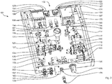
- FIG. 2 an open housing 174 of the controller 101 is shown.
- the arrangement of Components of the control unit 102 relative to the bottom plate 175 are compact.
- FIG. 5 can be removed.
- the pressure gauge 177 which indicates the adjustable with the first pressure regulating valve 120 on the adjusting screw 185, such as the working pressure of the pressure source.
- the fluid (not shown), e.g. As compressed air is fed as a pressure medium through the connector 178 to the first pressure regulating valve 120.
- the fluid may flow into the control unit 102 only when the safety valve 179 is held in an open position by an applied electric potential and a fluid pressure applied to the supply side.
- the second pressure regulating valve 121 is adjustable only with the housing 174 open, and the pressure regulating valve 121 is factory preset for safety reasons.
- the set with the second pressure regulating valve 121 pressure is applied in particular to the input of the first valve 114 and the input of the second valve 115 and is controllable as an intermediate pressure via other valves.
- the output-side pressure of the controller 101 can be supplied by the first control connection 182 and the second control connection 183 to an application, such as a first and a second sample holder.
- the first control port 182 thus at least one fluidic cylinder (not shown) can be actuated.
- the first port 182 ' is connected to the first two-position shuttle valve 112 and the second port 183' is connected to the second two-position shuttle valve 113.
- the two-position changeover valves 112, 113 are space-saving in pairs mounted on each other and screwed in particular with the bottom plate 175.
- the first pair of control terminals 182, 182 ' is controlled by the first foot switch 151.
- the second control terminal pair 183, 183 ' is controlled by the second foot switch 152.
- the foot switches 151, 152 are free-floating on the bearing 199, guided tilting.
- the mobility of the first foot switch 151 is connected to the first valve 114 via the first actuating switch 153 and to the first shut-off valve 122 via the second half of the first actuating switch 153 '.
- the first actuation switch 153 comprises a mechanical connection 155 to the first valve spring 156 of the first valve 114. Only the first foot switch 151 is shown in a position of the inching operation 187, the first one Foot switch 151 occupies a second position 197, in which the mechanical connection 155 acts on the first valve 114, thereby compressing the first valve spring 156. The actuating foot is not shown.
- the second half of the first actuating switch 153 ' is in the open position, so that the first shut-off valve 122 remains closed.
- the inching mode 187 it is set on the first valve 114 whether a fluid supply should take place via the first two-position changeover valve 112 to the first control connection 182 ', or whether a fluid pressure from the second pressure regulation valve 121 is supplied to the first control connection 182.
- the first intermediate pressure relief valve 126 is installed, so that the connection can be interrupted quickly if necessary.
- the intermediate pressure isolation valve 126 is protected against high pressures from the direction of the first control port 182, 182 'by a pressure relief valve 181.
- the intermediate pressure isolation valve 126 can be adjusted via the first pilot valve 116, which supplies the intermediate pressure isolation valve 126 with a control pressure or counterpressure required for blocking. If the control unit 102 is held in the second position 197 in the inching operation 187 with the foot switch 151, the intermediate pressure from the second pressure regulating valve 121 via the first throttle 118 and the opened first pilot valve 116 as control pressure for closing on the first intermediate pressure relief valve 126 and the Open at the first main pressure relief valve 124 build.
- the main pressure from the first pressure regulating valve 120 can be supplied to the first two-position change-over valve 112 when the first main pressure-free-closing valve 124 is open, which assumes a passage position for the main pressure to the first control connection 182 'as a result of the applied pressure.
- the first two-position changeover valve 112 may open a bypass line (not shown) of the first valve 114, so that further actuation of the first foot switch 151 in inching mode 187 has no further influence on the pressure ratios of the first control connection pair 182, 182 '.
- the first foot switch 151 In order to leave this bypass state with respect to a valve 114, 115 or the clamping state, the first foot switch 151 must be inclined to a position such as the third position 198 of the second foot switch 152. In position 198, the second foot switch 152 does not act on the second valve 115 via the second actuating switch 154, but via the second foot switch 152 second half of the second operating switch 154 'and that on the second check valve 123, which is thus opened.
- One, the second check valve 123 closing, spring force must be overcome at the second operating switch 154 '. The closing spring force helps to keep the second foot switch 152 in a neutral position without the action of an operator.
- the release of the second foot switch 152 transfers the second foot switch to the neutral position, so that again a jog operation, such as jogging operation 187, can be received via the second valve 115.
- the transition to a second state of a main pressure operation with the creation of a bypass line to the second valve 115 can now via the second throttle 119 according to the above description for the first throttle 118 after setting the intermediate pressure as the control pressure on the second intermediate pressure relief valve 127 and the second main pressure relief valve 125 automatically respectively.
- the insectsschulschulschaltventile 126, 127, the Hauptdruckfreischaltventile 124, 125 and the pilot valves 116, 117 are mounted in pairs in the compact arrangement of the control unit 102, preferably screwed.
- the back of a controller 201 is in FIG. 3 outlined.
- the connector 278 for pressure connection to the pressure source (not shown) and next to the electromechanical diverter valve 279 for uncoupling the inlet pressure from the internal pressure of the controller 201, and the adjusting screw 285 for adjusting the internal pressure, in particular the main pressure .
- the bulkhead valve 279 closes in case of power failure, ie when an applied control voltage falls below a setpoint, according to an interlock system.
- a switching position of the bulkhead valve 279 may be remotely controlled, e.g. B. via a control computer, be taken.
- first control ports 282, 282 'and the second control ports 283, 283' are shown on the backside of the housing 274, the first ports 282, 282 'serving to output fluid pressure and pressure changes of a fluid by actuating the first mechanical switch 251, and the second control ports 283, 283 'output a fluid pressure and pressure changes that are indicated to the controller 201 via the second mechanical switch 252.
- the mechanical switches 251, 252 can each be seen through an opening 276 in the bottom plate 275. If the controller 201 is standing on the ground, water entering through the opening 276, possibly from a wet shoe into the housing 275, may drain. The controller 201 operates without power, so there is no risk of electrical malfunctions, such as short circuits.
- the first mechanical switch 251 is shown in a position of the main pressure operation 286 with the first mechanical switch 251 in the neutral position 296.
- the main pressure of the fluid is output through the first port 282 '.
- the mechanical connection 255 which acts from the first mechanical switch 251 to the first valve 214, which is hidden under the bottom plate 275.
- a presetting area 292 is disposed on the bottom plate 275. The presetting area 292 allows the precise adjustment of the mechanical connection 255, tuned to the switching state of the valve 214.
- the valve 214 is displaceable in the presetting area 292 along an axis which overlaps the first mechanical switch 251.
- the spring force of the first valve 214 which acts on the first mechanical switch 251 via the mechanical connection 255, counteracts the force of the return spring 284.
- the return springs 284, 284 ' are adjustable, so that the first mechanical switch 251 and the second mechanical switch 252 are held without actuation in a floating position.
- the second mechanical switch 252 is shown pressed into a third position 298 associated with a second main pressure mode 286 '.
- the first main pressure operation 286 and the second main pressure operation 286 ' differ by an opposite effect.
- the first main pressure mode 286 is automatically assisted by the controller 201 when the first mechanical switch 251 has entered the neutral position.
- the second main pressure mode 286 ' is automatically terminated by the controller 201 when the second mechanical switch 252 assumes the neutral position.
- the first main pressure mode 286 assigns an increased fluid pressure to the first control ports 282' at the first mechanical switch 251 while the first control port 282 is switched ,
- the first mechanical switch 251 and the second mechanical switch 252 may each alternately set the control unit (not shown) in a first main pressure mode 286 or in a second main pressure mode 286 ', so that, for. B. in the controller 201 simultaneously two first main printing operations as the first main printing operation 286 are executable.
- Position 296 of the first mechanical switch 251 is clamped with the force of the main pressure, a fluidic cylinder (not shown).
- a second fluidic cylinder (not shown) is opened by the action of the main pressure.
- Position 298 can also be taken from a jogging operation for emergency opening. If, after actuation of the position 298 of the second mechanical switch 252, the latter is released into the neutral position, a transition of the controller 201 into an intermediate pressure mode takes place automatically, which moves the fluidic cylinder into a return position position.
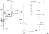
- the control unit 302 of FIG. 4 has an area of action, to which the actuator 303 belongs, and the control unit 302 has a pressure-providing area, with the activation valve 379, the check valve 330, the first pressure regulating valve 320, the second pressure regulating valve 321 and the pressure distribution line 344.
- Working pressure is supplied from a fluid pressure source 372 for the control unit 302 is provided.
- the actual control region is arranged between the effective region and the pressure supply region, in particular the two-position changeover valves 312, 313 and the movement valves 328, 329 and a plurality of two-position valves 316, 317, 322, 323, 324, 325, 326, 327 and throttles 318, 319, 331 '331' includes.
- the actuator 303 includes the first fluidic cylinder 304 and the second fluidic cylinder 310, each of which is independently operable.
- the actuator 303 is completely sensorless.
- the first state 390 is a jog operation for the first fluidic cylinder 304. A corresponding first state as the first state 390 may also be adopted in the control unit 302 for the second fluidic cylinder 310.
- the first fluidic cylinder 304 acts on the first test receptacle 332.
- the second fluidic cylinder 310 acts on the second test receptacle 333, wherein the second fluidic cylinder 310 is in the retracted position 366.
- the test receptacles can also be called actuator plates in one aspect.
- a fluidic cylinder such as the first fluidic cylinder 304, includes a piston 305 associated with a first side 308 and a second side 309. The first side 308 of the piston 305 defines the first chamber 306 and the second side 309 defines the second chamber 307.
- the first fluidic cylinder 304 is by supplying a fluid pressure through the first port 338 into the first chamber 306 or by supplying a fluid pressure through the second Port 339 in the second chamber 307, in particular alternately, operable.
- the piston 305 is movable relative to the fluidic cylinder 304.
- the position of the circle or ball in the two-position change-over valve 312 in a sealing position with respect to the first supply line 342 corresponds to the flow connection between the second supply line 343 and the second connection 341.
- the first main pressure release valve 324 in the embodiment of a two-position valve, with a control pressure against the fifth valve spring 360 can be actuated, forms the main pressure side 334 for the actuation of the first fluidic cylinder 304 through the second port 339 via the first supply line 342, which is connectable to the two-position changeover valve 312 to the second connection 341.
- the first state 390 stands Supply line 342 pressure-free through the first main pressure relief valve 324 and the intermediate pressure side 335 is active.
- the first valve 314 in the form of a two-position valve may act on the second chamber 307 by actuation of the first actuation switch 353 by means of fluid pressure.
- a jog operating pressure 380 reaches the piston 305.
- an intermediate pressure from the second pressure regulating valve 321 is passed into the first connection 340 to the first port 338 into the first chamber 306.
- fluid from the second chamber 307 is sequentially through the second port 339, the second connection 341, the first two-position changeover valve 312, the second supply line 343, the first valve 314 in the second outflow line 349 and a second muffler 347 connected derived in an environment reservoir.
- the pressure in the second chamber 307 remains constant as an increase in pressure in the first chamber 306 moves the piston 305 toward the second chamber 307.
- the position of the first valve 314 corresponds to a neutral position, which is held by the first valve spring 356.
- the first intermediate pressure release valve 326, the throttle 331 and the adjustable pressure limiter 381 are sequentially arranged.
- the pressure limiter 381 is adaptable to the pressure of the second regulating valve.
- the flow rate through the throttle 331 is adjustable, in an alternative embodiment, it can also be permanently fixed.
- a movement speed of the piston 305 is adjustable with the throttle 331. This makes the operability of the control unit 302 even more comfortable.
- the pressure limiter 381 provides additional security to protect the control unit 302 from overpressure and protection of the fluidic cylinder 304 from possible erroneous adjustment of the second pressure regulating valve 321.
- the area of the control unit 302 having a passage connection between the second pressure regulating valve 321 and a port 338, 339 is also called intermediate pressure range, which is the pressure on the Intermediate pressure side 335 corresponds, designated.
- fluid under an intermediate pressure is introduced from the second pressure regulating valve 321 via the second supply line 343 into the second chamber 307, so that the volume of the second chamber 307 increases, the volume of the first chamber 306 decreases correspondingly, and the first piston 305 moves toward the first test receptacle 332, which may be referred to as a forward direction.
- the main pressure side 334 is activated by the first Hauptlichfreischaltventil 324 from the blocking position 369 goes into the switching position 370, and the applied main pressure from the main pressure line 345 through the first supply line 342, the first two-position change valve 312 on passage in the connection 341 to the second chamber 307 switches , In this case, the second supply line 343 is closed.
- the back pressure also actuates the first intermediate pressure isolation valve 326 against the ninth valve spring 364 and switches from the closed position 370 'to the blocking position 369' of the two-position valve, the intermediate pressure-free valve 326. In this position, the first movement valve 328 can no longer effect movement of the first fluidic cylinder 304.
- a first main pressure operating state described here can only be interrupted or terminated by a further main pressure operating state, for which an actuation of the first actuation switch 353 'on the first shutoff valve 322 would be required.
- the first check valve 322 is held by the third valve spring 358 in a locking position, which, however, can pass by compression of the third valve spring 358 in the second, continuous position of the two-position lock-up valve 322.
- a working pressure or a source pressure 372 is switched through into the main pressure line 345 ', which rests through the first connection 338 in the first chamber 306 and on the first side 308 of the piston 305 acts.
- the pilot valve 316 is a two-position valve, which is a spring-actuated intermediate position for the intermediate pressure from the second pressure regulating valve 321 in a counter-pressure-actuated blocking position for the intermediate pressure goes over and in the locked position, the counter-pressure side 336 of the control unit 302 pressure-free so that the first intermediate pressure relief valve 326 by the ninth valve spring 364 and the first main pressure relief valve 324 by the fifth valve spring 360 spring-actuated occupy the position of the first state 390.
- the junction 337 is part of a feedback 350 'of the intermediate pressure from the pressure regulating valve 321 to the back pressure side 336 for automatically controlling the intermediate pressure relief valve 326 and the main pressure relief valve 324, with feedback via the variable restrictor 318 being timed.
- the second fluidic cylinder 310 can also be moved with the second movement valve 329, the adjustment speed being adjustable by the throttle 331 'and / or the time for the automatic transition to the main pressure operation with the second throttle 319.
- the first position 367 of the second valve 315 can be transferred counter to the second valve spring 357 into the working position 368 of the second valve 315, so that the second fluidic cylinder 310 is moved out of the retracted position 366.
- the second two-position changeover valve 313 can be actuated automatically by means of back pressure on the sixth valve spring 361 of the second main pressure relief valve 325 and by means of counterpressure on the tenth valve spring 365 of the second intermediate pressure isolation valve 327, corresponding to the first fluidic cylinder 304.
- a first main pressure operation is in a second main pressure operation.
- the transition from the second main pressure mode to the first main pressure mode is only possible automatically from a completed intermediate pressure mode in which the working position 368 remains held over a fixed time interval.
- the control unit 402 in FIG. 5 is in turn constructed in two parts, that is, it has the ability to operate two actuators 403, and it corresponds in many components to the structure of the control unit 302 from FIG. 4 ,
- the control unit 402 in FIG. 5 allows the actuation of the actuator 403, more specifically the actuators 403, comprising the first fluidic cylinder 404 and the second fluidic cylinder 410, the fluidic cylinders 404, 410 separated are movable from each other.
- a movement in the actuator 403 may, for. Example by means of the first valve 414 or the first stop valve 422 for the first fluidic cylinder 404 or by means of the second valve 415 or the second shut-off valve 423 for the second fluidic cylinder 410 are executed.
- the check valves 422, 423 are two-position valves. In contrast to the control unit 302 off FIG. 3 the valves 414, 415 are three-position valves. Two mirror-inverted positions of the first valve 414 in FIG. 5 form the operating positions 471, 471 ', wherein in a first operating positions 471 fluid to the first intermediate pressure free valve 426 or in another operating position 471' fluid to the first two-position change valve 412 is zuleitbar.
- the actuating positions 471, 471 ' can be found at the ends of the piston of the first valve 414 and are to be drawn in a mirror image in a circuit diagram. In the in FIG.
- the moving pressure 488 is supplied to the first fluidic cylinder 404 and the moving pressure 488 'discharged from the first fluidic cylinder 404 via the first two-position changeover valve 412 and the release state 493.
- the actuation position 471, 471 ', the activation state 493 and the activation state 493' are respectively assigned to a direction of movement of the control unit 402 to be controlled.
- a third, on a mirror axis (not shown) of the mirror image arranged operating position 471 and 471 'located position of the first valve 414 is the neutral position 496, in which all connection lines of the first valve 414 are locked, so that in this position, the first fluidic cylinder 404 at least during at least for a first phase remains motionless.
- the neutral position 496 manual actuation of the first valve 414 does not occur.
- the main pressure 495 is continuously switchable with the first check valve 422 to the first fluidic cylinder 404. Via the feedback 450, the main pressure 495 can act on the first pilot valve 416 and thus determine the feedback enable 494.
- the feedback enable circuit 494 is further carried out the feedback enable 494 "of the first main pressure relief valve 424 and in particular the termination of the feedback enable 494 'of the first intermediate pressure relief valve 426. Is used as the first pilot valve 416 two-position valve corresponding FIG.
- first throttle 418 gradually back pressure for controlling the first intermediate pressure relief valve 426 and the first Hauptlichkeschaltventils 424, these valves 424, 426 at a minimum pressure reached automatically, ie against a spring (no reference) operated ,
- a pressure-actuated first main pressure relief valve 424 of the clamping pressure 489 on the first Fluidic cylinder 404 through the first two-position change valve 412 can be applied.
- the clamping pressure 489 is variably adjustable via the first pressure regulating valve 420 with respect to the source pressure 472, which essentially corresponds to the main pressure 495, in particular for a user, and the clamping pressure 489 can be read off the pressure gauge 477. So z. B.
- the clamping pressure 489 can be fed to both the first fluidic cylinder 404 and the second fluidic cylinder 410, which is why the control unit 402, similar to the control unit 102 in FIG. 2 and the control unit 302 in FIG FIG. 4 , manages with a small number of valves, which further reduces an already very low maintenance requirements of a controller according to the invention.
- FIG. 5 It is possible to apply the first fluidic cylinder 404 through the first check valve 422 with a higher pressure, the main pressure 495, than the clamping pressure 489, which is switchable by the first main pressure relief valve 424 on the fluidic cylinder 404.
- the intermediate pressure 488, the z. B. at most 2 bar is smaller than the main pressure and smaller than the clamping pressure is from the second pressure regulating valve 421 both for the first fluidic cylinder 404 and for the second fluidic cylinder 410, z. B. by the second valve 415 and the second two-position changeover valve 413, that is provided for the entire actuator 403.
- the design options shown in the individual figures can also be interconnected in any form. All operations and movements described on a fluidic cylinder can in particular also be carried out on a second fluidic cylinder with components provided for this purpose. Components for moving a fluidic cylinder can be combined with other fluidic components to automatically control the movement of a fluidic cylinder between a retracted position and a clamping position. B. with an intermediate step, a fluidic control can be used to control a plurality of fluidic cylinders, for. B. by duplication of fluidic circuits are formed.
- the control is also versatile, because without additional sensors, the stop position of a cylinder actuated by fluidic clamping jaw on a first sample body and on a comparatively thicker second sample body is variable in a sample change ingestible.
- the use of proven mechanical components allows the integration of the controller in many different measuring constructions and a fault-resistant operation even under operating conditions that make special demands on the reliability of materials and technology.
Landscapes
- Engineering & Computer Science (AREA)
- Chemical & Material Sciences (AREA)
- Analytical Chemistry (AREA)
- Physics & Mathematics (AREA)
- Fluid Mechanics (AREA)
- Mechanical Engineering (AREA)
- General Engineering & Computer Science (AREA)
- Fluid-Pressure Circuits (AREA)
Claims (15)
- Unité de commande fluidique (102, 302, 402) avec au moins un cylindre fluidique (304, 404, 310, 410) avec laquelle au moins le cylindre fluidique (304, 404, 310, 410) peut être déplacé, cependant que l'unité de commande (102, 302, 402) offre, dans un état (390), respectivement un mode pas à pas (187) par cylindre fluidique (304, 404, 310, 410) et offre, dans un second état, un mode de pression principale (286) pour le au moins un cylindre fluidique (304, 404, 310, 410), cependant qu'un changement d'état de l'unité de commande (102, 302, 402) se fait automatiquement par un mode pas à pas (187) dans l'un des modes de pression principale (286),
caractérisé en ce
qu'une première soupape (114, 214, 314, 414, 115, 315, 415) qui comprend au moins deux positions est guidée avec un raccord (338, 339) de manière fluidique sur un côté (308, 309) d'un piston (305) du au moins un cylindre fluidique (304, 404, 310, 410) et est guidée avec un autre raccord (338, 339) de manière fluidique par une liaison (340, 341) sur un second côté (308, 309) du piston (305) du cylindre fluidique (304, 404, 310, 410), cependant qu'une soupape de commutation à deux positions (112, 312, 412, 113, 313, 413) est placée dans la liaison (340, 341) entre la première soupape (114, 214, 314, 414, 115, 315, 415) et le cylindre fluidique (304, 404, 310, 410) et qu'une soupape de déblocage de pression principale (124, 324, 424, 125, 325) qui doit être actionnée de manière fluidique est placée dans une conduite d'amenée (342) à la soupape de commutation à deux positions (112, 312, 412, 13, 313, 413), soupape de déblocage de pression principale dont l'actionnement peut être exercé de préférence par une soupape pilote (116, 316, 416, 117, 317). - Unité de commande fluidique (102, 302, 402) selon la revendication 1, caractérisée en ce qu'une autre soupape à deux positions (124, 324, 424, 125, 325, 126, 326, 426, 127, 327) est placée dans au moins une liaison (340, 341, 342) au cylindre fluidique (304, 404, 310, 410), soupape qui est une soupape à deux positions (124, 324, 424, 125, 325, 126, 326, 426, 127, 327) avec une tension fluidique antagoniste, en particulier en étant précontrainte par un ressort, qui a de préférence une position de blocage (369, 369') et une position de passage (370, 370') en fonction d'une tension fluidique antagoniste.
- Unité de commande fluidique (102, 302, 402) selon l'une des revendications précédentes, caractérisée en ce que la soupape de commutation à deux positions (112, 312, 412, 113, 313, 413) est une soupape à bille en forme de soupape anti-retour (330) qui débloque une liaison d'un côté de pression principale (334) ou d'un côté de pression intermédiaire (335) dans une chambre (306, 307) du cylindre fluidique (304, 404, 310, 410) en fonction des rapports de pression entre le côté de pression principale (334) et le côté de pression intermédiaire (335) sur la soupape de commutation à deux positions (112, 312, 412, 13, 313, 413).
- Unité de commande fluidique (102, 302, 402) selon l'une des revendications précédentes, caractérisée en ce qu'une troisième soupape à deux positions qui est une soupape à deux positions précontrainte par un ressort est guidée en tant que soupape pilote (116, 316, 416, 117, 317) sur au moins un côté de pression fluidique antagoniste (336) pour des soupapes à deux positions (124, 324, 424, 125, 325, 126, 326, 127, 327) placées en aval, en particulier de même type.
- Unité de commande fluidique (102, 302, 402) selon la revendication 4, caractérisée en ce qu'une soupape d'étranglement (118, 318, 418, 119, 319), en particulier réglable, sur un côté pression de la soupape pilote (116, 316, 416, 117, 317) a, en tant qu'élément de temporisation, une influence sur une adaptation de la pression après la soupape pilote (116, 316, 416, 117, 317).
- Unité de commande fluidique (102, 302, 402) selon l'une des revendications précédentes, caractérisée en ce que la première soupape (114, 214, 314, 414, 115, 315, 415) dans une première position, la position de repos (367), amène une pression intermédiaire (488, 488') par des éléments de soupape à une position de retrait (366) du cylindre fluidique (304, 404, 310, 410) et que de préférence la première soupape (114, 214, 314, 414, 115, 315, 415) dans une seconde position, la position de travail (368), transmet la pression intermédiaire (488) à la soupape de commutation à deux positions (112, 312, 412, 13, 313, 413).
- Unité de commande fluidique (102, 302, 402) selon l'une des revendications précédentes, caractérisée en ce qu'une rétroaction fluidique (350) est guidée vers un côté de pression fluidique antagoniste (336) de la soupape pilote (116, 316, 416, 117, 317).
- Unité de commande fluidique (102, 302, 402) selon la revendication 7, caractérisée en ce qu'une soupape de blocage devant être actionnée mécaniquement (122, 322, 422, 123, 434, 423), en particulier précontrainte par un ressort, débloque, en fonction de son actionnement, une liaison (345') d'une conduite de répartition de pression (344) dans la rétroaction (350).
- Unité de commande fluidique (102, 302, 402) selon l'une des revendications précédentes, caractérisée en ce qu'un commutateur d'actionnement mécanique (153, 153', 353, 353', 154, 154'), en particulier mobile en basculement, agit, selon un actionnement alterné à l'encontre de la précontrainte d'un ressort, sur au moins deux positions, sur deux des soupapes (114, 214, 314, 414, 122, 322, 422, 115, 315, 415, 123, 323, 423) de l'unité de commande (102, 302, 402), en particulier sur l'une des soupapes (114, 314, 414, 115, 315, 415) avec au moins deux positions et sur la soupape de blocage (122, 322, 422, 123, 323, 423), cependant qu'il existe de préférence une position neutre (96, 296, 496) du commutateur d'actionnement (153, 153', 353, 353', 154, 154') dans laquelle aucune des deux soupapes (114, 214, 314, 414, 122, 322, 422, 115, 315, 415, 123, 323, 423), ni la soupape (114, 214, 314, 414, 115, 315, 415) avec au moins deux positions, ni la soupape de blocage (122, 322, 422, 123, 323, 423), n'est dans une position d'actionnement mécanique (471).
- Unité de commande fluidique (102, 302, 402) selon l'une des revendications précédentes, caractérisée en ce que la première soupape (114, 214, 314, 414, 115, 315, 415) comme première soupape de déplacement (328) et une seconde soupape (114, 214, 314, 414, 115, 315, 415) comme seconde soupape de déplacement (329), une première soupape de commutation à deux positions (112, 312, 412, 113, 313, 413) et une seconde soupape de commutation à deux positions (112, 312, 412, 113, 313, 413), une première soupape pilote (116, 316, 416, 117, 317), en particulier dans la configuration en tant que troisième soupape à deux positions, et une seconde soupape pilote (116, 316, 416, 117, 317), en particulier dans la configuration en tant que quatrième soupape à deux positions, une première soupape de blocage (122, 322, 422, 123, 323, 423) et une seconde soupape de blocage (122, 322, 422, 123, 323, 423), une première soupape de déblocage de pression intermédiaire (126, 326, 426, 127, 327), en particulier avec une tension fluidique antagoniste, et une seconde soupape de déblocage de pression intermédiaire (126, 326, 426, 127, 327), en particulier avec une tension fluidique antagoniste, et une première soupape de déblocage de pression principale (124, 324, 424, 125, 325), en particulier avec une tension fluidique antagoniste, et une seconde soupape de déblocage de pression principale (124, 324, 424, 125, 325), en particulier avec une tension fluidique antagoniste, existent, cependant que de préférence une première soupape de chaque type et un premier cylindre fluidique (304, 404, 310, 410) sont associés respectivement à un premier adaptateur d'essai (332, 333) et qu'une seconde soupape de chaque type et un second cylindre fluidique (304, 404, 310, 410) sont associés respectivement à un second adaptateur d'essai (332, 333).
- Unité de commande fluidique (102, 302, 402) selon l'une des revendications 1 à 10, caractérisée en ce que l'unité de commande (102, 302, 402) est équipée d'au moins un commutateur au pied (51, 151, 251, 52, 152, 252) comme un commutateur à impulsion pouvant être actionné par la force musculaire, en particulier pour la commande (1, 101, 201) d'au moins un actionneur (303, 403) comme un cylindre linéaire, par exemple d'un support d'échantillon, qui comprend le cylindre fluidique (310, 410), cependant que le commutateur au pied (51, 151, 251, 52, 152, 252) présente au moins trois positions (96, 296, 496, 97, 197, 198, 298) dont au moins deux sont reliées de manière opérationnelle à une position d'actionnement d'au moins l'une des soupapes (114, 214, 314, 414, 122, 322, 422, 115, 315, 415, 123, 323, 423) et dont une première position est une position neutre (96, 296, 496) dans laquelle une pression de serrage (489) de l'actionneur (303, 403) peut être maintenue, en particulier lorsqu'un niveau de pression est atteint, cependant que dans une seconde position (97, 197) du commutateur au pied (51, 151, 251, 52, 152, 252) la force d'un ressort de la soupape à actionner (114, 314, 414, 122, 322, 422, 115, 315, 415, 123, 323, 423) qui transmet à l'actionneur (303, 403) une pression de commande qui est, de préférence, inférieure à une pression de serrage (498) est compensée et cependant que, de préférence dans la troisième position (198, 298) du commutateur au pied (51, 151, 251, 52, 152, 252) qui s'oppose à la force d'un ressort de rappel (284, 284'), une soupape de décharge (122, 322, 422, 123, 4323, 423; 114, 214, 314, 414, 115, 315, 415) comme la soupape de blocage (122, 322, 422, 123, 323, 423) peut être actionnée pour réduire une pression de fermeture (488) et/ou une pression de serrage (489).
- Unité de commande fluidique (102, 302, 402) selon la revendication 11, caractérisée en ce que, dans une plage de transition entre la seconde position (97, 197) et la troisième position (198, 298), en particulier entre la seconde position (97, 197) et la position neutre (96, 296, 496), du commutateur au pied (51, 151, 251, 52, 152, 252), un volume de fluide, peut être réglé en continu dans une chambre de fluide (304, 404, 310, 410, 306, 307) de l'actionneur (303, 403) avec la soupape (114, 214, 314, 414, 115, 315, 415), le volume de fluide est proportionnel à une position d'un composant de l'actionneur mobile au moyen de la pression du fluide.
- Unité de commande fluidique (102, 302, 402) selon la revendication 11 ou 12, caractérisée en ce qu'une première chambre (304, 404, 310, 410, 306, 307) de l'actionneur (303, 403) présente, dans la position neutre du commutateur au pied (51, 151, 251, 52, 152, 252), la pression intermédiaire (488, 488') à laquelle correspond un sens de la force sur au moins une plaque d'actionneur (332, 333) positionnée mobile qui s'oppose au sens de la force de serrage (489) qui peut être appliquée sur la plaque d'actionneur (332, 333) dans une seconde chambre (304, 404, 310, 410, 306, 307) de l'actionneur (303, 403).
- Unité de commande fluidique (102, 302, 402) selon l'une des revendications précédentes, caractérisée en ce que l'unité de commande fluidique (102, 302, 402) est une unité de commande au pied pour une machine d'essai de matériaux, cependant que de préférence l'unité de commande (102, 302, 402) a deux cylindres fluidiques (304, 404 ; 310, 410), un premier cylindre fluidique (304, 404) et un second cylindre fluidique (310, 410) qui sont déplaçables indépendamment l'un de l'autre.
- Procédé de commande fluidique, en particulier de supports d'échantillon (332, 333) d'une machine d'essai de matériaux, avec une unité de commande (102, 302, 402) selon l'une des revendications 1 à 14, qui commande avec respectivement une soupape (114, 214, 314, 414, 115, 315, 415) avec au moins deux positions (471, 496), un cylindre fluidique (304, 404, 310, 410) entre deux positions extrêmes de manière déplaçable en continu, caractérisé en ce qu'il existe, dans une soupape de déblocage de pression principale (124, 324, 424, 125, 325) et dans une soupape de déblocage de pression intermédiaire (126, 326, 426, 127, 327), un arrangement symétrique de deux états de commutation qui prennent en alternance un état de déblocage et qui peuvent être actionnés par une rétroaction (350, 350'), arrangement qui exécute une transition d'une pression de déplacement (488, 488') dans le cylindre fluidique (304, 404, 310, 410) à une tension de serrage (489) dans le cylindre fluidique (304, 404, 310, 410) par l'activation d'une rétroaction (494, 494', 494") en particulier à l'aide d'une soupape pilote (116, 316, 416, 117, 317).
Applications Claiming Priority (1)
| Application Number | Priority Date | Filing Date | Title |
|---|---|---|---|
| DE102012101459A DE102012101459A1 (de) | 2012-02-23 | 2012-02-23 | Fluidische Steuerung, insbesondere pneumatische Steuerung für Prüfmaschinen |
Publications (3)
| Publication Number | Publication Date |
|---|---|
| EP2631496A2 EP2631496A2 (fr) | 2013-08-28 |
| EP2631496A3 EP2631496A3 (fr) | 2018-03-28 |
| EP2631496B1 true EP2631496B1 (fr) | 2019-10-23 |
Family
ID=47757393
Family Applications (1)
| Application Number | Title | Priority Date | Filing Date |
|---|---|---|---|
| EP13156354.6A Active EP2631496B1 (fr) | 2012-02-23 | 2013-02-22 | Commande fluidique, notamment commande pneumatique pour machines de contrôle |
Country Status (2)
| Country | Link |
|---|---|
| EP (1) | EP2631496B1 (fr) |
| DE (1) | DE102012101459A1 (fr) |
Families Citing this family (4)
| Publication number | Priority date | Publication date | Assignee | Title |
|---|---|---|---|---|
| DE102015201993A1 (de) | 2015-02-05 | 2016-08-11 | Zwick Gmbh & Co. Kg | Materialprobenhalter mit Ansteuereinheit |
| PL3440364T3 (pl) | 2016-04-04 | 2022-03-28 | Illinois Tool Works, Inc. | Układ i sposób do badania materiałów |
| US11726018B2 (en) | 2018-11-30 | 2023-08-15 | Illinois Tool Works Inc. | Safety system interfaces and material testing systems including safety system interfaces |
| US11592375B2 (en) | 2019-03-28 | 2023-02-28 | Illinois Tool Works Inc. | Collision mitigation apparatus material testing systems having collision mitigation apparatus |
Family Cites Families (13)
| Publication number | Priority date | Publication date | Assignee | Title |
|---|---|---|---|---|
| DE2158700A1 (de) | 1971-11-26 | 1973-05-30 | Festo Maschf Stoll G | Sicherheitseinrichtung zum steuern des druckmittelzuflusses zu einer verbraucherstelle |
| DE2839341C3 (de) * | 1978-09-09 | 1981-06-19 | Daimler-Benz Ag, 7000 Stuttgart | Pneumatisches Flip-Flop |
| DD247198A5 (de) | 1985-05-17 | 1987-07-01 | Inst. De Cercetare Stiintifica Si Inginerie Techn. Pentru Ind. Constructiilor,Ro | Pneumatische steuerungs- und betaetigungsvorrichtung fuer hubsysteme |
| DE8909061U1 (de) * | 1989-07-26 | 1989-11-09 | Assmus, Manfred, 6601 Bischmisheim | Hydraulischer Sicherheitssteuerblock |
| US5349151A (en) * | 1993-02-08 | 1994-09-20 | Savair Inc. | Low impact flow control device |
| JP3609127B2 (ja) * | 1994-10-25 | 2005-01-12 | 日清紡績株式会社 | 油圧プレスのラム駆動用油圧回路 |
| DE29910803U1 (de) * | 1999-06-21 | 1999-09-16 | VAW Aluminium-Technologie GmbH, 53117 Bonn | Schaltungsanordnung zum Steuern eines Krustenbrechers |
| SE517901C2 (sv) | 2000-08-15 | 2002-07-30 | Parker Hannifin Ab | Styrsystem för pneumatiska drivanordningar |
| US6659244B2 (en) | 2000-12-04 | 2003-12-09 | Bendix Commerical Vehicle Systems Llc | Integrated foot control valve actuator |
| DE10161703B4 (de) | 2001-12-15 | 2005-02-24 | Festo Ag & Co.Kg | Entlüftungseinrichtung für einen Pneumatikantrieb |
| DE202006002727U1 (de) | 2006-02-21 | 2006-04-20 | Festo Ag & Co | Pneumatisches Antriebssystem |
| DE102007041583B4 (de) | 2007-09-01 | 2012-05-24 | Festo Ag & Co. Kg | Ventileinrichtung |
| EP2327884B1 (fr) * | 2009-11-30 | 2013-04-17 | Caterpillar Work Tools B. V. | Dispositif hydraulique pour vérins hydrauliques |
-
2012
- 2012-02-23 DE DE102012101459A patent/DE102012101459A1/de not_active Withdrawn
-
2013
- 2013-02-22 EP EP13156354.6A patent/EP2631496B1/fr active Active
Non-Patent Citations (1)
| Title |
|---|
| None * |
Also Published As
| Publication number | Publication date |
|---|---|
| DE102012101459A1 (de) | 2013-08-29 |
| EP2631496A3 (fr) | 2018-03-28 |
| EP2631496A2 (fr) | 2013-08-28 |
Similar Documents
| Publication | Publication Date | Title |
|---|---|---|
| EP2220377B1 (fr) | Mécanisme à soupape | |
| EP3056891B1 (fr) | Support d'echantillon de materiau comprenant une unite de commande | |
| EP2565469B1 (fr) | Blind rivet setting device with pressure generator | |
| EP0230529B1 (fr) | Configuration de valves pour accumulateur hydraulique | |
| DE3625222A1 (de) | Druckregler fuer hydraulisch gesteuerte werkzeugmaschinen | |
| EP1860328A1 (fr) | Dispositif de contrôle de vérin pneumatique à double effet | |
| EP2294331B1 (fr) | Dispositif de vanne hydraulique | |
| DE1576088B2 (de) | Schnellentlastungsventil fuer hydraulische kraftzylinder | |
| EP2631496A2 (fr) | Commande fluidique, notamment commande pneumatique pour machines de contrôle | |
| DD152170A5 (de) | Sicherheitsventil | |
| EP1302663A1 (fr) | Groupe moto-pompe électro-hydraulique et clapet anti-retour | |
| DE102011119784A1 (de) | Fluidbetätigte Greifvorrichtung mit Sicherheitseinrichtung | |
| DE102018200680B4 (de) | Drucküberwachungsvorrichtung und damit ausgestattete Ventilanordnung | |
| DE1295383B (de) | Sicherheitseinrichtung fuer das Steuersystem eines hydraulischen Motors mit zwei synchron zu betaetigenden Hauptventilen und einem Fuehlerventil | |
| DE4237901C2 (de) | Elektrohydraulische Steuervorrichtung und Druckminderventil | |
| DE10361619B4 (de) | Hydraulische Betätigungsvorrichtung | |
| DE3204055A1 (de) | Druckbegrenzungs- oder -regelventil | |
| DE2951232A1 (de) | Magnetventil | |
| DE102006055627A1 (de) | Kolbenbetätigtes Verriegelungsventil für ein Hydraulik-aktuatorlast-Sperrventil | |
| EP0884486A1 (fr) | Dispositif de serrage électrohydraulique | |
| DE1022870B (de) | Sicherungseinrichtung zur Verwendung in einer Anlage zur Steuerung einer stroemungsmittelbetaetigten Vorrichtung | |
| DE102006010845B4 (de) | Ventileinrichtung mit Softstartfunktion | |
| DE10161703B4 (de) | Entlüftungseinrichtung für einen Pneumatikantrieb | |
| DE202013104109U1 (de) | Hydraulikwerkzeug sowie hydraulisch betätigte Werkzeugaufnahme | |
| DE2947842C2 (de) | Hydraulische Sicherheitssteuerung mit Druckstufenregelventil |
Legal Events
| Date | Code | Title | Description |
|---|---|---|---|
| PUAI | Public reference made under article 153(3) epc to a published international application that has entered the european phase |
Free format text: ORIGINAL CODE: 0009012 |
|
| AK | Designated contracting states |
Kind code of ref document: A2 Designated state(s): AL AT BE BG CH CY CZ DE DK EE ES FI FR GB GR HR HU IE IS IT LI LT LU LV MC MK MT NL NO PL PT RO RS SE SI SK SM TR |
|
| AX | Request for extension of the european patent |
Extension state: BA ME |
|
| PUAL | Search report despatched |
Free format text: ORIGINAL CODE: 0009013 |
|
| AK | Designated contracting states |
Kind code of ref document: A3 Designated state(s): AL AT BE BG CH CY CZ DE DK EE ES FI FR GB GR HR HU IE IS IT LI LT LU LV MC MK MT NL NO PL PT RO RS SE SI SK SM TR |
|
| AX | Request for extension of the european patent |
Extension state: BA ME |
|
| RIC1 | Information provided on ipc code assigned before grant |
Ipc: F15B 20/00 20060101AFI20171220BHEP Ipc: F15B 19/00 20060101ALI20171220BHEP |
|
| PUAF | Information related to the publication of a search report (a3 document) modified or deleted |
Free format text: ORIGINAL CODE: 0009199SEPU |
|
| PUAL | Search report despatched |
Free format text: ORIGINAL CODE: 0009013 |
|
| D17D | Deferred search report published (deleted) | ||
| RIC1 | Information provided on ipc code assigned before grant |
Ipc: F15B 20/00 20060101AFI20180212BHEP Ipc: F15B 19/00 20060101ALI20180212BHEP |
|
| AK | Designated contracting states |
Kind code of ref document: A3 Designated state(s): AL AT BE BG CH CY CZ DE DK EE ES FI FR GB GR HR HU IE IS IT LI LT LU LV MC MK MT NL NO PL PT RO RS SE SI SK SM TR |
|
| AX | Request for extension of the european patent |
Extension state: BA ME |
|
| STAA | Information on the status of an ep patent application or granted ep patent |
Free format text: STATUS: REQUEST FOR EXAMINATION WAS MADE |
|
| 17P | Request for examination filed |
Effective date: 20180928 |
|
| RBV | Designated contracting states (corrected) |
Designated state(s): AL AT BE BG CH CY CZ DE DK EE ES FI FR GB GR HR HU IE IS IT LI LT LU LV MC MK MT NL NO PL PT RO RS SE SI SK SM TR |
|
| GRAP | Despatch of communication of intention to grant a patent |
Free format text: ORIGINAL CODE: EPIDOSNIGR1 |
|
| STAA | Information on the status of an ep patent application or granted ep patent |
Free format text: STATUS: GRANT OF PATENT IS INTENDED |
|
| INTG | Intention to grant announced |
Effective date: 20190322 |
|
| RAP1 | Party data changed (applicant data changed or rights of an application transferred) |
Owner name: ZWICKROELL GMBH & CO. KG |
|
| GRAJ | Information related to disapproval of communication of intention to grant by the applicant or resumption of examination proceedings by the epo deleted |
Free format text: ORIGINAL CODE: EPIDOSDIGR1 |
|
| STAA | Information on the status of an ep patent application or granted ep patent |
Free format text: STATUS: REQUEST FOR EXAMINATION WAS MADE |
|
| INTC | Intention to grant announced (deleted) | ||
| GRAR | Information related to intention to grant a patent recorded |
Free format text: ORIGINAL CODE: EPIDOSNIGR71 |
|
| GRAS | Grant fee paid |
Free format text: ORIGINAL CODE: EPIDOSNIGR3 |
|
| STAA | Information on the status of an ep patent application or granted ep patent |
Free format text: STATUS: GRANT OF PATENT IS INTENDED |
|
| GRAA | (expected) grant |
Free format text: ORIGINAL CODE: 0009210 |
|
| STAA | Information on the status of an ep patent application or granted ep patent |
Free format text: STATUS: THE PATENT HAS BEEN GRANTED |
|
| INTG | Intention to grant announced |
Effective date: 20190911 |
|
| AK | Designated contracting states |
Kind code of ref document: B1 Designated state(s): AL AT BE BG CH CY CZ DE DK EE ES FI FR GB GR HR HU IE IS IT LI LT LU LV MC MK MT NL NO PL PT RO RS SE SI SK SM TR |
|
| REG | Reference to a national code |
Ref country code: GB Ref legal event code: FG4D Free format text: NOT ENGLISH |
|
| REG | Reference to a national code |
Ref country code: CH Ref legal event code: EP |
|
| REG | Reference to a national code |
Ref country code: IE Ref legal event code: FG4D Free format text: LANGUAGE OF EP DOCUMENT: GERMAN |
|
| REG | Reference to a national code |
Ref country code: DE Ref legal event code: R096 Ref document number: 502013013789 Country of ref document: DE |
|
| REG | Reference to a national code |
Ref country code: AT Ref legal event code: REF Ref document number: 1193957 Country of ref document: AT Kind code of ref document: T Effective date: 20191115 |
|
| REG | Reference to a national code |
Ref country code: NL Ref legal event code: MP Effective date: 20191023 |
|
| REG | Reference to a national code |
Ref country code: LT Ref legal event code: MG4D |
|
| PG25 | Lapsed in a contracting state [announced via postgrant information from national office to epo] |
Ref country code: ES Free format text: LAPSE BECAUSE OF FAILURE TO SUBMIT A TRANSLATION OF THE DESCRIPTION OR TO PAY THE FEE WITHIN THE PRESCRIBED TIME-LIMIT Effective date: 20191023 Ref country code: PT Free format text: LAPSE BECAUSE OF FAILURE TO SUBMIT A TRANSLATION OF THE DESCRIPTION OR TO PAY THE FEE WITHIN THE PRESCRIBED TIME-LIMIT Effective date: 20200224 Ref country code: GR Free format text: LAPSE BECAUSE OF FAILURE TO SUBMIT A TRANSLATION OF THE DESCRIPTION OR TO PAY THE FEE WITHIN THE PRESCRIBED TIME-LIMIT Effective date: 20200124 Ref country code: PL Free format text: LAPSE BECAUSE OF FAILURE TO SUBMIT A TRANSLATION OF THE DESCRIPTION OR TO PAY THE FEE WITHIN THE PRESCRIBED TIME-LIMIT Effective date: 20191023 Ref country code: NL Free format text: LAPSE BECAUSE OF FAILURE TO SUBMIT A TRANSLATION OF THE DESCRIPTION OR TO PAY THE FEE WITHIN THE PRESCRIBED TIME-LIMIT Effective date: 20191023 Ref country code: BG Free format text: LAPSE BECAUSE OF FAILURE TO SUBMIT A TRANSLATION OF THE DESCRIPTION OR TO PAY THE FEE WITHIN THE PRESCRIBED TIME-LIMIT Effective date: 20200123 Ref country code: FI Free format text: LAPSE BECAUSE OF FAILURE TO SUBMIT A TRANSLATION OF THE DESCRIPTION OR TO PAY THE FEE WITHIN THE PRESCRIBED TIME-LIMIT Effective date: 20191023 Ref country code: LT Free format text: LAPSE BECAUSE OF FAILURE TO SUBMIT A TRANSLATION OF THE DESCRIPTION OR TO PAY THE FEE WITHIN THE PRESCRIBED TIME-LIMIT Effective date: 20191023 Ref country code: LV Free format text: LAPSE BECAUSE OF FAILURE TO SUBMIT A TRANSLATION OF THE DESCRIPTION OR TO PAY THE FEE WITHIN THE PRESCRIBED TIME-LIMIT Effective date: 20191023 Ref country code: SE Free format text: LAPSE BECAUSE OF FAILURE TO SUBMIT A TRANSLATION OF THE DESCRIPTION OR TO PAY THE FEE WITHIN THE PRESCRIBED TIME-LIMIT Effective date: 20191023 Ref country code: NO Free format text: LAPSE BECAUSE OF FAILURE TO SUBMIT A TRANSLATION OF THE DESCRIPTION OR TO PAY THE FEE WITHIN THE PRESCRIBED TIME-LIMIT Effective date: 20200123 |
|
| PG25 | Lapsed in a contracting state [announced via postgrant information from national office to epo] |
Ref country code: RS Free format text: LAPSE BECAUSE OF FAILURE TO SUBMIT A TRANSLATION OF THE DESCRIPTION OR TO PAY THE FEE WITHIN THE PRESCRIBED TIME-LIMIT Effective date: 20191023 Ref country code: HR Free format text: LAPSE BECAUSE OF FAILURE TO SUBMIT A TRANSLATION OF THE DESCRIPTION OR TO PAY THE FEE WITHIN THE PRESCRIBED TIME-LIMIT Effective date: 20191023 Ref country code: IS Free format text: LAPSE BECAUSE OF FAILURE TO SUBMIT A TRANSLATION OF THE DESCRIPTION OR TO PAY THE FEE WITHIN THE PRESCRIBED TIME-LIMIT Effective date: 20200224 |
|
| PG25 | Lapsed in a contracting state [announced via postgrant information from national office to epo] |
Ref country code: AL Free format text: LAPSE BECAUSE OF FAILURE TO SUBMIT A TRANSLATION OF THE DESCRIPTION OR TO PAY THE FEE WITHIN THE PRESCRIBED TIME-LIMIT Effective date: 20191023 |
|
| REG | Reference to a national code |
Ref country code: DE Ref legal event code: R097 Ref document number: 502013013789 Country of ref document: DE |
|
| PG2D | Information on lapse in contracting state deleted |
Ref country code: IS |
|
| PG25 | Lapsed in a contracting state [announced via postgrant information from national office to epo] |
Ref country code: RO Free format text: LAPSE BECAUSE OF FAILURE TO SUBMIT A TRANSLATION OF THE DESCRIPTION OR TO PAY THE FEE WITHIN THE PRESCRIBED TIME-LIMIT Effective date: 20191023 Ref country code: CZ Free format text: LAPSE BECAUSE OF FAILURE TO SUBMIT A TRANSLATION OF THE DESCRIPTION OR TO PAY THE FEE WITHIN THE PRESCRIBED TIME-LIMIT Effective date: 20191023 Ref country code: DK Free format text: LAPSE BECAUSE OF FAILURE TO SUBMIT A TRANSLATION OF THE DESCRIPTION OR TO PAY THE FEE WITHIN THE PRESCRIBED TIME-LIMIT Effective date: 20191023 Ref country code: EE Free format text: LAPSE BECAUSE OF FAILURE TO SUBMIT A TRANSLATION OF THE DESCRIPTION OR TO PAY THE FEE WITHIN THE PRESCRIBED TIME-LIMIT Effective date: 20191023 Ref country code: IS Free format text: LAPSE BECAUSE OF FAILURE TO SUBMIT A TRANSLATION OF THE DESCRIPTION OR TO PAY THE FEE WITHIN THE PRESCRIBED TIME-LIMIT Effective date: 20200223 |
|
| PLBE | No opposition filed within time limit |
Free format text: ORIGINAL CODE: 0009261 |
|
| STAA | Information on the status of an ep patent application or granted ep patent |
Free format text: STATUS: NO OPPOSITION FILED WITHIN TIME LIMIT |
|
| PG25 | Lapsed in a contracting state [announced via postgrant information from national office to epo] |
Ref country code: SK Free format text: LAPSE BECAUSE OF FAILURE TO SUBMIT A TRANSLATION OF THE DESCRIPTION OR TO PAY THE FEE WITHIN THE PRESCRIBED TIME-LIMIT Effective date: 20191023 Ref country code: SM Free format text: LAPSE BECAUSE OF FAILURE TO SUBMIT A TRANSLATION OF THE DESCRIPTION OR TO PAY THE FEE WITHIN THE PRESCRIBED TIME-LIMIT Effective date: 20191023 Ref country code: IT Free format text: LAPSE BECAUSE OF FAILURE TO SUBMIT A TRANSLATION OF THE DESCRIPTION OR TO PAY THE FEE WITHIN THE PRESCRIBED TIME-LIMIT Effective date: 20191023 |
|
| 26N | No opposition filed |
Effective date: 20200724 |
|
| REG | Reference to a national code |
Ref country code: CH Ref legal event code: PL |
|
| REG | Reference to a national code |
Ref country code: BE Ref legal event code: MM Effective date: 20200229 |
|
| PG25 | Lapsed in a contracting state [announced via postgrant information from national office to epo] |
Ref country code: LU Free format text: LAPSE BECAUSE OF NON-PAYMENT OF DUE FEES Effective date: 20200222 Ref country code: MC Free format text: LAPSE BECAUSE OF FAILURE TO SUBMIT A TRANSLATION OF THE DESCRIPTION OR TO PAY THE FEE WITHIN THE PRESCRIBED TIME-LIMIT Effective date: 20191023 |
|
| PG25 | Lapsed in a contracting state [announced via postgrant information from national office to epo] |
Ref country code: SI Free format text: LAPSE BECAUSE OF FAILURE TO SUBMIT A TRANSLATION OF THE DESCRIPTION OR TO PAY THE FEE WITHIN THE PRESCRIBED TIME-LIMIT Effective date: 20191023 Ref country code: CH Free format text: LAPSE BECAUSE OF NON-PAYMENT OF DUE FEES Effective date: 20200229 Ref country code: LI Free format text: LAPSE BECAUSE OF NON-PAYMENT OF DUE FEES Effective date: 20200229 |
|
| PG25 | Lapsed in a contracting state [announced via postgrant information from national office to epo] |
Ref country code: IE Free format text: LAPSE BECAUSE OF NON-PAYMENT OF DUE FEES Effective date: 20200222 |
|
| PG25 | Lapsed in a contracting state [announced via postgrant information from national office to epo] |
Ref country code: BE Free format text: LAPSE BECAUSE OF NON-PAYMENT OF DUE FEES Effective date: 20200229 |
|
| REG | Reference to a national code |
Ref country code: AT Ref legal event code: MM01 Ref document number: 1193957 Country of ref document: AT Kind code of ref document: T Effective date: 20200222 |
|
| PG25 | Lapsed in a contracting state [announced via postgrant information from national office to epo] |
Ref country code: AT Free format text: LAPSE BECAUSE OF NON-PAYMENT OF DUE FEES Effective date: 20200222 |
|
| PG25 | Lapsed in a contracting state [announced via postgrant information from national office to epo] |
Ref country code: TR Free format text: LAPSE BECAUSE OF FAILURE TO SUBMIT A TRANSLATION OF THE DESCRIPTION OR TO PAY THE FEE WITHIN THE PRESCRIBED TIME-LIMIT Effective date: 20191023 Ref country code: MT Free format text: LAPSE BECAUSE OF FAILURE TO SUBMIT A TRANSLATION OF THE DESCRIPTION OR TO PAY THE FEE WITHIN THE PRESCRIBED TIME-LIMIT Effective date: 20191023 Ref country code: CY Free format text: LAPSE BECAUSE OF FAILURE TO SUBMIT A TRANSLATION OF THE DESCRIPTION OR TO PAY THE FEE WITHIN THE PRESCRIBED TIME-LIMIT Effective date: 20191023 |
|
| PG25 | Lapsed in a contracting state [announced via postgrant information from national office to epo] |
Ref country code: MK Free format text: LAPSE BECAUSE OF FAILURE TO SUBMIT A TRANSLATION OF THE DESCRIPTION OR TO PAY THE FEE WITHIN THE PRESCRIBED TIME-LIMIT Effective date: 20191023 |
|
| PGFP | Annual fee paid to national office [announced via postgrant information from national office to epo] |
Ref country code: GB Payment date: 20260219 Year of fee payment: 14 |
|
| PGFP | Annual fee paid to national office [announced via postgrant information from national office to epo] |
Ref country code: DE Payment date: 20260121 Year of fee payment: 14 |
|
| PGFP | Annual fee paid to national office [announced via postgrant information from national office to epo] |
Ref country code: FR Payment date: 20260218 Year of fee payment: 14 |