EP2631608A2 - Encodeur - Google Patents
Encodeur Download PDFInfo
- Publication number
- EP2631608A2 EP2631608A2 EP12193527.4A EP12193527A EP2631608A2 EP 2631608 A2 EP2631608 A2 EP 2631608A2 EP 12193527 A EP12193527 A EP 12193527A EP 2631608 A2 EP2631608 A2 EP 2631608A2
- Authority
- EP
- European Patent Office
- Prior art keywords
- housing
- rotary encoder
- shaft
- encoder according
- machine part
- Prior art date
- Legal status (The legal status is an assumption and is not a legal conclusion. Google has not performed a legal analysis and makes no representation as to the accuracy of the status listed.)
- Granted
Links
Images

Classifications
-
- G—PHYSICS
- G01—MEASURING; TESTING
- G01D—MEASURING NOT SPECIALLY ADAPTED FOR A SPECIFIC VARIABLE; ARRANGEMENTS FOR MEASURING TWO OR MORE VARIABLES NOT COVERED IN A SINGLE OTHER SUBCLASS; TARIFF METERING APPARATUS; MEASURING OR TESTING NOT OTHERWISE PROVIDED FOR
- G01D5/00—Mechanical means for transferring the output of a sensing member; Means for converting the output of a sensing member to another variable where the form or nature of the sensing member does not constrain the means for converting; Transducers not specially adapted for a specific variable
- G01D5/26—Mechanical means for transferring the output of a sensing member; Means for converting the output of a sensing member to another variable where the form or nature of the sensing member does not constrain the means for converting; Transducers not specially adapted for a specific variable characterised by optical transfer means, i.e. using infrared, visible, or ultraviolet light
- G01D5/32—Mechanical means for transferring the output of a sensing member; Means for converting the output of a sensing member to another variable where the form or nature of the sensing member does not constrain the means for converting; Transducers not specially adapted for a specific variable characterised by optical transfer means, i.e. using infrared, visible, or ultraviolet light with attenuation or whole or partial obturation of beams of light
- G01D5/34—Mechanical means for transferring the output of a sensing member; Means for converting the output of a sensing member to another variable where the form or nature of the sensing member does not constrain the means for converting; Transducers not specially adapted for a specific variable characterised by optical transfer means, i.e. using infrared, visible, or ultraviolet light with attenuation or whole or partial obturation of beams of light the beams of light being detected by photocells
- G01D5/347—Mechanical means for transferring the output of a sensing member; Means for converting the output of a sensing member to another variable where the form or nature of the sensing member does not constrain the means for converting; Transducers not specially adapted for a specific variable characterised by optical transfer means, i.e. using infrared, visible, or ultraviolet light with attenuation or whole or partial obturation of beams of light the beams of light being detected by photocells using displacement encoding scales
- G01D5/3473—Circular or rotary encoders
-
- G—PHYSICS
- G01—MEASURING; TESTING
- G01D—MEASURING NOT SPECIALLY ADAPTED FOR A SPECIFIC VARIABLE; ARRANGEMENTS FOR MEASURING TWO OR MORE VARIABLES NOT COVERED IN A SINGLE OTHER SUBCLASS; TARIFF METERING APPARATUS; MEASURING OR TESTING NOT OTHERWISE PROVIDED FOR
- G01D11/00—Component parts of measuring arrangements not specially adapted for a specific variable
- G01D11/24—Housings ; Casings for instruments
- G01D11/245—Housings for sensors
Definitions
- the invention relates to a rotary encoder with a housing according to claim 1.
- Rotary encoders are used to measure rotational movements of a rotatably mounted body, in particular a shaft, over one or more revolutions. The rotational movement is detected incrementally or absolutely. In conjunction with gear racks and gear wheels or with threaded spindles, linear movements can also be measured with a rotary encoder.
- Rotary encoders are used in large numbers as so-called motor-feed-back devices and serve in this application to form position or angle information, which are used for the commutation of electric drives.
- synchronous motors require information about the absolute rotor position immediately after switching on the supply voltage.
- the rotary encoders with additional commutation signals - they provide relatively coarse position information - and the absolute rotary encoders in single or multiturn design, which immediately output the exact angular position with accuracy of just a few seconds.
- Such encoders are often produced and installed in large quantities. It is all the more important that these devices are economical to manufacture and easy to assemble, for example on electric motors.
- the invention has for its object to provide a rotary encoder of the type mentioned, which can be produced and assembled by simple means and by a comparatively high measurement accuracy can be achieved.
- the rotary encoder comprises a housing and a shaft having a (longitudinal) axis. At this shaft a part disc is fixed against rotation.
- the shaft is formed, in particular by precisely manufactured stop surfaces, for positionally accurate attachment to a first machine part.
- a scanning device for scanning the indexing disk is also set.
- the housing is designed so that an outer surface or stop surface forms a positionally accurate radial stop in the radial direction to a second machine part.
- the housing further comprises a housing body and a lid, wherein the housing body and the lid are connected to each other by a press-fitting and the housing has a mechanically resilient element which is deformed as a result of the press-fitting.
- the indexing disk can carry an incremental or absolute coding, wherein the sampling can be based in particular on an inductive measuring principle.
- the press-fitting is vorOSEbar under relative movement of the cover to the housing body in a direction parallel to the axis.
- the press fitting according to be designed a longitudinal compression bandage, so that therefore the lid is pressed under axial force in the housing body.
- the lid is pressed to limit the axial movement at the end of the joining operation against a shoulder in the housing body.
- the resilient element is integrally formed on the housing body.
- the compliant element may be an integral part of the one-piece housing body.
- the element may be machined out of the wall of the housing body by machining.
- the compliant element is then made of the same material as the housing body.
- an aluminum alloy can be chosen with advantage as material.
- the housing may have a plurality of elements which are arranged offset in the circumferential direction.
- the element is configured as a circumferential circumferential web.
- the web may optionally be interrupted, so that there is a web with several interruptions or more webs.
- the rotary encoder can be designed so that the element is deformed as a result of the press-fitting in the axial direction and / or in the radial direction.
- the element may be plastically deformed as a result of the press-fitting.
- the construction according to the invention is particularly advantageous when the rotary encoder is designed bearingless.
- the first and second machine parts are naturally arranged rotatably to each other.
- the rotary encoder can advantageously be designed so that the shaft is rigidly fixed to the first machine part and the housing of the rotary encoder fixed to the second machine part.
- the shaft for positionally accurate mounting on a first machine part is formed with a conical surface.
- the rotary encoder comprises a housing 1 and a shaft 2, which has a longitudinal axis or axis A.
- the housing 1 has a comparatively solid and rigid housing body 1.1.
- the first Approximation has a cylindrical outer contour with respect to the axis A and is made in the illustrated embodiment of an aluminum material.
- An eccentrically rotatable clamping bolt 1.14 is arranged on the housing body 1.1.
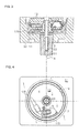
- the housing body 1.1 in a region with a comparatively thick-walled cross section has a precisely produced outer surface 1.13 (see FIG FIGS. 3, 4 ).
- the respective outer surface 1.13 may deviate only from an undersized dimension of 0.03 mm and an oversize of 0.02 mm from the specified external dimension (here 64.97 mm).
- a scanning device 1.11 is furthermore fixed or fixed on the inside.
- the rotary encoder is based on an inductive measuring principle.
- the scanner 1.11 configured as a circuit board with transmitter and receiver tracks, which also electronic components are mounted on the circuit board for the operation of the transmission conductor tracks and signal processing.
- On the circuit board is still a connector 1.15 mounted for making a plug connection to a cable, which serves to power the encoder and signal transmission to a subsequent electronics.
- the housing body 1.1 has a substantially hollow-cylindrical contour inside.
- two circumferential grooves are machined, so that a circumferential thin web 1.12 is formed.
- the web 1.12 serves as a compliant element as described below. Thereafter, the inner surfaces are processed on both sides of the grooves as far as in this area inside a diameter ⁇ D is present.
- the inner surface of the web 1.12 protrudes into the substantially hollow cylindrical space of the housing body 1.1 with the supernatant ⁇ (see FIG. 2a ).
- the rotary encoder also includes the shaft 2, which is centrally inserted into the housing body 1.1 and to which a part disc 2.1 is fixed against rotation.
- This consists of a substrate, which is made of epoxy resin in the illustrated embodiment, and on which two graduation tracks are arranged.
- the dividing disk 2.1 is in the intended Operation of the encoder is rotatable about the axis A and is scanned inductively in the example shown by the scanning device 1.11.
- the division tracks are circular and arranged with respect to the axis A concentric with different diameters on the substrate.
- the two graduation tracks each consist of a periodic sequence of alternately arranged electrically conductive graduation regions and nonconductive graduation regions. As a material for the electrically conductive portions of copper was applied to the substrate in the example shown. By contrast, the substrate was not coated in the nonconductive graduation regions.
- the shaft 2 has a precisely manufactured outer surface 2.2.
- the outer surface 2.2 is configured conical.
- the shaft 2 is not mounted on the housing 1, so here is a bearingless encoder before.
- the housing 1 comprises a cover 1.2. In the illustrated embodiment, this is designed cap-shaped and can be inserted into the interior of the housing body 1.1.
- the lid 1.2 has a substantially cylindrical outer surface, so that can be regarded as the circumferential outer surface as a lateral surface of a cylinder.
- the maximum outer diameter of the outer surface is less than or equal to the above-described inner diameter ⁇ D of the housing body 1.1 in the corresponding insertion region. Accordingly, when the cover 1.2 and the housing body 1.1 are assembled, the cover 1.2 is initially inserted virtually without force until the outer surface of the cover 1.2 reaches the web 1.12 under axial advancing movement, which protrudes into the housing body 1.1 with the radial projection ⁇ .
- the cover 1.2 Upon further axial movement of the cover 1.2 relative to the housing body 1.1, the resilient circumferential web is deformed until 12.12 finally 1.2 is present at a shoulder of the housing body 1.1 and the web 1.12 according to the FIG. 2b is plastically deformed.
- the cover 1.2 is thus connected by means of press-fitting, here in the sense of a longitudinal compression bandage, with the housing body 1.1.
- the outer surface 1.13 forms a positionally rigid in the radial direction rigid stop on a second machine part 3.2.
- the wall thickness of the housing body 1.1 is greater than in the cross-section in which the elastic element 1.12 is arranged. Due to the flexibility of the web 1.12, no change in the outer dimensions in the area of the outer surfaces 1.13 of the housing body 1.1 can be seen, although accuracies in the range of 1/100 mm are required here.
- the rotary encoder is used to generate commutation signals for an electric motor, to which the encoder can be clamped.
- the electric motor has according to the FIG. 3 a motor shaft as the first machine part 3.1 and a stator housing as the second machine part 3.2.
- the first machine part 3.1 is arranged rotatable relative to the second machine part 3.2.
- the designed as a motor shaft first machine part 3.1 has an internal thread and a conical bore.
- the second machine part 3.2 has a hollow cylindrical recess. Both this recess and the conical bore must be made extremely precise.
- the shaft 2 on the first machine part 3.1 (motor shaft) is first fixed in a rotationally fixed and accurate position by means of a central screw 2.3. Thereafter, the eccentric clamping bolt is operated 1.14, so that the outer surfaces of the housing 1 1.13 are urged against the wall of the recess in the second machine part (stator housing). Due to the extremely low tolerances hardly any shifts are noticeable here. The housing 1 and thus also the scanning device 1.11 is thus accurately mounted on the second machine part 3.2. It should also be noted here that the rotary encoder does not have a compensating coupling, which is often used to compensate for an offset between the shaft 2 and the first machine part 3.1 elastic. Here can be dispensed with such a compensation coupling.
Landscapes
- Physics & Mathematics (AREA)
- General Physics & Mathematics (AREA)
- Transmission And Conversion Of Sensor Element Output (AREA)
Applications Claiming Priority (1)
| Application Number | Priority Date | Filing Date | Title |
|---|---|---|---|
| DE102012202683A DE102012202683A1 (de) | 2012-02-22 | 2012-02-22 | Drehgeber |
Publications (3)
| Publication Number | Publication Date |
|---|---|
| EP2631608A2 true EP2631608A2 (fr) | 2013-08-28 |
| EP2631608A3 EP2631608A3 (fr) | 2015-09-02 |
| EP2631608B1 EP2631608B1 (fr) | 2016-10-19 |
Family
ID=47227635
Family Applications (1)
| Application Number | Title | Priority Date | Filing Date |
|---|---|---|---|
| EP12193527.4A Active EP2631608B1 (fr) | 2012-02-22 | 2012-11-21 | Encodeur |
Country Status (5)
| Country | Link |
|---|---|
| US (1) | US9012831B2 (fr) |
| EP (1) | EP2631608B1 (fr) |
| JP (1) | JP6246471B2 (fr) |
| CN (1) | CN103292828B (fr) |
| DE (1) | DE102012202683A1 (fr) |
Families Citing this family (8)
| Publication number | Priority date | Publication date | Assignee | Title |
|---|---|---|---|---|
| JP2596625B2 (ja) | 1990-03-08 | 1997-04-02 | 株式会社日立ビルシステムサービス | 群管理エレベータの呼び登録装置 |
| ES2912101T3 (es) * | 2013-10-01 | 2022-05-24 | Renishaw Plc | Dispositivo electrónico |
| JP6200469B2 (ja) * | 2015-08-28 | 2017-09-20 | ファナック株式会社 | 液密構造を有するエンコーダ |
| GB2554655B (en) | 2016-09-30 | 2019-10-02 | Caterpillar Inc | A hydraulic actuator arrangement |
| JP6404984B1 (ja) * | 2017-04-07 | 2018-10-17 | ファナック株式会社 | ロータリエンコーダ |
| CN110869711B (zh) * | 2017-07-14 | 2022-02-15 | 株式会社尼康 | 编码器及驱动装置 |
| CN107462266B (zh) * | 2017-09-19 | 2024-02-13 | 西继迅达电梯有限公司 | 一种新型旋转编码器 |
| EP3683551B1 (fr) * | 2019-01-17 | 2021-03-10 | Dr. Johannes Heidenhain GmbH | Unité de balayage pour un dispositif de mesure d'angle |
Citations (1)
| Publication number | Priority date | Publication date | Assignee | Title |
|---|---|---|---|---|
| EP1102964B1 (fr) | 1998-08-08 | 2003-10-08 | Dr. Johannes Heidenhain GmbH | Procede et moyen de positionnement pour le montage d'un systeme de mesure de position |
Family Cites Families (16)
| Publication number | Priority date | Publication date | Assignee | Title |
|---|---|---|---|---|
| DE3401743A1 (de) * | 1984-01-19 | 1985-07-25 | Kienzle Apparate Gmbh, 7730 Villingen-Schwenningen | Anordnung zum sichern einer renkverbindung |
| JPH08160173A (ja) * | 1994-11-30 | 1996-06-21 | Yamatake Honeywell Co Ltd | ケースのカバー取付構造 |
| JPH09243410A (ja) * | 1996-03-08 | 1997-09-19 | Nikon Corp | モジュラーエンコーダ及びその製造方法 |
| JPH10332858A (ja) * | 1997-05-30 | 1998-12-18 | Nippon Seiki Co Ltd | ケース部材の係着構造 |
| JP2001008404A (ja) * | 1999-06-15 | 2001-01-12 | Hitachi Ltd | 小型モータとその製造方法 |
| DE10117197B4 (de) * | 2001-04-05 | 2014-10-09 | Anton Rodi | Drehgeber |
| JP4470484B2 (ja) * | 2003-12-25 | 2010-06-02 | アイシン精機株式会社 | 回転角度センサ |
| JP4543751B2 (ja) * | 2004-05-27 | 2010-09-15 | アイシン精機株式会社 | 回転センサ |
| JP4059300B2 (ja) * | 2005-06-30 | 2008-03-12 | 株式会社村田製作所 | 検知装置及び回転角度センサ |
| JP4716104B2 (ja) * | 2005-10-27 | 2011-07-06 | アイシン精機株式会社 | センサ装置 |
| JP4823823B2 (ja) * | 2006-09-06 | 2011-11-24 | アバゴ・テクノロジーズ・イーシービーユー・アイピー(シンガポール)プライベート・リミテッド | ロータリエンコーダとその芯出し調整方法 |
| JP5082472B2 (ja) * | 2007-01-31 | 2012-11-28 | 株式会社ニコン | ロータリエンコーダの位置決めユニットと、これを有するロータリエンコーダ |
| WO2008146213A2 (fr) * | 2007-05-25 | 2008-12-04 | Koninklijke Philips Electronics N.V. | Logement métallique étanche à l'eau et procédé de fabrication associé |
| JP2009019926A (ja) * | 2007-07-10 | 2009-01-29 | Tokyo Cosmos Electric Co Ltd | 磁気式角度センサ |
| JP5112782B2 (ja) * | 2007-08-07 | 2013-01-09 | 株式会社ミクニ | ロータリー型センサ及びロータリー型スイッチ |
| DE102008008278A1 (de) * | 2008-02-07 | 2009-08-13 | Dr. Johannes Heidenhain Gmbh | Winkelmesseinrichtung |
-
2012
- 2012-02-22 DE DE102012202683A patent/DE102012202683A1/de not_active Withdrawn
- 2012-11-21 EP EP12193527.4A patent/EP2631608B1/fr active Active
-
2013
- 2013-02-19 JP JP2013029706A patent/JP6246471B2/ja active Active
- 2013-02-22 US US13/774,184 patent/US9012831B2/en active Active
- 2013-02-22 CN CN201310056754.4A patent/CN103292828B/zh active Active
Patent Citations (1)
| Publication number | Priority date | Publication date | Assignee | Title |
|---|---|---|---|---|
| EP1102964B1 (fr) | 1998-08-08 | 2003-10-08 | Dr. Johannes Heidenhain GmbH | Procede et moyen de positionnement pour le montage d'un systeme de mesure de position |
Also Published As
| Publication number | Publication date |
|---|---|
| EP2631608A3 (fr) | 2015-09-02 |
| JP6246471B2 (ja) | 2017-12-13 |
| CN103292828B (zh) | 2018-02-06 |
| DE102012202683A1 (de) | 2013-08-22 |
| EP2631608B1 (fr) | 2016-10-19 |
| US9012831B2 (en) | 2015-04-21 |
| CN103292828A (zh) | 2013-09-11 |
| US20130214140A1 (en) | 2013-08-22 |
| JP2013171045A (ja) | 2013-09-02 |
Similar Documents
| Publication | Publication Date | Title |
|---|---|---|
| EP2631608B1 (fr) | Encodeur | |
| EP3683551B1 (fr) | Unité de balayage pour un dispositif de mesure d'angle | |
| EP1927823B1 (fr) | Encodeur | |
| EP2743662B1 (fr) | Dispositif comprenant une installation de capteurs de couple et en option une installation de capteurs d'angle de direction pour un véhicule automobile | |
| EP2326921B1 (fr) | Capteur de rotation et série de capteurs de rotation | |
| EP1927824B1 (fr) | Encodeur | |
| EP2932217A1 (fr) | Dispositif doté d'un équipement détecteur de couple de rotation et d'un équipement détecteur d'angle de braquage pour véhicule automobile, véhicule automobile et procédé de production d'un dispositif | |
| WO2008068339A1 (fr) | Ensemble de capteur de couple | |
| EP2924396B1 (fr) | Élément de palpage pour un dispositif de mesure d'angle inductif | |
| WO2009124836A1 (fr) | Détecteur d’angle de rotation inductif et procédé d’exploitation d’un détecteur d’angle de rotation inductif | |
| EP3702737B1 (fr) | Unité de balayage permettant de balayer une échelle d'angle ainsi que dispositif de mesure d'angle doté d'une telle unité de balayage | |
| DE102008013377A1 (de) | Winkelmesssystem und Verfahren zur Herstellung eines Winkelmesssystems | |
| EP3683552B1 (fr) | Unité de balayage pour un dispositif de mesure d'angle | |
| EP2307857A1 (fr) | Dispositif goniométrique, avec accouplement à stator amortisseur d'oscillations | |
| EP2767806B1 (fr) | Dispositif de mesure d'angle | |
| EP1672327B1 (fr) | Dispositif de mesure d'angle | |
| EP1672326B1 (fr) | Dispositif de mesure d'angle | |
| DE102005050016A1 (de) | Multiturn-Drehgeber | |
| DE102008013378A1 (de) | Winkelmesssystem | |
| DE102006036746B4 (de) | Positionsmesseinrichtung | |
| EP4086584B1 (fr) | Module doté d'un capteur rotatif et d'un manchon de tolérance | |
| DE202006010183U1 (de) | Winkelmesseinrichtung und Messanordnung mit einer derartigen Winkelmesseinrichtung | |
| WO2024133431A1 (fr) | Moteur doté d'un codeur rotatif, et élément de support pour un moteur doté d'un codeur rotatif | |
| DE202022003088U1 (de) | Motor mit Drehgeber und Trägerelement für einen Motor mit Drehgeber |
Legal Events
| Date | Code | Title | Description |
|---|---|---|---|
| PUAI | Public reference made under article 153(3) epc to a published international application that has entered the european phase |
Free format text: ORIGINAL CODE: 0009012 |
|
| AK | Designated contracting states |
Kind code of ref document: A2 Designated state(s): AL AT BE BG CH CY CZ DE DK EE ES FI FR GB GR HR HU IE IS IT LI LT LU LV MC MK MT NL NO PL PT RO RS SE SI SK SM TR |
|
| AX | Request for extension of the european patent |
Extension state: BA ME |
|
| PUAL | Search report despatched |
Free format text: ORIGINAL CODE: 0009013 |
|
| AK | Designated contracting states |
Kind code of ref document: A3 Designated state(s): AL AT BE BG CH CY CZ DE DK EE ES FI FR GB GR HR HU IE IS IT LI LT LU LV MC MK MT NL NO PL PT RO RS SE SI SK SM TR |
|
| AX | Request for extension of the european patent |
Extension state: BA ME |
|
| RIC1 | Information provided on ipc code assigned before grant |
Ipc: G01D 5/347 20060101ALI20150724BHEP Ipc: G01D 11/24 20060101AFI20150724BHEP |
|
| 17P | Request for examination filed |
Effective date: 20160302 |
|
| RBV | Designated contracting states (corrected) |
Designated state(s): AL AT BE BG CH CY CZ DE DK EE ES FI FR GB GR HR HU IE IS IT LI LT LU LV MC MK MT NL NO PL PT RO RS SE SI SK SM TR |
|
| GRAP | Despatch of communication of intention to grant a patent |
Free format text: ORIGINAL CODE: EPIDOSNIGR1 |
|
| INTG | Intention to grant announced |
Effective date: 20160727 |
|
| GRAS | Grant fee paid |
Free format text: ORIGINAL CODE: EPIDOSNIGR3 |
|
| GRAA | (expected) grant |
Free format text: ORIGINAL CODE: 0009210 |
|
| AK | Designated contracting states |
Kind code of ref document: B1 Designated state(s): AL AT BE BG CH CY CZ DE DK EE ES FI FR GB GR HR HU IE IS IT LI LT LU LV MC MK MT NL NO PL PT RO RS SE SI SK SM TR |
|
| REG | Reference to a national code |
Ref country code: GB Ref legal event code: FG4D Free format text: NOT ENGLISH |
|
| REG | Reference to a national code |
Ref country code: CH Ref legal event code: EP Ref country code: CH Ref legal event code: NV Representative=s name: ICB INGENIEURS CONSEILS EN BREVETS SA, CH |
|
| REG | Reference to a national code |
Ref country code: AT Ref legal event code: REF Ref document number: 838738 Country of ref document: AT Kind code of ref document: T Effective date: 20161115 |
|
| REG | Reference to a national code |
Ref country code: IE Ref legal event code: FG4D Free format text: LANGUAGE OF EP DOCUMENT: GERMAN |
|
| REG | Reference to a national code |
Ref country code: DE Ref legal event code: R096 Ref document number: 502012008567 Country of ref document: DE |
|
| REG | Reference to a national code |
Ref country code: NL Ref legal event code: MP Effective date: 20161019 |
|
| REG | Reference to a national code |
Ref country code: LT Ref legal event code: MG4D |
|
| PG25 | Lapsed in a contracting state [announced via postgrant information from national office to epo] |
Ref country code: LV Free format text: LAPSE BECAUSE OF FAILURE TO SUBMIT A TRANSLATION OF THE DESCRIPTION OR TO PAY THE FEE WITHIN THE PRESCRIBED TIME-LIMIT Effective date: 20161019 Ref country code: BE Free format text: LAPSE BECAUSE OF NON-PAYMENT OF DUE FEES Effective date: 20161130 |
|
| PG25 | Lapsed in a contracting state [announced via postgrant information from national office to epo] |
Ref country code: SE Free format text: LAPSE BECAUSE OF FAILURE TO SUBMIT A TRANSLATION OF THE DESCRIPTION OR TO PAY THE FEE WITHIN THE PRESCRIBED TIME-LIMIT Effective date: 20161019 Ref country code: LT Free format text: LAPSE BECAUSE OF FAILURE TO SUBMIT A TRANSLATION OF THE DESCRIPTION OR TO PAY THE FEE WITHIN THE PRESCRIBED TIME-LIMIT Effective date: 20161019 Ref country code: NO Free format text: LAPSE BECAUSE OF FAILURE TO SUBMIT A TRANSLATION OF THE DESCRIPTION OR TO PAY THE FEE WITHIN THE PRESCRIBED TIME-LIMIT Effective date: 20170119 Ref country code: GR Free format text: LAPSE BECAUSE OF FAILURE TO SUBMIT A TRANSLATION OF THE DESCRIPTION OR TO PAY THE FEE WITHIN THE PRESCRIBED TIME-LIMIT Effective date: 20170120 |
|
| PG25 | Lapsed in a contracting state [announced via postgrant information from national office to epo] |
Ref country code: RS Free format text: LAPSE BECAUSE OF FAILURE TO SUBMIT A TRANSLATION OF THE DESCRIPTION OR TO PAY THE FEE WITHIN THE PRESCRIBED TIME-LIMIT Effective date: 20161019 Ref country code: PL Free format text: LAPSE BECAUSE OF FAILURE TO SUBMIT A TRANSLATION OF THE DESCRIPTION OR TO PAY THE FEE WITHIN THE PRESCRIBED TIME-LIMIT Effective date: 20161019 Ref country code: NL Free format text: LAPSE BECAUSE OF FAILURE TO SUBMIT A TRANSLATION OF THE DESCRIPTION OR TO PAY THE FEE WITHIN THE PRESCRIBED TIME-LIMIT Effective date: 20161019 Ref country code: IS Free format text: LAPSE BECAUSE OF FAILURE TO SUBMIT A TRANSLATION OF THE DESCRIPTION OR TO PAY THE FEE WITHIN THE PRESCRIBED TIME-LIMIT Effective date: 20170219 Ref country code: HR Free format text: LAPSE BECAUSE OF FAILURE TO SUBMIT A TRANSLATION OF THE DESCRIPTION OR TO PAY THE FEE WITHIN THE PRESCRIBED TIME-LIMIT Effective date: 20161019 Ref country code: PT Free format text: LAPSE BECAUSE OF FAILURE TO SUBMIT A TRANSLATION OF THE DESCRIPTION OR TO PAY THE FEE WITHIN THE PRESCRIBED TIME-LIMIT Effective date: 20170220 Ref country code: FI Free format text: LAPSE BECAUSE OF FAILURE TO SUBMIT A TRANSLATION OF THE DESCRIPTION OR TO PAY THE FEE WITHIN THE PRESCRIBED TIME-LIMIT Effective date: 20161019 Ref country code: ES Free format text: LAPSE BECAUSE OF FAILURE TO SUBMIT A TRANSLATION OF THE DESCRIPTION OR TO PAY THE FEE WITHIN THE PRESCRIBED TIME-LIMIT Effective date: 20161019 |
|
| REG | Reference to a national code |
Ref country code: DE Ref legal event code: R097 Ref document number: 502012008567 Country of ref document: DE |
|
| PG25 | Lapsed in a contracting state [announced via postgrant information from national office to epo] |
Ref country code: DK Free format text: LAPSE BECAUSE OF FAILURE TO SUBMIT A TRANSLATION OF THE DESCRIPTION OR TO PAY THE FEE WITHIN THE PRESCRIBED TIME-LIMIT Effective date: 20161019 Ref country code: SK Free format text: LAPSE BECAUSE OF FAILURE TO SUBMIT A TRANSLATION OF THE DESCRIPTION OR TO PAY THE FEE WITHIN THE PRESCRIBED TIME-LIMIT Effective date: 20161019 Ref country code: RO Free format text: LAPSE BECAUSE OF FAILURE TO SUBMIT A TRANSLATION OF THE DESCRIPTION OR TO PAY THE FEE WITHIN THE PRESCRIBED TIME-LIMIT Effective date: 20161019 Ref country code: EE Free format text: LAPSE BECAUSE OF FAILURE TO SUBMIT A TRANSLATION OF THE DESCRIPTION OR TO PAY THE FEE WITHIN THE PRESCRIBED TIME-LIMIT Effective date: 20161019 Ref country code: MC Free format text: LAPSE BECAUSE OF FAILURE TO SUBMIT A TRANSLATION OF THE DESCRIPTION OR TO PAY THE FEE WITHIN THE PRESCRIBED TIME-LIMIT Effective date: 20161019 |
|
| REG | Reference to a national code |
Ref country code: IE Ref legal event code: MM4A |
|
| PLBE | No opposition filed within time limit |
Free format text: ORIGINAL CODE: 0009261 |
|
| REG | Reference to a national code |
Ref country code: FR Ref legal event code: ST Effective date: 20170731 |
|
| STAA | Information on the status of an ep patent application or granted ep patent |
Free format text: STATUS: NO OPPOSITION FILED WITHIN TIME LIMIT |
|
| PG25 | Lapsed in a contracting state [announced via postgrant information from national office to epo] |
Ref country code: BG Free format text: LAPSE BECAUSE OF FAILURE TO SUBMIT A TRANSLATION OF THE DESCRIPTION OR TO PAY THE FEE WITHIN THE PRESCRIBED TIME-LIMIT Effective date: 20170119 Ref country code: SM Free format text: LAPSE BECAUSE OF FAILURE TO SUBMIT A TRANSLATION OF THE DESCRIPTION OR TO PAY THE FEE WITHIN THE PRESCRIBED TIME-LIMIT Effective date: 20161019 |
|
| 26N | No opposition filed |
Effective date: 20170720 |
|
| PG25 | Lapsed in a contracting state [announced via postgrant information from national office to epo] |
Ref country code: LU Free format text: LAPSE BECAUSE OF NON-PAYMENT OF DUE FEES Effective date: 20161130 |
|
| PG25 | Lapsed in a contracting state [announced via postgrant information from national office to epo] |
Ref country code: FR Free format text: LAPSE BECAUSE OF NON-PAYMENT OF DUE FEES Effective date: 20161219 |
|
| PG25 | Lapsed in a contracting state [announced via postgrant information from national office to epo] |
Ref country code: IE Free format text: LAPSE BECAUSE OF NON-PAYMENT OF DUE FEES Effective date: 20161121 Ref country code: SI Free format text: LAPSE BECAUSE OF FAILURE TO SUBMIT A TRANSLATION OF THE DESCRIPTION OR TO PAY THE FEE WITHIN THE PRESCRIBED TIME-LIMIT Effective date: 20161019 |
|
| REG | Reference to a national code |
Ref country code: BE Ref legal event code: MM Effective date: 20161130 |
|
| PG25 | Lapsed in a contracting state [announced via postgrant information from national office to epo] |
Ref country code: HU Free format text: LAPSE BECAUSE OF FAILURE TO SUBMIT A TRANSLATION OF THE DESCRIPTION OR TO PAY THE FEE WITHIN THE PRESCRIBED TIME-LIMIT; INVALID AB INITIO Effective date: 20121121 Ref country code: CY Free format text: LAPSE BECAUSE OF FAILURE TO SUBMIT A TRANSLATION OF THE DESCRIPTION OR TO PAY THE FEE WITHIN THE PRESCRIBED TIME-LIMIT Effective date: 20161019 |
|
| PG25 | Lapsed in a contracting state [announced via postgrant information from national office to epo] |
Ref country code: MK Free format text: LAPSE BECAUSE OF FAILURE TO SUBMIT A TRANSLATION OF THE DESCRIPTION OR TO PAY THE FEE WITHIN THE PRESCRIBED TIME-LIMIT Effective date: 20161019 |
|
| PG25 | Lapsed in a contracting state [announced via postgrant information from national office to epo] |
Ref country code: MT Free format text: LAPSE BECAUSE OF FAILURE TO SUBMIT A TRANSLATION OF THE DESCRIPTION OR TO PAY THE FEE WITHIN THE PRESCRIBED TIME-LIMIT Effective date: 20161019 |
|
| PG25 | Lapsed in a contracting state [announced via postgrant information from national office to epo] |
Ref country code: TR Free format text: LAPSE BECAUSE OF FAILURE TO SUBMIT A TRANSLATION OF THE DESCRIPTION OR TO PAY THE FEE WITHIN THE PRESCRIBED TIME-LIMIT Effective date: 20161019 |
|
| REG | Reference to a national code |
Ref country code: AT Ref legal event code: MM01 Ref document number: 838738 Country of ref document: AT Kind code of ref document: T Effective date: 20171121 |
|
| PG25 | Lapsed in a contracting state [announced via postgrant information from national office to epo] |
Ref country code: AT Free format text: LAPSE BECAUSE OF NON-PAYMENT OF DUE FEES Effective date: 20171121 |
|
| PG25 | Lapsed in a contracting state [announced via postgrant information from national office to epo] |
Ref country code: AL Free format text: LAPSE BECAUSE OF FAILURE TO SUBMIT A TRANSLATION OF THE DESCRIPTION OR TO PAY THE FEE WITHIN THE PRESCRIBED TIME-LIMIT Effective date: 20161019 |
|
| REG | Reference to a national code |
Ref country code: CH Ref legal event code: U11 Free format text: ST27 STATUS EVENT CODE: U-0-0-U10-U11 (AS PROVIDED BY THE NATIONAL OFFICE) Effective date: 20251201 |
|
| PGFP | Annual fee paid to national office [announced via postgrant information from national office to epo] |
Ref country code: DE Payment date: 20251119 Year of fee payment: 14 |
|
| REG | Reference to a national code |
Ref country code: CH Ref legal event code: R17 Free format text: ST27 STATUS EVENT CODE: U-0-0-R10-R17 (AS PROVIDED BY THE NATIONAL OFFICE) Effective date: 20260108 |
|
| PGFP | Annual fee paid to national office [announced via postgrant information from national office to epo] |
Ref country code: GB Payment date: 20251121 Year of fee payment: 14 |
|
| PGFP | Annual fee paid to national office [announced via postgrant information from national office to epo] |
Ref country code: IT Payment date: 20251125 Year of fee payment: 14 |
|
| PGFP | Annual fee paid to national office [announced via postgrant information from national office to epo] |
Ref country code: CH Payment date: 20251201 Year of fee payment: 14 |
|
| PGFP | Annual fee paid to national office [announced via postgrant information from national office to epo] |
Ref country code: CZ Payment date: 20251113 Year of fee payment: 14 |