EP2631728A2 - Procédés et appareil de simulation dynamique d'un environnement audiovisuel à distance - Google Patents
Procédés et appareil de simulation dynamique d'un environnement audiovisuel à distance Download PDFInfo
- Publication number
- EP2631728A2 EP2631728A2 EP13155696.1A EP13155696A EP2631728A2 EP 2631728 A2 EP2631728 A2 EP 2631728A2 EP 13155696 A EP13155696 A EP 13155696A EP 2631728 A2 EP2631728 A2 EP 2631728A2
- Authority
- EP
- European Patent Office
- Prior art keywords
- field
- view
- headset
- display
- operator
- Prior art date
- Legal status (The legal status is an assumption and is not a legal conclusion. Google has not performed a legal analysis and makes no representation as to the accuracy of the status listed.)
- Withdrawn
Links
- 238000000034 method Methods 0.000 title claims abstract description 21
- 230000002457 bidirectional effect Effects 0.000 claims abstract description 9
- 239000002131 composite material Substances 0.000 claims description 5
- 238000004891 communication Methods 0.000 claims description 2
- 230000001953 sensory effect Effects 0.000 abstract description 9
- 230000000007 visual effect Effects 0.000 abstract description 5
- 230000008447 perception Effects 0.000 abstract 2
- 230000002093 peripheral effect Effects 0.000 description 14
- 210000003128 head Anatomy 0.000 description 13
- 230000006870 function Effects 0.000 description 8
- 238000010586 diagram Methods 0.000 description 7
- 230000005236 sound signal Effects 0.000 description 7
- 230000005043 peripheral vision Effects 0.000 description 6
- 230000009471 action Effects 0.000 description 3
- 230000008859 change Effects 0.000 description 2
- 230000010354 integration Effects 0.000 description 2
- 230000008569 process Effects 0.000 description 2
- 230000006641 stabilisation Effects 0.000 description 2
- 238000011105 stabilization Methods 0.000 description 2
- 230000007704 transition Effects 0.000 description 2
- 230000000712 assembly Effects 0.000 description 1
- 238000000429 assembly Methods 0.000 description 1
- 230000008901 benefit Effects 0.000 description 1
- 238000013144 data compression Methods 0.000 description 1
- 230000004424 eye movement Effects 0.000 description 1
- 230000004438 eyesight Effects 0.000 description 1
- 238000001914 filtration Methods 0.000 description 1
- 239000011521 glass Substances 0.000 description 1
- 125000001475 halogen functional group Chemical group 0.000 description 1
- 230000004886 head movement Effects 0.000 description 1
- 230000029058 respiratory gaseous exchange Effects 0.000 description 1
- 230000004044 response Effects 0.000 description 1
- 230000002123 temporal effect Effects 0.000 description 1
Images


Classifications
-
- G—PHYSICS
- G05—CONTROLLING; REGULATING
- G05D—SYSTEMS FOR CONTROLLING OR REGULATING NON-ELECTRIC VARIABLES
- G05D1/00—Control of position, course, altitude or attitude of land, water, air or space vehicles, e.g. using automatic pilots
- G05D1/0011—Control of position, course, altitude or attitude of land, water, air or space vehicles, e.g. using automatic pilots associated with a remote control arrangement
- G05D1/0038—Control of position, course, altitude or attitude of land, water, air or space vehicles, e.g. using automatic pilots associated with a remote control arrangement by providing the operator with simple or augmented images from one or more cameras located onboard the vehicle, e.g. tele-operation
-
- H—ELECTRICITY
- H04—ELECTRIC COMMUNICATION TECHNIQUE
- H04N—PICTORIAL COMMUNICATION, e.g. TELEVISION
- H04N23/00—Cameras or camera modules comprising electronic image sensors; Control thereof
- H04N23/60—Control of cameras or camera modules
- H04N23/698—Control of cameras or camera modules for achieving an enlarged field of view, e.g. panoramic image capture
-
- H—ELECTRICITY
- H04—ELECTRIC COMMUNICATION TECHNIQUE
- H04N—PICTORIAL COMMUNICATION, e.g. TELEVISION
- H04N7/00—Television systems
- H04N7/18—Closed-circuit television [CCTV] systems, i.e. systems in which the video signal is not broadcast
- H04N7/181—Closed-circuit television [CCTV] systems, i.e. systems in which the video signal is not broadcast for receiving images from a plurality of remote sources
-
- H—ELECTRICITY
- H04—ELECTRIC COMMUNICATION TECHNIQUE
- H04N—PICTORIAL COMMUNICATION, e.g. TELEVISION
- H04N7/00—Television systems
- H04N7/18—Closed-circuit television [CCTV] systems, i.e. systems in which the video signal is not broadcast
- H04N7/183—Closed-circuit television [CCTV] systems, i.e. systems in which the video signal is not broadcast for receiving images from a single remote source
- H04N7/185—Closed-circuit television [CCTV] systems, i.e. systems in which the video signal is not broadcast for receiving images from a single remote source from a mobile camera, e.g. for remote control
Definitions
- the present invention generally relates to remotely operated vehicles (ROV), and more particularly relates to transmitting acoustic and video signals over a data link to present the operator with a remote virtual presence which approximates the ROV environment.
- ROV remotely operated vehicles
- ROV Remotely operated vehicles
- Unmanned vehicles and stationary command posts are increasingly used for surveillance, employing payload sensors such as cameras and microphones (fixed or gimbaled).
- An exemplary system includes a surveillance platform including a first camera having a first field of view, a second camera having a second field of view, and a first microphone.
- the system further includes a headset physically displaced from the surveillance platform, including a primary display and a first speaker.
- the system is configured to transmit audio data from the first microphone to the first speaker.
- the system is further configured to transmit image data from the first camera to the primary display when the headset is in a first position, and transmit image data from the second camera to the primary display when the headset is in a second position.
- the display located in front of the operator's eyes i.e., the display in the center of the headset, transitions from the field of view in front of the vehicle to the field of view to the left of the vehicle.
- the surveillance platform may be a remotely operated vehicle (ROV) or a stationary platform, such as a fixed command post.
- the surveillance platform may be an enclosed structure such as a tank or armored vehicle, an aircraft, or a marine or submarine vehicle with the camera mounted on the outside of the structure, and the operator headset disposed inside the structure.
- the system further includes a bidirectional data link, with the image data and audio data being transmitted over the data link.
- the data link may be a wired or a wireless communication link.
- the system further includes a tracking module configured to detect the first and said second headset positions, and the tracking module may be integrated into the headset.
- the headset is configured to be worn by a human operator, and the tracking module is configured to track the movement (motion) and/or position of the operator's head.
- the headset further comprises a first peripheral display, wherein the first field of view is viewable on the primary display and the second field of view is viewable on the first peripheral display when the headset is in the first position (i.e., looking forward), and the second field of view is viewable on the primary display when the headset is in the second position (i.e., looking to the left).
- the surveillance platform includes a third camera having a third field of view and the headset has a second peripheral display, wherein the first field of view (e.g., straight ahead of the ROV) is viewable on the primary display (in front of the operator's eyes), the second field of view (e.g., the view to the left of the ROV) is viewable on the first peripheral display (corresponding to the operator's left peripheral vision), and the third field of view (e.g., the view to the right of the ROV) is viewable on the second peripheral display (the operator's right peripheral vision) when the headset is in the first position (e.g., looking forward).
- the first field of view e.g., straight ahead of the ROV
- the primary display in front of the operator's eyes
- the second field of view e.g., the view to the left of the ROV
- the third field of view e.g., the view to the right of the ROV
- the headset is in the first position (e.g., looking forward).
- the headset When the headset is in the second position (e.g., when the operator turns his head to the left), the second field of view (e.g., looking left from the ROV) is viewable on the primary display and the first field of view (e.g., in front of the ROV) is viewable on the second peripheral display (e.g., the operator's right peripheral vision), simulating a virtual perspective from within a "glass" ROV when turning one's head and transitioning from looking forward to looking to the left.
- the second field of view e.g., looking left from the ROV
- the first field of view e.g., in front of the ROV
- the second peripheral display e.g., the operator's right peripheral vision
- the headset assumes a third position, wherein the third field of view (e.g., looking to the right from within the ROV) can be seen on the primary display and the first field of view (in front of the ROV) is viewable on the first peripheral display (corresponding to the operator's left peripheral vision).
- the third field of view e.g., looking to the right from within the ROV
- the first field of view in front of the ROV
- the surveillance platform includes a second microphone and the headset includes a second speaker, wherein the first speaker is disposed proximate the operator's left ear and the second speaker is disposed proximate the operator's right ear.
- the first peripheral display is disposed left of the operator's left eye, and the second peripheral display is disposed to the right of the operator's right eye.
- system is configured to transmit audio signals from the first and second microphones to the first and second speakers, respectively, over a data link which interconnects the surveillance platform and the headset.
- first and second speakers implement a dynamic virtual auditory display (DVAD), and tracking module is an accelerometer.
- DVD dynamic virtual auditory display
- the system further includes an auxiliary station having an auxiliary display, an auxiliary speaker, and an auxiliary field of view (FOV) controller (e.g., a joy stick) having a first control position and a second control position, with a bidirectional data link connecting the surveillance platform with both the headset and the auxiliary station.
- FOV auxiliary field of view
- the system may be configured such that the first field of view is viewable on the auxiliary display when the FOV controller is in the first position, and the second field of view is viewable on the auxiliary display when the FOV controller is in the second position.
- a method for manipulating the field of view of a surveillance system of the type including: 1) a remote operated vehicle (ROV) having a forward camera having a forward field of view, a left camera having a left field of view, a right camera having a right field of view, a left microphone having a left field of regard, and a right microphone having a right field of regard; 2) a remote headset with a left speaker presenting the left field of regard, a right speaker presenting the right field of regard, a front display in the center of the headset, a left display disposed to the left of the front display, a right display disposed to the right of the front display, and a tracking module; and 3) a bidirectional wireless link interconnecting the ROV and the headset.
- ROV remote operated vehicle
- the method includes detecting, using the tracking module, when the headset is in a forward orientation, a leftward orientation, and a rightward orientation, and presenting the forward field of view on the forward display, the left field of view on the left display, and the right field of view on the right display when the headset is in the forward orientation.
- the method further includes presenting the left field of view on the forward display and the forward field of view on the right display when the headset is pointed to the left (the leftward orientation), and presenting the right field of view on the forward display and the forward field of view on the left display when the headset is moved or repositioned to the right (the rightward orientation).
- the method further involves, in an embodiment, stitching together at least a portion of the first field of view and at least a portion of the left field of view into a composite video image and presenting a portion of the composite video image on the front display as the headset moves leftward from the forward position.
- a system for dynamically reproducing a remote audiovisual surveillance environment includes an unmanned airborne remotely operated vehicle (ROV), a plurality of video cameras (each having a respective field of view) mounted to the ROV and configured to output a corresponding plurality of video streams, a first microphone mounted on one side of the ROV and configured to output a first audio signal, and a second microphone mounted on the other side of the ROV and configured to output a second audio signal.
- ROV unmanned airborne remotely operated vehicle
- the system further includes a primary node (located remotely from the ROV) including a primary display, a primary field of view (FOV) controller, and a primary speaker.
- a primary node located remotely from the ROV
- An auxiliary node may also be located remotely from the ROV, and includes an auxiliary display, an auxiliary FOV controller, and an auxiliary speaker.
- a bidirectional wireless data link is configured to transmit the video streams and the first and second audio signals from the ROV to both the primary node and the auxiliary node.
- a control system is configured to present a first subset of the video streams on the primary display and one (or both) of the first and second audio signals to the first speaker in accordance with (i.e., as a function of) the first FOV controller, and to present a second video stream subset on the auxiliary display and at least one of the first and second audio signals to the second speaker in accordance with the second FOV controller.
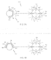
- FIG. 1 is a conceptual layout diagram of an exemplary remotely operated vehicle (ROV) control system in accordance with the subject matter described herein;
- ROV remotely operated vehicle
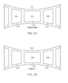
- FIG. 2A is a conceptual layout diagram of a plurality of displays mounted in an exemplary headset, looking forward from the operator's perspective in the context of the ROV control system of FIG. 1 ;
- FIG. 2B is a conceptual layout diagram of a plurality of displays mounted in an exemplary headset, looking to the left from the operator's perspective in the context of the ROV control system of FIG. 1 ;
- FIG. 3 is a schematic block diagram illustrating various functional modules of a remote controlled surveillance system in accordance with the present disclosure.
- FIG. 4 is a flow chart diagram of a method of manipulating the field of view of a surveillance system in accordance with the present disclosure.
- an embodiment of a system or a component may employ various integrated circuit components, e.g., memory elements, digital signal processing elements, logic elements, look-up tables, or the like, which may carry out a variety of functions under the control of one or more microprocessors or other control devices.
- integrated circuit components e.g., memory elements, digital signal processing elements, logic elements, look-up tables, or the like, which may carry out a variety of functions under the control of one or more microprocessors or other control devices.
- DSP digital signal processor
- ASIC application specific integrated circuit
- FPGA field programmable gate array
- a general-purpose processor may be a microprocessor, but in the alternative, the processor may be any conventional processor, controller, microcontroller, or state machine.
- a processor may also be implemented as a combination of computing devices, e.g., a combination of a DSP and a microprocessor, a plurality of microprocessors, one or more microprocessors in conjunction with a DSP core, or any other such configuration.
- the word "exemplary” is used exclusively herein to mean “serving as an example, instance, or illustration.” Any embodiment described herein as "exemplary” is not necessarily to be construed as preferred or advantageous over other embodiments.
- a software module may reside in RAM memory, flash memory, ROM memory, EPROM memory, EEPROM memory, registers, hard disk, a removable disk, a CD-ROM, or any other form of storage medium known in the art.
- An exemplary storage medium is coupled to the processor such the processor can read information from, and write information to, the storage medium.
- the storage medium may be integral to the processor.
- the processor and the storage medium may reside in an ASIC.
- the ASIC may reside in a user terminal.
- the processor and the storage medium may reside as discrete components in a user terminal
- a system 100 for dynamically reproducing a remote audiovisual environment includes a remotely operated vehicle (ROV) 102 and a headset 104 physically displaced from the ROV.
- ROV 102 is shown oriented in the forward direction (indicated by the arrow 112).
- a first camera 106 has an associated field of view 124 in the forward direction.
- a second camera 108 has a field of view 126 which is oriented to the left with respect to the forward direction (arrow 112).
- a third camera 110 has a field of view 128 oriented to the right with respect to arrow 112.
- first camera 106 is mounted to the front of ROV 102
- second camera 108 is mounted to a first side of ROV 102
- third camera 110 is mounted to the opposite side of ROV 102.
- Respective first and second microphones 130 and 132 are mounted on opposing sides of ROV 102.
- Each microphone has a "field of regard", or a zone within which acoustic information is captured.
- the precise geometry of the field of regard will be determined by the orientation and hardware configuration of the microphone assemblies.
- each microphone has an associated field of regard which is in part determined by the location of the microphone on ROV 102. It will be appreciated that any number and configuration of cameras, microphones, and other sensors may be employed for gathering data from the local environment surrounding ROV 102.
- Headset 104 may be in the form of a helmet, visor, earmuffs, a halo brace, or any other configuration which presents one or more visual and audio displays to the operator, and which facilitates tracking of operator movement such as, for example, movement of the operator's head, eyes, limbs, hands, foot, fingers, neck, or any other body part or physiological or sensory parameter (including but not limited to voice, respiration, and the like).
- one or more tracking modules 117 for example, an accelerometer, may be incorporated into or otherwise associated with headset 104.
- headset 104 includes a visor module 116 and a template assembly 115 for removably securing visor module 116 to the operator's head.
- Headset 104 further includes a first speaker 118 proximate the operator's left ear, and a second speaker 120 proximate the operator's right ear.
- speakers 118, 120 may comprise a single source acoustic driver (magnet), or a speaker assembly such as, for example, a dynamic virtual auditory display (DVAD) device.
- magnet single source acoustic driver
- DVAD dynamic virtual auditory display
- FIG. 1 illustrates a first orientation 121 of an operator facing in a forward direction (along arrow 112), and a second orientation 122 in which the operator has turned his head to the left with respect to arrow 112.
- FIG. 2A represents the operator's view of the inside of visor module 116 when the operator is facing forward (orientation 121 in FIG. 1 ).
- FIG 2B represents the operator's view when the operator turns his head to the left as shown by arrow 114 (orientation 122 in FIG. 1 ).
- the hardware associated with headset 104 does not move relative the operator's head.
- the video image presented to the operator does change as a function of head motion; that is, a different camera field of view or a combination or composite (e.g., stitching) of different fields of view is presented to the operator as a dynamic function of the output of tracker module 117.
- visor module 116 includes a primary internal display 124 located in the center (e.g., between and in front of the operator's eyes), one or more first peripheral displays 126 disposed to the left of primary display 124, and one or more second peripheral displays 128 located to the right of primary display 124.
- headset 104 When headset 104 is in a first position, for example, orientation 121, the operator's forward looking vector is generally parallel to the forward looking vector associated with ROV 102, i.e., along arrow 112.
- field of view 124 associated with camera 106 is presented to the operator on primary display 124.
- field of view 126 (camera 108) is presented on first peripheral display 126, and field of view 128 (corresponding to camera 110) is presented on second peripheral display 128.
- an acoustic signal from microphone 130 is presented to speaker 118, and an acoustic signal from microphone 132 is presented to speaker 120.
- Tracking module 117 detects this movement (change in head position) and, in response, the system manipulates the video image(s) presented to the operator.
- FIG. 2B illustrates the operator's view associated with orientation 122.
- field of view 126 (camera 108) is presented on primary display 204
- field of view 124 (camera 106) is presented on peripheral display 208.
- any number and configuration of cameras, microphones, displays and other sensors may be employed to reproduce or simulate a virtual presence, allowing the operator to effectively experience the local environment of ROV 102 remotely from headset 104.
- FIG. 3 is a block diagram of a remotely controlled surveillance system 300 including a surveillance platform 302 and a remote control system 304.
- Platform 302 includes an ROV 306 having respective cameras 316, 318, 320, and 322, as well as respective microphones 322, 324, and 326 mounted to the platform.
- Platform 302 further includes a data processing module 308, a multiplexor module 310, a demultiplexor module 314, and a data link 312.
- the various cameras, microphones, and/or other sensors (not shown) associated with ROV 306 are configured to feed raw sensory data (e.g., video and audio signals) to processor module 308.
- Processor module 308 process the raw data. Processing may include selecting which sensor data to process, stabilization (e.g., image stabilization), image stitching, data compression, image and/or audio enhancement, and filtering.
- the processed data is then applied to multiplexor module 310, and a multiplexed signal 311 is applied to data link 312.
- the multiplexed data may then be transmitted to remote control system 304, either wirelessly or via a hardware tether (not shown).
- remote control system 304 includes a data link 350, a demultiplexor module 352, a data processing module 354, a multiplexor module 376, a headset 356, and first and second auxiliary display units 364 and 370.
- Data link 350 and data link 312 cooperate to form a bidirectional data link for sending and receiving data back and forth between surveillance platform 302 and control system 304.
- the data received by data link 350 is applied to demultiplexor module 352.
- the resulting demultiplexed signals are applied to data processor module 354 and converted into individual data streams (e.g., audio and video signals).
- the individual data streams are selectively applied to various operator viewing and playback devices, discussed below.
- headset 356 includes a left speaker 358, a right speaker 360, a visor module 361 including one or more video displays (not shown), and a tracking module 362, also referred to as a field of view (FOV) controller.
- First auxiliary display 364 includes a speaker 366 and a FOV controller 368; auxiliary display 370 includes a speaker 372 and an FOV controller 374.
- tracking module 362 and FOV controllers 368 and 374 all operate independently. That is, they can each select a desired orientation or viewing perspective from ROV 302. Specifically, respective control signals from tracking module 362, FOV 368, and FOV 374 are applied to multiplexor module 376. The resulting multiplexed signal 378 is applied to data link 350 and transmitted to data link 312. The corresponding control signal 315 is demultiplexed by demultiplexor module 314, and the demultiplexed signals are applied to processing module 308. Based on these control signals, module 308 selects the appropriate data streams (in particular, camera fields of view) to be transmitted back the requesting FOV controller.
- data streams in particular, camera fields of view
- the method includes detecting (task 402) the motion and/or position of the tracking module, i.e., detecting whether the headset is in a forward orientation, a leftward orientation, or a rightward orientation.
- the method further includes presenting (task 404) the forward field of view on the forward display, the left field of view on the left display, and the right field of view on the right display when said headset is in the forward orientation, and presenting (task 406) the left field of view on the forward display and the forward field of view on the right display when the headset is in the leftward orientation.
- the method further involves presenting (task 408) the right field of view on the forward display and the forward field of view on the left display when the headset is in the rightward orientation.
Landscapes
- Engineering & Computer Science (AREA)
- Multimedia (AREA)
- Signal Processing (AREA)
- Radar, Positioning & Navigation (AREA)
- Remote Sensing (AREA)
- Aviation & Aerospace Engineering (AREA)
- Physics & Mathematics (AREA)
- General Physics & Mathematics (AREA)
- Automation & Control Theory (AREA)
- Selective Calling Equipment (AREA)
- Studio Devices (AREA)
- Testing Or Calibration Of Command Recording Devices (AREA)
Applications Claiming Priority (1)
| Application Number | Priority Date | Filing Date | Title |
|---|---|---|---|
| US13/406,212 US20130222590A1 (en) | 2012-02-27 | 2012-02-27 | Methods and apparatus for dynamically simulating a remote audiovisual environment |
Publications (2)
| Publication Number | Publication Date |
|---|---|
| EP2631728A2 true EP2631728A2 (fr) | 2013-08-28 |
| EP2631728A3 EP2631728A3 (fr) | 2017-04-05 |
Family
ID=47900525
Family Applications (1)
| Application Number | Title | Priority Date | Filing Date |
|---|---|---|---|
| EP13155696.1A Withdrawn EP2631728A3 (fr) | 2012-02-27 | 2013-02-18 | Procédés et appareil de simulation dynamique d'un environnement audiovisuel à distance |
Country Status (2)
| Country | Link |
|---|---|
| US (1) | US20130222590A1 (fr) |
| EP (1) | EP2631728A3 (fr) |
Cited By (2)
| Publication number | Priority date | Publication date | Assignee | Title |
|---|---|---|---|---|
| EP3216004A4 (fr) * | 2014-11-07 | 2018-06-27 | Bae Systems Hägglunds Aktiebolag | Système de connaissance de la situation et procédé de connaissance de la situation dans un véhicule de combat |
| EP3547663A1 (fr) * | 2018-03-27 | 2019-10-02 | Honeywell International Inc. | Système de vision panoramique avec atténuation de parallaxe |
Families Citing this family (9)
| Publication number | Priority date | Publication date | Assignee | Title |
|---|---|---|---|---|
| US20140327733A1 (en) | 2012-03-20 | 2014-11-06 | David Wagreich | Image monitoring and display from unmanned vehicle |
| US9350954B2 (en) * | 2012-03-20 | 2016-05-24 | Crane-Cohasset Holdings, Llc | Image monitoring and display from unmanned vehicle |
| US10063782B2 (en) * | 2013-06-18 | 2018-08-28 | Motorola Solutions, Inc. | Method and apparatus for displaying an image from a camera |
| GB2525170A (en) * | 2014-04-07 | 2015-10-21 | Nokia Technologies Oy | Stereo viewing |
| EP3328731B1 (fr) * | 2015-07-28 | 2020-05-06 | Margolin, Joshua | Procédé de commande de vol d'un uav à plusieurs rotors |
| DE102015118540B4 (de) * | 2015-10-29 | 2021-12-02 | Geomar Helmholtz-Zentrum Für Ozeanforschung Kiel - Stiftung Des Öffentlichen Rechts | Tauchroboter-Bild-/Videodatenvisualisierungssystem |
| US10339352B2 (en) | 2016-06-03 | 2019-07-02 | Hand Held Products, Inc. | Wearable metrological apparatus |
| US11622100B2 (en) * | 2021-02-17 | 2023-04-04 | flexxCOACH VR | 360-degree virtual-reality system for dynamic events |
| EP4163765A1 (fr) * | 2021-10-07 | 2023-04-12 | Koninklijke Philips N.V. | Procédé et appareil pour déclencher une action |
Family Cites Families (8)
| Publication number | Priority date | Publication date | Assignee | Title |
|---|---|---|---|---|
| US6925357B2 (en) * | 2002-07-25 | 2005-08-02 | Intouch Health, Inc. | Medical tele-robotic system |
| JP2006503375A (ja) * | 2002-10-18 | 2006-01-26 | サーノフ・コーポレーション | 複数のカメラを用いたパノラマ映像化を可能とする方法およびシステム |
| US7495638B2 (en) * | 2003-05-13 | 2009-02-24 | Research Triangle Institute | Visual display with increased field of view |
| WO2007045016A1 (fr) * | 2005-10-20 | 2007-04-26 | Personal Audio Pty Ltd | Simulation audio spatiale |
| US9270976B2 (en) * | 2005-11-02 | 2016-02-23 | Exelis Inc. | Multi-user stereoscopic 3-D panoramic vision system and method |
| IL189251A0 (en) * | 2008-02-05 | 2008-11-03 | Ehud Gal | A manned mobile platforms interactive virtual window vision system |
| US8170241B2 (en) * | 2008-04-17 | 2012-05-01 | Intouch Technologies, Inc. | Mobile tele-presence system with a microphone system |
| US20110291918A1 (en) * | 2010-06-01 | 2011-12-01 | Raytheon Company | Enhancing Vision Using An Array Of Sensor Modules |
-
2012
- 2012-02-27 US US13/406,212 patent/US20130222590A1/en not_active Abandoned
-
2013
- 2013-02-18 EP EP13155696.1A patent/EP2631728A3/fr not_active Withdrawn
Non-Patent Citations (1)
| Title |
|---|
| None |
Cited By (3)
| Publication number | Priority date | Publication date | Assignee | Title |
|---|---|---|---|---|
| EP3216004A4 (fr) * | 2014-11-07 | 2018-06-27 | Bae Systems Hägglunds Aktiebolag | Système de connaissance de la situation et procédé de connaissance de la situation dans un véhicule de combat |
| EP3547663A1 (fr) * | 2018-03-27 | 2019-10-02 | Honeywell International Inc. | Système de vision panoramique avec atténuation de parallaxe |
| US10582181B2 (en) | 2018-03-27 | 2020-03-03 | Honeywell International Inc. | Panoramic vision system with parallax mitigation |
Also Published As
| Publication number | Publication date |
|---|---|
| US20130222590A1 (en) | 2013-08-29 |
| EP2631728A3 (fr) | 2017-04-05 |
Similar Documents
| Publication | Publication Date | Title |
|---|---|---|
| EP2631728A2 (fr) | Procédés et appareil de simulation dynamique d'un environnement audiovisuel à distance | |
| JP7470164B2 (ja) | 双方向性拡張または仮想現実装置 | |
| US20230388467A1 (en) | Immersive display and method of operating immersive display for real-world object alert | |
| EP3029552B1 (fr) | Système de réalité virtuelle et procédé de commande de modes de fonctionnement d'un tel système | |
| EP3177010B1 (fr) | Dispositif de traitement d'informations, procédé de traitement d'informations et système d'affichage d'images | |
| CN105700676A (zh) | 可佩戴眼镜及其控制方法、以及车辆控制系统 | |
| US20130250078A1 (en) | Visual aid | |
| CN112154047A (zh) | 远程操作系统、信息处理方法以及程序 | |
| JP6822410B2 (ja) | 情報処理システム及び情報処理方法 | |
| US20160286115A1 (en) | Front field of view camera for mobile device | |
| EP3495942B1 (fr) | Visiocasque et son procédé de commande | |
| JP2023531849A (ja) | オーディオ認識を行う拡張現実デバイスおよびその制御方法 | |
| US20190121515A1 (en) | Information processing device and information processing method | |
| US20170337736A1 (en) | Threat warning system adapted to a virtual reality display system and method thereof | |
| JP6540572B2 (ja) | 表示装置および表示制御方法 | |
| CN115185080A (zh) | 一种车用可穿戴ar抬头显示系统 | |
| CN117121474A (zh) | 影像显示系统、观测装置、信息处理方法及程序 | |
| JP7065353B2 (ja) | ヘッドマウントディスプレイ及びその制御方法 | |
| US20150174501A1 (en) | Personal camera for a remote vehicle | |
| KR101655826B1 (ko) | 웨어러블 글래스, 그 제어 방법 및 차량 제어 시스템 | |
| KR100748162B1 (ko) | 헬멧을 이용한 실시간 영상 디스플레이 장치 및 그를이용한 무인항공기의 카메라 조절 장치 | |
| WO2016173599A1 (fr) | Système d'images d'objets | |
| TR2022008128T2 (tr) | Görme engelli̇ler i̇çi̇n i̇şi̇tsel artirilmiş gerçekli̇k özelli̇kli̇ bi̇r navi̇gasyon yardim si̇stemi̇ | |
| IT201900013200A1 (it) | Sistema di interazione multimediale, particolarmente per applicazioni turistiche e ludiche | |
| JP2000275058A (ja) | 管制々御システム |
Legal Events
| Date | Code | Title | Description |
|---|---|---|---|
| PUAI | Public reference made under article 153(3) epc to a published international application that has entered the european phase |
Free format text: ORIGINAL CODE: 0009012 |
|
| 17P | Request for examination filed |
Effective date: 20130218 |
|
| AK | Designated contracting states |
Kind code of ref document: A2 Designated state(s): AL AT BE BG CH CY CZ DE DK EE ES FI FR GB GR HR HU IE IS IT LI LT LU LV MC MK MT NL NO PL PT RO RS SE SI SK SM TR |
|
| AX | Request for extension of the european patent |
Extension state: BA ME |
|
| RAP1 | Party data changed (applicant data changed or rights of an application transferred) |
Owner name: HONEYWELL INTERNATIONAL INC. |
|
| PUAL | Search report despatched |
Free format text: ORIGINAL CODE: 0009013 |
|
| AK | Designated contracting states |
Kind code of ref document: A3 Designated state(s): AL AT BE BG CH CY CZ DE DK EE ES FI FR GB GR HR HU IE IS IT LI LT LU LV MC MK MT NL NO PL PT RO RS SE SI SK SM TR |
|
| AX | Request for extension of the european patent |
Extension state: BA ME |
|
| RIC1 | Information provided on ipc code assigned before grant |
Ipc: H04N 7/18 20060101ALI20170302BHEP Ipc: H04N 5/232 20060101ALI20170302BHEP Ipc: G05D 1/00 20060101AFI20170302BHEP |
|
| 17Q | First examination report despatched |
Effective date: 20170324 |
|
| STAA | Information on the status of an ep patent application or granted ep patent |
Free format text: STATUS: THE APPLICATION IS DEEMED TO BE WITHDRAWN |
|
| 18D | Application deemed to be withdrawn |
Effective date: 20180706 |