EP2631996B1 - Dispositif d'alimentation en énergie pour une borne de connexion de lampes et lampe - Google Patents
Dispositif d'alimentation en énergie pour une borne de connexion de lampes et lampe Download PDFInfo
- Publication number
- EP2631996B1 EP2631996B1 EP13000894.9A EP13000894A EP2631996B1 EP 2631996 B1 EP2631996 B1 EP 2631996B1 EP 13000894 A EP13000894 A EP 13000894A EP 2631996 B1 EP2631996 B1 EP 2631996B1
- Authority
- EP
- European Patent Office
- Prior art keywords
- lamp
- housing
- connecting terminal
- connection terminal
- terminal
- Prior art date
- Legal status (The legal status is an assumption and is not a legal conclusion. Google has not performed a legal analysis and makes no representation as to the accuracy of the status listed.)
- Active
Links
Images



Classifications
-
- H—ELECTRICITY
- H01—ELECTRIC ELEMENTS
- H01R—ELECTRICALLY-CONDUCTIVE CONNECTIONS; STRUCTURAL ASSOCIATIONS OF A PLURALITY OF MUTUALLY-INSULATED ELECTRICAL CONNECTING ELEMENTS; COUPLING DEVICES; CURRENT COLLECTORS
- H01R13/00—Details of coupling devices of the kinds covered by groups H01R12/70 or H01R24/00 - H01R33/00
- H01R13/73—Means for mounting coupling parts to apparatus or structures, e.g. to a wall
- H01R13/74—Means for mounting coupling parts in openings of a panel
- H01R13/741—Means for mounting coupling parts in openings of a panel using snap fastening means
- H01R13/743—Means for mounting coupling parts in openings of a panel using snap fastening means integral with the housing
-
- H—ELECTRICITY
- H01—ELECTRIC ELEMENTS
- H01R—ELECTRICALLY-CONDUCTIVE CONNECTIONS; STRUCTURAL ASSOCIATIONS OF A PLURALITY OF MUTUALLY-INSULATED ELECTRICAL CONNECTING ELEMENTS; COUPLING DEVICES; CURRENT COLLECTORS
- H01R13/00—Details of coupling devices of the kinds covered by groups H01R12/70 or H01R24/00 - H01R33/00
- H01R13/46—Bases; Cases
- H01R13/50—Bases; Cases formed as an integral body
- H01R13/501—Bases; Cases formed as an integral body comprising an integral hinge or a frangible part
-
- H—ELECTRICITY
- H01—ELECTRIC ELEMENTS
- H01R—ELECTRICALLY-CONDUCTIVE CONNECTIONS; STRUCTURAL ASSOCIATIONS OF A PLURALITY OF MUTUALLY-INSULATED ELECTRICAL CONNECTING ELEMENTS; COUPLING DEVICES; CURRENT COLLECTORS
- H01R4/00—Electrically-conductive connections between two or more conductive members in direct contact, i.e. touching one another; Means for effecting or maintaining such contact; Electrically-conductive connections having two or more spaced connecting locations for conductors and using contact members penetrating insulation
- H01R4/28—Clamped connections, spring connections
- H01R4/48—Clamped connections, spring connections utilising a spring, clip, or other resilient member
- H01R4/4809—Clamped connections, spring connections utilising a spring, clip, or other resilient member using a leaf spring to bias the conductor toward the busbar
- H01R4/48185—Clamped connections, spring connections utilising a spring, clip, or other resilient member using a leaf spring to bias the conductor toward the busbar adapted for axial insertion of a wire end
- H01R4/4819—Clamped connections, spring connections utilising a spring, clip, or other resilient member using a leaf spring to bias the conductor toward the busbar adapted for axial insertion of a wire end the spring shape allowing insertion of the conductor end when the spring is unbiased
- H01R4/4821—Single-blade spring
-
- H—ELECTRICITY
- H01—ELECTRIC ELEMENTS
- H01R—ELECTRICALLY-CONDUCTIVE CONNECTIONS; STRUCTURAL ASSOCIATIONS OF A PLURALITY OF MUTUALLY-INSULATED ELECTRICAL CONNECTING ELEMENTS; COUPLING DEVICES; CURRENT COLLECTORS
- H01R4/00—Electrically-conductive connections between two or more conductive members in direct contact, i.e. touching one another; Means for effecting or maintaining such contact; Electrically-conductive connections having two or more spaced connecting locations for conductors and using contact members penetrating insulation
- H01R4/28—Clamped connections, spring connections
- H01R4/48—Clamped connections, spring connections utilising a spring, clip, or other resilient member
- H01R4/4809—Clamped connections, spring connections utilising a spring, clip, or other resilient member using a leaf spring to bias the conductor toward the busbar
- H01R4/4828—Spring-activating arrangements mounted on or integrally formed with the spring housing
- H01R4/483—Pivoting arrangements, e.g. lever pushing on the spring
-
- H—ELECTRICITY
- H01—ELECTRIC ELEMENTS
- H01R—ELECTRICALLY-CONDUCTIVE CONNECTIONS; STRUCTURAL ASSOCIATIONS OF A PLURALITY OF MUTUALLY-INSULATED ELECTRICAL CONNECTING ELEMENTS; COUPLING DEVICES; CURRENT COLLECTORS
- H01R4/00—Electrically-conductive connections between two or more conductive members in direct contact, i.e. touching one another; Means for effecting or maintaining such contact; Electrically-conductive connections having two or more spaced connecting locations for conductors and using contact members penetrating insulation
- H01R4/28—Clamped connections, spring connections
- H01R4/48—Clamped connections, spring connections utilising a spring, clip, or other resilient member
- H01R4/4809—Clamped connections, spring connections utilising a spring, clip, or other resilient member using a leaf spring to bias the conductor toward the busbar
- H01R4/4846—Busbar details
- H01R4/485—Single busbar common to multiple springs
-
- H—ELECTRICITY
- H01—ELECTRIC ELEMENTS
- H01R—ELECTRICALLY-CONDUCTIVE CONNECTIONS; STRUCTURAL ASSOCIATIONS OF A PLURALITY OF MUTUALLY-INSULATED ELECTRICAL CONNECTING ELEMENTS; COUPLING DEVICES; CURRENT COLLECTORS
- H01R9/00—Structural associations of a plurality of mutually-insulated electrical connecting elements, e.g. terminal strips or terminal blocks; Terminals or binding posts mounted upon a base or in a case; Bases therefor
- H01R9/22—Bases, e.g. strip, block, panel
- H01R9/24—Terminal blocks
- H01R9/2491—Terminal blocks structurally associated with plugs or sockets
Definitions
- the invention relates to a device for energy supply for a lamp connection terminal according to the preamble of claim 1, and a lamp.
- Luminaire connection terminals are generally known and are usually arranged on the inside of the luminaire.
- the power cable is fed from the outside of the lamp through an opening in the lamp housing into the inside of the lamp and connected to the lamp connection terminal.
- the assembly is complex because the luminaire is to be opened so that the electrical conductors can be plugged in or out of the luminaire connection terminal. For this purpose, if the electrical line is to be passed on to a further luminaire, it should in turn first be fed out of the luminaire.
- a lamp connection terminal is arranged entirely within a lamp housing.
- Individual clamping elements are present in the device, it being possible for conductors of an electrical line to be connected in the individual clamping elements.
- Plug pins enable electrical contacting between the individual clamping elements and the lamp connection terminal, the electrical contacting being automatically provided when the device is mechanically fixed on the lamp housing. This can be disadvantageous for security reasons.
- the invention has for its object to provide a device for power supply for a lamp connector of the types mentioned in such a way that the assembly or disassembly of the device and the connection of the electrical line with the lamp connector in the lamp is improved and simplified, taking the necessary safety precautions should remain guaranteed. Furthermore, the manufacture of the device is to be simplified.
- the device according to the invention for energy supply for a lamp connection terminal has at least one connection adapter and a connection terminal, the connection adapter and the connection terminal being able to be arranged essentially outside a lamp housing of a lamp, the lamp connection terminal being able to be arranged essentially inside the lamp housing of the lamp, the device is electrically contactable with the lamp connection terminal, at least one electrical conductor of an electrical line, preferably a mains line, being used the device is directly or indirectly electrically contacted with the lamp connection terminal.
- connection terminal of the device essentially corresponds to the type of terminal of the luminaire connecting terminal.
- connection terminal of the device it is essential for the device that at least the electrical connections or the electrical contact parts of the connection terminal of the device are essentially identical to the electrical connections or electrical contact parts of the lamp connection terminal.
- the electrical connections are also called connection poles here.
- the electrical contact parts are also called stamped parts.
- the electrical conductors of the electrical line can be connected outside the lamp.
- the mains cable can then be fed in outside the luminaire.
- the assembly and disassembly is simplified and less complex because the lamp does not have to be opened.
- the forwarding of the electrical line to another lamp is also simplified.
- the electrical line with at least one electrical conductor can be led directly from the connection adapter outside the lamp to the next lamp, preferably to a further connection adapter of another device.
- the connection adapter is used for the power supply and can also be used for looping through for another luminaire.
- connection terminals are essentially identical, the production of such a terminal can be optimized, can be produced in larger quantities and the automation for the production can also be increased.
- the assembly of both connection terminals can also be automated and can advantageously be carried out on the same assembly system.
- connection adapter has a connection adapter fixed part and a connection adapter sliding part, the design being such that the connection adapter sliding part can be displaced relative to the connection adapter fixed part.
- Luminaire connection terminal for the luminaire can also be provided in the device.
- connection terminal of the device it is not necessary for the invention that the mechanical fastening elements of the connection terminal of the device have to be provided identically to the mechanical fastening elements of the lamp connection terminal, since the connection terminal in the connection adapter can be attached differently than the fastening of the lamp connection terminal on the lamp housing, especially for reasons of space.
- connection terminals in the device and in the luminaire, can preferably be conventional or standard mains connection terminals.
- connection terminal designed as a lamp connection terminal is arranged in the connection adapter of the device, for example in a receptacle of the connection adapter.
- connection terminal can have at least one housing with an upper and a lower region.
- the lamp connection terminal can also have at least one housing with an upper and a lower area.
- the upper area of the housing of the connection terminal can be configured essentially identically to an upper area of the housing of the provided light connection terminal.
- the terminal structure within the upper area of the housing of the connection terminal can be configured essentially identically to the terminal structure within the upper area of the housing of the provided light connection terminal.
- the electrical conductors of the electrical line can be inserted and / or removed from the connection poles of the connection terminal of the device without tools.
- the electrical conductors of the electrical line can be connected by a specialist in connection poles of the connection terminal of the device.
- connection adapter with the connection terminal in the connection adapter significantly simplifies the handling, assembly and disassembly of the electrical line for a lamp, since the lamp is no longer to be opened.
- the electrical conductors of the power line can be connected as before. This can be done by a specialist, preferably an electrician.
- the electrical power line is provided with a plug and that the connection terminal of the device is accordingly equipped with the counterpart of the plug in order in turn to enable the electrical power line to be connected to the device.
- an interface preferably known per se, can be present on the luminaire housing, it being possible for the device and the luminaire connection terminal to be contacted via the interface.
- the interface can also be used to fasten the device and / or the lamp connection terminal.
- a universal die cut pattern can be provided in the luminaire housing.
- the device and the lamp connection terminal can be provided with a corresponding or matching interface and / or coding.
- various devices and luminaire connection terminals may be necessary; the coding can prevent incorrect installation.
- the light connection terminal can have a lower area on the housing, which is designed with its fastening elements to match the interface on the light housing, the fastening elements additionally having a defined coding.
- the lower area of the housing of the connection terminal can, for example, be designed to be flatter or to match the receptacle in the connection adapter, the lower area of the housing having fastening elements that have a smaller design than the fastening elements of the lamp connection terminal.
- fastening elements for the connection terminal are present on the connection adapter, and in this case only holding or guiding elements are provided on the connection terminal, the design of the lower region of the housing of the connection terminal also being smaller than the design of the lower area of the housing of the lamp connection terminal.
- a coding can be provided in the connection adapter, which should be compatible with the coding of the lower area of the housing of the lamp connection terminal.
- the coding in the connection adapter can be present, for example, on the connection adapter fixed part and / or in an additional interface, which can preferably have at least one slider and a holding cover.
- At least one contact element can be provided between the connection terminal of the device and the light connection terminal within the light for electrical contacting of the device with the light connection terminal.
- the contact element (s) can be designed as a fork contact.
- the contact element can be designed as a fork contact on both sides.
- the fork legs of the fork contacts can be designed to be resilient so that lateral contacting can occur.
- the contact element can also have a fork contact on one side and a resilient tab on the other side.
- One contact element per connection pole can preferably be provided.
- the contact element can, for example, be arranged on one side in the connection terminal of the device, preferably inserted.
- the other side of the contact element can penetrate through a recess in the connection adapter in the assembled state.
- the contact element When assembled and contacted, the contact element can penetrate the lower area of the housing of the lamp connection terminal and create the electrical contact within the lamp connection terminal.
- connection adapter is designed in two parts, with a connection adapter fixed part and a connection adapter sliding part.
- the advantage is that the electrical contact between the connection terminal of the device and the lamp connection terminal can be interrupted, even if the electrical conductors of the electrical line are connected in the connection terminal of the device. If the connection adapter is decoupled or if the connection adapter sliding part is not snapped into the connection adapter fixed part, but is still present on the luminaire housing, the contact elements are no longer contacted with the luminaire connection terminal, resulting in protection against accidental contact.
- the principle can be known per se.
- non-electrical contact elements for contacting the device with the lamp connection terminal are present within the lamp.
- These contact elements can serve, for example, as positioning or guidance between the two parts. They can be designed as separate parts or as part of the connection adapter and / or the lamp connection terminal within the lamp.
- the device or the connection adapter can preferably also be mechanically attached to the lamp housing.
- the connection adapter can be mounted on the luminaire housing without making electrical contact between the connection terminal of the device and the luminaire connection terminal within the luminaire housing.
- connection adapter can have, for example, holding elements and the light housing can have fastening holes, the holding elements of the connection adapter being held in the fastening holes of the light housing. Mechanical fixation and stabilization of the device on the lamp housing can thus be provided.
- connection point of the power line in the device should not be open in the operating state. This can preferably be achieved by providing the device with a cover. When installed, this cover lies over the connection terminal of the connection adapter and can also cover the electrical conductors of the mains cable.
- the cover can, for example, be pivotally attached to the connection adapter, preferably to the connection adapter sliding part of the connection adapter. It is also conceivable that this protective cover can be displaceable or even completely extendable.
- the type of attachment of the lid to the device can be done in a manner known per se, e.g. with holding elements.
- a strain relief device can be provided for the electrical line. It can be arranged in the device or on the lamp housing. Alternatively, at least a part of the strain relief device can be formed in one piece with the connection adapter of the device. Another part of the strain relief device can either be designed as a swivel arm and on an axis of rotation of the Connection adapter can be arranged or the further part of the strain relief device can be designed as a sliding part and screwed to the first part. It can also be a known strain relief device.
- the invention relates to a lamp with the device according to the invention for supplying energy for a lamp connection terminal.
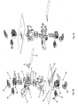
- FIG. 1a and Fig. 1b are perspective views of a device 1 according to the invention, which can be mounted on a schematically illustrated lamp housing 16.
- the device 1 is mounted outside the lamp.
- a lamp connection terminal 20 is fastened within the lamp or the lamp housing 16.
- FIG. 2a and Fig. 2b are perspective views of the device 1 shown, in contrast to Fig. 1a and 2 B the lid 12 of the device 1 is open.
- the device 1 has a connection adapter 2, the connection adapter 2 consisting at least of a connection adapter fixed part 3 and a connection adapter sliding part 4.
- a receptacle 5 is provided in the connecting adapter sliding part 4, which can be used for the arrangement of a connecting terminal 8.
- connection terminal 8 can be a connection terminal known per se.
- Connection poles 11 are provided in the connection terminal 8 for the connection of electrical conductors 15 of an electrical line 14.
- the device 1 has a cover 12, which is pivotally arranged here on the connection adapter 2. In the closed state, this cover 12 serves as protection against contact.
- One or more holding elements 25 on the cover 12 enable the cover 12 to be fastened in or in the receptacles 26 on the connection adapter 2 so that the cover can be kept closed.
- a strain relief device 13 for the electrical line 14 is also provided here in this exemplary embodiment of the device 1. It is arranged on the connecting adapter sliding part 4.
- the device 1 can be mechanically attached to the lamp housing 16 via its holding elements 7.
- the holding elements 7 of the device 1 can be mounted in recesses 18 of the lamp housing 16. Holding hooks can be provided here, but also other holding means known per se.
- a lamp connector 20 is attached on the other side of the lamp housing 16, ie inside the lamp.
- 20 recesses are provided for fastening the luminaire connection terminal, which serve as interface 17 here.
- the lower region 22 of the housing 39 of the lamp connection terminal 20 has fastening elements 32 which can be fastened in the interface 17.
- Recesses 6 are provided below the device 1, on the connection adapter fixed part 3, which are adapted at the interface 17. In this embodiment, the cutouts 6 also serve as coding for the interface 17.
- connection adapter fixed part 3 and the connection adapter sliding part 4 preferably has at least one slide control 24 and a holding cover 29.
- connection terminal 8 of the device 1 and the lamp connection terminal 20 can be made by means of the electrical contact elements 19.
- the contact elements 19 are designed on the one hand as a resilient tab and are inserted in the connection terminal 8 through the cutouts 34 of the connection terminal 8. They are then in electrical contact with the stamped parts 28 of the connecting terminal 8.
- the electrical contact elements 19 are designed as fork contacts.
- the fork contacts penetrate through the connecting adapter sliding part 4, as well as through the interface and the connecting adapter fixed part 3.
- the holding cover 29 of the interface serves as an additional guide for the contact elements 19.
- the holding cover 29 always remains in the same position in comparison to the connecting adapter sliding part 4.
- the slider 24 serves as additional protection against contact for the contact elements 19. If the device 1 is not fully contacted with the lamp connection terminal 20, the slider 24 also blocks the contact elements 19 or the connector 8 from possible electrical contact with the lamp connection terminal 20.
- the slide controller 24 can have cutouts which can only be penetrated by the contact elements 19 in the contacted state. Otherwise are for example, the contact elements 19 are not in alignment with the cutouts of the slider 24.
- the electrical contact elements 19 When the device 1 is electrically contacted with the lamp connection terminal 20, the electrical contact elements 19 still penetrate through the interface 17 of the lamp housing 16 and through the recesses 35 of the lamp connection terminal 20, and are in contact with the electrical stamped parts of the lamp connection terminal 20.
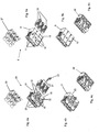
- connection terminal 20 4a, 4b and 4c
- connection terminal 8 of the device 1 5a, 5b, 5c
- the pushers 27 and 30 of both terminals 8 and 20 are identical.
- the stamped parts 28 and 31 of both terminals 8 and 20 are also identical.
- the upper regions 9 and 21 of both housings 38 and 39 of the terminals 8 and 20 are identical, so that the connection poles 11 and 23 of both terminals 8 and 20 are also identical.
- the light connection terminal 20 additionally has a grounding element 33.
- FIGS 6 to 9 The assembly of the device 1 on the luminaire housing 16 and its contacting with the luminaire connection terminal 20 is shown in FIGS 6 to 9 shown.
- the device 1 is first mechanically fastened in the sliding direction S1, here in the vertical direction, on the lamp housing 16, with its holding elements 7 being hooked into the fastening holes 18 in the lamp housing 16.
- the electrical contact elements 19 are located within the device 1 and do not come into contact with the electrical parts or the stamped parts 31 of the lamp connection terminal 20. Protection against accidental contact is available in this case.
- the slider 24 is still in a locked position for the contact elements 19.
- connection adapter fixed part 3 of the device 1 can be pushed in the sliding direction S2, here in the horizontal direction, so that the electrical contact elements 19 can be positioned in alignment with the recesses 35 of the lamp connection terminal 20.
- the slider 24 is thereby also released for the contact elements 19. At this assembly point, however, there is still no electrical contact between the connection terminal 8 of the device 1 and the lamp connection terminal 20.
- connection adapter sliding part 4 is shifted in the sliding direction S3, here in the vertical direction.
- the connecting terminal 8 and the electrical contact elements 19 are thus also displaced in the direction S3.
- the electrical contact elements 19 penetrate into the cutouts 35 in the lamp connection terminal 20 and enable electrical contact between the connection terminal 8 of the device 1 and the lamp connection terminal 20.
- the snap elements 36 of the connecting adapter sliding part 4 then snap onto retaining lugs 37 of the connecting adapter fixed part 3 in order to hold the connecting adapter sliding part 4 in position, as a security so that the electrical contacts cannot be unintentionally released by the contact elements 19.
Landscapes
- Arrangement Of Elements, Cooling, Sealing, Or The Like Of Lighting Devices (AREA)
- Fastening Of Light Sources Or Lamp Holders (AREA)
Claims (9)
- Arrangement comprenant une borne de raccordement de luminaire (20) et un dispositif (1) d'alimentation en énergie pour la borne de raccordement de luminaire (20), ce dispositif comprenant ce qui suit :- un adaptateur de raccordement (2),- une borne de raccordement (8),l'adaptateur de raccordement (2) et la borne de raccordement (8) pouvant être disposés globalement à l'extérieur d'un boîtier de luminaire (16) d'un luminaire,
la borne de raccordement de luminaire (20) pouvant être disposée globalement à l'intérieur du boîtier de luminaire (16) du luminaire,
le dispositif (1) pouvant être mis en contact électrique avec la borne de raccordement de luminaire (20),
au moins un conducteur électrique (15) d'une ligne électrique (14), de préférence une ligne de réseau, pouvant être mis en contact au moyen du dispositif (1) avec la borne de raccordement de luminaire (20),
la borne de raccordement (8) du dispositif (1) correspondant globalement au type de borne de la borne de raccordement de luminaire (20) et/ou au moins les raccordements électriques ou les pièces de contact électrique de la borne de raccordement (8) du dispositif (1) étant conçus de manière globalement identique aux raccordements électriques ou aux pièces de contact électrique de la borne de raccordement de luminaire (20),
caractérisée en ce que
l'adaptateur de raccordement (2) comprend une partie fixe d'adaptateur de raccordement (3) et une partie coulissante d'adaptateur de raccordement (4), la conception étant telle que la partie coulissante d'adaptateur de raccordement (4) peut être coulissée par rapport à la partie fixe d'adaptateur de raccordement (3). - Disposition selon la revendication 1,
caractérisée en ce que
la borne de raccordement (8) comprend au moins un boîtier (38) avec une partie supérieure (9) et une partie inférieure (10),
la partie supérieure (9) du boîtier (38) de la borne de raccordement (8) étant conçue de manière identique à une partie supérieure (21) du boîtier (39) de la borne de raccordement de luminaire (20). - Disposition selon la revendication 1 ou 2,
caractérisée en ce que
la structure de la borne à l'intérieur de la partie supérieure (9) du boîtier (38) de la borne de raccordement (8) est identique à la structure de la borne à l'intérieur de la partie supérieure (21) du boîtier (39) de la borne de raccordement de luminaire (20). - Disposition selon l'une des revendications précédentes,
caractérisée en ce que
au moins un élément de contact électrique (19) est prévu entre la borne de raccordement (8) du dispositif (1) et la borne de raccordement de luminaire (20) pour la mise en contact électrique du dispositif (1) avec la borne de raccordement de luminaire (20). - Disposition selon l'une des revendications précédentes,
caractérisée en ce que
le dispositif (1) est muni d'un couvercle (12) qui est disposé de préférence de manière pivotante sur l'adaptateur de raccordement (2). - Disposition selon l'une des revendications précédentes,
caractérisée en ce que
un dispositif de décharge de traction (13) est prévu sur le dispositif (1) pour la ligne électrique (14). - Luminaire comprenant- un boîtier de luminaire (16) et- une disposition selon l'une des revendications précédentes, la borne de raccordement de luminaire (20) étant disposée globalement à l'intérieur du boîtier de luminaire (16).
- Luminaire selon la revendication 7,
caractérisé en ce que
une interface (17) est prévue sur le boîtier de luminaire (16), la mise en contact entre le dispositif (1) et la borne de raccordement de luminaire (20) ayant lieu par l'intermédiaire de l'interface (17). - Luminaire selon la revendication 8,
caractérisé en ce que
la borne de raccordement de luminaire (20) comprend une partie inférieure (22) sur le boîtier (39), qui est réalisée de manière adaptée à l'interface (17) sur le boîtier de luminaire (16) et qui comprend en outre un codage et/ou en ce que, dans l'adaptateur de raccordement (2), un codage est prévu, qui est compatible avec le codage de la partie inférieure (22) du boîtier (39) de la borne de raccordement de luminaire (20).
Applications Claiming Priority (1)
| Application Number | Priority Date | Filing Date | Title |
|---|---|---|---|
| ATGM73/2012U AT13298U1 (de) | 2012-02-27 | 2012-02-27 | Vorrichtung zur Energieversorgung für eine Leuchtenanschlussklemme, sowie Leuchte |
Publications (3)
| Publication Number | Publication Date |
|---|---|
| EP2631996A2 EP2631996A2 (fr) | 2013-08-28 |
| EP2631996A3 EP2631996A3 (fr) | 2014-03-19 |
| EP2631996B1 true EP2631996B1 (fr) | 2019-12-25 |
Family
ID=48808122
Family Applications (1)
| Application Number | Title | Priority Date | Filing Date |
|---|---|---|---|
| EP13000894.9A Active EP2631996B1 (fr) | 2012-02-27 | 2013-02-22 | Dispositif d'alimentation en énergie pour une borne de connexion de lampes et lampe |
Country Status (2)
| Country | Link |
|---|---|
| EP (1) | EP2631996B1 (fr) |
| AT (1) | AT13298U1 (fr) |
Families Citing this family (2)
| Publication number | Priority date | Publication date | Assignee | Title |
|---|---|---|---|---|
| EP3522303B1 (fr) * | 2018-02-05 | 2022-09-07 | Schneider Electric Industries SAS | Bloc de raccordement |
| CN109888521A (zh) * | 2019-03-27 | 2019-06-14 | 余姚市信亿电子科技有限公司 | 接电结构及其壁灯 |
Family Cites Families (8)
| Publication number | Priority date | Publication date | Assignee | Title |
|---|---|---|---|---|
| DE29822575U1 (de) * | 1998-12-18 | 2000-04-20 | hülsta-werke Hüls GmbH & Co. KG, 48703 Stadtlohn | Vorrichtung zur Befestigung einer elektrischen Armatur an einem plattenförmigen Bauteil |
| DE10053302A1 (de) * | 2000-04-26 | 2001-10-31 | Wieland Electric Gmbh | Mehrpoliger elektrischer Anschlußverbinder |
| JP2003197312A (ja) * | 2001-12-27 | 2003-07-11 | Jst Mfg Co Ltd | ロック付き電気コネクタ |
| DE10236398B3 (de) | 2002-08-08 | 2004-04-29 | Wieland Electric Gmbh | Anschlusssystem |
| DE102005001821A1 (de) * | 2005-01-13 | 2006-07-27 | Wieland Electric Gmbh | Elektrischer Geräteanschluss |
| DE102008017915B4 (de) | 2008-04-08 | 2010-03-04 | Wago Verwaltungsgesellschaft Mbh | Set aus Anschlussadapter und Anschlussklemme sowie Anschlussadapter und Anschlusselement hierzu |
| FI122430B (fi) | 2010-02-12 | 2012-01-31 | Ensto Electric Oy | Liitin sähköjohtimien kytkemiseksi |
| DE202010006540U1 (de) * | 2010-05-07 | 2010-08-05 | Belux Ip Ag | Adapteranordnung zum Betrieb einer elektrischen Leuchte an einem Tisch |
-
2012
- 2012-02-27 AT ATGM73/2012U patent/AT13298U1/de not_active IP Right Cessation
-
2013
- 2013-02-22 EP EP13000894.9A patent/EP2631996B1/fr active Active
Non-Patent Citations (1)
| Title |
|---|
| None * |
Also Published As
| Publication number | Publication date |
|---|---|
| EP2631996A3 (fr) | 2014-03-19 |
| AT13298U1 (de) | 2013-10-15 |
| EP2631996A2 (fr) | 2013-08-28 |
Similar Documents
| Publication | Publication Date | Title |
|---|---|---|
| EP3526859B1 (fr) | Connecteur enfichable comprenant des pontages de court-circuit et méthode d'utilisation | |
| EP0709917B1 (fr) | Bloc de connexion avec module électronique | |
| DE10045498C5 (de) | Elektrische Reihenklemme | |
| EP2442403B1 (fr) | Borne de connexion sans vis | |
| EP3782238B1 (fr) | Système de modules de connecteur enfichable blindés pour connecteurs enfichables industriels modulaires | |
| EP2924812B1 (fr) | Connecteur électrique | |
| EP3613110B1 (fr) | Assemblage d'une pièce de connecteur à fiches avec insert de contact et élément de mise à la terre | |
| DE102015216543A1 (de) | Kontaktanordnung, Stecker und Steckverbindung | |
| DE102017211173A1 (de) | Verbinder eines Hebeltyps | |
| EP2107648A1 (fr) | Connecteur avec une plaque de support utilisée comme blindage | |
| EP3021421A1 (fr) | Dispositif de raccordement pour cable multiconducteur | |
| DE102005041116A1 (de) | Steckernetzgerät mit auswechselbarer Netzsteckereinheit | |
| DE102019000410B4 (de) | Leuchte und Adapter für Leuchte | |
| DE69111568T2 (de) | Schwachstromverbinder für die Vorverdrahtung eines Gebäudes. | |
| EP2230727B1 (fr) | Câble de raccordement au réseau et appareil électrique | |
| EP2694874B1 (fr) | Dispositif de fixation et de mise en contact d'une lampe et/ou d'un module lumineux, ainsi que luminaire | |
| AT13298U1 (de) | Vorrichtung zur Energieversorgung für eine Leuchtenanschlussklemme, sowie Leuchte | |
| DE102021128761A1 (de) | Bidirektionales Kopfstück zum Zusammenstecken von Verbindern in mehreren Richtungen | |
| DE102012102849A1 (de) | Befestigung und Abdichtung eines Steckanschlussmoduls in einer Gehäusewandung | |
| DE102012103214B4 (de) | Schaltverteiler und Anordnung aus Schaltverteiler und daran angeschlossener Schalteinheit | |
| EP3550667B1 (fr) | Dispositif de raccordement destiné au raccordement d'une conduite d'un câble à un rail porteur permettant leur raccordement électrique | |
| WO2019144988A1 (fr) | Connecteur de cartes à circuits imprimés pour transmettre des intensités de courant élevées | |
| DE102008037738B4 (de) | Elektrische Steckverbindung und elektrisches Gerät | |
| EP1032005B1 (fr) | Installation électrique | |
| EP2920852A1 (fr) | Insert de prise |
Legal Events
| Date | Code | Title | Description |
|---|---|---|---|
| PUAI | Public reference made under article 153(3) epc to a published international application that has entered the european phase |
Free format text: ORIGINAL CODE: 0009012 |
|
| AK | Designated contracting states |
Kind code of ref document: A2 Designated state(s): AL AT BE BG CH CY CZ DE DK EE ES FI FR GB GR HR HU IE IS IT LI LT LU LV MC MK MT NL NO PL PT RO RS SE SI SK SM TR |
|
| AX | Request for extension of the european patent |
Extension state: BA ME |
|
| PUAL | Search report despatched |
Free format text: ORIGINAL CODE: 0009013 |
|
| AK | Designated contracting states |
Kind code of ref document: A3 Designated state(s): AL AT BE BG CH CY CZ DE DK EE ES FI FR GB GR HR HU IE IS IT LI LT LU LV MC MK MT NL NO PL PT RO RS SE SI SK SM TR |
|
| AX | Request for extension of the european patent |
Extension state: BA ME |
|
| RIC1 | Information provided on ipc code assigned before grant |
Ipc: H01R 13/74 20060101AFI20140213BHEP Ipc: H01R 13/50 20060101ALN20140213BHEP Ipc: H01R 4/48 20060101ALN20140213BHEP Ipc: H01R 9/24 20060101ALN20140213BHEP Ipc: H02G 3/20 20060101ALI20140213BHEP |
|
| 17P | Request for examination filed |
Effective date: 20140919 |
|
| RBV | Designated contracting states (corrected) |
Designated state(s): AL AT BE BG CH CY CZ DE DK EE ES FI FR GB GR HR HU IE IS IT LI LT LU LV MC MK MT NL NO PL PT RO RS SE SI SK SM TR |
|
| RAP1 | Party data changed (applicant data changed or rights of an application transferred) |
Owner name: TRIDONIC GMBH & CO. KG |
|
| 17Q | First examination report despatched |
Effective date: 20160404 |
|
| STAA | Information on the status of an ep patent application or granted ep patent |
Free format text: STATUS: EXAMINATION IS IN PROGRESS |
|
| GRAP | Despatch of communication of intention to grant a patent |
Free format text: ORIGINAL CODE: EPIDOSNIGR1 |
|
| STAA | Information on the status of an ep patent application or granted ep patent |
Free format text: STATUS: GRANT OF PATENT IS INTENDED |
|
| RIC1 | Information provided on ipc code assigned before grant |
Ipc: H02G 3/20 20060101ALI20190920BHEP Ipc: H01R 13/74 20060101AFI20190920BHEP Ipc: H01R 9/24 20060101ALN20190920BHEP Ipc: H01R 13/50 20060101ALN20190920BHEP Ipc: H01R 4/48 20060101ALN20190920BHEP |
|
| INTG | Intention to grant announced |
Effective date: 20191010 |
|
| GRAS | Grant fee paid |
Free format text: ORIGINAL CODE: EPIDOSNIGR3 |
|
| GRAA | (expected) grant |
Free format text: ORIGINAL CODE: 0009210 |
|
| STAA | Information on the status of an ep patent application or granted ep patent |
Free format text: STATUS: THE PATENT HAS BEEN GRANTED |
|
| AK | Designated contracting states |
Kind code of ref document: B1 Designated state(s): AL AT BE BG CH CY CZ DE DK EE ES FI FR GB GR HR HU IE IS IT LI LT LU LV MC MK MT NL NO PL PT RO RS SE SI SK SM TR |
|
| REG | Reference to a national code |
Ref country code: GB Ref legal event code: FG4D Free format text: NOT ENGLISH |
|
| REG | Reference to a national code |
Ref country code: CH Ref legal event code: EP |
|
| REG | Reference to a national code |
Ref country code: DE Ref legal event code: R096 Ref document number: 502013014094 Country of ref document: DE |
|
| REG | Reference to a national code |
Ref country code: AT Ref legal event code: REF Ref document number: 1218163 Country of ref document: AT Kind code of ref document: T Effective date: 20200115 |
|
| REG | Reference to a national code |
Ref country code: IE Ref legal event code: FG4D Free format text: LANGUAGE OF EP DOCUMENT: GERMAN |
|
| REG | Reference to a national code |
Ref country code: NL Ref legal event code: MP Effective date: 20191225 |
|
| PG25 | Lapsed in a contracting state [announced via postgrant information from national office to epo] |
Ref country code: LT Free format text: LAPSE BECAUSE OF FAILURE TO SUBMIT A TRANSLATION OF THE DESCRIPTION OR TO PAY THE FEE WITHIN THE PRESCRIBED TIME-LIMIT Effective date: 20191225 Ref country code: LV Free format text: LAPSE BECAUSE OF FAILURE TO SUBMIT A TRANSLATION OF THE DESCRIPTION OR TO PAY THE FEE WITHIN THE PRESCRIBED TIME-LIMIT Effective date: 20191225 Ref country code: SE Free format text: LAPSE BECAUSE OF FAILURE TO SUBMIT A TRANSLATION OF THE DESCRIPTION OR TO PAY THE FEE WITHIN THE PRESCRIBED TIME-LIMIT Effective date: 20191225 Ref country code: BG Free format text: LAPSE BECAUSE OF FAILURE TO SUBMIT A TRANSLATION OF THE DESCRIPTION OR TO PAY THE FEE WITHIN THE PRESCRIBED TIME-LIMIT Effective date: 20200325 Ref country code: GR Free format text: LAPSE BECAUSE OF FAILURE TO SUBMIT A TRANSLATION OF THE DESCRIPTION OR TO PAY THE FEE WITHIN THE PRESCRIBED TIME-LIMIT Effective date: 20200326 Ref country code: NO Free format text: LAPSE BECAUSE OF FAILURE TO SUBMIT A TRANSLATION OF THE DESCRIPTION OR TO PAY THE FEE WITHIN THE PRESCRIBED TIME-LIMIT Effective date: 20200325 Ref country code: FI Free format text: LAPSE BECAUSE OF FAILURE TO SUBMIT A TRANSLATION OF THE DESCRIPTION OR TO PAY THE FEE WITHIN THE PRESCRIBED TIME-LIMIT Effective date: 20191225 |
|
| REG | Reference to a national code |
Ref country code: LT Ref legal event code: MG4D |
|
| PG25 | Lapsed in a contracting state [announced via postgrant information from national office to epo] |
Ref country code: RS Free format text: LAPSE BECAUSE OF FAILURE TO SUBMIT A TRANSLATION OF THE DESCRIPTION OR TO PAY THE FEE WITHIN THE PRESCRIBED TIME-LIMIT Effective date: 20191225 Ref country code: HR Free format text: LAPSE BECAUSE OF FAILURE TO SUBMIT A TRANSLATION OF THE DESCRIPTION OR TO PAY THE FEE WITHIN THE PRESCRIBED TIME-LIMIT Effective date: 20191225 |
|
| PG25 | Lapsed in a contracting state [announced via postgrant information from national office to epo] |
Ref country code: AL Free format text: LAPSE BECAUSE OF FAILURE TO SUBMIT A TRANSLATION OF THE DESCRIPTION OR TO PAY THE FEE WITHIN THE PRESCRIBED TIME-LIMIT Effective date: 20191225 |
|
| PG25 | Lapsed in a contracting state [announced via postgrant information from national office to epo] |
Ref country code: RO Free format text: LAPSE BECAUSE OF FAILURE TO SUBMIT A TRANSLATION OF THE DESCRIPTION OR TO PAY THE FEE WITHIN THE PRESCRIBED TIME-LIMIT Effective date: 20191225 Ref country code: CZ Free format text: LAPSE BECAUSE OF FAILURE TO SUBMIT A TRANSLATION OF THE DESCRIPTION OR TO PAY THE FEE WITHIN THE PRESCRIBED TIME-LIMIT Effective date: 20191225 Ref country code: NL Free format text: LAPSE BECAUSE OF FAILURE TO SUBMIT A TRANSLATION OF THE DESCRIPTION OR TO PAY THE FEE WITHIN THE PRESCRIBED TIME-LIMIT Effective date: 20191225 Ref country code: PT Free format text: LAPSE BECAUSE OF FAILURE TO SUBMIT A TRANSLATION OF THE DESCRIPTION OR TO PAY THE FEE WITHIN THE PRESCRIBED TIME-LIMIT Effective date: 20200520 Ref country code: EE Free format text: LAPSE BECAUSE OF FAILURE TO SUBMIT A TRANSLATION OF THE DESCRIPTION OR TO PAY THE FEE WITHIN THE PRESCRIBED TIME-LIMIT Effective date: 20191225 |
|
| PG25 | Lapsed in a contracting state [announced via postgrant information from national office to epo] |
Ref country code: SK Free format text: LAPSE BECAUSE OF FAILURE TO SUBMIT A TRANSLATION OF THE DESCRIPTION OR TO PAY THE FEE WITHIN THE PRESCRIBED TIME-LIMIT Effective date: 20191225 Ref country code: SM Free format text: LAPSE BECAUSE OF FAILURE TO SUBMIT A TRANSLATION OF THE DESCRIPTION OR TO PAY THE FEE WITHIN THE PRESCRIBED TIME-LIMIT Effective date: 20191225 Ref country code: IS Free format text: LAPSE BECAUSE OF FAILURE TO SUBMIT A TRANSLATION OF THE DESCRIPTION OR TO PAY THE FEE WITHIN THE PRESCRIBED TIME-LIMIT Effective date: 20200425 |
|
| REG | Reference to a national code |
Ref country code: DE Ref legal event code: R097 Ref document number: 502013014094 Country of ref document: DE |
|
| REG | Reference to a national code |
Ref country code: CH Ref legal event code: PL |
|
| REG | Reference to a national code |
Ref country code: BE Ref legal event code: MM Effective date: 20200229 |
|
| PG25 | Lapsed in a contracting state [announced via postgrant information from national office to epo] |
Ref country code: LU Free format text: LAPSE BECAUSE OF NON-PAYMENT OF DUE FEES Effective date: 20200222 Ref country code: ES Free format text: LAPSE BECAUSE OF FAILURE TO SUBMIT A TRANSLATION OF THE DESCRIPTION OR TO PAY THE FEE WITHIN THE PRESCRIBED TIME-LIMIT Effective date: 20191225 Ref country code: MC Free format text: LAPSE BECAUSE OF FAILURE TO SUBMIT A TRANSLATION OF THE DESCRIPTION OR TO PAY THE FEE WITHIN THE PRESCRIBED TIME-LIMIT Effective date: 20191225 Ref country code: DK Free format text: LAPSE BECAUSE OF FAILURE TO SUBMIT A TRANSLATION OF THE DESCRIPTION OR TO PAY THE FEE WITHIN THE PRESCRIBED TIME-LIMIT Effective date: 20191225 |
|
| PLBE | No opposition filed within time limit |
Free format text: ORIGINAL CODE: 0009261 |
|
| STAA | Information on the status of an ep patent application or granted ep patent |
Free format text: STATUS: NO OPPOSITION FILED WITHIN TIME LIMIT |
|
| PG25 | Lapsed in a contracting state [announced via postgrant information from national office to epo] |
Ref country code: LI Free format text: LAPSE BECAUSE OF NON-PAYMENT OF DUE FEES Effective date: 20200229 Ref country code: SI Free format text: LAPSE BECAUSE OF FAILURE TO SUBMIT A TRANSLATION OF THE DESCRIPTION OR TO PAY THE FEE WITHIN THE PRESCRIBED TIME-LIMIT Effective date: 20191225 Ref country code: CH Free format text: LAPSE BECAUSE OF NON-PAYMENT OF DUE FEES Effective date: 20200229 |
|
| 26N | No opposition filed |
Effective date: 20200928 |
|
| PG25 | Lapsed in a contracting state [announced via postgrant information from national office to epo] |
Ref country code: IT Free format text: LAPSE BECAUSE OF FAILURE TO SUBMIT A TRANSLATION OF THE DESCRIPTION OR TO PAY THE FEE WITHIN THE PRESCRIBED TIME-LIMIT Effective date: 20191225 Ref country code: IE Free format text: LAPSE BECAUSE OF NON-PAYMENT OF DUE FEES Effective date: 20200222 |
|
| PG25 | Lapsed in a contracting state [announced via postgrant information from national office to epo] |
Ref country code: PL Free format text: LAPSE BECAUSE OF FAILURE TO SUBMIT A TRANSLATION OF THE DESCRIPTION OR TO PAY THE FEE WITHIN THE PRESCRIBED TIME-LIMIT Effective date: 20191225 Ref country code: BE Free format text: LAPSE BECAUSE OF NON-PAYMENT OF DUE FEES Effective date: 20200229 |
|
| PGFP | Annual fee paid to national office [announced via postgrant information from national office to epo] |
Ref country code: AT Payment date: 20210218 Year of fee payment: 9 |
|
| REG | Reference to a national code |
Ref country code: DE Ref legal event code: R084 Ref document number: 502013014094 Country of ref document: DE |
|
| PG25 | Lapsed in a contracting state [announced via postgrant information from national office to epo] |
Ref country code: TR Free format text: LAPSE BECAUSE OF FAILURE TO SUBMIT A TRANSLATION OF THE DESCRIPTION OR TO PAY THE FEE WITHIN THE PRESCRIBED TIME-LIMIT Effective date: 20191225 Ref country code: MT Free format text: LAPSE BECAUSE OF FAILURE TO SUBMIT A TRANSLATION OF THE DESCRIPTION OR TO PAY THE FEE WITHIN THE PRESCRIBED TIME-LIMIT Effective date: 20191225 Ref country code: CY Free format text: LAPSE BECAUSE OF FAILURE TO SUBMIT A TRANSLATION OF THE DESCRIPTION OR TO PAY THE FEE WITHIN THE PRESCRIBED TIME-LIMIT Effective date: 20191225 |
|
| PG25 | Lapsed in a contracting state [announced via postgrant information from national office to epo] |
Ref country code: MK Free format text: LAPSE BECAUSE OF FAILURE TO SUBMIT A TRANSLATION OF THE DESCRIPTION OR TO PAY THE FEE WITHIN THE PRESCRIBED TIME-LIMIT Effective date: 20191225 |
|
| REG | Reference to a national code |
Ref country code: AT Ref legal event code: MM01 Ref document number: 1218163 Country of ref document: AT Kind code of ref document: T Effective date: 20220222 |
|
| PG25 | Lapsed in a contracting state [announced via postgrant information from national office to epo] |
Ref country code: AT Free format text: LAPSE BECAUSE OF NON-PAYMENT OF DUE FEES Effective date: 20220222 |
|
| P01 | Opt-out of the competence of the unified patent court (upc) registered |
Effective date: 20230530 |
|
| PGFP | Annual fee paid to national office [announced via postgrant information from national office to epo] |
Ref country code: FR Payment date: 20240226 Year of fee payment: 12 |
|
| PGFP | Annual fee paid to national office [announced via postgrant information from national office to epo] |
Ref country code: DE Payment date: 20250226 Year of fee payment: 13 |
|
| PGFP | Annual fee paid to national office [announced via postgrant information from national office to epo] |
Ref country code: GB Payment date: 20250218 Year of fee payment: 13 |
|
| PG25 | Lapsed in a contracting state [announced via postgrant information from national office to epo] |
Ref country code: FR Free format text: LAPSE BECAUSE OF NON-PAYMENT OF DUE FEES Effective date: 20250228 |