EP2632019A1 - Battery control device - Google Patents
Battery control device Download PDFInfo
- Publication number
- EP2632019A1 EP2632019A1 EP13152533.9A EP13152533A EP2632019A1 EP 2632019 A1 EP2632019 A1 EP 2632019A1 EP 13152533 A EP13152533 A EP 13152533A EP 2632019 A1 EP2632019 A1 EP 2632019A1
- Authority
- EP
- European Patent Office
- Prior art keywords
- electronic unit
- control device
- battery control
- unit
- electronic
- Prior art date
- Legal status (The legal status is an assumption and is not a legal conclusion. Google has not performed a legal analysis and makes no representation as to the accuracy of the status listed.)
- Granted
Links
Images


Classifications
-
- B—PERFORMING OPERATIONS; TRANSPORTING
- B60—VEHICLES IN GENERAL
- B60L—PROPULSION OF ELECTRICALLY-PROPELLED VEHICLES; SUPPLYING ELECTRIC POWER FOR AUXILIARY EQUIPMENT OF ELECTRICALLY-PROPELLED VEHICLES; ELECTRODYNAMIC BRAKE SYSTEMS FOR VEHICLES IN GENERAL; MAGNETIC SUSPENSION OR LEVITATION FOR VEHICLES; MONITORING OPERATING VARIABLES OF ELECTRICALLY-PROPELLED VEHICLES; ELECTRIC SAFETY DEVICES FOR ELECTRICALLY-PROPELLED VEHICLES
- B60L58/00—Methods or circuit arrangements for monitoring or controlling batteries or fuel cells, specially adapted for electric vehicles
- B60L58/10—Methods or circuit arrangements for monitoring or controlling batteries or fuel cells, specially adapted for electric vehicles for monitoring or controlling batteries
- B60L58/12—Methods or circuit arrangements for monitoring or controlling batteries or fuel cells, specially adapted for electric vehicles for monitoring or controlling batteries responding to state of charge [SoC]
-
- H—ELECTRICITY
- H01—ELECTRIC ELEMENTS
- H01M—PROCESSES OR MEANS, e.g. BATTERIES, FOR THE DIRECT CONVERSION OF CHEMICAL ENERGY INTO ELECTRICAL ENERGY
- H01M50/00—Constructional details or processes of manufacture of the non-active parts of electrochemical cells other than fuel cells, e.g. hybrid cells
-
- B—PERFORMING OPERATIONS; TRANSPORTING
- B60—VEHICLES IN GENERAL
- B60L—PROPULSION OF ELECTRICALLY-PROPELLED VEHICLES; SUPPLYING ELECTRIC POWER FOR AUXILIARY EQUIPMENT OF ELECTRICALLY-PROPELLED VEHICLES; ELECTRODYNAMIC BRAKE SYSTEMS FOR VEHICLES IN GENERAL; MAGNETIC SUSPENSION OR LEVITATION FOR VEHICLES; MONITORING OPERATING VARIABLES OF ELECTRICALLY-PROPELLED VEHICLES; ELECTRIC SAFETY DEVICES FOR ELECTRICALLY-PROPELLED VEHICLES
- B60L2240/00—Control parameters of input or output; Target parameters
- B60L2240/40—Drive Train control parameters
- B60L2240/54—Drive Train control parameters related to batteries
- B60L2240/545—Temperature
-
- B—PERFORMING OPERATIONS; TRANSPORTING
- B60—VEHICLES IN GENERAL
- B60L—PROPULSION OF ELECTRICALLY-PROPELLED VEHICLES; SUPPLYING ELECTRIC POWER FOR AUXILIARY EQUIPMENT OF ELECTRICALLY-PROPELLED VEHICLES; ELECTRODYNAMIC BRAKE SYSTEMS FOR VEHICLES IN GENERAL; MAGNETIC SUSPENSION OR LEVITATION FOR VEHICLES; MONITORING OPERATING VARIABLES OF ELECTRICALLY-PROPELLED VEHICLES; ELECTRIC SAFETY DEVICES FOR ELECTRICALLY-PROPELLED VEHICLES
- B60L2240/00—Control parameters of input or output; Target parameters
- B60L2240/40—Drive Train control parameters
- B60L2240/54—Drive Train control parameters related to batteries
- B60L2240/547—Voltage
-
- B—PERFORMING OPERATIONS; TRANSPORTING
- B60—VEHICLES IN GENERAL
- B60L—PROPULSION OF ELECTRICALLY-PROPELLED VEHICLES; SUPPLYING ELECTRIC POWER FOR AUXILIARY EQUIPMENT OF ELECTRICALLY-PROPELLED VEHICLES; ELECTRODYNAMIC BRAKE SYSTEMS FOR VEHICLES IN GENERAL; MAGNETIC SUSPENSION OR LEVITATION FOR VEHICLES; MONITORING OPERATING VARIABLES OF ELECTRICALLY-PROPELLED VEHICLES; ELECTRIC SAFETY DEVICES FOR ELECTRICALLY-PROPELLED VEHICLES
- B60L2240/00—Control parameters of input or output; Target parameters
- B60L2240/40—Drive Train control parameters
- B60L2240/54—Drive Train control parameters related to batteries
- B60L2240/549—Current
-
- Y—GENERAL TAGGING OF NEW TECHNOLOGICAL DEVELOPMENTS; GENERAL TAGGING OF CROSS-SECTIONAL TECHNOLOGIES SPANNING OVER SEVERAL SECTIONS OF THE IPC; TECHNICAL SUBJECTS COVERED BY FORMER USPC CROSS-REFERENCE ART COLLECTIONS [XRACs] AND DIGESTS
- Y02—TECHNOLOGIES OR APPLICATIONS FOR MITIGATION OR ADAPTATION AGAINST CLIMATE CHANGE
- Y02E—REDUCTION OF GREENHOUSE GAS [GHG] EMISSIONS, RELATED TO ENERGY GENERATION, TRANSMISSION OR DISTRIBUTION
- Y02E60/00—Enabling technologies; Technologies with a potential or indirect contribution to GHG emissions mitigation
- Y02E60/10—Energy storage using batteries
-
- Y—GENERAL TAGGING OF NEW TECHNOLOGICAL DEVELOPMENTS; GENERAL TAGGING OF CROSS-SECTIONAL TECHNOLOGIES SPANNING OVER SEVERAL SECTIONS OF THE IPC; TECHNICAL SUBJECTS COVERED BY FORMER USPC CROSS-REFERENCE ART COLLECTIONS [XRACs] AND DIGESTS
- Y02—TECHNOLOGIES OR APPLICATIONS FOR MITIGATION OR ADAPTATION AGAINST CLIMATE CHANGE
- Y02T—CLIMATE CHANGE MITIGATION TECHNOLOGIES RELATED TO TRANSPORTATION
- Y02T10/00—Road transport of goods or passengers
- Y02T10/60—Other road transportation technologies with climate change mitigation effect
- Y02T10/70—Energy storage systems for electromobility, e.g. batteries
-
- Y—GENERAL TAGGING OF NEW TECHNOLOGICAL DEVELOPMENTS; GENERAL TAGGING OF CROSS-SECTIONAL TECHNOLOGIES SPANNING OVER SEVERAL SECTIONS OF THE IPC; TECHNICAL SUBJECTS COVERED BY FORMER USPC CROSS-REFERENCE ART COLLECTIONS [XRACs] AND DIGESTS
- Y02—TECHNOLOGIES OR APPLICATIONS FOR MITIGATION OR ADAPTATION AGAINST CLIMATE CHANGE
- Y02T—CLIMATE CHANGE MITIGATION TECHNOLOGIES RELATED TO TRANSPORTATION
- Y02T90/00—Enabling technologies or technologies with a potential or indirect contribution to GHG emissions mitigation
- Y02T90/10—Technologies relating to charging of electric vehicles
- Y02T90/16—Information or communication technologies improving the operation of electric vehicles
Definitions
- the present invention relates to a battery control device having a multi-cell battery system, a first electronic unit and a second electronic unit, wherein in particular the ground potential of the second electronic unit is connected to a potential of the battery system and wherein the first electronic unit and the second electronic unit for exchanging information about a Communication connection communicate.
- a central first electronic unit can be designed as a battery management unit (Battery Management Unit, BMU), which in particular monitors the overall state of the battery system and, for example, controls a charge balance between the battery cells.
- BMU Battery Management Unit
- CSC Cell Supervisory Control
- the ground potentials of the cell monitoring units can be connected to the battery system.
- the communication connection between the battery control unit and the cell monitoring units is usually designed as a Control Area Network Bus (CAN bus) connection, as this type of connection ensures reliable communication even for longer communication paths.
- CAN bus Control Area Network Bus
- both on the side of the battery control unit as well as on the side of the cell monitoring units complex transceiver devices to implement the protocol required.
- Serial Peripheral Interface (SPI) bus As a communication link between electronic units further the Serial Peripheral Interface (SPI) bus is known, which is to implement with less effort, but is not suitable for the connection of remote electronic units, since an SPI bus connection prone to spurious signals in particular, common-mode noise is.
- SPI Serial Peripheral Interface
- a battery monitoring and control device is known from DE 10 2010 016 175 A1 known, between a system controller and a battery monitoring module, a primary and a secondary link are provided.
- the primary link may be formed by an SPI link.
- the secondary link which is designed as UART (Universal Asynchronous Receiver / Transmitter) connection member, the communication task.
- a battery management system comprising a battery comprising a plurality of cells and a plurality of devices for detecting the status of the cells coupled to the battery and a control unit connected to a first one of the devices.
- the control unit may communicate with a target device via a standard path and over a replacement path.
- a battery management device is also from the US 5 850 351 A known, wherein a number of batteries by a number of battery monitoring modules is monitored, each battery is associated with a battery monitoring module.
- a monitoring system for monitoring the voltage of a number of batteries, each battery comprising a plurality of cells. Each battery is assigned a monitoring unit. A first and a second monitoring unit measure the same cell of a battery. The monitoring units are arranged in a chain, with adjacent monitoring units being connected via communication interfaces.
- a battery control device having a multi-cell battery system, a first electronic unit and a second electronic unit, wherein the ground potential of the second electronic unit is connected to a potential of the battery system, wherein the first electronic unit and the second electronic unit for exchanging information about a communication connection are in communication, wherein the communication connection has a galvanic separation, wherein the communication connection comprises a communication line, the communication line at least partially having an electromagnetic shield, wherein the electromagnetic shield is connected to the ground potential of the second electronic unit.
- a communication line is provided between the first electronic unit and the second electronic unit, which is designed to be electromagnetically shielded, and in addition a galvanic isolation between the electronic units.
- the electromagnetic shield is designed so that the electrical shield of the communication line is connected to the ground potential of the second electronic unit, which itself is connected to a potential of the battery system.
- electrical shields are connected to the largest locally available electrically conductive mass, which would be in an arrangement in a vehicle, for example, the body of the vehicle. It has been shown that a connection of the shielding to the galvanically isolated potential of the second electronic unit, ie for example a cell monitoring unit, leads to a significantly improved shielding of the communication line due to lower voltage differences between the communication line and the shield, as well as to less interference from the communication line the vehicle. This makes it possible to ensure undisturbed communication between the electronic units via, for example, a SPI bus connection even over longer communication paths.
- the electromagnetic shield is connected at both ends to the ground potential of the second electronic unit.
- the first and the second electronic unit are formed by a first and second control unit.
- the first electronic unit is a battery management unit (Battery Management Unit, BMU).
- BMU Battery Management Unit
- the battery control unit is as a superior control and monitoring system for monitoring and Control of the battery cells in their entirety, so set up the entire battery system.
- the second electronic unit is a cell monitoring unit (Cell Supervisory Control, CSC), in particular a cell voltage monitoring unit.
- CSC Cell Supervisory Control
- the cell monitoring unit monitors and / or controls a battery unit, in particular a single battery cell or a group of battery cells, and preferably communicates with a higher-level battery control unit.
- the battery system may in particular be a high-voltage battery system of a vehicle, in particular for driving the vehicle.
- the power supply of the second electronic unit can be done via the battery system.
- the first electronic unit can be powered, for example, by a 12V electrical system of a vehicle.
- the galvanic isolation between the first electronic unit and the communication line is arranged.
- the potential of the second electronic unit extends over the communication line into a region near the first electronic unit.
- a separate area may be formed which houses components at the potential of the second electronic unit. The separate area is then galvanically isolated from other areas of the unit and in particular from the first electronic unit.
- the galvanic isolation is preferably formed by an optocoupler or by inductive or capacitive transmission.
- Filter elements are preferably arranged between the communication line and the first electronic unit and / or between the communication line and the second electronic unit. Particularly preferred filter elements, especially in bidirectional communication links, arranged on both sides of the communication line. Above all, voltage changes and current changes in the communication line are attenuated by suitable filter elements, thus reducing disturbances of adjacent communication lines.
- the filter elements may include series resistors and bypass capacitors, which are arranged in particular on both sides of the shield and can form the low-pass filter.
- the filter elements may also include inductors, which are also preferably disposed on both sides of the shield, thereby reducing common mode noise in the communication line.
- the exchange of information takes place via the communication connection via a Serial Peripheral Interface Bus (SPI).
- SPI Serial Peripheral Interface Bus
- the communication line preferably has a length of more than 10 cm, in particular more than 20 cm, in particular more than 50 cm.
- the battery control device comprises a plurality of second electronic units, that is to say in particular a plurality of cell monitoring units which are at least partially interconnected are connected, wherein at least one but preferably not all of the second electronic units are in direct communication with the first electronic unit.
- the second electronic units can form so-called “daisy chains", wherein only one or some of the second electronic units are connected to the, usually single, first electronic unit.
- the connection of the second electronic units with each other is preferably electrically isolated, for example by capacitances in the connecting lines, and preferably uses a differential bus system.
- the battery control device comprises a plurality of second electronic units, preferably at least two of the second electronic units are in direct communication connection with the first electronic unit, whereby these direct communication connections can be designed as described above, ie in particular each galvanically separated, each shielded and / or each equipped with filters can.
- the use of several, directly connected to the first electronic unit, second electronic units is particularly advantageous to ensure a total high data transmission rate between the first electronic unit and second electronic units despite required mitigation measures, such as filters, and the associated low data transmission rate.
- the ground potentials of the second electronic units are preferably connected to different high potentials of the battery system, so that the ground potentials of the second electronic units are different from each other.
- the shields of the various communication lines also have different ground potentials. Due to the design of the shields, each with locally adapted mass potentials Optimal shielding of electromagnetic interference is achieved.
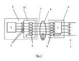
- a battery control device according to the invention is shown, with a first electronic unit 1 and a second electronic unit 2, which are connected to each other via a communication link.
- the second electronic unit 2 is formed by a cell monitoring unit which monitors and / or controls one or more battery cells of a battery system 7.
- the first electronic unit 1 is formed by a battery control unit.
- the communication link comprises a communication line 3, which is designed as a SPI bus connection with four lines.
- the communication connection can also comprise one or more control lines.
- Control lines are designed, for example, as enable / disable lines in order to activate or deactivate the electronics unit 2. As a result, for example, the quiescent current consumption of the electronic unit 2 can be reduced.
- a galvanic isolation 5 is arranged between the first electronic unit 1 and the communication line 3, wherein the galvanic separation 5 is designed, for example, as an optocoupler.
- the communication line 3 is protected by a shield 4 of electromagnetic interference.
- the shield 4 is connected at its two ends to the ground potential of the second electronic unit GND1.
- This ground potential GND1 is picked up by the second electronic unit 2 on the battery system 7 and extends over a ground line of the communication line 3 into a separate area 10, which is at the potential of the second electronic unit 2 and in a unit 8, which is the first electronic unit. 1 and the galvanic separation 5 includes, is formed.
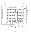
- Both between electrical isolation 5 and communication line 3, in the separate area 10 of the unit 8, as well as on the unit 9, which includes the second electronic unit 2, filter elements 6 are arranged.
- the filter elements 6 on both sides of the communication line 3 both ohmic resistors 6.1, and 6.2 capacitors, for example, filter capacitors of the data lines against the ground potential GND1, and inductors 6.3, such as ferrites.
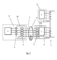
- a further second electronic unit 2 in particular a further cell monitoring unit, can be connected directly to a second electronic unit 2 so as to form a "daisy-chain".
- the communication of the further second electronic unit 2 with the first electronic unit 1 takes place in this embodiment indirectly via the communication link 3 in the Fig. 3 shown below second electronic unit 2.
- the ground potential GND1, GND2 of the two second electronic units 2 are connected to different potentials of the battery system.
- a plurality of second electronic units 2 can also be connected to the battery control unit via their own, direct communication line 3.
- Each communication line 3 is electromagnetically shielded by its own shielding 4, wherein each shielding 4 is connected at its two ends to the respective ground potential GND1 or GND3 of its second electronic unit 2.
- the invention thus makes it possible to equip a battery control device with a reliable and cost-effective connection between a first electronic unit and a second electronic unit even with longer communication paths.
Landscapes
- Engineering & Computer Science (AREA)
- Transportation (AREA)
- Life Sciences & Earth Sciences (AREA)
- Sustainable Development (AREA)
- Sustainable Energy (AREA)
- Power Engineering (AREA)
- Mechanical Engineering (AREA)
- Electrochemistry (AREA)
- General Chemical & Material Sciences (AREA)
- Chemical Kinetics & Catalysis (AREA)
- Chemical & Material Sciences (AREA)
- Charge And Discharge Circuits For Batteries Or The Like (AREA)
- Secondary Cells (AREA)
- Battery Mounting, Suspending (AREA)
Abstract
Description
Die vorliegende Erfindung betrifft eine Batteriesteuerungsvorrichtung mit einem mehrere Zellen umfassenden Batteriesystem, einer ersten Elektronikeinheit und einer zweiten Elektronikeinheit, wobei insbesondere das Massepotential der zweiten Elektronikeinheit an ein Potential des Batteriesystems angeschlossen ist und wobei die erste Elektronikeinheit und die zweite Elektronikeinheit zum Austausch von Informationen über eine Kommunikationsverbindung in Verbindung stehen.The present invention relates to a battery control device having a multi-cell battery system, a first electronic unit and a second electronic unit, wherein in particular the ground potential of the second electronic unit is connected to a potential of the battery system and wherein the first electronic unit and the second electronic unit for exchanging information about a Communication connection communicate.
Derartige Vorrichtungen werden beispielsweise für Elektro- und Hybridfahrzuge genutzt, um Hochvolt-Batteriesysteme, die üblicherweise eine Vielzahl von Batteriezellen umfassen, überwachen und steuern zu können. Hierzu kann eine zentrale erste Elektronikeinheit als Batteriesteuerungseinheit (Battery Management Unit, BMU) ausgeführt sein, die insbesondere den Gesamtzustand des Batteriesystems überwacht und beispielsweise einen Ladungsausgleich zwischen den Batteriezellen steuert. Zusätzlich werden häufig als zweite Elektronikeinheiten lokale Zellüberwachungseinheiten (Cell Supervisory Controler, CSC) eingesetzt, die beispielsweise für jede einzelne Batteriezelle oder für Gruppen von Batteriezellen Zustände wie Zellspannung und Temperatur erfassen und an die Batteriesteuerungseinheit kommunizieren. Die Massepotentiale der Zellüberwachungseinheiten können dabei mit dem Batteriesystem verbunden sein. Die Kommunikationsverbindung zwischen der Batteriesteuerungseinheit und den Zellüberwachungseinheiten ist üblicherweise als Controler Area Network-Bus (CAN-Bus) Verbindung ausgeführt, da dieser Verbindungstyp auch für längere Kommunikationswege eine zuverlässige Kommunikation gewährleistet. Jedoch sind für die Verwendung eines CAN-Busses sowohl auf Seite der Batteriesteuerungseinheit als auch auf Seite der Zellüberwachungseinheiten komplexe Sende-/Empfangsvorrichtungen zur Umsetzung des Protokolls erforderlich.Such devices are used, for example, for electric and hybrid vehicles to monitor and control high-voltage battery systems, which usually include a variety of battery cells. For this purpose, a central first electronic unit can be designed as a battery management unit (Battery Management Unit, BMU), which in particular monitors the overall state of the battery system and, for example, controls a charge balance between the battery cells. In addition, local cell monitoring units (Cell Supervisory Control, CSC) are often used as the second electronic units, for example, for each individual battery cell or groups of battery cells detect conditions such as cell voltage and temperature and communicate to the battery control unit. The ground potentials of the cell monitoring units can be connected to the battery system. The communication connection between the battery control unit and the cell monitoring units is usually designed as a Control Area Network Bus (CAN bus) connection, as this type of connection ensures reliable communication even for longer communication paths. However, for the use of a CAN bus both on the side of the battery control unit as well as on the side of the cell monitoring units complex transceiver devices to implement the protocol required.
Als Kommunikationsverbindung zwischen Elektronikeinheiten ist weiterhin der Serial Peripheral Interface-Bus (SPI-Bus) bekannt, der mit weniger Aufwand zu implementieren ist, sich jedoch zur Verbindung von räumlich weiter entfernt liegenden Elektronikeinheiten wenig eignet, da eine SPI-Bus-Verbindung anfällig für Störsignale, wie insbesondere Gleichtaktstörungen ist.As a communication link between electronic units further the Serial Peripheral Interface (SPI) bus is known, which is to implement with less effort, but is not suitable for the connection of remote electronic units, since an SPI bus connection prone to spurious signals in particular, common-mode noise is.
Eine Batterieüberwachungs- und Steuerungsvorrichtung ist aus der
Aus der
Eine Batteriemanagementvorrichtung ist auch aus der
Aus der
Es ist eine Aufgabe der Erfindung, Batteriesteuerungsvorrichtungen der genannten Art zu verbessern und insbesondere eine zuverlässige und kostengünstige Verbindung zwischen einer ersten Elektronikeinheit und einer zweiten Elektronikeinheit einer Batteriesteuerungsvorrichtung auch bei längeren Kommunikationswegen zu ermöglichen.It is an object of the invention to improve battery control devices of the type mentioned and in particular to enable a reliable and cost-effective connection between a first electronic unit and a second electronic unit of a battery control device even with longer communication paths.
Die Lösung der Aufgabe erfolgt durch eine Batteriesteuerungsvorrichtung mit einem mehrere Zellen umfassenden Batteriesystem, einer ersten Elektronikeinheit und einer zweiten Elektronikeinheit, wobei das Massepotential der zweiten Elektronikeinheit an ein Potential des Batteriesystems angeschlossen ist, wobei die erste Elektronikeinheit und die zweite Elektronikeinheit zum Austausch von Informationen über eine Kommunikationsverbindung in Verbindung stehen, wobei die Kommunikationsverbindung eine galvanische Trennung aufweist, wobei die Kommunikationsverbindung eine Kommunikationsleitung umfasst, wobei die Kommunikationsleitung zumindest abschnittsweise eine elektromagnetische Schirmung aufweist, wobei die elektromagnetische Schirmung an das Massepotential der zweiten Elektronikeinheit angeschlossen ist. Erfindungsgemäß ist zwischen der ersten Elektronikeinheit und der zweiten Elektronikeinheit eine Kommunikationsleitung vorgesehen, die elektromagnetisch abgeschirmt ausgeführt ist, und zusätzlich eine galvanische Trennung zwischen den Elektronikeinheiten. Die elektromagnetische Abschirmung ist so ausgeführt, dass die elektrische Schirmung der Kommunikationsleitung an das Massepotential der zweiten Elektronikeinheit angeschlossen ist, welches selbst wieder an ein Potential des Batteriesystems angeschlossen ist. Üblicherweise werden elektrische Abschirmungen mit der größten lokal verfügbaren elektrisch leitenden Masse verbunden, das wäre in einer Anordnung in einem Fahrzeug beispielsweise die Karosserie des Fahrzeuges. Es hat sich gezeigt, dass eine Anbindung der Schirmung an das galvanisch getrennte Potential der zweiten Elektronikeinheit, also beispielsweise einer Zellüberwachungseinheit, sowohl zu einer deutlich verbesserten Abschirmung der Kommunikationsleitung aufgrund niedrigerer Spannungsdifferenzen zwischen Kommunikationsleitung und Schirmung führt, als auch zu geringeren Störungen von der Kommunikationsleitung auf das Fahrzeug. Hierdurch ist es möglich auch über längere Verbindungswege eine ungestörte Kommunikation zwischen den Elektronikeinheiten über beispielsweise eine SPI-Bus Verbindung zu gewährleisten.The object is achieved by a battery control device having a multi-cell battery system, a first electronic unit and a second electronic unit, wherein the ground potential of the second electronic unit is connected to a potential of the battery system, wherein the first electronic unit and the second electronic unit for exchanging information about a communication connection are in communication, wherein the communication connection has a galvanic separation, wherein the communication connection comprises a communication line, the communication line at least partially having an electromagnetic shield, wherein the electromagnetic shield is connected to the ground potential of the second electronic unit. According to the invention a communication line is provided between the first electronic unit and the second electronic unit, which is designed to be electromagnetically shielded, and in addition a galvanic isolation between the electronic units. The electromagnetic shield is designed so that the electrical shield of the communication line is connected to the ground potential of the second electronic unit, which itself is connected to a potential of the battery system. Usually electrical shields are connected to the largest locally available electrically conductive mass, which would be in an arrangement in a vehicle, for example, the body of the vehicle. It has been shown that a connection of the shielding to the galvanically isolated potential of the second electronic unit, ie for example a cell monitoring unit, leads to a significantly improved shielding of the communication line due to lower voltage differences between the communication line and the shield, as well as to less interference from the communication line the vehicle. This makes it possible to ensure undisturbed communication between the electronic units via, for example, a SPI bus connection even over longer communication paths.
Vorteilhaft ist die die elektromagnetische Schirmung an beiden Enden an das Massepotential der zweiten Elektronikeinheit angeschlossen.Advantageously, the electromagnetic shield is connected at both ends to the ground potential of the second electronic unit.
In einer bevorzugten Ausführungsform sind die erste und die zweite Elektronikeinheit von einem ersten und zweiten Steuergerät gebildet.In a preferred embodiment, the first and the second electronic unit are formed by a first and second control unit.
Bevorzugt ist die erste Elektronikeinheit eine Batteriesteuerungseinheit (Battery Management Unit, BMU). Die Batteriesteuerungseinheit ist als übergeordnetes Kontroll- und Steuersystem für die Überwachung und Steuerung der Batteriezellen in ihrer Gesamtheit, also des gesamten Batteriesystems eingerichtet.Preferably, the first electronic unit is a battery management unit (Battery Management Unit, BMU). The battery control unit is as a superior control and monitoring system for monitoring and Control of the battery cells in their entirety, so set up the entire battery system.
Bevorzugt ist die zweite Elektronikeinheit eine Zellüberwachungseinheit (Cell Supervisory Controler, CSC), insbesondere eine Zellspannungsüberwachungseinheit. Die Zellüberwachungseinheit überwacht und/oder steuert eine Batterieeinheit, insbesondere eine einzelne Batteriezelle oder eine Gruppe von Batteriezellen und kommuniziert bevorzugt mit einer übergeordneten Batteriesteuerungseinheit.Preferably, the second electronic unit is a cell monitoring unit (Cell Supervisory Control, CSC), in particular a cell voltage monitoring unit. The cell monitoring unit monitors and / or controls a battery unit, in particular a single battery cell or a group of battery cells, and preferably communicates with a higher-level battery control unit.
Das Batteriesystem kann insbesondere ein Hochvolt-Batteriesystem eines Fahrzeuges sein, insbesondere zum Antrieb des Fahrzeugs.The battery system may in particular be a high-voltage battery system of a vehicle, in particular for driving the vehicle.
Die Energieversorgung der zweiten Elektronikeinheit kann über das Batteriesystem erfolgen. Die erste Elektronikeinheit kann beispielsweise von einem 12V-Bordnetz eines Fahrzeuges gespeist werden.The power supply of the second electronic unit can be done via the battery system. The first electronic unit can be powered, for example, by a 12V electrical system of a vehicle.
Bevorzugt ist die galvanische Trennung zwischen der ersten Elektronikeinheit und der Kommunikationsleitung angeordnet. Das Potential der zweiten Elektronikeinheit erstreckt sich über die Kommunikationsleitung bis in einen Bereich nahe der ersten Elektronikeinheit. Auf einer Baueinheit welche die erste Elektronikeinheit umfasst, kann ein gesonderter Bereich ausgebildet sein, der Komponenten auf dem Potential der zweiten Elektronikeinheit beherbergt. Der gesonderte Bereich ist dann von anderen Bereichen der Baueinheit und insbesondere von der ersten Elektronikeinheit galvanisch getrennt.Preferably, the galvanic isolation between the first electronic unit and the communication line is arranged. The potential of the second electronic unit extends over the communication line into a region near the first electronic unit. On a structural unit which comprises the first electronic unit, a separate area may be formed which houses components at the potential of the second electronic unit. The separate area is then galvanically isolated from other areas of the unit and in particular from the first electronic unit.
Bevorzugt ist die galvanische Trennung durch einen Optokoppler oder durch induktive oder kapazitive Übertragung gebildet.The galvanic isolation is preferably formed by an optocoupler or by inductive or capacitive transmission.
Filterelemente sind bevorzugt zwischen Kommunikationsleitung und erster Elektronikeinheit und/oder zwischen Kommunikationsleitung und zweiter Elektronikeinheit angeordnet. Besonders bevorzugt sind Filterelemente, vor allem bei bidirektionalen Kommunikationsverbindungen, beiderseits der Kommunikationsleitung angeordnet. Durch geeignete Filterelemente werden vor allem Spannungsänderungen und Stromänderungen in der Kommunikationsleitung gedämpft und so Störungen benachbarter Kommunikationsleitungen vermindert.Filter elements are preferably arranged between the communication line and the first electronic unit and / or between the communication line and the second electronic unit. Particularly preferred filter elements, especially in bidirectional communication links, arranged on both sides of the communication line. Above all, voltage changes and current changes in the communication line are attenuated by suitable filter elements, thus reducing disturbances of adjacent communication lines.
Die Filterelemente können Längswiderstände und Ableitkondensatoren umfassen, die insbesondere beiderseits der Schirmung angeordnet sind und die Tiefpassfilter bilden können.The filter elements may include series resistors and bypass capacitors, which are arranged in particular on both sides of the shield and can form the low-pass filter.
Die Filterelemente können auch Induktivitäten umfassen, die ebenfalls bevorzugt beiderseits der Schirmung angeordnet sind, wodurch Gleichtaktstörungen in der Kommunikationsleitung verringert werden.The filter elements may also include inductors, which are also preferably disposed on both sides of the shield, thereby reducing common mode noise in the communication line.
Bevorzugt erfolgt der Austausch von Informationen über die Kommunikationsverbindung über einen Serial Peripheral Interface-Bus (SPI).Preferably, the exchange of information takes place via the communication connection via a Serial Peripheral Interface Bus (SPI).
Bevorzugt weist die Kommunikationsleitung eine Länge von mehr als 10 cm, insbesondere mehr als 20 cm, insbesondere mehr als 50 cm auf. Dadurch ist eine räumlich getrennte Anordnung der ersten von der zweiten Elektronikeinheit möglich, eine sichere Kommunikationsverbindung zwischen den Elektronikeinheiten jedoch auch über größere Distanzen gewährleistet.The communication line preferably has a length of more than 10 cm, in particular more than 20 cm, in particular more than 50 cm. As a result, a spatially separated arrangement of the first of the second electronic unit is possible, but ensures a secure communication connection between the electronic units but also over greater distances.
Nach einer bevorzugten Ausführungsform umfasst die Batteriesteuerungsvorrichtung mehrere zweite Elektronikeinheiten, also insbesondere mehrere Zellüberwachungseinheiten, die zumindest teilweise untereinander verbunden sind, wobei zumindest eine jedoch bevorzugt nicht alle der zweiten Elektronikeinheiten mit der ersten Elektronikeinheit in direkter Kommunikationsverbindung stehen. Die zweiten Elektronikeinheiten können sog. "Daisy-Chains" bilden, wobei nur eine oder manche der zweiten Elektronikeinheiten mit der, üblicherweise einzigen, ersten Elektronikeinheit verbunden sind. Die Verbindung der zweiten Elektronikeinheiten untereinander erfolgt bevorzugt potentialgetrennt, beispielsweise durch Kapazitäten in den Verbindungsleitungen, und verwendet bevorzugt ein differentielles Bus-System.According to a preferred embodiment, the battery control device comprises a plurality of second electronic units, that is to say in particular a plurality of cell monitoring units which are at least partially interconnected are connected, wherein at least one but preferably not all of the second electronic units are in direct communication with the first electronic unit. The second electronic units can form so-called "daisy chains", wherein only one or some of the second electronic units are connected to the, usually single, first electronic unit. The connection of the second electronic units with each other is preferably electrically isolated, for example by capacitances in the connecting lines, and preferably uses a differential bus system.
Wenn die Batteriesteuerungsvorrichtung mehrere zweite Elektronikeinheiten umfasst, stehen bevorzugt zumindest zwei der zweiten Elektronikeinheiten mit der ersten Elektronikeinheit in direkter Kommunikationsverbindung, wobei diese direkten Kommunikationsverbindungen wie oben beschrieben ausgeführt sein können, also insbesondere jeweils galvanisch getrennt, jeweils abgeschirmt und/oder jeweils mit Filtern ausgestattet sein können. Der Einsatz mehrerer, mit der ersten Elektronikeinheit direkt verbundener, zweiter Elektronikeinheiten ist vor allem vorteilhaft, um trotz erforderlicher Störungsminderungsmaßnahmen, wie Filter, und der damit verbundenen niedrigen Datenübertragungsrate, eine insgesamt hohe Datenübertragungsrate zwischen erster Elektronikeinheit und zweiten Elektronikeinheiten sicher zu stellen.If the battery control device comprises a plurality of second electronic units, preferably at least two of the second electronic units are in direct communication connection with the first electronic unit, whereby these direct communication connections can be designed as described above, ie in particular each galvanically separated, each shielded and / or each equipped with filters can. The use of several, directly connected to the first electronic unit, second electronic units is particularly advantageous to ensure a total high data transmission rate between the first electronic unit and second electronic units despite required mitigation measures, such as filters, and the associated low data transmission rate.
Die Massepotentiale der zweiten Elektronikeinheiten sind bevorzugt an verschieden hohe Potentiale des Batteriesystems angeschlossen, so dass die Massepotentiale der zweiten Elektronikeinheiten voneinander verschieden sind. Hierdurch weisen auch die Schirmungen der verschiedenen Kommunikationsleitungen unterschiedliche Massepotentiale auf. Durch die Ausführung der Schirmungen mit jeweils lokal angepassten Massenpotentialen wird eine optimale Abschirmung von elektromagnetischen Störungen erreicht.The ground potentials of the second electronic units are preferably connected to different high potentials of the battery system, so that the ground potentials of the second electronic units are different from each other. As a result, the shields of the various communication lines also have different ground potentials. Due to the design of the shields, each with locally adapted mass potentials Optimal shielding of electromagnetic interference is achieved.
Weiterbildungen der Erfindung sind in den abhängigen Ansprüchen, der Beschreibung sowie den beigefügten Zeichnungen angegeben.Further developments of the invention are specified in the dependent claims, the description and the accompanying drawings.
Die Erfindung wird im Folgenden beispielhaft unter Bezugnahme auf die Zeichnungen beschrieben.
- Fig. 1
- ist eine schematische Darstellung einer erfindungsgemäßen Batteriesteuerungsvorrichtung.
- Fig. 2
- ist eine schematische Darstellung gem.
Fig. 1 , mit zusätzlichen Details der Batteriesteuerungsvorrichtung. - Fig. 3 bis Fig. 5
- sind schematische Darstellungen von weiteren erfindungsgemäßen Batteriesteuerungsvorrichtungen.
- Fig. 1
- is a schematic representation of a battery control device according to the invention.
- Fig. 2
- is a schematic representation acc.
Fig. 1 , with additional details of the battery control device. - FIG. 3 to FIG. 5
- are schematic representations of other battery control devices according to the invention.
In
Wie in der
Wie in
Wie aus den Ausführungsbeispielen der
Die Erfindung ermöglicht somit eine Batteriesteuerungsvorrichtung mit einer zuverlässigen und kostengünstigen Verbindung zwischen einer ersten Elektronikeinheit und einer zweiten Elektronikeinheit auch bei längeren Kommunikationswegen auszustatten.The invention thus makes it possible to equip a battery control device with a reliable and cost-effective connection between a first electronic unit and a second electronic unit even with longer communication paths.
- 11
- erste Elektronikeinheitfirst electronic unit
- 22
- zweite Elektronikeinheitsecond electronic unit
- 33
- Kommunikationsleitungcommunication line
- 44
- Schirmungshielding
- 55
- galvanische Trennunggalvanic isolation
- 66
- Filterelementefilter elements
- 6.16.1
- Widerstandresistance
- 6.26.2
- Kapazitätcapacity
- 6.36.3
- Induktivitätinductance
- 77
- Batteriesystembattery system
- 88th
- Baueinheitunit
- 99
- Baueinheitunit
- 1010
- gesonderter Bereichseparate area
- GND1, GND2, GND3, GND4GND1, GND2, GND3, GND4
- Massepotentialeground potentials
- SCLK, MOSI, MISO, SSSCLK, MOSI, MISO, SS
- Leitungen der SPI-Bus VerbindungLines of the SPI bus connection
Claims (14)
dadurch gekennzeichnet,
dass die Kommunikationsleitung (3) zumindest abschnittsweise eine elektromagnetische Schirmung (4) aufweist,
wobei die elektromagnetische Schirmung (4) an das Massepotential (GND1) der zweiten Elektronikeinheit (2) angeschlossen ist.Battery control device comprising a battery system (7) comprising several cells, a first electronic unit (1) and a second electronic unit (2), wherein the ground potential (GND1) of the second electronic unit (2) is connected to a potential of the battery system (7) the first electronic unit (1) and the second electronic unit (2) are in communication for exchanging information via a communication connection, the communication connection having a galvanic isolation (5), the communication connection comprising a communication line (3),
characterized,
that the communication line (3) has at least in sections an electromagnetic shielding (4),
wherein the electromagnetic shield (4) is connected to the ground potential (GND1) of the second electronic unit (2).
dadurch gekennzeichnet, dass die erste Elektronikeinheit (1) eine Batteriesteuerungseinheit ist.Battery control device according to claim 1,
characterized in that the first electronic unit (1) is a battery control unit.
dadurch gekennzeichnet, dass die zweite Elektronikeinheit (2) eine Zellüberwachungseinheit ist.Battery control device according to claim 1 or 2,
characterized in that the second electronic unit (2) is a cell monitoring unit.
dadurch gekennzeichnet, dass die galvanische Trennung (5) zwischen der ersten Elektronikeinheit (1) und der Kommunikationsleitung (3) angeordnet ist.Battery control device according to at least one of the preceding claims,
characterized in that the electrical isolation (5) between the first electronic unit (1) and the communication line (3) is arranged.
dadurch gekennzeichnet, dass die galvanische Trennung (5) durch einen Optokoppler oder durch induktive oder kapazitive Übertragung gebildet ist.Battery control device according to at least one of the preceding claims,
characterized in that the galvanic separation (5) is formed by an optocoupler or by inductive or capacitive transmission.
dadurch gekennzeichnet, dass sich das Massepotential (GND1) der zweiten Elektronikeinheit (2) über die Kommunikationsleitung (3) bis in einen gesonderter Bereich (10) erstreckt, der auf einer Baueinheit (8) ausgebildet ist, wobei die Baueinheit (8) die erste Elektronikeinheit (1) umfasst, wobei der gesonderte Bereich (10) insbesondere Komponenten mit dem Massepotential (GND1) der zweiten Elektronikeinheit (2) beherbergt.Battery control device according to at least one of the preceding claims,
characterized in that the ground potential (GND1) of the second electronic unit (2) extends over the communication line (3) into a separate area (10) which is formed on a structural unit (8), wherein the structural unit (8) the first Electronic unit (1), wherein the separate area (10) in particular houses components with the ground potential (GND1) of the second electronic unit (2).
dadurch gekennzeichnet, dass Filterelemente (6) zwischen Kommunikationsleitung (3) und erster Elektronikeinheit (1) und/oder zwischen Kommunikationsleitung (3) und zweiter Elektronikeinheit (2) angeordnet sind.Battery control device according to at least one of the preceding claims,
characterized in that filter elements (6) between the communication line (3) and the first electronic unit (1) and / or between the communication line (3) and the second electronic unit (2) are arranged.
dadurch gekennzeichnet, dass die Filterelemente (6) beiderseits der Schirmung (4) Längswiderstände (6.1) , und Ableitkondensatoren (6.2) umfassen.Battery control device according to claim 7,
characterized in that the filter elements (6) comprise on both sides of the shield (4) series resistors (6.1), and bypass capacitors (6.2).
dadurch gekennzeichnet, dass die Filterelemente (6) beiderseits der Schirmung (4) Induktivitäten (6.3) umfassen.Battery control device according to claim 7 or 8,
characterized in that the filter elements (6) comprise inductances (6.3) on both sides of the shield (4).
dadurch gekennzeichnet, dass der Austausch von Informationen über die Kommunikationsverbindung über einen Serial Peripheral Interface-Bus (SPI) erfolgt.Battery control device according to at least one of the preceding claims,
characterized in that the exchange of information via the communication connection via a Serial Peripheral Interface Bus (SPI) takes place.
dadurch gekennzeichnet, dass die Kommunikationsleitung (3) eine Länge von mehr als 10 cm, insbesondere mehr als 20 cm, insbesondere mehr als 50 cm aufweist.Battery control device according to at least one of the preceding claims,
characterized in that the communication line (3) has a length of more than 10 cm, in particular more than 20 cm, in particular more than 50 cm.
dadurch gekennzeichnet, dass die Batteriesteuerungsvorrichtung mehrere zweite Elektronikeinheiten (2) umfasst, die zumindest teilweise untereinander verbunden sind, wobei zumindest eine jedoch bevorzugt nicht alle der zweiten Elektronikeinheiten (2) mit der ersten Elektronikeinheit (1) in direkter Kommunikationsverbindung mit Merkmalen nach zumindest einem der vorstehenden Ansprüche stehen.Battery control device according to at least one of the preceding claims,
characterized in that the battery control device comprises a plurality of second electronic units (2) at least partially interconnected, at least one but preferably not all of the second electronic units (2) being in direct communication with the first electronic unit (1) in communication with features of at least one of preceding claims.
dadurch gekennzeichnet, dass die Batteriesteuerungsvorrichtung mehrere zweite Elektronikeinheiten (2) umfasst, wobei zumindest zwei der zweiten Elektronikeinheiten (2) mit der ersten Elektronikeinheit (1) in direkter Kommunikationsverbindung mit Merkmalen nach zumindest einem der vorstehenden Ansprüche stehen.Battery control device according to at least one of the preceding claims,
characterized in that the battery control device comprises a plurality of second electronic units (2), wherein at least two of the second electronic units (2) with the first electronic unit (1) are in direct communication connection with features according to at least one of the preceding claims.
dadurch gekennzeichnet, dass die Massepotentiale (GND1, GND2, GND3, GND4) der zweiten Elektronikeinheiten (2) an verschiedene Potentiale des Batteriesystems (7) angeschlossen sind.Battery control device according to one of claims 12 or 13,
characterized in that the ground potentials (GND1, GND2, GND3, GND4) of the second electronic units (2) are connected to different potentials of the battery system (7).
Priority Applications (1)
| Application Number | Priority Date | Filing Date | Title |
|---|---|---|---|
| EP13152533.9A EP2632019B1 (en) | 2012-02-24 | 2013-01-24 | Battery control device |
Applications Claiming Priority (2)
| Application Number | Priority Date | Filing Date | Title |
|---|---|---|---|
| EP12156846.3A EP2632017A1 (en) | 2012-02-24 | 2012-02-24 | Battery control device |
| EP13152533.9A EP2632019B1 (en) | 2012-02-24 | 2013-01-24 | Battery control device |
Publications (2)
| Publication Number | Publication Date |
|---|---|
| EP2632019A1 true EP2632019A1 (en) | 2013-08-28 |
| EP2632019B1 EP2632019B1 (en) | 2015-04-08 |
Family
ID=47561494
Family Applications (2)
| Application Number | Title | Priority Date | Filing Date |
|---|---|---|---|
| EP12156846.3A Withdrawn EP2632017A1 (en) | 2012-02-24 | 2012-02-24 | Battery control device |
| EP13152533.9A Active EP2632019B1 (en) | 2012-02-24 | 2013-01-24 | Battery control device |
Family Applications Before (1)
| Application Number | Title | Priority Date | Filing Date |
|---|---|---|---|
| EP12156846.3A Withdrawn EP2632017A1 (en) | 2012-02-24 | 2012-02-24 | Battery control device |
Country Status (3)
| Country | Link |
|---|---|
| US (1) | US9231233B2 (en) |
| EP (2) | EP2632017A1 (en) |
| CN (1) | CN103296711B (en) |
Families Citing this family (1)
| Publication number | Priority date | Publication date | Assignee | Title |
|---|---|---|---|---|
| US10992144B2 (en) * | 2017-05-17 | 2021-04-27 | Galley Power LLC | Battery balancing and current control with bypass circuit for load switch |
Citations (4)
| Publication number | Priority date | Publication date | Assignee | Title |
|---|---|---|---|---|
| US5850351A (en) | 1996-04-25 | 1998-12-15 | General Motors Corporation | Distributed management apparatus for battery pack |
| US20070182377A1 (en) | 2005-12-29 | 2007-08-09 | Geert Vandensande | Method and system for monitoring battery stacks |
| US20100173180A1 (en) | 2009-01-06 | 2010-07-08 | Guoxing Li | Battery management system |
| DE102010016175A1 (en) | 2009-04-09 | 2011-08-04 | Ford Global Technologies, LLC, Mich. | Battery monitoring and control device and method for its use |
Family Cites Families (19)
| Publication number | Priority date | Publication date | Assignee | Title |
|---|---|---|---|---|
| US4232259A (en) * | 1976-12-28 | 1980-11-04 | Yokogawa Electric Works, Ltd. | Servo-system |
| EP0533971A1 (en) * | 1991-09-24 | 1993-03-31 | Siemens Aktiengesellschaft | Interface circuit |
| JPH07202618A (en) * | 1993-12-28 | 1995-08-04 | Rohm Co Ltd | Chip-shaped filter |
| US6230105B1 (en) * | 1999-01-22 | 2001-05-08 | Bolt, Inc. | Transfer impedance measurement instrument system |
| US6346865B1 (en) * | 1999-04-29 | 2002-02-12 | Delphi Technologies, Inc. | EMI/RFI filter including a ferroelectric/ferromagnetic composite |
| US6782131B2 (en) * | 1999-12-29 | 2004-08-24 | Honeywell International Inc. | System, method and apparatus for pattern recognition with application to symbol recognition and regeneration for a display |
| US6640273B1 (en) * | 2000-01-05 | 2003-10-28 | Tektronix, Inc. | Apparatus for data bus expansion between two instrument chassis |
| US6449166B1 (en) * | 2000-08-24 | 2002-09-10 | High Connection Density, Inc. | High capacity memory module with higher density and improved manufacturability |
| JP4605952B2 (en) * | 2001-08-29 | 2011-01-05 | 株式会社日立製作所 | Power storage device and control method thereof |
| US6719591B1 (en) * | 2003-03-28 | 2004-04-13 | Cheng Chun Chang | SATA interface relay connector and its application |
| WO2004109896A2 (en) * | 2003-06-04 | 2004-12-16 | International Rectifier Corporation | Active emi filter having no inductive current sensing device |
| US20060212838A1 (en) * | 2005-02-09 | 2006-09-21 | Checksum, Llc | System and apparatus for in-system programming |
| US7872430B2 (en) * | 2005-11-18 | 2011-01-18 | Cree, Inc. | Solid state lighting panels with variable voltage boost current sources |
| US7349813B2 (en) * | 2006-05-16 | 2008-03-25 | Dresser, Inc. | Fault tolerant power system architecture for fluid flow measurement systems |
| US20100058276A1 (en) * | 2007-09-11 | 2010-03-04 | Andreas Felder | Method for the integration of an integrated circuit into a standardized software architecture for embedded systems |
| TWI413790B (en) * | 2010-02-24 | 2013-11-01 | Tatung Co | Measurement correcting system and method thereof |
| JP5530269B2 (en) * | 2010-06-28 | 2014-06-25 | ラピスセミコンダクタ株式会社 | Communication interface device and communication method |
| US8626083B2 (en) * | 2011-05-16 | 2014-01-07 | Blackberry Limited | Method and apparatus for tuning a communication device |
| US8643405B2 (en) * | 2011-11-30 | 2014-02-04 | Mcci Corporation | Passive capture adapter circuit for sensing signals of a high-speed circuit |
-
2012
- 2012-02-24 EP EP12156846.3A patent/EP2632017A1/en not_active Withdrawn
-
2013
- 2013-01-24 EP EP13152533.9A patent/EP2632019B1/en active Active
- 2013-02-22 CN CN201310056078.0A patent/CN103296711B/en active Active
- 2013-02-25 US US13/775,306 patent/US9231233B2/en active Active
Patent Citations (4)
| Publication number | Priority date | Publication date | Assignee | Title |
|---|---|---|---|---|
| US5850351A (en) | 1996-04-25 | 1998-12-15 | General Motors Corporation | Distributed management apparatus for battery pack |
| US20070182377A1 (en) | 2005-12-29 | 2007-08-09 | Geert Vandensande | Method and system for monitoring battery stacks |
| US20100173180A1 (en) | 2009-01-06 | 2010-07-08 | Guoxing Li | Battery management system |
| DE102010016175A1 (en) | 2009-04-09 | 2011-08-04 | Ford Global Technologies, LLC, Mich. | Battery monitoring and control device and method for its use |
Also Published As
| Publication number | Publication date |
|---|---|
| US20130224534A1 (en) | 2013-08-29 |
| CN103296711B (en) | 2016-03-02 |
| EP2632017A1 (en) | 2013-08-28 |
| US9231233B2 (en) | 2016-01-05 |
| CN103296711A (en) | 2013-09-11 |
| EP2632019B1 (en) | 2015-04-08 |
Similar Documents
| Publication | Publication Date | Title |
|---|---|---|
| EP3818605B1 (en) | Vehicle electrical system for a vehicle, and vehicle | |
| EP1965482B1 (en) | ASI network for areas subject to explosive risk | |
| DE102014200111A1 (en) | A battery management system for monitoring and controlling the operation of a battery and battery system having such a battery management system | |
| DE102014202626A1 (en) | Battery management system for a battery with multiple battery cells and method | |
| DE102014101391B4 (en) | Capacitive communication layer for a cell-integrated battery management system | |
| EP2181480B2 (en) | Battery or rechargeable-battery pack | |
| DE102014200096A1 (en) | A battery management system for monitoring and controlling the operation of a battery and battery system having such a battery management system | |
| EP2865068B1 (en) | Batterymanagementsystem with improved robustness against negative voltages | |
| WO2013064322A2 (en) | Battery management unit having a plurality of monitoring ic chips | |
| DE102013012615A1 (en) | Circuit module for separating subnetworks of a multi-voltage vehicle electrical system | |
| DE112017000622T5 (en) | Circuit body for a vehicle | |
| DE102018133657A1 (en) | BASIC MODULE AND FUNCTIONAL MODULE FOR A CONTROL CABINET SYSTEM AND CONTROL CABINET SYSTEM | |
| DE102005043907B4 (en) | Semiconductor circuits and transmission devices for fail-safe communication in motor vehicles | |
| EP2664158B1 (en) | Battery management unit comprising a plurality of monitoring units | |
| EP2852997B1 (en) | Conditioning device and method for conditioning a data channel of a cell of an electric energy accumulator | |
| EP2698861B1 (en) | HV battery system for a motor vehicle | |
| EP2632019B1 (en) | Battery control device | |
| DE102013206829A1 (en) | Method and electronic component for transmitting control signals between different on-board networks in a motor vehicle | |
| EP2803109B1 (en) | Battery arrangement for a motor vehicle | |
| DE102019209072A1 (en) | Battery control arrangement and method for operating a battery control arrangement | |
| DE102022110037A1 (en) | Charging system and retrofit kit for a charging system for bidirectional charging of an electric vehicle battery | |
| DE102017006979A1 (en) | High-voltage arrangement for a motor vehicle with signal transmission via a high-voltage screen | |
| WO2012110538A1 (en) | Communications system, especially for a motor vehicle, comprising an electronic circuit that can be controlled by an arithmetic unit | |
| EP3586422B1 (en) | Two-voltage battery | |
| DE102018219739A1 (en) | Battery cell, battery module control unit and battery module |
Legal Events
| Date | Code | Title | Description |
|---|---|---|---|
| PUAI | Public reference made under article 153(3) epc to a published international application that has entered the european phase |
Free format text: ORIGINAL CODE: 0009012 |
|
| 17P | Request for examination filed |
Effective date: 20130513 |
|
| AK | Designated contracting states |
Kind code of ref document: A1 Designated state(s): AL AT BE BG CH CY CZ DE DK EE ES FI FR GB GR HR HU IE IS IT LI LT LU LV MC MK MT NL NO PL PT RO RS SE SI SK SM TR |
|
| AX | Request for extension of the european patent |
Extension state: BA ME |
|
| REG | Reference to a national code |
Ref country code: DE Ref legal event code: R079 Ref document number: 502013000522 Country of ref document: DE Free format text: PREVIOUS MAIN CLASS: H02J0007000000 Ipc: H01M0002000000 |
|
| GRAP | Despatch of communication of intention to grant a patent |
Free format text: ORIGINAL CODE: EPIDOSNIGR1 |
|
| RIC1 | Information provided on ipc code assigned before grant |
Ipc: B60L 11/18 20060101ALI20141218BHEP Ipc: H01M 2/00 20060101AFI20141218BHEP |
|
| INTG | Intention to grant announced |
Effective date: 20150112 |
|
| GRAS | Grant fee paid |
Free format text: ORIGINAL CODE: EPIDOSNIGR3 |
|
| GRAA | (expected) grant |
Free format text: ORIGINAL CODE: 0009210 |
|
| AK | Designated contracting states |
Kind code of ref document: B1 Designated state(s): AL AT BE BG CH CY CZ DE DK EE ES FI FR GB GR HR HU IE IS IT LI LT LU LV MC MK MT NL NO PL PT RO RS SE SI SK SM TR |
|
| RAP1 | Party data changed (applicant data changed or rights of an application transferred) |
Owner name: MAGNA STEYR BATTERY SYSTEMS GMBH & CO OG |
|
| REG | Reference to a national code |
Ref country code: GB Ref legal event code: FG4D Free format text: NOT ENGLISH |
|
| REG | Reference to a national code |
Ref country code: CH Ref legal event code: EP |
|
| REG | Reference to a national code |
Ref country code: IE Ref legal event code: FG4D Free format text: LANGUAGE OF EP DOCUMENT: GERMAN |
|
| REG | Reference to a national code |
Ref country code: DE Ref legal event code: R096 Ref document number: 502013000522 Country of ref document: DE Effective date: 20150513 |
|
| REG | Reference to a national code |
Ref country code: AT Ref legal event code: REF Ref document number: 721138 Country of ref document: AT Kind code of ref document: T Effective date: 20150515 |
|
| REG | Reference to a national code |
Ref country code: DE Ref legal event code: R082 Ref document number: 502013000522 Country of ref document: DE Representative=s name: GULDE & PARTNER PATENT- UND RECHTSANWALTSKANZL, DE Ref country code: DE Ref legal event code: R081 Ref document number: 502013000522 Country of ref document: DE Owner name: SAMSUNG SDI CO., LTD., YONGIN-SI, KR Free format text: FORMER OWNER: MAGNA STEYR BATTERY SYSTEMS GMBH & CO OG, ZETTLING, AT |
|
| REG | Reference to a national code |
Ref country code: NL Ref legal event code: VDEP Effective date: 20150408 |
|
| RAP2 | Party data changed (patent owner data changed or rights of a patent transferred) |
Owner name: SAMSUNG SDI CO., LTD. |
|
| REG | Reference to a national code |
Ref country code: LT Ref legal event code: MG4D |
|
| PG25 | Lapsed in a contracting state [announced via postgrant information from national office to epo] |
Ref country code: NL Free format text: LAPSE BECAUSE OF FAILURE TO SUBMIT A TRANSLATION OF THE DESCRIPTION OR TO PAY THE FEE WITHIN THE PRESCRIBED TIME-LIMIT Effective date: 20150408 |
|
| PG25 | Lapsed in a contracting state [announced via postgrant information from national office to epo] |
Ref country code: FI Free format text: LAPSE BECAUSE OF FAILURE TO SUBMIT A TRANSLATION OF THE DESCRIPTION OR TO PAY THE FEE WITHIN THE PRESCRIBED TIME-LIMIT Effective date: 20150408 Ref country code: HR Free format text: LAPSE BECAUSE OF FAILURE TO SUBMIT A TRANSLATION OF THE DESCRIPTION OR TO PAY THE FEE WITHIN THE PRESCRIBED TIME-LIMIT Effective date: 20150408 Ref country code: ES Free format text: LAPSE BECAUSE OF FAILURE TO SUBMIT A TRANSLATION OF THE DESCRIPTION OR TO PAY THE FEE WITHIN THE PRESCRIBED TIME-LIMIT Effective date: 20150408 Ref country code: NO Free format text: LAPSE BECAUSE OF FAILURE TO SUBMIT A TRANSLATION OF THE DESCRIPTION OR TO PAY THE FEE WITHIN THE PRESCRIBED TIME-LIMIT Effective date: 20150708 Ref country code: LT Free format text: LAPSE BECAUSE OF FAILURE TO SUBMIT A TRANSLATION OF THE DESCRIPTION OR TO PAY THE FEE WITHIN THE PRESCRIBED TIME-LIMIT Effective date: 20150408 Ref country code: PT Free format text: LAPSE BECAUSE OF FAILURE TO SUBMIT A TRANSLATION OF THE DESCRIPTION OR TO PAY THE FEE WITHIN THE PRESCRIBED TIME-LIMIT Effective date: 20150810 |
|
| PG25 | Lapsed in a contracting state [announced via postgrant information from national office to epo] |
Ref country code: IS Free format text: LAPSE BECAUSE OF FAILURE TO SUBMIT A TRANSLATION OF THE DESCRIPTION OR TO PAY THE FEE WITHIN THE PRESCRIBED TIME-LIMIT Effective date: 20150808 Ref country code: RS Free format text: LAPSE BECAUSE OF FAILURE TO SUBMIT A TRANSLATION OF THE DESCRIPTION OR TO PAY THE FEE WITHIN THE PRESCRIBED TIME-LIMIT Effective date: 20150408 Ref country code: GR Free format text: LAPSE BECAUSE OF FAILURE TO SUBMIT A TRANSLATION OF THE DESCRIPTION OR TO PAY THE FEE WITHIN THE PRESCRIBED TIME-LIMIT Effective date: 20150709 Ref country code: LV Free format text: LAPSE BECAUSE OF FAILURE TO SUBMIT A TRANSLATION OF THE DESCRIPTION OR TO PAY THE FEE WITHIN THE PRESCRIBED TIME-LIMIT Effective date: 20150408 |
|
| REG | Reference to a national code |
Ref country code: FR Ref legal event code: PLFP Year of fee payment: 4 |
|
| REG | Reference to a national code |
Ref country code: DE Ref legal event code: R097 Ref document number: 502013000522 Country of ref document: DE |
|
| PG25 | Lapsed in a contracting state [announced via postgrant information from national office to epo] |
Ref country code: DK Free format text: LAPSE BECAUSE OF FAILURE TO SUBMIT A TRANSLATION OF THE DESCRIPTION OR TO PAY THE FEE WITHIN THE PRESCRIBED TIME-LIMIT Effective date: 20150408 Ref country code: EE Free format text: LAPSE BECAUSE OF FAILURE TO SUBMIT A TRANSLATION OF THE DESCRIPTION OR TO PAY THE FEE WITHIN THE PRESCRIBED TIME-LIMIT Effective date: 20150408 |
|
| PLBE | No opposition filed within time limit |
Free format text: ORIGINAL CODE: 0009261 |
|
| STAA | Information on the status of an ep patent application or granted ep patent |
Free format text: STATUS: NO OPPOSITION FILED WITHIN TIME LIMIT |
|
| PG25 | Lapsed in a contracting state [announced via postgrant information from national office to epo] |
Ref country code: RO Free format text: LAPSE BECAUSE OF NON-PAYMENT OF DUE FEES Effective date: 20150408 Ref country code: SK Free format text: LAPSE BECAUSE OF FAILURE TO SUBMIT A TRANSLATION OF THE DESCRIPTION OR TO PAY THE FEE WITHIN THE PRESCRIBED TIME-LIMIT Effective date: 20150408 Ref country code: CZ Free format text: LAPSE BECAUSE OF FAILURE TO SUBMIT A TRANSLATION OF THE DESCRIPTION OR TO PAY THE FEE WITHIN THE PRESCRIBED TIME-LIMIT Effective date: 20150408 Ref country code: PL Free format text: LAPSE BECAUSE OF FAILURE TO SUBMIT A TRANSLATION OF THE DESCRIPTION OR TO PAY THE FEE WITHIN THE PRESCRIBED TIME-LIMIT Effective date: 20150408 |
|
| 26N | No opposition filed |
Effective date: 20160111 |
|
| REG | Reference to a national code |
Ref country code: GB Ref legal event code: 732E Free format text: REGISTERED BETWEEN 20160218 AND 20160224 |
|
| REG | Reference to a national code |
Ref country code: GB Ref legal event code: 732E Free format text: REGISTERED BETWEEN 20160225 AND 20160302 |
|
| PG25 | Lapsed in a contracting state [announced via postgrant information from national office to epo] |
Ref country code: IT Free format text: LAPSE BECAUSE OF FAILURE TO SUBMIT A TRANSLATION OF THE DESCRIPTION OR TO PAY THE FEE WITHIN THE PRESCRIBED TIME-LIMIT Effective date: 20150408 |
|
| REG | Reference to a national code |
Ref country code: FR Ref legal event code: TP Owner name: SAMSUNG SDI CO., LTD., KR Effective date: 20160420 |
|
| PG25 | Lapsed in a contracting state [announced via postgrant information from national office to epo] |
Ref country code: SI Free format text: LAPSE BECAUSE OF FAILURE TO SUBMIT A TRANSLATION OF THE DESCRIPTION OR TO PAY THE FEE WITHIN THE PRESCRIBED TIME-LIMIT Effective date: 20150408 Ref country code: BE Free format text: LAPSE BECAUSE OF NON-PAYMENT OF DUE FEES Effective date: 20160131 |
|
| PG25 | Lapsed in a contracting state [announced via postgrant information from national office to epo] |
Ref country code: LU Free format text: LAPSE BECAUSE OF FAILURE TO SUBMIT A TRANSLATION OF THE DESCRIPTION OR TO PAY THE FEE WITHIN THE PRESCRIBED TIME-LIMIT Effective date: 20160124 |
|
| REG | Reference to a national code |
Ref country code: CH Ref legal event code: PL |
|
| PG25 | Lapsed in a contracting state [announced via postgrant information from national office to epo] |
Ref country code: MC Free format text: LAPSE BECAUSE OF FAILURE TO SUBMIT A TRANSLATION OF THE DESCRIPTION OR TO PAY THE FEE WITHIN THE PRESCRIBED TIME-LIMIT Effective date: 20150408 |
|
| PG25 | Lapsed in a contracting state [announced via postgrant information from national office to epo] |
Ref country code: LI Free format text: LAPSE BECAUSE OF NON-PAYMENT OF DUE FEES Effective date: 20160131 Ref country code: CH Free format text: LAPSE BECAUSE OF NON-PAYMENT OF DUE FEES Effective date: 20160131 |
|
| REG | Reference to a national code |
Ref country code: IE Ref legal event code: MM4A |
|
| REG | Reference to a national code |
Ref country code: FR Ref legal event code: PLFP Year of fee payment: 5 |
|
| PG25 | Lapsed in a contracting state [announced via postgrant information from national office to epo] |
Ref country code: IE Free format text: LAPSE BECAUSE OF NON-PAYMENT OF DUE FEES Effective date: 20160124 |
|
| PG25 | Lapsed in a contracting state [announced via postgrant information from national office to epo] |
Ref country code: SE Free format text: LAPSE BECAUSE OF FAILURE TO SUBMIT A TRANSLATION OF THE DESCRIPTION OR TO PAY THE FEE WITHIN THE PRESCRIBED TIME-LIMIT Effective date: 20150408 |
|
| PG25 | Lapsed in a contracting state [announced via postgrant information from national office to epo] |
Ref country code: MT Free format text: LAPSE BECAUSE OF FAILURE TO SUBMIT A TRANSLATION OF THE DESCRIPTION OR TO PAY THE FEE WITHIN THE PRESCRIBED TIME-LIMIT Effective date: 20150408 |
|
| REG | Reference to a national code |
Ref country code: FR Ref legal event code: PLFP Year of fee payment: 6 |
|
| PG25 | Lapsed in a contracting state [announced via postgrant information from national office to epo] |
Ref country code: CY Free format text: LAPSE BECAUSE OF FAILURE TO SUBMIT A TRANSLATION OF THE DESCRIPTION OR TO PAY THE FEE WITHIN THE PRESCRIBED TIME-LIMIT Effective date: 20150408 Ref country code: SM Free format text: LAPSE BECAUSE OF FAILURE TO SUBMIT A TRANSLATION OF THE DESCRIPTION OR TO PAY THE FEE WITHIN THE PRESCRIBED TIME-LIMIT Effective date: 20150408 Ref country code: HU Free format text: LAPSE BECAUSE OF FAILURE TO SUBMIT A TRANSLATION OF THE DESCRIPTION OR TO PAY THE FEE WITHIN THE PRESCRIBED TIME-LIMIT; INVALID AB INITIO Effective date: 20130124 |
|
| PG25 | Lapsed in a contracting state [announced via postgrant information from national office to epo] |
Ref country code: MK Free format text: LAPSE BECAUSE OF FAILURE TO SUBMIT A TRANSLATION OF THE DESCRIPTION OR TO PAY THE FEE WITHIN THE PRESCRIBED TIME-LIMIT Effective date: 20150408 Ref country code: TR Free format text: LAPSE BECAUSE OF FAILURE TO SUBMIT A TRANSLATION OF THE DESCRIPTION OR TO PAY THE FEE WITHIN THE PRESCRIBED TIME-LIMIT Effective date: 20150408 |
|
| PG25 | Lapsed in a contracting state [announced via postgrant information from national office to epo] |
Ref country code: BG Free format text: LAPSE BECAUSE OF FAILURE TO SUBMIT A TRANSLATION OF THE DESCRIPTION OR TO PAY THE FEE WITHIN THE PRESCRIBED TIME-LIMIT Effective date: 20150408 |
|
| PG25 | Lapsed in a contracting state [announced via postgrant information from national office to epo] |
Ref country code: AL Free format text: LAPSE BECAUSE OF FAILURE TO SUBMIT A TRANSLATION OF THE DESCRIPTION OR TO PAY THE FEE WITHIN THE PRESCRIBED TIME-LIMIT Effective date: 20150408 |
|
| REG | Reference to a national code |
Ref country code: AT Ref legal event code: MM01 Ref document number: 721138 Country of ref document: AT Kind code of ref document: T Effective date: 20180124 |
|
| PG25 | Lapsed in a contracting state [announced via postgrant information from national office to epo] |
Ref country code: AT Free format text: LAPSE BECAUSE OF NON-PAYMENT OF DUE FEES Effective date: 20180124 |
|
| REG | Reference to a national code |
Ref country code: DE Ref legal event code: R079 Ref document number: 502013000522 Country of ref document: DE Free format text: PREVIOUS MAIN CLASS: H01M0002000000 Ipc: H01M0050000000 |
|
| P01 | Opt-out of the competence of the unified patent court (upc) registered |
Effective date: 20230528 |
|
| PGFP | Annual fee paid to national office [announced via postgrant information from national office to epo] |
Ref country code: FR Payment date: 20251231 Year of fee payment: 14 |
|
| PGFP | Annual fee paid to national office [announced via postgrant information from national office to epo] |
Ref country code: GB Payment date: 20260106 Year of fee payment: 14 |
|
| PGFP | Annual fee paid to national office [announced via postgrant information from national office to epo] |
Ref country code: DE Payment date: 20251230 Year of fee payment: 14 |